

Page 1

Illustrated
Parts Manual
Beginning S/N: 124860
Eective Date: 10.04.13
P/N 7000-12
Page 2

Beginning S/N 124860
Use only genuine Walker® replacement parts.
KEY TO ABBREVIA TIONS USED IN THIS MANUAL
Abbreviation What it Represents
º (Dimension) .....................................................................................................................................Degrees (Angle)
" (Dimension) .....................................................................................................................................................inches
(-) ....................................................................................................................................................Negative (Polarity)
(+) ....................................................................................................................................................Positive (Polarity)
AT ................................................................................................................................................................All-Terrain
CCW ...............................................................................................................................................Counter-clockwise
Conn. ..........................................................................................................................................................Connector
CW ...............................................................................................................................................................Clockwise
D ...................................................................................................................................................................Diameter
DC ..................................................................................................Deck, Collection (number refers to size in inches)
DM ...................................................................................................Deck, Mulching (number refers to size in inches)
DR .........................................................................................Deck, Rear Discharge (number refers to size in inches)
DS...........................................................................................Deck, Side Discharge (number refers to size in inches)
DU ...................................................................................................................................................Garlock (Bearing)
ESNA (Fastener)..........................................................................................................................Nylon Insert Locknut
FSC ........................................................................................................................................Forward Speed Control
GA.....................................................................................................................................................................Gauge
gal. .....................................................................................................................................................................gallon
GHS ........................................................................................................................................Grass Handling System
GR (Fastener) ....................................................................................................................................................Grade
HD .............................................................................................................................................................Heavy Duty
HP ...........................................................................................................................................................Horse Power
ID ...............................................................................................................................Identication or Inside Diameter
L ........................................................................................................................................................................Length
LH ............................................................................................................Left Hand (orientated with operator on seat)
LP ..............................................................................................................................................................Low Prole
mm (Dimension) .........................................................................................................................................millimeters
MS (Fastener) ......................................................................................................................................Machine Screw
NS (as part number).....................................................................................Item is not sold by Walker Manufacturing
OD ...................................................................................................................................................Outside Diameter
oz. ......................................................................................................................................................................ounce
PFH (Fastener) ................................................................................................................................Phillips Flat Head
P/N...........................................................................................................................................................Part Number
PPH (Fastener) ................................................................................................................................Phillips Pan Head
PTH (Fastener) ..............................................................................................................................Phillips Truss Head
PTO .................................................................................................................................................... Power T ake-Off
QKS ...........................................................................................................................................................Quick Slide
qt..........................................................................................................................................................................quart
RH ........................................................................................................Right Hand (orientated with operator on seat)
SAE (Fastener) .........................................................................................................Society of Automotive Engineers
SBH (Fastener) ...................................................................................................................Socket Button Head (Bolt)
SD........................................................................................................................................................Side Discharge
SFH (Fastener) .................................................................................................................................Slotted Flat Head
SHC (Fastener)................................................................................................................................Socket Head Cap
SHL (Fastener) ....................................................................................................................................Shoulder (Bolt)
SM (Fastener) ..............................................................................................................................Sheet Metal (Screw)
S/N........................................................................................................................................................Serial Number
Spg. ...................................................................................................................................................................Spring
SQH (Fastener) ......................................................................................................................................Square Head
SS (Fastener) ......................................................................................................................................Stainless Steel
ST (Fastener) ..............................................................................................................................Self-T apping (Screw)
Term. ..............................................................................................................................................................Terminal
V ..........................................................................................................................................................................Volts
NOTE: In some instances, combinations of abbreviations may be used (e.g. PPHMS - Phillips Pan Head Machine Screw).
Effective Date 10-04-13
Page 3

Beginning S/N 124860
Use only genuine Walker® replacement parts.
ILLUSTRA TED P ARTS LIST
Section of Tractor Covered Page Section of Tractor Covered Page
Decals
Tractor Decals ..........................................................2
Body / Chassis Assemblies
Body / Chassis Assembly (GHS Models) ..................4
Rear Body Assembly (GHS Models) .........................6
Body Assembly (SD Models).....................................8
Tractor Components
Main Component Power Transmission
(GHS Models) ..................................................10
(SD Models) .....................................................12
Engine Group..........................................................14
Air Intake And Exhaust Group .................................16
Radiator Group .......................................................18
Hydrostatic Ground Drive Assemblies.....................20
Steering Control Assemblies ...................................22
Throttle Control Assembly .......................................24
Parking Brake Assembly .........................................26
GHS Group .............................................................28
GHS Powerl
GHS 10.0 Bushel Catcher Assembly.......................32
Instrument Panel Assembly ....................................34
®
Assembly (10.0) ..............................30
Electrical Components
Electrical Assembly .................................................36
Electrical Assemblies
(GHS 10.0 Bushel Components).............................38
Electrical Connectors ..............................................40
Maintenance
Lubrication Points ...................................................42
Wiring Schematic ....................................................44
Warranty
Limited Warranty .....................................................45
Effective Date 10-04-13
1
Page 4

ITEM PART DESCRIPTION LOCATION NO. NO.
NO. NO. REQ’D. GHS REQ’D SD
Beginning S/N 124860
Use only genuine Walker® replacement parts.
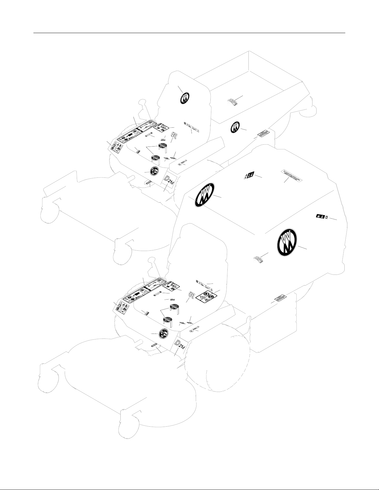
TRACTOR DECALS
Walker Product Decals
1 8600-33 RH Fender Body, RH Side Near Seat 1 1
2 5800 Walker Mower (4" Round) Utility Bed (one on each side) 0 2
3 5856-1 Made in USA Body 1 1
4 5800-11 Walker (8" Round) 10.0 Bushel Catcher (one on each side) 2 0
5 8821-9 Decal, D21d Body 1 1
Danger Decals Warning Decals Caution Decals
6 8600-34 Warning, Read Manual Body 1 1
7 5810-3 Decal, Hydro Warning Bridge Assembly and LH Gear Axle Drive Assembly 2 2
8 8600-10 Danger, Pinch Point 10.0 Bushel Catcher Mounting Frame Assembly 2 0
(one on each side)
9 8600-4 Danger, Rotating Blower Blades Body, Near Body Chute 1 0
Maintenance Decals
10 8600-30 Parking Brake Body, RH Side Below Seat 1 1
11 8600-23 Danger, Body Latch Body, RH Side Below Seat 1 1
12 NS Caution (19426-87903 Kubota) Air Cleaner Cover 1 1
13 NS Caution (19426-87881 Kubota) Radiator 1 1
14 8600-16 Front Body Closure Rear Cross Member, Body 1 1
15 7827 Oil Level Jackshaft Support 1 1
16 5810-1 Axle Oil Level Gear Axle Drive Assemblies (one on each) 2 2
17 8600-31 Throttle Body, LH Side 1 1
18 6875 PTO Alignment Arrow Universal Joint Tube Assembly 1 1
19 NS Sealed Reservoir Hydrostatic Drives (one on each) 2 2
20 5869 Removable Screen 10.0 Bushel Catcher Removable Screen 1 0
NOTE: All parts requiring decals are shipped with decals applied.
Effective Date 10-04-13
2
Page 5
Beginning S/N 124860
Use only genuine Walker® replacement parts.
TRACTOR DECALS
.
.
2
.
12
.
SD Model
1
.
6
1. 2.
.
16
19
.
3
.
Refer to Decks
Parts Manual
for Deck Decals
8600-23
.
18
.
.
8600-16
11
.
.
7
10
15
7
.
5
14
.
16
.
17
.
4
.
2
13
.
.
8
20
8
GHS Model
1
6
1. 2.
16
19
3
Refer to Decks
Parts Manual
for Deck Decals
12
8600-16
8600-23
11
10
7
15
14
.
9
8600-4
13
4
16
7
18
5
17
Effective Date 10-04-13
3
Page 6

ITEM PART DESCRIPTION NO.
NO. NO. REQ’D
ITEM PART DESCRIPTION NO.
NO. NO. REQ’D
Beginning S/N 124860
Use only genuine Walker® replacement parts.
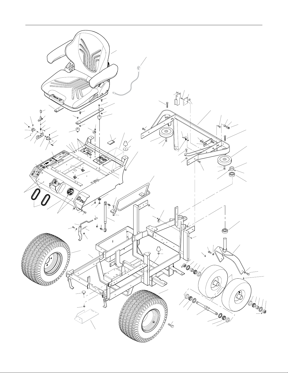
BODY / CHASSIS ASSEMBL Y (GHS MODELS)
Seat Assembly
1 6103-14 Suspension Seat 1
2 6103-35 Suspension Seat Mount 2
3 7440-7 Shock Mount 4
4 6105-1 Shoulder Washer 2
Rear Bumper Assembly (GHS Models Only)*
5 NS Recovery T ank Mount 1
(19449-72502 Kubota)
6 7047-5 Mount Plate 1
7 7516-7 7.0 / 10.0 Rear Bumper 1
8 7516-5 Catcher Pivot Bushing 2
9 5162 Roller Wheel (5" Rubber) 2
10 7517-2 Catcher Pivot Plate 2
11 5832 Cable Clamp (1/2) 2
Body Assembly
12 7833-2 Cable Clamp (1 x 1/4) 1
13 5977-3 Grommet (9/16) 1
14 6105-3 Harness Clip 2
15 NS Body ID Plate 1
16 5845 Rubber Bumper (1.50 OD x 1.25) 4
17 7422 Panel Guard 1
18 5989-4 Dome Plug (3/8) 4
19 5989-3 Dome Plug (5/16) 2
20 7146 13mm Ball Stud 2
21 7145 Gas Spring Assembly 1
(Includes Item # 20)
22 7844 Rubber Bumper (1.25 OD x .250) 1
23 7854 Plastic Tip, Red 1
24 7222 Extension Spring (1/4 x 3) 1
25 7383-3 Body Latch Hook (2-1/2 Side Bars) 1
26 5989-9 Dome Plug (1/4) 8
27 7100-7 Front Body 1
28 5180 Edge Molding, Lever Opening 2
29 5989-55 Dome Plug (1/2) 1
30 5989-5 Dome Plug (7/16) 1
Tilt-Up Latch Assembly***
31 5847 Plastic Tip 1
32 5744-20 Spring Arm, Tilt-Up Latch 1
33 5744-10 Spring Pivot Bushing 1
34 5744-15 Compression Spring (3/8 x 5/8) 1
35 5744-13 Mount Angle, LH 1
36 5744-12 Hook, Tilt-Up Latch 1
37 5744-14 Mount Angle, RH 1
Chassis Assembly
38 5267-1 Retainer Collar (1") (Includes Item # F413) 1
39 5270-1 Pivot Bearing 2
40 7420 Tail Wheel Fork 1
41 5830-3 Grease Fitting (45 Degree) 2
42 8039 Nut, T ail Wheel Axle 2
43 8037-1 Seal, Outer (1-3/4 x 1-1/8) 2
44 8038-1 Spacer, T ail Wheel Axle 2
(.750 ID x 1.125 OD)
45 8037 Bearing Cone (3/4 ID) 4
46 8037-2 Bearing Race 4
47 8035 Tail Wheel & T ire (13 x 5.00-6) 2
(With Bearing Race)
7035-1 Tail Wheel T ire (13 x 5.00-6) **
8036 Tail Wheel & Hub (6 x 3.25) **
(Includes Items # 40 & 46)
7420-20 Dual T ail Wheel & Tire Assembly **
(Includes Items # 42-45 & 47-49)
48 8768-2 Seal, Reverse Lip 2
49 8038 Tail Wheel Axle (3/4 x 10-3/8) 1
50 7070 Wheel & Tire (18 x 9.50-8) 2
7070-1 Drive Tire (18 x 9.50-8) **
5070-4 Wide Wheel (8 x 7) **
51 7300-6 Chassis Frame (2-1/2 Side Bars) 1
Fasteners
F002 10-24 Keps Nut 3
F004 1/4-20 Keps Nut 6
F005 1/4-20 ESNA Nut 1
F009 5/16-18 Whiz Locknut 15
F012 3/8-16 Keps Nut 8
F013 3/8-16 Whiz Locknut 2
F014 3/8-16 ESNA Nut 4
F020 5/16-18 ESNA Nut 1
F025 10-24 x 3/8 PPHMS 1
F026 10-24 x 1/2 PPHMS 2
F029 1/4-20 x 1/2 Hex Bolt 2
F031 1/4-20 x 5/8 Hex Bolt 1
F034 5/16-18 x 3/4 Hex Bolt 6
F038 3/8-16 x 1 Hex Bolt 6
F040 3/8-16 x 1-1/2 Hex Bolt 2
F042 3/8-16 x 2-1/4 Hex Bolt 2
F050 1/4 SAE Washer 1
F051 3/8 SAE Washer 2
F059 3/8 Wave Spring W asher 2
F093 5/16-18 x 1 Hex Bolt 1
F104 1/4-20 x 3/4 PFH Bolt 4
F151 3/8-16 x 7/8 Hex Bolt 2
F157 1/2-20 x 1-1/4 Wheel Lug Bolt 8
F191 3/8 x 1-1/2 x 3/16 Washer 2
F205 5/16-18 x 1/4 Set Screw, Knurl Point 2
F206 #2 x 3/16 Drive Pin 2
F218 7/16 Split Lock Washer 2
F219 7/16-14 x 1-1/4 Hex Bolt 2
F241 .375 x .875 x .10 Washer 4
F341 Coil Roll Pin (7/64 x 9/16) 1
F342 5/16 Conical Washer 2
F413 5/16-24 x 5/16 Set Screw 2
F429 5/16-18 x 1/2 SFH Screw 4
* Rear Bumper Assembly for SD Models is not shown here.
Refer to BODY ASSEMBLY (SD MODELS), Page 8.
** Service Part Only
*** Complete Tilt-Up Latch Assembly Kit available by ordering
kit # 5747.
4
Effective Date 10-04-13
Page 7
Beginning S/N 124860
Use only genuine Walker® replacement parts.
BODY / CHASSIS ASSEMBL Y (GHS MODELS)
.
.
F020
.
37
F004
.
26
.
F029
F342
1
Refer to
Electrical Assembly
.
.
F104
.
5
.
11
F012
.
F205
F026
F002
.
6
F012
.
42
.
F004
.
F013
10
.
43
F026
.
41
.
44
F241
F038
.
.
45
.
F219
46
.
.
7
F059
F014
F413
.
F218
.
F151
.
.
8
F241
.
F012
F042
.
9
.
38
.
.
F413
39
39
.
40
.
47
F218
F219
.
F034
.
.
F429
2
.
31
.
32
.
33
.
.
34
.
36
F342
.
29
F341
18
F004
.
30
1. 2.
F029
..
35
.
F093
F429
3
.
.
18
19
18
.
14
F034
.
F025
F009
.
12
.
26
8600-23
.
13
14
.
F009
.
15
8600-4
2
.
3
.
F206
Refer to
GHS Group
.
16
.
F191
18
F009
.
F038
9
.
F042
.
F059
.
F104
.
F014
F038
17
19
.
.
F002
.
F031
F014
.
.
F050
25
.
F051
.
F040
F009
.
23
.
24
.
28
27
26
.
F009
20
.
4
F034
.
.
20
F009
.
F002
F012
11
21
F005
50
51
16
F009
41
.
22
F009
Effective Date 10-04-13
Refer to
Electrical
Assembly
50
.
F157
46
45
F205
44
43
42
.
.
46
45
48
49
48
45
46
5
Page 8

ITEM PART DESCRIPTION NO.
NO. NO. REQ’D
ITEM PART DESCRIPTION NO.
NO. NO. REQ’D
Beginning S/N 124860
Use only genuine Walker® replacement parts.
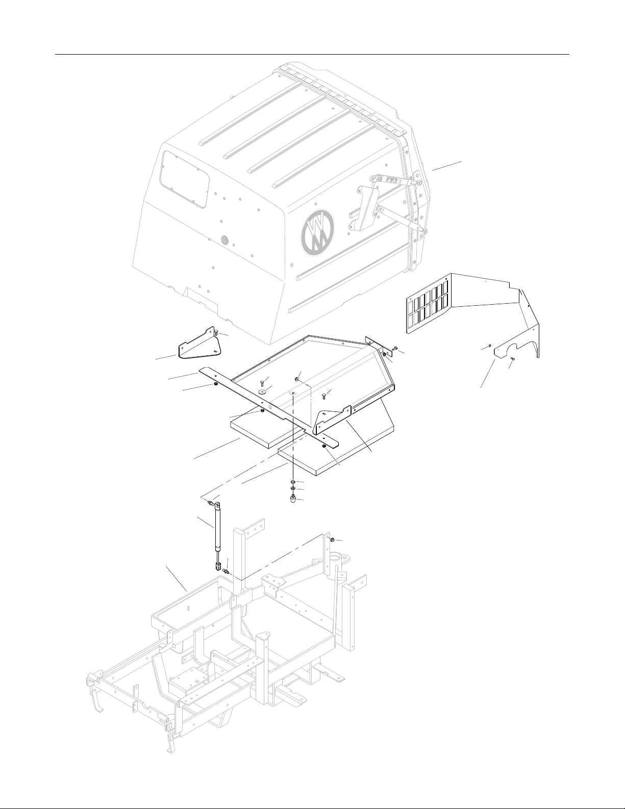
REAR BODY ASSEMBL Y (GHS MODELS)
Rear Body Assembly (GHS Models)
1 8515-13 Catcher Handle Plate, LH 1
2 8515-14 Catcher Handle Plate, RH 1
3 8615-2 Catcher Support Frame, 10.0 1
4 7190-2 Insulation Foam Pad, RH 1
5 7190-1 Insulation Foam Pad, LH 1
6 7146 13mm Ball Stud 2
7 7145 Gas Spring Assembly 1
(Includes Item # 6)
8 5845 Rubber Bumper (1.50 x 1.25) 1
9 7105-5 Rear Body Panel 1
Fasteners
F002 10-24 Keps Nut 6
F004 1/4-20 Keps Nut 5
F009 5/16-18 Whiz Locknut 4
F025 10-24 x 3/8 PPHMS 6
F031 1/4-20 x 5/8 Hex Bolt 2
F032 1/4-20 x 3/4 Hex Bolt 1
F178 1/4 x 1 Fender Washer 1
F390 1/4-20 x 7/8 Carriage Bolt 2
NOTE: Rear Bumper Assembly for GHS Models is not shown here.
Refer to BODY / CHASSIS ASSEMBLY (GHS MODELS),
Page 4.
6
Effective Date 10-04-13
Page 9
Beginning S/N 124860
Use only genuine Walker® replacement parts.
REAR BODY ASSEMBL Y (GHS MODELS)
Refer to
GHS 10.0 Bushel
Catcher Assembly
.
.
.
F390
2
.
3
.
F032
F004
.
.
F178
.
F009
F390
.
.
F031
.
F004
.
.
F002
.
F025
9
Refer to
Body / Chassis Assembly
(GHS Models)
F004
4
1
F004
.
5
.
6
F009
.
F009
8
7
F009
6
Effective Date 10-04-13
7
Page 10

ITEM PART DESCRIPTION NO.
NO. NO. REQ’D
ITEM PART DESCRIPTION NO.
NO. NO. REQ’D
Beginning S/N 124860
Use only genuine Walker® replacement parts.
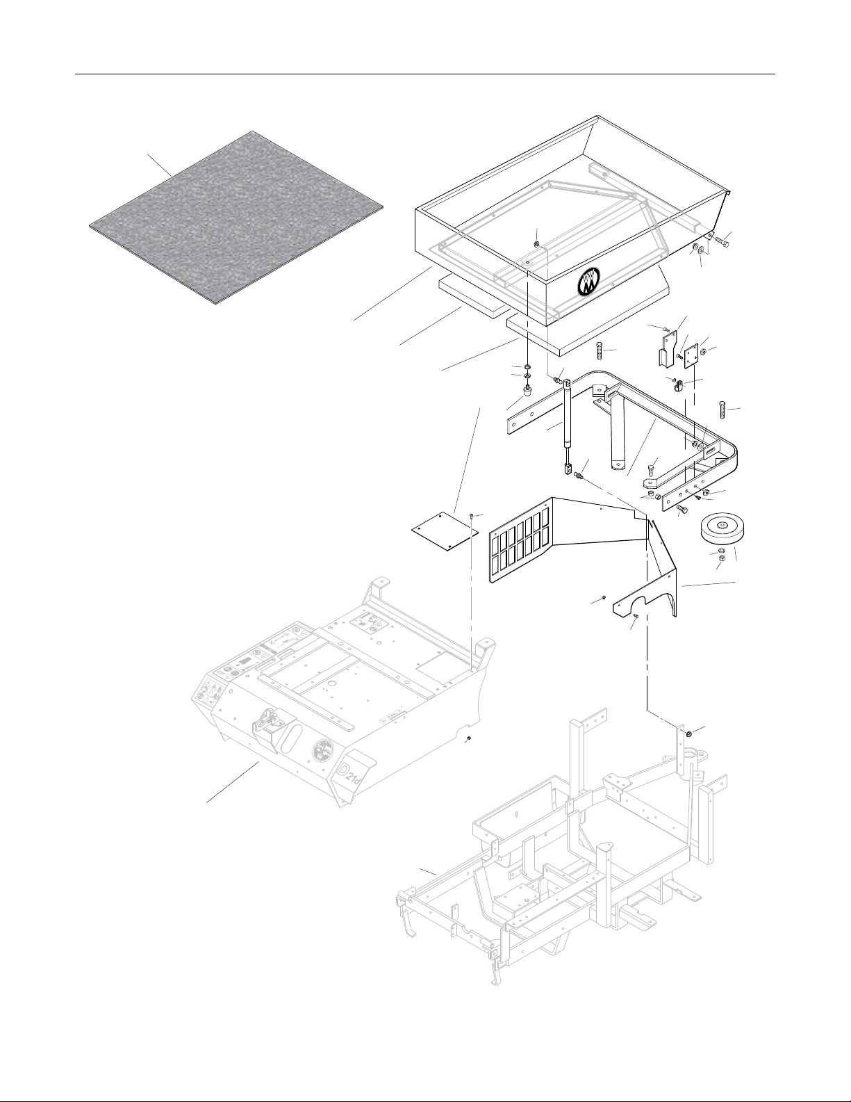
BODY ASSEMBL Y (SD MODELS)
Utility Bed Assembly
1 8650-10 Bed Liner (21.5 x 27.5) 1
2 7650-3 Utility Bed (Includes Item # 1) 1
3 7190-2 Insulation Foam Pad, RH 1
4 7190-1 Insulation Foam Pad, LH 1
Rear Bumper Assembly (SD Models)
5 7153-3 Cover Plate 1
6 5845 Rubber Bumper (1.50 x 1.25) 1
7 7146 13mm Ball Stud 2
8 7145 Gas Spring Assembly 1
(Includes Item # 7)
9 7521-5 Rear Bumper 1
10 NS Recovery Tank Mount 1
(19449-72502 Kubota)
11 7047-5 Mount Plate 1
12 5832 Cable Clamp (1/2) 1
13 5162 Roller Wheel (5" Rubber) 2
14 7105-5 Rear Body Panel 1
Fasteners
F002 10-24 Keps Nut 11
F004 1/4-20 Keps Nut 4
F009 5/16-18 Whiz Locknut 4
F012 3/8-16 Keps Nut 6
F013 3/8-16 Whiz Locknut 4
F014 3/8-16 ESNA Nut 2
F025 10-24 x 3/8 PPHMS 6
F026 10-24 x 1/2 PPHMS 1
F038 3/8-16 x 1 Hex Bolt 6
F040 3/8-16 x 1-1/2 Hex Bolt 2
F042 3/8-16 x 2-1/4 Hex Bolt 2
F051 3/8 SAE Washer 4
F059 3/8 Wave Spring W asher 2
F104 1/4-20 x 3/4 PFH Bolt 4
F128 10-24 x 3/8 PTHMS 4
NOTE: Refer to BODY / CHASSIS ASSEMBLY (GHS MODELS),
Page 4 for all common parts used on both models.
8
Effective Date 10-04-13
Page 11
Beginning S/N 124860
Use only genuine Walker® replacement parts.
BODY ASSEMBL Y (SD MODELS)
.
.
1
.
F009
.
.
.
F002
.
F038
F013
F013
F038
.
2
3
4
F009
F009
.
.
5
6
.
7
.
F104
.
F042
.
8
7
9
.
F012
.
F128
.
.
F051
.
10
.
F104
.
F059
.
11
.
12
F051
F014
.
F004
.
F026
.
.
F040
F004
.
13
F042
14
Refer to
Body / Chassis Assembly
(GHS Models)
8600-23
F002
.
F025
1. 2.
F009
F002
Refer to
Body / Chassis Assembly
(GHS Models)
Effective Date 10-04-13
9
Page 12

ITEM PART DESCRIPTION NO.
NO. NO. REQ’D
ITEM PART DESCRIPTION NO.
NO. NO. REQ’D
Beginning S/N 124860
Use only genuine Walker® replacement parts.
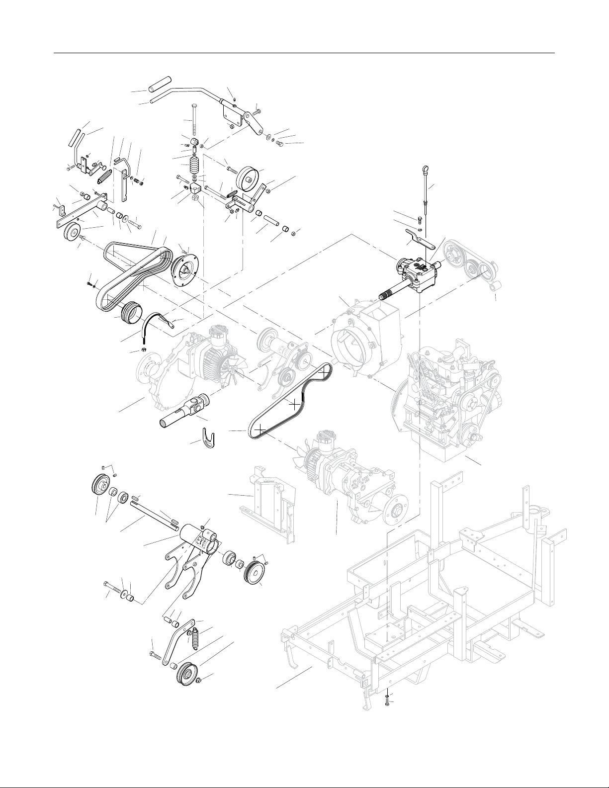
MAIN COMPONENT POWER TRANSMISSION (GHS MODELS)
Clutch Lever Assembly
1 5830 Grease Fitting 4
2 5229 Extension Spring (1/2 x 2-1/4) 1
3 7243 Clutch Idler Pulley 1
4 7368-5 PTO Belt Tightener (1.75 TAB) 1
5 7201-3 Fiberglide Bearing 6
6 7201-6 Inner Race (3-5/8) 1
7 7303-9 Clutch Actuator Block 1
8 5830-3 Grease Fitting (45 Degree) 2
9 7226 Compression Spring (3/4 x 2-1/2) 1
10 7380 Knuckle Joint 1
11 7303-7 Clutch Actuator Rod 1
12 7378 Pivot Bearing (7/16 x 9/16) 1
13 7358 Clutch Lever 1
(Includes Items # 1 & 14)
14 4850 Handle Grip 1
PTO Drive Shaft Assembly
15 7050-1 Dipstick, Gearbox 1
16 7377-1 Brake Band Guide 1
17 7050-11 PTO Gearbox / Flange Pulley 1
18 7248 Ground Drive Belt, Micro-V 1
19 7275-9 Quick Coupler Installation T ool **
20 7275-16 Universal Joint Tube Assembly / Spline 1
21 7303-2 Brake Band (13-5/8) 1
22 7236-1 PTO Drive Pulley (4-1/2/3V) 1
(Includes Items # F168 & F226)
23 7237-30 Engine Pulley (Flywheel Mount) 1
(Includes Item # F221)
24 7230 Engine PTO Belt 1
25 6238 Drive Belt (3VX345) 1
Jackshaft Assembly
26 7240-4 Jackshaft Drive Pulley (3.3/3V) 1
(Includes Items # F067 & F171)
27 5268 Bearing with Collar (3/4) 2
28 7273 Jackshaft (3/4 x 8-7/8) 1
29 7393-7 Hydro Jackshaft Mount 1
7394-1 Hydro Jackshaft Mount Assembly *
(Includes Items # 1, 5, 27-29 & 31)
30 5841 Retainer Washer (3/8 x 1-1/4) 2
31 7201-4 Inner Race (1-1/2) 2
32 7349-50 Idler Arm 1
33 7349-2 Extension Spring (3/4 x 4) 1
34 6325-3 Spacer Bushing (9/16) 1
35 5245 Idler Pulley (3") 1
36 7241-2 Transmission Drive Pulley (3-1/4MV) 1
(Includes Items # F067 & F171)
Ground Drive Release Assembly
37 7245-1 Idler Pulley (3/8 Groove) 1
38 7374 Ground Drive Release Arm 1
39 7390 Idler Arm Guide 1
40 7406-1 Handle Grip, Red 1
41 7376 Handle, Ground Drive Release 1
(Includes Item # 40)
42 5221 Extension Spring (3/4 x 4) 1
43 7854 Plastic Tip, Red 1
44 7375 Spring Arm, Ground Drive Idler Release 1
(Includes Item # 43)
45 7225 Compression Spring (7/16 x 1/2) 1
Fasteners
F002 10-24 Keps Nut 1
F004 1/4-20 Keps Nut 2
F005 1/4-20 ESNA Nut 2
F009 5/16-18 Whiz Locknut 3
F012 3/8-16 Keps Nut 3
F013 3/8-16 Whiz Locknut 2
F029 1/4-20 x 1/2 Hex Bolt 1
F041 3/8-16 x 1-3/4 Hex Bolt 1
F042 3/8-16 x 2-1/4 Hex Bolt 2
F047 3/8-16 x 4-1/2 Hex Bolt 1
F050 1/4 SAE Washer 1
F060 AN960516 Washer 2
F061 1/4 Internal Star Lock Washer 1
F067 3/16 x 3/16 x 1 Key 2
F069 3/32 x 1/2 Cotter Pin 1
F108 3/8-16 x 2 Hex Bolt 1
F116 1/4-20 x 1-1/4 Hex Bolt 1
F167 5/16-18 Hex Nut 1
F168 5/16 Split Lock Washer 9
F171 5/16-18 x 3/8 Set Screw 4
F178 1/4 x 1 Fender Washer 1
F187 1/4-20 x 1-1/2 Hex Bolt 2
F221 M8 x 1.25 x 16 PFH Bolt 5
F226 5/16-18 x 7/8 Hex Bolt 9
F245 3/8-24 x 7/8 SFH Cap Screw 1
F252 10-24 x 3/4 PFHMS 1
F255 5/16-18 x 1-1/2 Hex Bolt 2
F275 5/16-18 x 2 Hex Bolt 1
F288 5/16-18 ESNA Jam Nut 1
* Service Part Only
** The Quick Coupler Installation Tool is used to assist the instal-
lation of the Quick Coupler Tube and PTO Shaft connection by
holding the disconnect ring in the retracted position when
joined to the tractor spline shaft on the PTO gearbox.
10
Effective Date 10-04-13
Page 13
MAIN COMPONENT POWER TRANSMISSION (GHS MODELS)
.
.
F252
.
.
14
13
.
40
.
.
41
.
42
.
43
44
.
.
F187
F012
.
39
F004
1
.
F116
.
5
.
.
F002
.
.
38
37
.
45
.
F005
F050
.
.
F042
31
5
30
.
11
.
10
.
8
10
.
F060
9
.
F275
8
7
.
.
25
24
.
.
F221
23
F245
F226
F168
.
.
22
.
21
.
F069
F005
.
1
.
F255
.
F009
.
12
.
F041
.
.
F060
.
.
F047
.
F288
2
.
F009
.
.
1
5
F167
6
.
F178
.
F061
.
F029
.
3
.
.
F012
4
.
F226
.
F012
5
F168
.
16
.
15
.
17
Refer to
GHS Group
Refer to
GHS Group
.
Refer to
Hydrostatic Ground
Drive Assemblies
.
F171
.
.
.
26
27
28
30
5
F042
29
.
F067
.
F067
F108
.
.
19
Refer to
Hydrostatic Ground
Drive Assemblies
.
31
5
.
32
.
F013
20
1
.
F013
18
Refer to
Engine Group
Refer to
F171
.
27
27
Hydrostatic Ground
Drive Assemblies
36
.
33
.
34
35
Beginning S/N 124860
Effective Date 10-04-13
Use only genuine Walker® replacement parts.
Refer to
Body / Chassis Assembly
(GHS Models)
F168
F226
11
Page 14

ITEM PART DESCRIPTION NO.
NO. NO. REQ’D
ITEM PART DESCRIPTION NO.
NO. NO. REQ’D
Beginning S/N 124860
Use only genuine Walker® replacement parts.
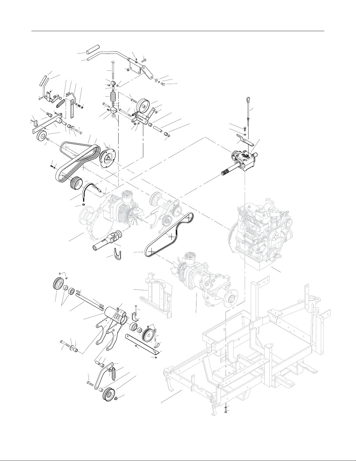
MAIN COMPONENT POWER TRANSMISSION (SD MODELS)
Clutch Lever Assembly
1 5830 Grease Fitting 4
2 5229 Extension Spring (1/2 x 2-1/4) 1
3 7243 Clutch Idler Pulley 1
4 7368-5 PTO Belt Tightener (1.75 TAB) 1
5 7201-3 Fiberglide Bearing 6
6 7201-6 Inner Race (3-5/8) 1
7 7303-9 Clutch Actuator Block 1
8 5830-3 Grease Fitting (45 Degree) 2
9 7226 Compression Spring (3/4 x 2-1/2) 1
10 7380 Knuckle Joint 1
11 7303-7 Clutch Actuator Rod 1
12 7378 Pivot Bearing (7/16 x 9/16) 1
13 7358 Clutch Lever 1
(Includes Items # 1 & 14)
14 4850 Handle Grip 1
PTO Drive Shaft Assembly
15 7050-1 Dipstick, Gearbox 1
16 7377-1 Brake Band Guide 1
17 7050-11 PTO Gearbox / Flange Pulley 1
18 7248 Ground Drive Belt, Micro-V 1
19 7275-9 Quick Coupler Installation T ool **
20 7275-16 Universal Joint Tube Assembly / Spline 1
21 7303-2 Brake Band (13-5/8) 1
22 7236-1 PTO Drive Pulley (4-1/2/3V) 1
(Includes Items # F168 & F226)
23 7237-30 Engine Pulley (Flywheel Mount) 1
(Includes Item # F221)
24 7230 Engine PTO Belt 1
25 6238 Drive Belt (3VX345) 1
Jackshaft Assembly
26 7240-4 Jackshaft Drive Pulley (3.3/3V) 1
(Includes Items # F067 & F171)
27 5268 Bearing with Collar (3/4) 2
28 7273 Jackshaft (3/4 x 8-7/8) 1
29 7393-7 Hydro Jackshaft Mount 1
7394-1 Hydro Jackshaft Mount Assembly *
(Includes Items # 1, 5, 27-29 & 31)
30 5841 Retainer Washer (3/8 x 1-1/4) 2
31 7201-4 Inner Race (1-1/2) 2
32 7349-50 Idler Arm 1
33 5221-1 Extension Spring (3/4 x 5) 1
34 6325-3 Spacer Bushing (9/16) 1
35 5245 Idler Pulley (3") 1
36 7394-6 Idler Pulley Spring Mount 1
37 7833 Cable Clamp (7/8 x 1/4) 1
38 7241-2 Transmission Drive Pulley (3-1/4MV) 1
(Includes Items # F067 & F171)
39 8539 Starter Relay Mount 1
Ground Drive Release Assembly
40 7245-1 Idler Pulley (3/8 Groove) 1
41 7374 Ground Drive Release Arm 1
42 7390 Idler Arm Guide 1
43 7406-1 Handle Grip, Red 1
44 7376 Handle, Ground Drive Release 1
(Includes Item # 43)
45 5221 Extension Spring (3/4 x 4) 1
46 7854 Plastic Tip, Red 1
47 7375 Spring Arm, Ground Drive Idler Release 1
(Includes Item # 46)
48 7225 Compression Spring (7/16 x 1/2) 1
Fasteners
F002 10-24 Keps Nut 1
F004 1/4-20 Keps Nut 4
F005 1/4-20 ESNA Nut 2
F009 5/16-18 Whiz Locknut 3
F012 3/8-16 Keps Nut 3
F013 3/8-16 Whiz Locknut 2
F029 1/4-20 x 1/2 Hex Bolt 1
F041 3/8-16 x 1-3/4 Hex Bolt 1
F042 3/8-16 x 2-1/4 Hex Bolt 2
F047 3/8-16 x 4-1/2 Hex Bolt 1
F050 1/4 SAE Washer 1
F060 AN960516 Washer 2
F061 1/4 Internal Star Lock Washer 1
F067 3/16 x 3/16 x 1 Key 2
F069 3/32 x 1/2 Cotter Pin 1
F090 1/4-20 x 2-1/2 Hex Bolt 2
F108 3/8-16 x 2 Hex Bolt 1
F116 1/4-20 x 1-1/4 Hex Bolt 1
F167 5/16-18 Hex Nut 1
F168 5/16 Split Lock Washer 9
F171 5/16-18 x 3/8 Set Screw 4
F178 1/4 x 1 Fender Washer 1
F187 1/4-20 x 1-1/2 Hex Bolt 2
F221 M8 x 1.25 x 16 PFH Bolt 5
F226 5/16-18 x 7/8 Hex Bolt 9
F245 3/8-24 x 7/8 SFH Cap Screw 1
F252 10-24 x 3/4 PFHMS 1
F255 5/16-18 x 1-1/2 Hex Bolt 2
F275 5/16-18 x 2 Hex Bolt 1
F288 5/16-18 ESNA Jam Nut 1
* Service Part Only
** The Quick Coupler Installation Tool is used to assist the instal-
lation of the Quick Coupler Tube and PTO Shaft connection by
holding the disconnect ring in the retracted position when
joined to the tractor spline shaft on the PTO gearbox.
12
Effective Date 10-04-13
Page 15
MAIN COMPONENT POWER TRANSMISSION (SD MODELS)
.
.
F252
.
.
14
.
13
43
.
.
44
.
45
.
46
47
.
.
F116
F004
1
.
.
F187
.
F012
.
42
5
.
.
41
F002
.
40
.
48
.
F005
.
F050
.
.
F042
31
5
30
.
11
.
10
8
10
.
9
.
.
F275
8
7
.
.
25
24
.
.
F221
23
F245
F226
F168
.
.
22
.
F069
.
.
1
F255
.
F009
.
12
.
.
F060
F041
.
F060
.
.
.
F047
F288
2
.
F167
F009
1
.
3
F012
.
4
F012
.
F178
F061
.
5
.
.
F029
.
.
15
6
5
.
F226
.
F168
.
.
17
16
21
F005
.
Refer to
Hydrostatic Ground
Drive Assemblies
.
F171
.
.
.
26
27
28
30
.
5
F042
.
29
.
F067
.
F067
F108
.
.
19
Refer to
Hydrostatic Ground
Drive Assemblies
31
5
.
32
.
F013
20
18
Refer to
Engine Group
1
.
F090
.
39
F171
.
27
27
F004
F090
.
37
38
.
36
Refer to
Hydrostatic Ground
Drive Assemblies
F004
.
33
.
.
34
35
F013
Refer to
Body / Chassis Assembly
(GHS Models)
F168
F226
Beginning S/N 124860
Effective Date 10-04-13
Use only genuine Walker® replacement parts.
13
Page 16

ENGINE GROUP
ITEM PART DESCRIPTION NO.
NO. NO. REQ’D
Engine Assembly
1 7929-1 Actuating Solenoid 1
2 7305-3 Inline Ball Joint 1
3 7343-1 Solenoid Mount 1
4 7305-1 Solenoid Linkage Rod 1
5 NS Kubota Diesel Engine 1
(D 722 Kubota)
6 7341 Throttle Cable Mount Bracket 1
7 5975-3 Cable Tie (50# x 7") 2
Fuel Tank Assembly
8 5832 Cable Clamp (1/2) 1
9 5083-8 T ank Tube (13") 1
10 5879-3 Hose Clamp (1/2) 2
11 M11 1 Fuel Line (1/4 x 16-1/2) **
12 7833 Cable Clamp (7/8 x 1/4) 2
13 M113 Fuel Line (3/16 x 32) **
14 5879-2 Hose Clamp, Silver (7/16) 2
15 7840-2 Hose Clamp (1/4 to 5/8) 6
16 M247 Fuel Line (5/16 x 14-1/2) **
17 NS Fuel Filter (19204-43010 Kubota) 1
18 M247 Fuel Line (5/16 x 25-1/2) **
19 7021 Fuel Filter (15231-43560 Kubota) 1
20 7389 Splash Guard 1
21 7048 Trash Guard 1
22 M247 Fuel Line (5/16 x 17-1/2) **
23 NS Fuel Pump (12691-52031 Kubota) 1
24 7020 Fuel Filter (In-Line) 1
25 5086-7 Hose (1/4 x 6) 1
26 5020-2 Fuel Filter, In Tank 1
27 8046-3 Fuel T ank, 4.7 Gallon, Diesel 1
28 7082-1 Fuel T ank Cap, Diesel *
29 5083-1 Bushing, Rubber *
30 7046-1 Fuel Return Tube 1
ITEM PART DESCRIPTION NO.
NO. NO. REQ’D
Fasteners
F002 10-24 Keps Nut 1
F003 1/4-28 Hex Nut 1
F004 1/4-20 Keps Nut 9
F009 5/16-18 Whiz Locknut 4
F025 10-24 x 3/8 PPHMS 1
F027 10-24 x 5/8 PPHMS 1
F029 1/4-20 x 1/2 Hex Bolt 6
F031 1/4-20 x 5/8 Hex Bolt 5
F032 1/4-20 x 3/4 Hex Bolt 1
F050 1/4 SAE Washer 1
F052 5/16 Ext. Star Lock Washer 2
F061 1/4 Internal Star Lock Washer 4
F069 3/32 x 1/2 Cotter Pin 1
F079 A/A66D Aluminum Pop Rivet 2
F091 5/16-18 x 5/8 Hex Bolt 2
F182 1/4 x 5/8 x 1/8 Washer 2
F235 5/16-18 x 2-1/2 Hex Bolt 1
F324 M8 x 1.25 x 12 Hex Bolt 2
* Service Part Only
** Required hose specications:
M111 - 1/4" ID fuel/oil/vapor hose (Gates 4219-0103 or
equivalent)
M113 - 3/16" ID fuel/oil/vapor hose (Gates 4219-0093 or
equivalent)
M247 - 5/16" ID low permeation (<15g/m^2/day) fuel hose
(Parker 38905 or equivalent)
NOTE: Refer to ELECTRICAL CONNECT ORS, Page 40 for identi-
cation of all Electrical Wiring Service Parts.
NOTE: Decals for this assembly are not shown here. Refer to
TRACTOR DECALS, Page 2 for Decal listing and placement information.
14
Beginning S/N 124860
Effective Date 10-04-13
Use only genuine Walker® replacement parts.
Page 17

Beginning S/N 124860
Use only genuine Walker® replacement parts.
.
ENGINE GROUP
Refer to Air Intake
And Exhaust Group
.
F029
.
F061
.
.
.
F091
7
.
.
F235
F004
F091
.
F182
F004
.
.
F003
.
F069
F050
.
.
.
.
4
.
2
F324
F052
.
16
15
F009
6
.
15
.
17
F009
.
.
19
17
.
F004
.
F031
.
1
.
10
.
9
.
14
30
.
11
.
13
.
14
7
.
F079
.
12
F079
12
28
.
27
.
29
.
10
24
15
15
F004
.
23
15
22
.
F025
.
8
.
F009
15
20
.
5
.
3
.
18
.
.
F027
F029
Refer to Air Intake
And Exhaust Group
Refer to
Electrical Assembly
25
.
.
21
F004
26
Refer to
Body / Chassis Assembly
(GHS Models)
Effective Date 10-04-13
F029
F004
F031
F031
F061
F032
.
.
F002
15
Page 18

Beginning S/N 124860
Use only genuine Walker® replacement parts.
ITEM PART DESCRIPTION NO.
NO. NO. REQ’D
ITEM PART DESCRIPTION NO.
NO. NO. REQ’D
AIR INT AKE AND EXHAUST GROUP
Precleaner Assembly
1 7026-2 Remote Precleaner (Includes Item # 2) 1
2 7840-5 Hose Clamp (1-1/2 to 2) 4
3 7028-5 Precleaner Tube, 1-3/4 / GHS 1
4 7440 Shock Mount (1.0 OD x 3/4) 3
5 7028-20 Rear Precleaner Mount 1
6 7032 Elbow, Precleaner 1
7 5088-8 Air Cleaner Assembly *
(Includes Items # 9-13, 16 & 17)
8 5088-1 Air Cleaner Band 1
9 5090-3 Safety Filter Insert 1
10 5090-1 Air Cleaner Cartridge 1
11 5088-5 Air Cleaner Draw Latch 2
12 5088-11 Air Cleaner Cap 1
13 5090-2 Vacuator V alve 1
14 7016 Air Intake Hose 1
15 7840 Hose Clamp (1-1/4 to 1-3/4) 1
16 5091-9 Street Elbow 90° (1/8 x 1/8) 1
17 5091-0 1/8 Pipe Thread Male W/Barb 1
18 M258 V acuum Hose (7") 1
19 5091-13 Air Flow Indicator W/Bracket 1
(Vacuum 20" H2O)
20 7031-2 Tube Support Arm 1
Exhaust Assembly
Fasteners
F002 10-24 Keps Nut 2
F009 5/16-18 Whiz Locknut 11*
F012 3/8-16 Keps Nut 3**
F025 10-24 x 3/8 PPHMS 2
F038 3/8-16 x 1 Hex Bolt 3**
F091 5/16-18 x 5/8 Hex Bolt 2
F217 7/16-14 Hex Nut 4
F218 7/16 Split Lock Washer 4
F219 7/16-14 x 1-1/4 Hex Bolt 4
(GHS Models use only 3)
F226 5/16-18 x 7/8 Hex Bolt 1
F239 7/16-14 x 1-1/2 Hex Bolt 1***
F249 M10 Split Lock Washer 8
F253 M8 x 1.25 x 35 Bolt, GR 8 3
F255 5/16-18 x 1-1/2 Hex Bolt 2*
F311 M10 x 1.25 x 20 Hex Bolt 8
F327 M8 x 1.25 x 45 GR 8 Hex Bolt 1
F482 8-32 Nylock Nut 2
Δ
F483 8-32 x 3/4 PPHMS 2
* Two (2) F009 and two (2) F255 fasteners are reused from
Clutch Lever Assembly. Refer to MAIN COMPONENT
POWER TRANSMISSION (GHS OR SD MODELS), Pages
10 or 12.
21 7437-1 Exhaust Manifold Shield 1
22 NS Spring Washer (04512-50080 Kubota) 4
23 7437-6 Engine Brace 1
(Includes Items # 20, F002 & F025)
24 NS Mufer (15262-12110 Kubota) 1
25 NS Mufer Gasket (15371-12370 Kubota) 2
26 7034 Spacer, Mufer 1
27 7354 Motor Mount 2
28 7306-15 Water T emperature Sender 1
29 7306-12 T emperature Sender Adapter 1
30 7306-13 Oil Pressure Switch 1
31 7023 Oil Filter (15841-32439 Kubota) 1
32 7047-2 Manifold Heat Shield 1
33 7013-2 T ail Pipe 1
** One (1) F012 and one (1) F038 fastener are reused from Rear
Bumper Assembly. Refer to BODY / CHASSIS ASSEMBLY
(GHS MODELS), Page 4.
*** GHS Models Only
Δ
Required hose specications:
M258 - 7/64" ID automotive vacuum hose
NOTE: Decals for this assembly are not shown here. Refer to
TRACTOR DECALS, Page 2 for Decal listing and place-
ment information.
16
Effective Date 10-04-13
Page 19

AIR INT AKE AND EXHAUST GROUP
.
.
.
20
F009
.
2
.
3
F009
.
1
F009
4
.
.
F483
F255
.
F009
.
.
5
F038
.
4
F009
.
.
2
.
.
F482
19
18
17
16
.
14
.
.
F012
.
F012
6
2
.
2
7
.
F091
.
8
F009
25
15
.
F249
.
F311
.
F219
.
27
7
.
.
10
9
.
25
.
26
.
.
12
.
11
.
13
.
.
F025
.
.
21
22
.
F002
.
24
.
F253
22
F327
.
F009
23
.
F226
F012
.
.
.
28
.
29
.
30
.
31
33
32
F038
.
F218
.
F217
Refer to
Body / Chassis Assembly
(GHS Models)
.
Refer to
Engine Group
F239
(GHS Models Only)
Beginning S/N 124860
Effective Date 10-04-13
Use only genuine Walker® replacement parts.
17
Page 20

Beginning S/N 124860
Use only genuine Walker® replacement parts.
ITEM PART DESCRIPTION NO.
NO. NO. REQ’D
ITEM PART DESCRIPTION NO.
NO. NO. REQ’D
RADIA TOR GROUP
Radiator Assembly
1 7840-4 Hose Clamp (3/4 to 1-1/2) 1
2 7017-3 Upper Radiator Hose 1
3 7840-3 Hose Clamp (1/2 to 1-1/4) 3
4 7427-21 Fan Mount Tab, LH 2
5 7429-6 Radiator Cooling Fan 1
6 7427-5 Radiator Fan Shroud 1
7 NS Recovery Tank Hose Clamp 2
(15501-72470 Kubota)
8 M110 Recovery T ank Hose 1**
9 NS Coolant Recovery Tank and Hose 1
(19059-72090 Kubota)
10 5975-3 Cable Tie (50# x 7") 2
11 7427-9 Radiator Cap *
12 7427 Radiator 1
13 7431-1 Radiator Channel Seal (1/4 x 1/2 x 13.5) 2
14 7435 Radiator Brace 1
15 7432 Shock Mount (1.00 OD x .75) 1
16 7425-3 Radiator Screen 1
17 7426 Screen Channel 2
18 7429-7 Fan Blade Replacement *
(Includes Items # F089, F143,
F222, F237 & F254)
19 7430 Radiator Guard 1
20 5841 Retainer Washer (3/8 x 1-1/4) 2
21 7434 Washer (3/8 x 1-1/4 x 1/4) 4
22 7427-7 Debris Shield, Shroud 1
23 7427-22 Fan Mount T ab, RH 2
24 7017-2 Lower Radiator Hose 1
Fasteners
F004 1/4-20 Keps Nut 6
F014 3/8-16 ESNA Nut 2
F029 1/4-20 x 1/2 Hex Bolt 5
F031 1/4-20 x 5/8 Hex Bolt 7
F061 1/4 Internal Star Lock Washer 7
F073 1/4 x 1.5 Fender Washer 2
F089 Belleville Washer , SS *
F090 1/4-20 x 2-1/2 Hex Bolt 2
F129 10-24 x 1/2 PTHMS 4
F143 10-32 x 1/4 Whiz Lock Bolt *
F222 Thrust Washer *
F237 Spring Ring *
F254 Fender Washer *
* Service Part Only
** Required hose specications:
M110 - 7/32" ID EDM Hose
NOTE: Decals for this assembly are not shown here. Refer to
TRACTOR DECALS, Page 2 for Decal listing and place-
ment information.
18
Effective Date 10-04-13
Page 21

Beginning S/N 124860
Use only genuine Walker® replacement parts.
RADIA TOR GROUP
.
Refer to
Engine Group
.
1
.
3
F129
.
2
.
.
F129
.
3
.
.
4
5
23
.
F031
.
F061
.
6
Refer to
Body / Chassis Assembly
(GHS Models)
.
8
.
7
.
.
11
.
12
9
7
.
9
.
10
Refer to
Body / Chassis Assembly
.
16
(GHS Models)
.
17
13
.
24
3
.
22
13
.
14
15
F004
F029
F061
.
.
F061
F029
F004
F061
F029
17
Refer to
Body / Chassis Assembly
(GHS Models)
F004
F090
F014
.
.
F073
F029
18
F004
F004
.
F090
F061
.
19
21
F031
F004
.
.
21
.
20
F031
Effective Date 10-04-13
19
Page 22

Beginning S/N 124860
Use only genuine Walker® replacement parts.
ITEM PART DESCRIPTION NO.
NO. NO. REQ’D
ITEM PART DESCRIPTION NO.
NO. NO. REQ’D
HYDROST A TIC GROUND DRIVE ASSEMBLIES
Transmission Lockout Assembly
1 5028-3 Transmission Lockout Assembly *
(Includes Items # 2-5, F023, F027 & F081)
2 5847 Plastic Tip 2
3 5057 Lockout Cam 2
(Includes Item # F081)
4 5028-5 Lockout Lever 2
5 5027-5 Lockout Mount 1**
Ground Drive Assemblies
6 6209-3 Bridge Assembly 1
7 5832 Cable Clamp (1/2) 1
8 7394-7 Throttle Cable Mount Bracket 1
9 6243-1 Hydro Fan, CW 1
10 5025 Hydrostatic Drive, CCW (700-052) 1
11 6206-1 Air Vent V alve *
12 6200-9 Gear Axle Drive Assembly 2
(Includes Items # 11 & 13)
13 6207-12 Pipe Plug (1/4 NPTF) 4
14 5126 Cable Retainer 1
(Uses existing bolt on
Gear Axle Drive Assembly)
15 6233-1 Pinion Gear 2
16 6234 Spacer, Pinion Gear 2
17 6201 O-Ring Seal 2
18 7244 Hydro Pulley (3-7/8/MV) 2
(Includes Items # F064 & F359)
19 6243-2 Hydro Fan, CCW 1
20 5026 Hydrostatic Drive, CW (700-051) 1
Deck Support Arm Assemblies
21 6430-10 Outboard Mount, LH 1
22 6431-1 Deck Support Arm, LH 1
(Includes Item # 26)
23 5775-2 Hitch Pin (# 6) 2
24 6431-2 Deck Support Arm, RH 1
(Includes Item # 26)
25 6430-9 Outboard Mount, RH 1
26 5830 Grease Fitting 2
27 6840-1 Support Arm Bushing (2-1/16) 2
Transmission Repair Parts
28 5025-5 Input Shaft *
29 5025-8 Bearing, Input Shaft *
30 5025-7 Snap Ring *
31 5025-2 Seal, Input Shaft *
32 5022 Reservoir to Casting Gasket *
33 5024 Reservoir Cap and Gasket *
34 5023 Transmission Reservoir Kit *
35 5023-1 Rubber Bladder *
36 5025-6 O-Ring & Plug Assembly *
37 5025-3 Seal, Control Shaft *
Fasteners
F012 3/8-16 Keps Nut 2
F023 10-24 ESNA Nut 2
F026 10-24 x 1/2 PPHMS 1
F027 10-24 x 5/8 PPHMS 2
F036 1/4-20 x 1/2 SBH Screw 2
F038 3/8-16 x 1 Hex Bolt 4
F040 3/8-16 x 1-1/2 Hex Bolt 4
F043 3/8-16 x 3 Hex Bolt 7
F053 7/16 Internal Star Lock Washer 4
F063 3/8 Internal Star Lock Washer 16
F064 1/8 x 1/2 Woodruff Key (#3) 4
F081 A/A45D Aluminum Pop Rivet 2
F160 External Snap Ring (.669 Shaft) 2
F178 1/4 x 1 Fender Washer 2
F194 7/16 x 1-1/4 x 1/8 Washer 2
F200 7/16-20 x 3 Grade 8 Bolt 2
F244 7/16-20 x 3/4 Hex Bolt 2
F262 3/8-16 x 4 Hex Bolt All Thread 2
F359 5/16-18 x 5/16 Set Screw 4
(Unbrako Knurl Point)
* Service Part Only
** Part not used on Jackshaft side of tractor .
20
Effective Date 10-04-13
Page 23

HYDROST A TIC GROUND DRIVE ASSEMBLIES
.
.
.
.
32
.
31
.
30
.
29
28
.
33
.
34
.
35
.
.
36
F038
.
F063
.
1
.
25
.
23
F200
F053
30
.
F012
F026
.
7
.
20
.
F012
.
8
F063
.
37
.
11
.
12
.
13
F063
.
F359
.
.
.
F160
.
F244
15
.
F053
.
.
13
F064
.
.
16
17
18
F036
F178
19
.
26
.
.
27
F064
F359
18
.
F359
.
F359
F064
6
Refer to
Main Component Power
Transmission (GHS Models)
.
F262
F262
.
9
.
F178
.
F036
.
F043
F063
.
.
F023
5
.
.
.
F081
.
.
F027
2
3
4
.
10
11
12
.
14
13
.
F040
F064
F194
F194
27
17
26
.
.
16
F160
F063
15
24
23
22
Beginning S/N 124860
Effective Date 10-04-13
Use only genuine Walker® replacement parts.
F053
F244
F053
F063
F043
13
F200
21
21
Page 24

ITEM PART DESCRIPTION NO.
NO. NO. REQ’D
ITEM PART DESCRIPTION NO.
NO. NO. REQ’D
Beginning S/N 124860
Use only genuine Walker® replacement parts.
STEERING CONTROL ASSEMBLIES
Transmission Spring Assemblies
1 6201-2 Shock Mount Gear Drive, RH 1
2 5146 10mm Ball Stud 4
3 6199-3 Steering Lever Dampener Assembly 2
4 6201-1 Shock Mount Gear Drive, LH 1
5 5214-2 Ball Joint (5/16-24) Nylon Lined 2
6 6212-1 Transmission Control Arm, LH 1
7 5213-3 Control Rod (6") 1
8 5665-1 Compression Spring (2-1/2) 2
9 5463-2 Steering Lever Actuator 2
10 7201-2 Fiberglide Bearing 1/2" 2
11 5213-4 Control Rod (14-3/4") 1
12 5212 Transmission Control Arm, RH 1
Steering Lever & FSC Assemblies
13 5173 FSC Actuator Rod 1
14 5172 Bearing, Delrin (.255 ID x .379 OD x .250) 1
15 5142-2 FSC Actuator Cam 1
16 5830 Grease Fitting 6
17 5141 FSC Friction Washer (1-1/2 x 3/8 x 1/16) 2
18 5140-15 FSC Friction Body 1
(Includes Item # 16)
19 5142-7 FSC Key W/Stop 1
5140-13 FSC Control Assembly *
(Includes Items # 15-19, F192 & F193)
20 5850-2 Handle Grip, Foam (5-1/2) 2
21 5223 Extension Spring (1/4 x 5-1/2) 2
22 5450 D-Clip 2
23 5391-3 Steering Lever Support 1
24 5217 Pivot Pin, Steering Lever 1
25 5451-10 Steering Lever Assembly , LH / Adjustable 1
(Includes Items # 9, 10, 16, F360 & F489)
5451-7 Steering Lever Arm, LH / Adjustable *
26 5453-10 Steering Lever Handle, Adjustable 2
(Includes Items # 20 & F345)
27 5219 Extension Spring (3/4 x 6-3/4) 1
28 5280 Clevis (1/4") 1
29 5281-5 Clevis Pin (1/4 x 0.80) 1
30 5470-1 Speed Control Stop 1
31 5450-10 Steering Lever Assembly , RH / Adjustable 1
(Includes Items # 9, 10, 16, F360 & F489)
5450-7 Steering Lever Arm, RH / Adjustable *
32 5862 FSC Knob 1
33 7170 FSC Lever Assembly 1
(Includes Item # 16)
34 5975-3 Cable Tie (50# x 7") 1
Fasteners
F003 1/4-28 Hex Nut 1
F004 1/4-20 Keps Nut 6
F007 5/16-18 Jam Nut 1
F008 5/16-24 Keps Nut 2
F009 5/16-18 Whiz Locknut 5
F010 5/16-24 ESNA Nut 2
F024 5/16-24 Jam Nut 2
F029 1/4-20 x 1/2 Hex Bolt 2
F032 1/4-20 x 3/4 Hex Bolt 4
F034 5/16-18 x 3/4 Hex Bolt 1
F050 1/4 SAE Washer 3
F051 3/8 SAE Washer 2
F064 1/8 x 1/2 Woodruff Key (#3) 2
F068 1/8 x 1 Cotter Pin 1
F069 3/32 x 1/2 Cotter Pin 1
F093 5/16-18 x 1 Hex Bolt 1
F183 .312 x .700 x .074 Washer 2
F186 5/64 x 1/2 Cotter Pin 1
F188 1/4-20 Self-Locking Nut 4
F192 3/8-24 Self-Locking Nut 1
F193 3/8 Belleville Spring Washer 3
F198 .250 x .625 x .040 Washer , SS 2
F353 3/8-16 ESNA LP Nut 2
F345 1/4-20 x .770 Knurled Bolt 4
F360 1/4-20 x 3/8 Hex Bolt 2
F401 .504 x .751 x .030 Washer 1
F489 Washer 1/4 x 7/8 x .090 2
* Service Part Only
22
Effective Date 10-04-13
Page 25

Beginning S/N 124860
Use only genuine Walker® replacement parts.
.
.
F009
STEERING CONTROL ASSEMBLIES
.
1
.
2
.
Refer to
Hydrostatic Ground
Drive Assemblies
3
.
.
.
F345
.
F360
F489
26
.
F401
32
33
Refer to
Electrical Assembly
.
F032
16
F032
.
20
.
F198
.
31
F009
.
F188
.
21
.
22
16
2
16
.
.
.
10
F010
.
9
30
.
8
.
.
F093
.
34
.
F007
.
F183
.
24
29
F004
.
F029
F004
.
11
.
.
.
.
F186
F003
F050
.
.
F034
.
13
F032
.
14
28
.
27
F188
F198
.
26
.
25
23
.
F068
F004
.
F024
.
15
.
F050
F008
F009
.
.
.
16
.
F069
.
.
5
.
F064
.
F051
.
12
F353
.
17
F004
.
18
.
17
19
.
F193
.
F024
F064
.
6
F051
F353
F192
20
F345
.
7
21
22
F009
16
F183
8
2
Refer to
Hydrostatic Ground
Drive Assemblies
5
F008
.
2
3
4
F009
9
Effective Date 10-04-13
F010
10
F489
F360
23
Page 26

ITEM PART DESCRIPTION NO.
NO. NO. REQ’D
ITEM PART DESCRIPTION NO.
NO. NO. REQ’D
Beginning S/N 124860
Use only genuine Walker® replacement parts.
THROTTLE CONTROL ASSEMBL Y
Throttle Control Assembly
1 5833 Cable Clamp (1/4) 2
2 7220 Throttle Cable 1
3 NS 10-32 Jam Nut 2
4 5150 Ball Joint (10-32) 2
5 5108-7 Control Lock T ab 1
6 5108-10 Friction Washer (.125) 1
7 5108-1 Control Lever, Throttle 1
8 5108-5 Throttle Control Knob, Red 1
9 5108-11 Friction Washer (.062) 1
10 5108-8 Control Bracket 1
11 7108 Control Assembly *
(Includes Items # 5-7, 9, 10 & F201)
12 7112 Throttle Control and Cable Assembly *
(Complete Control and Cable Assembly)
(Includes Items # 2, 4, 8, 11 & F232)
Fasteners
F002 10-24 Keps Nut 4
F005 1/4-20 ESNA Nut 1
F025 10-24 x 3/8 PPHMS 4
F201 1/4 Belleville Spring Washer 2
F232 10-32 Keps Nut 2
* Service Part Only
NOTE: Decals for this assembly are not shown here. Refer to
TRACTOR DECALS, Page 2 for Decal listing and place-
ment information.
24
Effective Date 10-04-13
Page 27

Beginning S/N 124860
Use only genuine Walker® replacement parts.
.
THROTTLE CONTROL ASSEMBL Y
Refer to
8600-23
Body / Chassis Assembly
(GHS Models)
8600-4
Refer to
1. 2.
.
Engine Group
F002
.
.
F232
. .
.
.
10
9
.
8
.
.
7
.
6
5
.
F005
.
3
4
F201
F002
F232
2
.
F002
4
3
2
.
F025
.
11
F025
1
F025
F002
.
1
Effective Date 10-04-13
12
25
Page 28

Beginning S/N 124860
Use only genuine Walker® replacement parts.
ITEM PART DESCRIPTION NO.
NO. NO. REQ’D
ITEM PART DESCRIPTION NO.
NO. NO. REQ’D
P ARKING BRAKE ASSEMBL Y
Parking Brake Assembly
1 7406-1 Handle Grip, Red 1
2 7406-8 Parking Brake Lever (4-1/4) 1
3 7406-2 Lever Mount 1
4 5830 Grease Fitting 1
5 7407 Clevis Pin (3/16 x 1/2) 2
6 7404-6 Brake Actuator Arm 2
7 7405 Pin, Transmission Lock 2
8 7402 Clevis 2
9 7408 Compression Spring (1/2 x 3/4) 2
10 7415 Rubber Dust Shield (5/8 x 3/8 x 1/32) 2
11 5567-3 O-Ring Seal (1/4 x 3/8) 4
12 7403 Plunger Bushing, Gear Axle 2
13 7404-7 Brake Actuator Mount 2
14 7412 Clevis Pin (3/16 x 5/8) 2
15 5833 Cable Clamp (1/4) 2
16 7410 Brake Control Cable, LH (25.5") 1
17 7409 Brake Control Cable, RH (20.5") 1
18 7401-3 Cable Mount Bracket 1
19 7401-1 Cable Pull Rod 1
20 5552 Ball Joint (1/4-28) 1
Fasteners
F002 10-24 Keps Nut 2
F003 1/4-28 Hex Nut 1
F004 1/4-20 Keps Nut 4
F025 10-24 x 3/8 PPHMS 2
F029 1/4-20 x 1/2 Hex Bolt 3
F032 1/4-20 x 3/4 Hex Bolt 1
F054 AN960616 Washer 2
F072 1/4 “E” Retainer Ring 2
F086 #10 SAE Washer 4
F109 1/8 x 5/8 Roll Pin 2
F11 1 1/8 x 3/4 Cotter Pin 1
F112 5/8 x 1-1/4 x .03 Washer 2
F127 1/16 x 1/2 Cotter Pin 4
F261 AN960616L W asher 5
F287 1/4-28 Keps Nut 1
26
Effective Date 10-04-13
Page 29

Beginning S/N 124860
Use only genuine Walker® replacement parts.
.
P ARKING BRAKE ASSEMBL Y
.
1
8600-23
N
1. 2.
Refer to
Body / Chassis Assembly
(GHS Models)
17
8600-18
1. 2.
8600-4
.
.
F029
.
18
F004
20
19
.
.
.
F003
.
F287
.
F111
.
.
.
.
2
F032
F004
3
.
.
4
F029
.
F261
16
Refer to
Hydrostatic
Ground Drive
Assemblies
.
F025
.
F086
.
5
.
F072
.
.
F127
8
F261
.
.
.
F002
F054
.
.
F112
14
15
F002
16
F025
F086
F127
.
F109
F072
.
6
.
7
.
9
.
10
.
11
.
12
.
13
F086
5
F086
6
7
F109
F127
8
9
F261
15
F054
10
11
F112
14
12
F127
13
Effective Date 10-04-13
27
Page 30

Beginning S/N 124860
Use only genuine Walker® replacement parts.
ITEM PART DESCRIPTION NO.
NO. NO. REQ’D
ITEM PART DESCRIPTION NO.
NO. NO. REQ’D
GHS GROUP
Delivery Chute Assembly
1 5515-2 Elbow Delivery Spout 1
2 5592-13 Backing Plate, Grass-Pak® Switch 1
3 5578 Rear Clip, Chute Mount 1
4 5577 Side Clip, Chute Mount 2
5 8511-1 Delivery Chute W/Clips / 10.0 1
(Includes Items # 3, 4, 6, F362 & F411)
6 5578-10 Front Clip, Chute Mount 1
7 7530-4 Body Chute (10.5 Blower) 1
Blower Belt Tightener Assembly
8 7238-6 Blower Drive Pulley 1
(Includes Items # F075, F114 & F231)
9 7234-2 Blower Belt (Micro-V) 1
10 7239-1 Blower Pulley (Micro-V) 1
(Includes Items # F067, F075 & F114)
11 7364-2 Torsion Spring 1
12 7201-3 Fiberglide Bearing 2
13 5830-3 Grease Fitting (45 Deg.) 1
14 7364-1 Blower Belt Tightener Arm 1
15 7201-4 Inner Race (1-1/2) 1
16 5841 Retainer Washer (3/8 x 1-1/4) 1
17 5245 Idler Pulley (3") 1
Blower Assembly
18 8539 Starter Relay Mount 1
19 5268 Bearing W/Collar (3/4) 2
20 7544 Blower Assembly (10.5") 1
(Includes Items # 19, 21-25, F004, F009,
F029, F050, F131, F168 & F426)
21 7543-3 Blower Housing (10.5) 1
22 7545-2 Blower Output Shaft (10.5) 1
23 7545 Blower Wheel (10.5") 1
24 7543-1 Blower Faceplate (10.5) 1
25 7526 Intake Tube (10.5 Blower) 1
26 7528-2 Skid Bar (10.5" Blower) 1
27 5595-2 Intake Cover/GHS **
28 7833 Cable Clamp (7/8 x 1/4) 1
Fasteners
F002 10-24 Keps Nut 6
F004 1/4-20 Keps Nut 3
F009 5/16-18 Whiz Locknut 7
F012 3/8-16 Keps Nut 3
F026 10-24 x 1/2 PPHMS 2
F029 1/4-20 x 1/2 Hex Bolt 3
F034 5/16-18 x 3/4 Hex Bolt 1
F039 3/8-16 x 1-1/4 Hex Bolt 1
F040 3/8-16 x 1-1/2 Hex Bolt 1
F042 3/8-16 x 2-1/4 Hex Bolt 1
F050 1/4 SAE Washer 1
F054 AN960616 Washer 1
F067 3/16 x 3/16 x 1 Key 1
F075 5/16-18 x 1/2 SQH Set Screw 2
F079 A/A66D Aluminum Pop Rivet 6
F090 1/4-20 x 2-1/2 Hex Bolt 1
F114 5/16-18 x 5/8 SQH Set Screw 2
F128 10-24 x 3/8 PTHMS 4
F131 5/16-18 x 1/2 Hex Bolt 3
F132 1/4-20 x 2-3/4 Hex Bolt 1
F168 5/16 Split Lock Washer 3
F217 7/16-14 Hex Nut 1
F218 7/16 Split Lock Washer 1
F231 1/4 x 3/4 Woodruff Key (# 806) 1
F281 7/16-14 x 1-3/4 Hex Bolt 1
F362 A/A62D Alum. Pop Rivet (3/16D x 13/32L) 2
F411 3/16 Bulbex Rivet 6
F426 1/4-20 x 1/2 Carriage Bolt 1
* Service Part Only
** Plugs Blower when GHS is not in use. Furnished only with
Mulching Decks, SD Decks used on a GHS Tractor, Rotary
Broom Attachment and Snowblower Attachment. Use of this
part may be replaced by installing Blower Lockout Kit (P/N
7541).
NOTE: Refer to ELECTRICAL CONNECT ORS, Page 40 for identi-
cation of all Electrical Wiring Service Parts.
28
Effective Date 10-04-13
Page 31

Beginning S/N 124860
Use only genuine Walker® replacement parts.
GHS GROUP
Refer to
Electrical Connectors
.
F029
.
1
.
F026
.
2
Refer to
Electrical Assemblies
(GHS 10.0 Bushel Components)
.
F079
3
12
F002
.
9
.
F075
.
8
.
F231
F114
.
F114
F075
.
.
F067
10
.
.
.
.
15
F012
11
12
13
14
.
.
F362
6
.
.
4
F411
.
5
.
.
F411
F411
.
.
4
F128
7
.
.
F002
F132
.
F426
.
20
Refer to Main
Component Power
Transmission
(GHS Models)
.
F090
.
18
.
F040
.
F012
.
.
F054
17
.
.
F042
.
.
16
19
Refer to
.
.
.
21
F004
.
.
F050
F004
.
F131
F168
19
22
23
.
F009
.
28
.
.
Body / Chassis Assembly
(GHS Models)
25
.
27
Effective Date 10-04-13
24
.
.
.
F217
F218
.
F039
26
F009
F012
.
F034
.
F281
29
Page 32

GHS POWERFIL® ASSEMBL Y (10.0)
ITEM PART DESCRIPTION NO.
NO. NO. REQ’D
10.0 GHS Powerl® Assembly
1 5551-3 BearingCap,Powerl® 1
2 5551-1 Pivot Bearing (#S3PP) 2
3 5518-2 Pivot,DeliverySpout 1
4 5517-2 PivotMount 1
5 5552 BallJoint(1/4-28) 2
6 5558-1 Powerl
7 5553-3 Bushing,Powerl
®
PushRod 1
®
Actuator 4
8 5553-1 CompressionSpring(1/2x2) 2
9 5558-2 Powerl
®
ActuatorRod 1
5549 ActuatorRodAssembly *
(IncludesItems#5-9&F003)
10 5519-3 MotorMountNut(5/8-24) *
11 5554 ActuatorArm 1
12 5519-2 MotorMountWasher *
13 5976-2 Grommet(3/16x3/4) 1
14 5519-5 ActuatorMotor(12V) 1
(IncludesItems#11&12)
ITEM PART DESCRIPTION NO.
NO. NO. REQ’D
Fasteners
F002 10-24KepsNut 10
F003 1/4-28HexNut 3
F026 10-24x1/2PPHMS 1
F037 10-24x5/8PTHScrew 2
F054 AN960616Washer 1
F085 3/16RivetBackupWasher 1
F101 10-24x1-1/4SHCScrew 1
F109 1/8x5/8RollPin 1
F129 10-24x1/2PTHMS 6
F261 AN960616LWasher 1
F287 1/4-28KepsNut 1
* ServicePartOnly
30
Beginning S/N 124860
Effective Date 10-04-13
Use only genuine Walker® replacement parts.
Page 33

GHS POWERFIL® ASSEMBL Y (10.0)
.
F026
.
F085
.
F002
.
14
.
.
11
.
F101
F003
.
12
.
.
F002
10
13
Refer to
Electrical Assemblies
(GHS 10.0 Bushel Components)
F129
.
5
F003
.
.
7
.
8
7
9
7
.
8
7
F002
F003
.
6
.
.
1
.
.
F261
2
5
2
.
F054
.
F109
Refer to
3
Electrical Assemblies
(GHS 10.0 Bushel
Components)
4
F002
.
F287
F037
.
F129
.
F037
F129
F002
Beginning S/N 124860
Effective Date 10-04-13
Use only genuine Walker® replacement parts.
Refer to
GHS Group
31
Page 34

ITEM PART DESCRIPTION NO.
NO. NO. REQ’D
ITEM PART DESCRIPTION NO.
NO. NO. REQ’D
Beginning S/N 124860
Use only genuine Walker® replacement parts.
GHS 10.0 BUSHEL CA TCHER ASSEMBLY
Upper Bafe Screen Assembly (Removable)
1 7512-2 Removable Screen (3/16 Hole) 1**
(Includes Items # 2, 5, F025 & F190)
2 7506 Knob / Threaded Insert (10-24) 2
3 8606-3 Channel T op, LH 1
4 8606-2 Channel Bottom 2
5 7856-1 Edge Molding (26") 1
6 7507 Screen Seal (27-1/2) 1
7 7505 Mustache Spring 2
8 8606 C-Channel (10.0) 1
8606-20 C-Channel With Spring (10.0) *
(Includes Items # 7, 8 & F340)
9 8606-4 Channel T op, RH 1
10.0 Exhaust Deector Door Assembly
10 8607-6 Upper Seal Support 1
11 8607-5 Upper Door Seal 1
12 8607-11 Backup Plate 1
13 8512-3 10.0 Catcher Box Door 1
(Includes Items # 10-14, 16, 17,
F085, F330 & F411)
14 5583 Handle 1
15 8607-1 Door Mount, LH 1
16 8607-12 Upper Door Stiffener 1
17 8607-7 Lower Door Stiffener 1
18 8607-8 Door Guide 1
19 8607-2 Door Mount, RH 1
GHS 10.0 Bushel Catcher Assembly
20 8608-5 Center Strap 1
21 8608-3 Upper Frame Doubler 2
22 8608-1 Outside Box Strap, LH 2
23 8608-2 Lower Frame Doubler 2
24 8608-4 Center Frame Doubler 1
25 8608-11 Catcher Door Finger 1
26 8608-6 Catcher Mount 1
27 8610-4 Catcher Dump Flap W/Plate 10.0 1
28 8610-3 Backing Plate, Dump Flap 1
29 7584 Reinforcing Strap 1
30 5103-5 Pivot Bushing Inner 2
31 5801-3 Decal Plate, Round (Set of 2) 1
32 7620-3 Pivot Bushing (1/2 x 9/16) 2
33 8608-7 Hinge Plate, LH 1
34 5103-7 Outside Torsion Bushing 2
35 8607-4 Upper Arm 2
36 5214-12 Ball Joint (5/16-24) 4
37 5155-12 5/16 Ball Stud 2
38 5155-4 Gas Spring 2
39 5147 Spring Clip 4
40 8155-1 Gas Spring Cover, LH 1
41 8607-3 Lower Arm 2
42 5103-6 Pivot Bushing Outer 2
43 5155-13 3/4 Ball Stud 2
44 5523-6 Gas Spring Plate 2
45 8608-10 Box Support, Gas Spring 2
46 7532-1 Handle, Catcher Lift 2
47 5977 Grommet (1/2 x 7/8 x 1/16) 2
48 8117 Wire Harness Channel 1
49 8602-3 10.0CatcherW/OPowerl®, Gray
8602-4 10.0CatcherW/Powerl
(Includes Door)
®
, Gray *
*
(Includes Door)
8610-5 10.0 Bushel Catcher Box, Gray *
50 8607-9 Powerl® Cover Plate 1
51 8155-2 Gas Spring Cover, RH 1
52 8608-8 Hinge Plate, RH 1
53 8608-9 T orsion Bar 1
5598-2 Optional Dump Bag (Not Shown)
May be ordered as an option. Contact your Walker dealer .
Fasteners
F002 10-24 Keps Nut 29
F004 1/4-20 Keps Nut 25
F009 5/16-18 Whiz Locknut 4
F020 5/16-18 ESNA Nut 2
F024 5/16-24 Jam Nut 4
F025 10-24 x 3/8 PPHMS 4
F026 10-24 x 1/2 PPHMS 2
F027 10-24 x 5/8 PPHMS 8
F029 1/4-20 x 1/2 Hex Bolt 10
F049 5/16 SAE Washer 8
F050 1/4 SAE Washer 2
F068 1/8 x 1 Cotter Pin 2
F079 A/A66D Aluminum Pop Rivet 14
F085 3/16 Rivet Backup Washer 13
F094 8-32 x 1/2 PTHMS 6
F129 10-24 x 1/2 PTHMS 17
F190 #10 Internal Star Lock Washer 2
F195 1/4-20 x 3/4 PPHMS, SS 4
F196 1/4-20 x 1 PPHMS, SS 4
F208 5/16-18 x 2-1/4 Hex Bolt 2
F230 1/4-20 x 1-1/4 PPHMS, SS 4
F242 1/4-20 x 7/8 PPHMS, SS 8
F330 3/16D x 21/32L Rivet, SS 9
F340 Rivet, Aluminum 4
F351 Aluminum Pop Rivet 6
F360 1/4-20 x 3/8 Hex Bolt 2
F390 1/4-20 x 7/8 Carriage Bolt 4
F411 3/16 Bulbex Rivet 10
F456 5/16-18 x 3/4 SBH Cap Screw, SS 4
F503 1/4-20 x 1-1/2 PPHMS, SS 1
F524 3/16 x 3/8 Aluminum Rivet, Black 6
* Service Part Only
** This screen can be replaced by P/N 7512-3 Removable
Screen(3/4"holes)forimprovedairowperformanceinwet
conditions.
32
Effective Date 10-04-13
Page 35

Beginning S/N 124860
Use only genuine Walker® replacement parts.
GHS 10.0 BUSHEL CA TCHER ASSEMBLY
.
51
F026
..
39
F027
38
F208
F049
.
.
.
F094
50
46
Refer to
Rear Body Assembly
(GHS Models)
F085
F027
F351
44
F002
F002
42
43
F390
F129
F129
F009
F129
F129
F129
F002
.
F025
37
F456
F027
45
.
F390
49
F049
F049
F002
F129
41
F129
.
.
7
35
F024
F024
.
47
.
F340
F456
36
.
34
F129
F002
F002
F002
.
8
36
F351
.
F009
F002
48
F002
F002
.
.
F068
.
F002
47
F129
F340
F340
52
32
F002
.
30
F020
F004
F004
Refer to
Rear Body Assembly
(GHS Models)
F004
.
4
.
F049
F004
.
.
.
9
F002
.
53
.
29
F340
7
.
F020
46
F079
.
1
F025
.
F190
.
.
2
3
4
F002
F002
5
6
F025
F129
F129
.
12
.
.
.
F085
.
F330
.
10
.
11
19
.
22
.
F195
F068
F242
F242
.
.
21
.
.
.
F004
F029
F004
F004
...
F196
23
.
F004
F230
.
F004
.
F029
.
F085
.
F079
F079
.
F360
F050
20
F029
F085
21
.
F503
.
25
23
.
F230
24
F196
26
.
F360
.
F050
.
18
16
.
F411
22
.
13
F330
.
14
.
15
F029
17
F049
.
30
31
28
F004
27
F004
F004
.
.
F524
F390
F002
F351
F009
32
F002
45
F002
.
F129
33
.
44
.
34
.
35
F129
.
.
F351
.
.
F129
.
F027
43
F049
42
41
F024
36
F456
.
F024
F009
F049
.
.
36
F456
F002
F085
.
40
.
F026
F027
.
F049
.
.
.
37
38
39
F002
F208
F027
Effective Date 10-04-13
33
Page 36

Beginning S/N 124860
Use only genuine Walker® replacement parts.
ITEM PART DESCRIPTION NO.
NO. NO. REQ’D
ITEM PART DESCRIPTION NO.
NO. NO. REQ’D
INSTRUMENT PANEL ASSEMBL Y
Instrument Panel Assembly
1 7307-2 Instrument Panel Cover (Optional) **
7396-1 Instrument Panel Assembly 1
(Includes Items # 2-4, 6-16, 25-27,
F228, F250 & F251)
2 7307-7 Panel Frame 1
3 7307-8 Panel Faceplate W/Decal 1
4 7386 Panel Gasket 1
5 7960-6 Ignition Key (1 Set) *
6 7960-5 Ignition Switch (with Keys) 1
(Includes Item # 6)
7 8996-9 Red Indicator Light Assembly 2
8 7941-3 Boot, Circuit Breaker 2
9 7941-5 Circuit Breaker (7 Amp) 1
10 7941-2 Circuit Breaker (10 Amp) 1
11 8990-1 Hourmeter (Global) 1
12 5995 Toggle Switch (Off-On) 1
13 5995-2 Switch Boot 1
14 7306-14 Water T emperature Gauge 1
15 8997 Voltmeter Gauge 1
16 7947-3 Wire Harness, Instrument Panel 1
17 5975-1 Cable Tie (18# x 3-3/4") 2
18 7307-1 Shock Mount (1.0 x .25) 3
19 7391 Panel Box Mount Plate 2
20 8385 Panel Box W/Graphic 1
21 7977-1 Grommet (1/8 x 1-1/16) 1
22 7307-16 Lining, Panel Box (1/8) 1
23 6941-6 Relay Switch (30/40 Amp) *
24 6941-7 Relay Mount *
25 8536 Warning Horn 1
26 6942 Relay Switch (30/40 Amp) NC 3
(Includes Items # 23 & 24)
27 7947-8 Jumper Wire 1
Fasteners
F002 10-24 Keps Nut 1
F004 1/4-20 Keps Nut 6
F025 10-24 x 3/8 PPHMS 1
F228 #6 x 5/8 PPHSMS, SS 8
F238 J Clip, Instrument Panel C15520-6A 8
F250 6-32 x 1/2 PPHMS 1
F251 6-32 Keps Nut 2
F448 6-32 x 5/16 PPHMS 1
* Service Part Only.
** May be ordered as an option. Contact your Walker dealer .
NOTE: Refer to ELECTRICAL CONNECT ORS, Page 40 for identi-
cation of all Electrical Wiring Service Parts.
34
Effective Date 10-04-13
Page 37

Beginning S/N 124860
Use only genuine Walker® replacement parts.
ORG/
WHT
YEL/
RED
26
.
F025
DETAIL B
RED
RED
RED
To Wiring
Harness
PUR
YEL/RED
BLU
BLK
.
F002
DETAIL A
BLU
.
F448
.
26
.
GRA
B
25
.
F250
DETAIL C
RED
ORG
RED
BLU
To Wiring
Harness
26
25
INSTRUMENT PANEL ASSEMBL Y
.
1
.
F228
.
2
.
3
.
4
DETAIL E
RED
RED
RED
RED
RED
RED
PUR
DETAIL D
.
5
.
6
RED
YEL/GRN
.
7
RED
RED
D
F251
.
27
RED
RED
C
BLU
YEL/
RED
RED
GRA
RED
A
.
.
24
.
23
F004
8
.
9
ORG
RED
GRA
.
YEL
8
.
10
E
.
DETAIL F
BLKBLK
.
11
F
RED
.
F251
BLU/RED
DETAIL G
.
13
19
.
DETAIL H
RED
RED
GRA
BLKBLK
.
14
BLK
.
15
GRA
.
12
.
H
G
15
14
RED
RED
BLK
DETAIL I
I
16
J
BLU/RED
.
.
22
17
.
21
DETAIL J
PUR
PUR
RED
RED
RED
ORG/WHT
BLK
YEL/GRN
YEL/GRN
GRA
YEL
END VIEWS ARE SHOWN FROM BACK OF PLUG
Effective Date 10-04-13
20
19
.
18
F004
F238
.
35
Page 38

ITEM PART DESCRIPTION NO.
NO. NO. REQ’D
ITEM PART DESCRIPTION NO.
NO. NO. REQ’D
Beginning S/N 124860
Use only genuine Walker® replacement parts.
ELECTRICAL ASSEMBL Y
Battery Assembly
1 5975-1 Cable Tie (18# x 3-3/4") 6
2 5933 Battery T erminal Insul., Red (+) 1
3 5844-3 Battery Hold-Down Bar 1
4 5839 Hook Bolt 2
5 7390-1 Battery Pan 1
6 NS Battery (12V/340CCA/Dry) 1
7 5932 Battery T erminal Insul., Black (-) 1
8 6923 Battery Cable (-) 1
Harness Assembly
9 5975-3 Cable Tie (50# x 7") 3
10 5833 Cable Clamp (1/4) 1
11 5942-4 PTO Safety Switch (NO) 1
12 7940-11 Wire Harness 1
13 5832 Cable Clamp (1/2) 4
14 8950 Wire Harness (9.5/10.0) 1
15 7938 Lead Wire (Battery Charge) 1
16 7306-10 Switch (235 Deg., 1/4-18 NPT) 1
17 7306-11 Switch (205 Deg., 3/8-18 NPT) 1
18 6942 Relay Switch (30/40 Amp) NC 2
(Includes Items # 24 & 25)
19 7433-2 Resistor, 50 Watt / .4 OHM 1% 1
20 7833 Cable Clamp (7/8 x 1/4) 2
21 7948-2 Time Delay Harness 1
22 7948-6 Time Delay Module 1
23 7428-2 Fan Control Module W/P Plug 1
24 6941-7 Relay Mount *
25 6941-6 Relay Switch (30/40 Amp) *
26 5942-5 Safety Switch (NO) 1
27 6103-19 Adapter Harness 1
28 7834-2 Wire Saddle (2 Wires) 1
29 7943 Battery Cable (+) 1
30 8941 Circuit Breaker (30 Amp) 1
(Auto Reset/Sealed)
31 7857-10 Breaker, Mount Bracket 1
32 7941 Circuit Breaker (40 Amp) 1
(Auto Reset/Sealed)
33 7940-5 Circuit Breaker Jumper 1
Fasteners
F002 10-24 Keps Nut 10
F004 1/4-20 Keps Nut 5
F009 5/16-18 Whiz Locknut 1
F019 1/4-20 ESNA Wing Nut 2
F025 10-24 x 3/8 PPHMS 5
F026 10-24 x 1/2 PPHMS 4
F027 10-24 x 5/8 PPHMS 2
F031 1/4-20 x 5/8 Hex Bolt 2
F032 1/4-20 x 3/4 Hex Bolt 2
F050 1/4 SAE Washer 4
F061 1/4 Internal Star Lock Washer 2
F079 A/A66D Aluminum Pop Rivet 4
F085 3/16 Rivet Backup Washer 1
F090 1/4-20 x 2-1/2 Hex Bolt 1
F093 5/16-18 x 1 Hex Bolt 1
F129 10-24 x 1/2 PTHMS 1
F145 4-40 Keps Nut 2
F232 10-32 Keps Nut 4
F491 4-40 x 3/8 PPHMS 2
* Service Part Only
NOTE: Refer to ELECTRICAL CONNECT ORS, Page 40 for identi-
cation of all Electrical Wiring Service Parts.
NOTE: Decals for this assembly are not shown here. Refer to
TRACTOR DECALS, Page 2 for Decal listing and place-
ment information.
36
Effective Date 10-04-13
Page 39

Beginning S/N 124860
Use only genuine Walker® replacement parts.
.
F031
ELECTRICAL ASSEMBL Y
.
.
.
F050
.
2
1
..
F032
F019
F050
1
.
.
7
F004
.
.
F019
F050
3
.
.
F031
28
GRA
F004
F050
F004
DETAIL A
BLK/WHT
F061
F
.
RED
BLK
F009
.
.
F232
8
6
9
Refer to
Main Component
Power Transmission
(GHS or SD Models)
A
.
F025
.
F026
10
F025
.
.
31
30
.
F002
F025
29
9
.
F002
27
BRN
BLK
ORG
GRA
4
.
.
F032
F004
5
F093
DETAIL B
RED BRN
BLK
GRN
YEL YEL
GRNRED/BLK
RED/BLK
RED
. .
11
RED
RED
BLK
BRN
F002
.
21
B
.
.
22
.
F129
.
F085
32
.
18
F232
RED
F002
F002
23
.
33
C
D
RED
.
F027
.
1
RED
9
.
26
G
F026
1
RED
RED
RED
PUR
BLU/RED
DETAIL I
DETAIL H
BRN
BLK
ORG/WHT
GRA
.
24
.
25
GRN
YEL
GRA
YEL/GRN
BLK
4
DETAIL C
BRN YEL
Refer to
Engine Group
12
H
I
J
Refer to
Instrument Panel
Assembly
BLK/WHT
BLK/WHT
GRA
BRN
BRN
BRN
GRN
DETAIL D
BLK
ORG
GRN
13
13
ORG/
WHT
RED
DETAIL J
ORG
ORG
ORG/GRN
Refer to
Electrical Assemblies
(GHS 10.0 Bushel Components)
ORG
RED
.
F002
14
.
Refer to
F079
F079
Air Intake And
Exhaust Group
.
RED
YEL/GRN
BLU/RED
YEL
1
YEL
ORG
Refer to
Engine Group
.
.
20
.
F491
F145
19
F079
GRA
Refer to
Radiator Group
RED
DETAIL K
GRA
BLK
BLK
YEL
BLK
BLK
GRN
E
.
.
13
.
F026
BLKBLK/WHT
DETAIL F
GRN
YEL
DETAIL G
15
.
F090
.
F061
PUR
BLK
DETAIL E
Refer to
Engine Group
GRN
.
18
K
.
13
BLK
END VIEWS ARE SHOWN FROM THIS DIRECTION
BLU
1
BLK
ORG/GRNBLK
F004
BRN
.
.
16
17
Effective Date 10-04-13
37
Page 40

ITEM PART DESCRIPTION NO.
NO. NO. REQ’D
ITEM PART DESCRIPTION NO.
NO. NO. REQ’D
Beginning S/N 124860
Use only genuine Walker® replacement parts.
ELECTRICAL ASSEMBLIES (GHS 10.0 BUSHEL COMPONENTS)
10.0 Harness Components
1 5519-4 Adapter Harness 1
2 5975-1 Cable Tie (18# x 3-3/4") 1
3 7835 Frame Clip (3/16) 6
4 5975-3 Cable Tie (50# x 7") 1
5 5536-2 Horn, Full Signal *
6 8950 9.5 / 10.0 Wire Harness 1
7 5977-2 Grommet, Cut (1/8 x 3/8) 1
Grass-Pak® Switch Assemblies
8 5594-6 Aluminum Shaft & Vane Assembly 1
9 5592-14 Grass-Pak® Switch Assembly 1
10 5833 Cable Clamp (1/4) 2
Fasteners
F002 10-24 Keps Nut 4
F025 10-24 x 3/8 PPHMS 1
F037 10-24 x 5/8 PTH Screw 1
F129 10-24 x 1/2 PTHMS 2
F508 4-40 Keps Nut, SS 2
F509 4-40 x 1/2 Hex Head, SS 2
* Service Part Only
NOTE: Refer to ELECTRICAL CONNECT ORS, Page 40 for identi-
cation of all Electrical Wiring Service Parts.
38
Effective Date 10-04-13
Page 41

Beginning S/N 124860
Use only genuine Walker® replacement parts.
ELECTRICAL ASSEMBLIES (GHS 10.0 BUSHEL COMPONENTS)
Refer to GHS
Powerfil Assembly (10.0)
.
1
BLK/WHT
.
F129
F129
Refer to
GHS 10.0 Bushel
Catcher Assembly
.
2
.
A
F002
BLK
Refer to
GHS 10.0 Bushel
Catcher Assembly
.
4
RED to (+)
.
Refer to
BLK to (-)
Refer to
5
Electrical Assembly
GHS 10.0 Bushel Catcher Assembly
3
.
.
3
BLK
BLK/WHT
B
3
3
3
BLK
DETAIL A
RED
WHT
DETAIL B
BLK/WHT
BLK/WHT
.
7
Refer to
GHS Group
6
.
F025
.
F002
10
F002
10
.
F037
F509
.
F509
.
Refer to
GHS Group
.
8
.
F508
9
END VIEWS ARE SHOWN FROM THIS DIRECTION
Effective Date 10-04-13
BLK/WHT
BLK
39
Page 42

Beginning S/N 124860
Use only genuine Walker® replacement parts.
ITEM PART DESCRIPTION NO.
NO. NO. REQ’D
ITEM PART DESCRIPTION NO.
NO. NO. REQ’D
ELECTRICAL CONNECTORS
Electrical Wiring Service Parts
1 5996-1 16-14 GA Butt Connector *
2 5996-11 12-10 GA Butt Connector *
3 7942-14 16-14 GA Shrink Connector *
4 7942-13 12-10 GA Shrink Connector *
5 5995-1 Wire T erminal Adapter *
6 5996-4 16-14 GA Bullet Conn., Male *
7 5996-5 16-14 GA Bullet Conn., Female *
8 5940-4 16-14 GA Spg. Loaded T erm., Female *
9 5940-7 Wire Clip, Female *
10 5996 1/4 x 16-14 GA QKS T erm., Female *
11 5996-2 3/16 x 22-18 GA QKS Term., Female *
12 7996 16-14 GA QKS T erm., Female *
13 5940-5 16-14 GA Spg. Loaded Term., Male *
14 5996-0 1/4 x 22-18 GA QKS Term., Male *
15 5996-18 16-14 GA Ring Term. (#8) Nylon Insulated *
16 7996-1 1/4 x 16-14 GA QKS Term., Male *
17 5996-8 6 GA Ring Lug (5/16) *
18 5996-9 22-18 GA Ring Term., #10 *
19 5996-10 16-14 GA Ring Term. (5/16) *
20 5996-12 12-10 GA Ring Term. (5/16) *
21 5996-13 16-14 GA Ring Term., # 10 *
22 5996-15 12-10 GA Ring Term. (1/2) *
23 5996-16 6 GA Ring Terminal (1/4) *
24 5996-17 16-14 GA Ring Term. (1/4) *
25 5996-20 12-10 GA Ring Term. (1/4) *
26 5996-21 12-10 GA Ring Term., #10 *
27 7942-4 Single Connector, Male *
28 8942 2-Way Connector, Male *
29 7942-1 2-Way Locking Connector, Female *
30 7942-2 2-Way Connector, Male *
31 7942-3 2-Way Connector, Female *
32 7942-10 2-Way Locking Connector , Male *
33 5940-8 3-Way Connector, Male *
34 7942-9 3-Way Connector, Male *
35 8944 3-Way Locking Connector, Male *
36 8944-1 3-Way Locking Connector, Female *
37 7942-11 4-Way Connector , Male *
38 7942-12 4-Way Connector , Female *
39 7942-5 5-Way Connector, Male *
40 5940-2 5-Way Connector, Male *
41 8942-1 5-Way Connector, Female *
42 7942-6 6-Way Connector, Male *
43 7942-7 6-Way Connector, Male *
44 7942-8 8-Way Connector, Male *
45 8942-2 8-Way Connector, Female *
46 8942-3 5-Way Connector, Male *
47 5940-9 3-Way Connector (M) *
48 7942-15 6-Way Connector (Female) *
49 7940-3 Packard Plug (Male) *
50 7940-4 Packard Plug (Female) *
* Service Part Only
NOTE: Not all Electrical Connectors are used with all assemblies.
NOTE: Refer to ELECTRICAL ASSEMBL Y, Page 36 for locations
of Wiring Harness and of all Electrical Wiring Service
Parts.
40
Effective Date 10-04-13
Page 43

Beginning S/N 124860
Use only genuine Walker® replacement parts.
ELECTRICAL CONNECTORS
. . .
1
.
2
.
3
.
14
.
15
.
16
.
4
17
.
5
.
18
.
6
.
19
.
7
.
20
.
8
.
.
21
9
.
22
.
10
.
23
.
11
.
.
24
12
.
13
.
25
.
26
.
35
.
27
.
43
.
44
36
.
28
.
.
45
37
.
29
.
.
46
38
.
.
47
30
.
39
.
.
48
31
.
.
40
32
.
49
.
33
.
34
.
41
.
.
50
42
Effective Date 10-04-13
41
Page 44

ITEM LOCATION LUBRICA TION NO.
NO. TYPE PLACES
ITEM LOCATION LUBRICA TION NO.
NO. TYPE PLACES
Beginning S/N 124860
Use only genuine Walker® replacement parts.
LUBRICA TION POINTS
Lubrication Points
1 Steering Lever Pivot Grease 4
2 Body Hinge Point Oil 2
3 Deck-to-PTO Coupling Grease 1
(Grease Spline Slide Area)
4 FSC Actuator Rod Pivot Pins Oil 2
5 (FSC) Friction Body Pivot Grease 1
6 FSC Lever Pivot Grease 1
7 FSC Lever Fork Grease 1
(Grease Slide Area)
8 Deck Support Arm Pivot Grease 2
9 Universal Joint Tube Assembly Grease* 1
10 Parking Brake Lever Grease 1
11 Universal Joint Quick Connect Grease 1
Spline (Grease Slide Area)
12 Gear Axle Oil** 2
13 PTO Clutch Lever Pivot Grease 1
14 Brake Actuator Rod and Brake Oil 1
Band Pivot Pins (Clevis)
15 Clutch Actuator Push Rod Grease 3
16 Belt Tightener Pivot, Grease 1
Ground Drive
17 Throttle Control Cable Ends Oil 2
18 Cold Start Lever Grease 1
19 Catcher Hinge Point Oil 2
20 Rear Wheel Bearings Grease 2
21 Engine Dipstick / Oil Filler Oil** 1
22 PTO Gearbox Dipstick Oil** 1
23 Belt Tightener Pivot, Grease 1
Blower Drive (GHS Model Only)
24 Hydrostatic Drive Oil** 2
25 Throttle Control Pivot Oil 1
* Grease every eight (8) hours.
** See MDD Operator’s Manual for procedure for check-
ing and changing oil in Engine Crankcase, Hydrostatic Transmissions and Gear Axles.
NOTE: See Model MDD Operator’s Manual for proper lubri-
cation intervals.
42
Effective Date 10-04-13
Page 45

Beginning S/N 124860
Use only genuine Walker® replacement parts.
LUBRICA TION POINTS
1 1
22
3
4
5
6
24
8
12
17 & 25
24
22
21
23
8
7
9
10
11
12
13
16
15
14
17
18
15
Effective Date 10-04-13
19 1920
43
Page 46

Beginning S/N 124860
Use only genuine Walker® replacement parts.
OPTIONAL
GROUND
LIGHT
INTERLOCK
SWICH
BLK
GRN
GRN
PTO
BLK
RED
BATTERY
BLK/WHT
RED
BLK/WHT
TIME
DELAY
MODULE
87
85
30
RELAY - C
BLK
RED
ORG
86
+
_
FUEL
PUMP
BLK
YEL
BLK/WHT
BLK
YEL YEL
RED
BLK
GRN
GRN
RED
BLK
30 AMP
CIRCUIT
BREAKER
40 AMP
RED RED
CIRCUIT
BREAKER
BLK
CHASSIS
POWERFIL
MOTOR
BLK/WHT
BLK
RED
RED/BLK
BRNBRN
SEAT
SWITCH
GRN
REDRED
REVERSING
R
YEL/GRN
YEL
MODULE
BLK
BLK
RED
ORG
GRA
NEUTRAL
INTERLOCK
SWITCH
ORG/GRN
WIRING SCHEMA TIC
BLK/WHT
BLK/WHT
RED BLK
-
HORN
+
STARTER
STARTER SOLENOID
BLU/RED
OIL PRESSURE
SWITCH
RED/BLK
BLK
SOLENOID
BLK
YEL/GRN
GRA
YEL
BLU/RED BLU/RED
PUR
RED
RED
GRA
BRN
ORG/WHT
FSC
BLK
YEL/GRN
YEL/GRN
GRA
YEL
PUR
PUR
RED
RED
GRASS PAK
BLK
YEL
ALTERNATOR
RED
WATER TEMP
GAUGE SENDER
GLOW PLUGS
FUEL
SWITCH
PUR
GRA
RED
RED
RED
R
WATER
TEMP
SWITCH 1/4"
ENGINE
LIGHTS
HOUR
METER
+
RED
10 AMP
CIRCUIT
BREAKER
ORG/WHT
7 AMP
CIRCUIT
BREAKER
BLK/WHT
YEL/GRN
PUR
PUR
-
WARNING
HORN
+
-
WATER
GRN GRN GRN
BRN
GRA
BLK
BLU
GRA
GRN
FAN
YEL
RED
RED
RED
YEL
BLK
BLK
RED
YEL/RED
TEMP
SWITCH 3/8"
GRA
RELAY - D
30
85 86
87
87A
BLK BLK
RESISTOR
RED
RELAY - A
RED
ORG
YEL/RED
85
RELAY - E
87
RELAY - B
87
WALKER MODEL D21d
Beginning S/N 2011-108842
IGNITION SWITCH CIRCUITS
OFF
GLOW PLUG
START
RUN
30 = BATTERY
17 = START / REVERSING MODULE
19 = GLOW PLUGS
50 = START
AC = FUEL PUMP, FUEL SOLENOID
GAUGES, AND FAN
FUEL SOLENOID START RELAY (PULL)
OFF
GLOW PLUG
START
RUN
OFF
GLOW PLUG
START
RUN
FUEL SOLENOID RUN RELAY (HOLD)
OFF
GLOW PLUG
START
RUN
OFF
RUN (LOW)
GRN
RUN (HIGH)
START/TIME DELAY RELAY
OFF
START
PTO ON
BLK
BLU/RED
RED
BLK
30
8685
BLU
87A
ORG
BRN
853086
87A
ORG
BLU
RED
BRNBRN
GRA
IGNITION
87A
86
BLK
30
ALL OPEN
30 + 19 + AC
30 + 17 + 50 + AC
30 + AC
RELAY - A
30 + 87A
30 + 87
30 + 87
30 + 87
RELAY - B
WARNING RELAY
30 + 87A
OPEN
30 + 87A
30 + 87A
RELAY - C
OPEN
30 + 87
30 + 87A
30 + 87A
RELAY - D
FAN SPEED CONTROL
30 + 87A
30 + 87A
30 + 87
RELAY - E
30 + 87A
30 + 87A
OPEN
RED
VOLTAGE
METER
RED
G I
RED
WATER
TEMP
G I
S
RED
RED
OIL
PRESSURE
LIGHT
YEL/GRN
RED
WATER
TEMP
LIGHT
PUR
50
17
AC
19
30
RED
RED
OPTIONAL
LIGHT
RED
FOR
TAIL
WHEEL
LOCK
44
Effective Date 10-04-13
Page 47

LIMITED W ARRANTY
FOR
WALKER
COMMERCIAL RIDER MOWER
1. WHAT THIS WARRANTY COVERS, AND FOR HOW LONG:
Walker Manufacturing company will, at its option, repair or replace, without charge, any part covered by this warranty which
is found to be defective in material and/or workmanship within one (1) year* after date of sale to the original retail purchaser
unless the product is used for rental purposes, in which case this warranty is limited to ninety (90) days. At W alker’s request,
customer will make the defective part available for inspection by Walker and/or return the defective part to Walker, transportation charges prepaid. All parts and components of the Walker Mower are covered by this warranty except the following
components which are warranted separately by their respective manufacturers:
Kubota Engine
Battery
The available warranties covering these items are furnished with each mower. W alker does not assume any warranty obligation, liability or modication for these items, which are covered exclusively by the stated warranty of the respective manufacturers noted above.
* Extended warranties are offered for the following powertrain components:
• A three (3) year unlimited hour warranty is offered for the Walker P/N 6200-9 Gear Axle Assembly .
• A three (3) year or 3000 hour (whichever comes rst) warranty is offered for Eaton Model 7 Hydrostatic transmissions;
covers full cost of replacement up to 1000 hours of use, and after 1000 hours warranty coverage is prorated against
3000 hours.
2. WHAT THIS WARRANTY DOES NOT COVER:
A. This warranty does not cover defects caused by depreciation or damage caused by normal wear, accidents, improper
maintenance, improper use or abuse of the product, alterations, or failure to follow the instructions contained in the
Operator’s Manual for operation and maintenance.
B. The customer shall pay any charges for making service calls and/or for transporting the mower to and from the place
where the inspection and/or warranty work is performed.
3. HOW TO OBTAIN SERVICE UNDER THIS W ARRANTY :
Warranty service can be arranged by contacting the dealer where you purchased the mower or by contacting Walker Manufacturing Company, 5925 East Harmony Road, Ft. Collins, CO 80528. Proof of the date of purchase may be required to verify warranty coverage.
4. WARRANTY LIMITATION:
A. THERE IS NO OTHER EXPRESS WARRANTY . ANY WARRANTY THA T MA Y BE IMPLIED FROM THIS PURCHASE
INCLUDING MERCHANTABILITY AND FITNESS FOR A PARTICULAR PURPOSE IS HEREBY LIMITED TO THE
DURATION OF THIS WARRANTY AND TO THE EXTENT PERMITTED BY LAW ANY AND ALL IMPLIED
WARRANTIES ARE EXCLUDED. Some states do not allow limitations on how long an implied warranty lasts, so the
above limitations may not apply to you.
B. WALKER WILL NOT BE LIABLE FOR ANY INCIDENTAL, CONSEQUENTIAL, OR SPECIAL DAMAGES AND/OR
EXPENSES IN CONNECTION WITH THE PURCHASE OR USE OF THE MOWER. Some states do not allow the
exclusion or limitation of incidental or consequential damages, so the above limitation(s) or exclusion(s) may not apply
to you.
C. Only the warranty expressed in this limited warranty shall apply and no dealer, distributor , or individual is authorized to
amend, modify, or extend this warranty in any way. Accordingly, additional statements such as dealer advertising or
presentations, whether oral or written, do not constitute warranties by Walker , and should not be relied upon.
D. This warranty gives you specic legal rights, and you may also have other rights which vary from state to state.
45
Page 48

WALKER MFG. CO. • 5925 E. HARMONY ROAD, FORT COLLINS, CO 80528 • (970) 221-5614
FORM NO. 100413 PRINTED IN USA www.walkermowers.com ©2014 WALKER MFG. CO
 Loading...