

Page 1

A21 Hi-Dump® Kit
Operator’s Manual
Safety, Assembly, Operation, and Maintenance
A21 compatible with Models D/T (10.0 Catcher Box)
Please Read and Save These Instructions
For Safety, Read All Assembly and Operation Instructions
Prior to Operating Attachment
Beginning S/N: 2018-5524
P/N: 8404-11
Page 2

Foreword
Thank you. . .for purchasing the Walker Hi-Dump® Kit for your Walker Mower. Every effort has
been made to provide you with the most reliable machine on the market, and we are sure you will
be among our many satised customers. If for any reason this product does not perform to your
expectations, please contact your local dealer. Every customer is important to us. Your satisfaction
is our goal.
Please. . .read this manual thoroughly! Before you operate your machine, please read this entire
manual. Some of the information is crucial for proper operation - it will help protect your investment
and ensure that the machine performs to your satisfaction. Some of the information is important
to your safety, and must be read and understood to help prevent possible injury to the operator
or others. If anything in this manual is confusing or hard to understand, please contact your local
authorized dealer or call our service department, at (970) 221-5614, for clarication before operating
or servicing this machine.
This manual covers the A21 (8400A) Hi-Dump® installed on Model D or T.
All shields and guards must be in place for the proper and safe operation of this machine.
Where they are shown removed in this manual, it is for illustration purposes only. Do not operate
this machine unless all shields and guards are in place.
Walker Mfg. Co. is continually striving to improve the design and performance of its products.
We reserve the right to make changes in specications and design without thereby incurring any
obligation relative to previously manufactured products.
Sincerely,
WALKER MANUFACTURING COMPANY
Bob Walker, President
i
Page 3

Table of Contents
General Information 1
HIGHLIGHTED INFORMATION 1
GLOSSARY 1
IDENTIFYING NUMBER LOCATIONS 1
SERVICING OF HYDRAULIC POWER UNIT 2
UNIT DESCRIPTION 2
CONFIGURATION NOTE 2
Specications 3
Safety Instructions 4
BEFORE OPERATING 4
OPERATING 6
MAINTENANCE 8
SAFETY, CONTROL,
AND INSTRUCTION DECALS 9
Assembly Instructions 10
INSTALLING A21 HI-DUMP® ON TRACTOR 10
Parts List/Diagram 23
HI-DUMP® ASSEMBLY 23
HI-DUMP® HYDRAULICS 25
MAINTENANCE AND SERVICE
RECORD SHEET 27
Warranty 28
Operating Instructions 17
HI-DUMP® OPERATION 17
Maintenance Instructions 19
CHECKING OIL LEVEL 19
LUBRICATION 19
Grease Fitting and Oil Point
Lubrication Diagram 20
ADJUSTMENTS 21
Catcher Box Clearance
with Body Chute 21
Door Opening Cable Tension 21
Control Lift Rod 21
ii
Page 4
General Information
HIGHLIGHTED INFORMATION
Walker Manufacturing recommends that any service
requiring special training or tools be performed by
an authorized Walker Tractor dealer. There are several general practices to be aware of in the area of
safety. Most accidents associated with the operation or maintenance of a Walker Tractor are caused
by disregarding basic safety precautions or specic
warnings. Such accidents, in most cases, can be
prevented by being aware of the dangers present.
Information of special importance has been highlighted in bold type in this manual. Refer to Safety
Instructions for the meanings of DANGER, WARN-
ING, CAUTION, IMPORTANT, and NOTE.
GLOSSARY
There are many terms that are either unique to this
equipment or that are used as acronyms. The following terms and their denitions will help while using this manual:
● FORWARD SPEED CONTROL (FSC) controls
the maximum forward speed of the tractor; functioning as a cruise control.
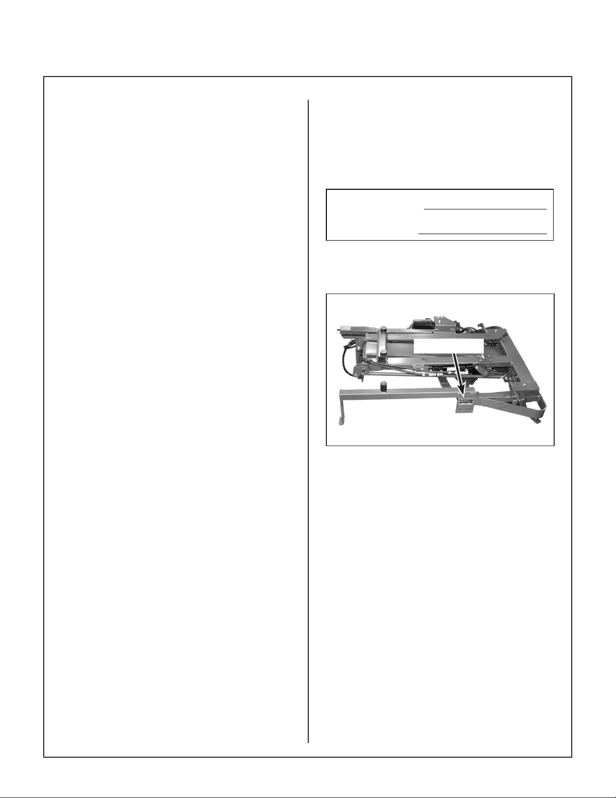
IDENTIFYING NUMBER LOCATIONS
The Hi-Dump® serial number is afxed to the LH
side of the main frame weldment. Model and serial
numbers are helpful when obtaining replacement
parts and maintenance assistance. For ready reference, please record these numbers in the space
provided.
Hi-Dump Serial No.
Date of Purchase
Refer to the Operator’s Manual that accompanies
the tractor for the location of the tractor serial number.
Serial Number
● GRASS HANDLING SYSTEM (GHS®) collects
mowed material and deposits it in the catcher.
● HI-DUMP® is a power lifting and dumping mech-
anism for the GHS catcher box controlled from
the operator’s seat.
● LEFT HAND (LH) refers to the left-hand side of
the tractor when the operator is seated facing
forward in the tractor seat.
● POWER TAKE-OFF (PTO) transmits engine
power to run the cutter blades and GHS blower.
● RIGHT HAND (RH) refers to the right-hand side
of the tractor when the operator is seated facing
forward in the tractor seat.
● STEERING LEVERS steer the tractor by con-
trolling the dual hydrostatic transmissions.
● TRACTOR is the prime mover, including the
engine, drivetrain, operator seat, and controls to
operate the mower.
A21 Hi-Dump Serial Number Location
(Top View)
1
Page 5

General Information
SERVICING OF HYDRAULIC POWER UNIT
Only routine maintenance and general service instructions are provided in this manual. For service
of the hydraulic power unit during the limited warran-
ty period, contact your authorized Walker dealer.
Any unauthorized work done on the hydraulic
power unit during the warranty period may void the
warranty. If you have any difculty nding an autho-
rized outlet or obtaining warranty service, please
contact our Service Department for assistance:
Walker Manufacturing Company
5925 E. Harmony Road
Fort Collins, CO 80528
1-970-221-5614
www.walker.com
UNIT DESCRIPTION
With the optional Hi-Dump® kit installed, the opera-
tor raises and dumps the GHS catcher box while
seated in the seat. Two toggle switches operate
independent hydraulic cylinders to raise, lower and
dump the catcher. The back door automatically
opens and closes during the dump cycle. The catcher may be dumped at any raised position (Normal
Operating-Intermediate-Fully Raised).
CONFIGURATION NOTE
When Hi-Dump® is installed, the optional single
wide tail wheel (P/N 8049) on the tractor is not rec-
ommended due to tail weight and extra turning resistance. Use the standard dual tail wheel (P/N 7420-
20).
2
Page 6

Specications
A21 HI-DUMP® KIT
MODEL A21
Catcher Lift Height in. (cm) 67 (170)
Maximum Lift Rating lb (kg) 200 (91)
Lift/Dump Cycle Time 20 seconds
Lift/Dump Controls Individual Toggle Switch with Solenoid Activated
Valves Operating Hydraulic Cylinders
Weight Installed lb (kg) 150 (68)
Height Increase (Tractor) in. (cm) 3 (8)
Hydraulic Oil Chevron Rykon Premium Oil ISO 68 or
Equivalent
Oil Capacity oz (L) 32 (.95)
NOTE: The manufacturer reserves the right to make changes in specications shown herein at any time without
notice or obligation.
3
Page 7

Safety Instructions
Pay particular attention to any information labeled
DANGER, WARNING, CAUTION, IMPORTANT,
and NOTE in this manual.
When you see the Safety Alert Symbol ( ), read,
understand, and follow the instructions. Fail ure to
comply with safety instructions may result in personal injury.
The seriousness or degree of importance of each
type of information is dened as follows:
DANGER
An IMMEDIATE hazard that WILL result in
severe personal injury or DEATH, if warning is ignored and proper safety precautions are not taken.
WARNING
A POTENTIAL hazard that COULD result in
severe personal injury or DEATH, if warning is ignored and proper safety precautions are not taken.
Walker Manufacturing cannot predict every potentially dangerous situation. Therefore, items labeled
as such in this manual do not cover all conceivable
situations. Any person using procedures, tools, or
control techniques not recommended by Walker
Manufacturing must take full responsibility for safety.
The Walker Rider Lawnmower has been designed
with many safety features to protect the operator
from personal harm or injury. However, it is necessary for the operator to use safe operating procedures at all times. Failure to follow safety instruc-
tions contained in this manual may result in
personal injury or damage to equipment or property.
If you have any questions concerning setup, operation, maintenance, or safety, please contact your
authorized Walker Mower dealer or call Walker Manufacturing Company at (970) 221-5614.
BEFORE OPERATING
1. Read and understand the contents of this
Operator’s Manual before starting and operating the machine. Become thoroughly famil-
iar with all machine controls and how to stop the
machine and disengage the controls quickly.
Replacement Operator’s Manuals are available
by sending the Model and Serial Number to:
Walker Manufacturing Company
5925 East Harmony Road
Fort Collins, CO 80528
CAUTION
Possible hazards or unsafe practices that
MAY result in MODERATE personal injury
or property damage, or machine damage, if
warning is ignored and proper safety precautions are not taken.
IMPORTANT: Identies mechanical information
demanding special attention, since it deals with the
possibility of damaging a part or parts of the machine.
NOTE: Identies information worthy of special
attention.
2. Never allow children to operate rider mower.
Do not allow adults to operate without proper
instruction.
3. Clear the area to be mowed of any foreign
objects which may be picked up and thrown by
cutter blades. Pick up all sticks, stones, wire,
and any other debris.
4. Keep everyone, especially children and pets, a
safe distance away from the area being mowed.
Do not mow with bystanders in the area.
5. Do not operate the machine barefoot or wearing
sandals, sneakers, tennis shoes, or similar
lightweight footwear. Wear substantial
protective footwear.
4
Page 8

Safety Instructions
6. Do not wear loose tting clothing that could get
caught in moving parts. Do not operate this ma chine while wearing shorts; always wear
adequate protective clothing, including long
pants. Wearing safety glasses, safety shoes,
and a helmet is advisable and required by some
local ordinances and insurance regulations.
7. Prolonged exposure to loud noise can cause
impairment or loss of hearing. Operator hear-
ing protection is recommended; particularly
for continuous operation of the GHS Model due
to blower noise level. Wear a suitable hearing
protective device, such as earmuffs or earplugs.
8. Keep all protective shields and safety de-
vices in place. If a protective shield, safety
device, or decal is damaged, unusable, or
missing, repair or replace it before operating
the machine.
9. Be sure interlock switches are functioning
correctly, so the engine cannot be started
unless the Forward Speed Control lever is in the
NEUTRAL-PARK position, the PTO clutch is in
the DISENGAGED position, and the Parking
Brake in the ENGAGED position. Also, the
engine should stop if the operator lifts off the
seat with any one or more of these controls
in the operating position: (1) Forward Speed
Control (FSC) out of NEUTRAL-PARK, (2)
PTO Clutch ENGAGED, or (3) Parking Brake
DISENGAGED.
11. Never attempt to make any adjustments
while the engine is running, except where
specically instructed to do so.
12. The electrical system battery contains sulfuric
acid. Avoid any contact with skin, eyes, and
clothing. Keep the battery and acid out of reach
of children.
WARNING
This product can expose you to chemicals
including Di-(2-ethylhexyl) phthalate which
is known to the State of California to cause
cancer, and Di-(2-ethylhexyl) phthalate,
which is known to the State of California
to cause birth defects or other reproductive harm. For more information go to
www.P65Warnings.ca.gov.
NOTE: There is a 1/2 second time delay func-
tion on the seat switch to avoid engine power
interruption when driving over bumps.
10. Handle gasoline with care. Gasoline is highly
ammable and its vapors are explosive:
a. Use an approved fuel container.
b. Never add fuel to a running engine or hot
engine (allow hot engine to cool several
minutes).
c. Keep matches, cigarettes, cigars, pipes,
open ames, or sparks away from the fuel
tank and fuel container.
d. Always ll the fuel tank outdoors using
care. Fill to about one inch from the top of
the tank. Use a funnel or spout to prevent
spilling.
e. Replace the machine fuel cap and contain-
er cap securely and clean up any spilled
fuel before starting the engine.
5
Page 9
Safety Instructions
OPERATING
1. Operate the machine only in daylight or in
good articial light with good visibility of areas
being mowed.
2. Sit on the seat when starting the engine and
operating the machine. Keep feet on the deck
footrests at all times when the tractor is moving
and/or the mower blades are operating. Never
operate the tractor without a deck or implement installed.
3. For a beginning operator, learn to steer (maneuver) the tractor with a slow engine speed
before attempting any mowing operation.
Be aware that, with the front mounted mower
conguration, the back of the machine swings
to the outside during turns.
DANGER
Do not operate around overhanging tree
branches or bushes at the same height as
the operator’s torso and head where inadvertent contact may cause injury.
7. Do not operate machine if the operator presence safety switch system is not working.
Verify proper operation by having the operator
lift off the seat with the engine running and moving three controls, one at a time; (1) Move the
FSC lever out of the NEUTRAL-PARK position,
(2) Engage the PTO Clutch, and (3) Disengage
the Parking Brake. Moving any of these controls should stop the engine after a 1/2 second
delay.
8. Do not run the engine in a conned area
without adequate ventilation. Exhaust fumes
are hazardous and can be deadly.
9. Do not carry passengers - maximum seating
capacity is one (1) person.
10. Watch for holes, rocks, and roots in the terrain
and for other hidden hazards. When mowing
tall grass, mow higher than desired to expose
any hidden obstacles. Then, clean the area
and mow to the desired height.
11. Avoid sudden starts or stops. Before back-
ing the machine up, look to the rear to be sure
no one is behind the machine. Watch carefully
for trafc when crossing or working near roadways.
4. Remember, for an emergency stop, the forward
motion of the tractor can always be stopped by
pulling the Forward Speed Control (FSC) into
the NEUTRAL-PARK position.
5. In case either of the transmission drive belts
break during operation, and if the machine is on
a slope, the machine will freewheel down the
slope. To maintain control, immediately (1)
Release the steering levers and simultaneously
(2) Move the FSC to the NEUTRAL-PARK po-
sition. When the machine is stopped or moving
slowly, engage the parking brake.
NOTE: The emergency stop procedure is exactly the same procedure used to normally stop
and park the machine.
6. Disengage the PTO clutch and put the FSC in
the NEUTRAL-PARK position before starting
the engine (an ignition interlock switch normally
prevents starting of the tractor if these controls
are in the OPERATING position).
12. When moving forward, do not suddenly put the
tractor in reverse by rapidly pulling on the steering levers, especially when going downhill, as
this can lift the tractor tail wheel off the ground
and set up a bucking motion due to operator
overcontrol. If bucking does occur, immediately
stop the bucking action by pulling the Forward
Speed Control (FSC) lever into the NEUTRAL-
PARK position.
13. Disengage the blade drive when transporting
the machine across drives, sidewalks, etc. Nev-
er raise the mower deck while blades are
rotating.
DANGER
Do not mow or dump grass within 5 feet
(1.5 meters) of an embankment or retaining
wall with drop off.
6
Page 10

Safety Instructions
14. The maximum recommended slope operating angle is 15 degrees or 26% grade. When
operating the machine on a slope, reduce speed
and use caution to start, stop, and maneuver.
To prevent tipping or loss of control of the machine, avoid sharp turns or sudden changes in
direction. Do not operate the machine on a
slope greater than 15 degrees.
15. Never adjust cutting height with the engine
running. Before adjusting cutting height or
servicing, disengage the blade clutch (PTO),
stop the engine, and remove the ignition key.
Wait for all movement to stop before getting off
the seat.
NOTE: A blade/blower brake should normally
stop drive line rotation within ve (5) seconds of
disengaging the PTO clutch.
16. For side discharge mower decks, do not oper-
ate with the grass deector shield removed.
Keep the deector in the lowest possible position.
17. When using the tilt-up deck, observe the fol-
lowing:
a. Do not move tractor with deck in tilt-up
position.
b. Never tilt body forward with deck in tilt-up
position.
18. For GHS equipped models, do not operate the
machine with the grass catcher in the DUMP
position or with the back door OPEN. Dan-
gerous projectiles may be thrown out of the discharge chute or the back of the grass catcher.
20. If the cutting blades strike a solid object or the
machine begins to vibrate abnormally, immedi-
ately disengage the blade clutch (PTO), stop
the engine, and wait for all moving parts to
stop. To prevent accidental starting, discon-
nect the spark plug wires. Thoroughly inspect
the mower and repair any damage before restarting the engine and operating the mower.
Make sure cutter blades are in good condition
and blade nuts are torqued to 60 lb·ft (81 N·m)
for gear driven decks, and blade bolts torqued
to 70 lb·ft (95 N·m) for belt driven decks.
21. Do not touch the engine or mufer while
the engine is running or immediately after
stop ping the engine. These areas may be hot
enough to cause serious burns.
22. When leaving the machine unattended, disen-
gage the blade clutch (PTO), stop the engine, and remove the key.
INSTRUCTIONS FOR HI-DUMP® OPERATION
1. When operating the Hi-Dump®, the operator
should be in the seat with feet on the footrests,
the FSC in NEUTRAL-PARK position and the
parking brake engaged.
2. To avoid tipping over, the tractor should be
parked on LEVEL GROUND when raising/
dumping the catcher with Hi-Dump®.
3. Make sure bystanders stay clear of the area
when the Hi-Dump® is operating.
4. Do not attempt to use the optional dump bag
or dump into any other bag with the Hi-Dump®.
19. In case of a clogged or plugged mower deck
or GHS catching system:
a. Disengage the blade clutch (PTO), engage
the parking brake, and turn the engine off
before leaving the seat.
b. LOOK to make sure blade drive shaft and
blower drive pulley movement has stopped
before trying to unclog the system.
c. Disconnect the spark plug wires.
d. Never place hands under the deck or in the
GHS blower - use a stick or similar tool to
remove clogged material.
7
Page 11

Safety Instructions
MAINTENANCE
1. To prevent accidental starting of the engine
when servicing or adjusting the machine, remove the key from the ignition switch and disconnect the fuel solenoid wire [diesel engines]
or the spark plug wire(s) [gasoline engines].
2. To reduce re hazards, keep the engine free
of grass, leaves, excessive grease, and dirt.
3. Keep all nuts, bolts, and screws tight to ensure
the machine is in a safe, working condition.
Check the blade mounting nuts frequently, making sure they are tight.
4. Perform only maintenance instructions de-
scribed in this manual. Unauthorized main-
tenance operations or machine modications
may result in unsafe operating conditions.
5. If the engine must be running to perform a main -
tenance adjustment, keep hands, feet and
clothing away from moving parts. Do not wear
jewelry or loose clothing.
6. Always use the proper engine service manual when working on the engine. Unautho-
rized maintenance operations or modications
to the engine may result in unsafe operating
conditions.
7. Altering the equipment or engine in any manner
which adversely affects its operation, performance, durability or use will VOID the warran-
ty and may cause hazardous conditions.
11. Use care when charging the battery or per-
forming maintenance on the battery and electrical system:
a. Make sure the battery charger is unplugged
before connecting or disconnecting cables
to the battery.
b. Charge the battery in a well-ventilated
space, so gases produced while charging
can dissipate. Make sure the battery vents
in the caps are open.
c. Keep sparks, ames, and smoking materi-
als away from the battery at all times. To
avoid sparks, use care when removing battery cables from posts.
d. Disconnect both battery cables before un-
plugging any wiring connectors or making
repairs on the electrical system.
12. Do not attempt to service the engine fuel injection system, which contains high pressure fuel
and may cause injury if mishandled. For service of the pressurized fuel system, including
the fuel pump module, fuel lines, and fuel injectors, contact your Walker dealer or authorized
Kohler service dealer.
IMPORTANT: Keep all applicable manuals immediately accessible to anyone who may operate or service this machine.
8. Never attempt to disconnect any safety devices
or defeat the purpose of these safety devices.
9. Do not change the engine governor settings or
overspeed the engine. The governor has been
factory-set for maximum-safe engine operating
speed.
10. Use genuine factory replacement parts.
Substitute parts may result in product malfunc-
tion and possible injury to the operator and/or
others.
INSTRUCTIONS FOR HI-DUMP® MAINTENANCE
1. When the Hi-Dump® is in the RAISED position
for access to the engine or drivetrain, ALWAYS
ENGAGE the safety lock before service or repair work. Remember to DISENGAGE the lock
before resuming operation of the Hi-Dump® (to
avoid damaging the lock mechanism).
2. With the Hi-Dump® in the normal operating position (catcher down), the catcher cannot be
manually raised. In the case of a dead battery,
use the auxiliary power terminals to charge/
boost the battery to raise the Hi-Dump®.
8
Page 12

SAFETY, CONTROL, AND INSTRUCTION DECALS
Safety, Control, and Instruction Decals are installed on the machine;
if any are missing, illegible, or damaged, a replacement should be ordered and installed before
putting the machine into operation. The Decal Part Number is listed below and in the Parts Manual.
8600-5
Safety Decal: Decal, Engine Exhaust
Location: LH Side of Chassis
Part Number: 8600-5
Operation Decal: Hi-Dump® Operation
Location: Switch Cover
Part Number: 8400-9
Safety Decal: Auxiliary Power Terminals
Location: Auxiliary Power Terminal Plate
Part Number: 8400-7
EQUIPPED
WITH
8400-16
HI-DUMP
Decal: Decal, Hi-Dump®
Location: Rear Bumper
Part Number: 8400-16
9
Safety Decal: Safety Lockout Arm
Location: Lower Lift Arm
Part Number: 8401-9
®
Page 13

Assembly Instructions
INSTALLING A21 HI-DUMP® ON THE TRACTOR
1. Disconnect battery. Always disconnect the neg-
ative (-) terminal rst.
2. Unplug catcher harness at the rear of the
catcher box. Unbolt the gas spring at both
ends. Remove the catcher assembly—retain
the hardware, as it will be reused.
NOTE: If installing on tractor with Power Dump,
remove actuator, mount, electrical harness and
switch.
NOTE: This step will be more easily accomplished with the help of an assistant.
3. Remove the body chute from the tractor body.
Install the new (longer) body chute.
NOTE: If installed on a tractor equipped with a
10 in. blower, order body chute, P/N 8430. If
installed on a tractor equipped with a 10-1/2 in.
blower, use body chute 8430-1 (included).
NOTE: It may be necessary to enlarge the hole
in the body in order for the chute to t.
4. FOR LIQUID COOLED UNITS ONLY: Remove
the coolant recovery tank from the mount. Remove tank mount from the bumper—retain the
hardware, as it will be reused.
and remove the instrument panel guard—retain
all hardware, as it will be reused.
8. Remove the precleaner tube. Loosen hose
clamp and remove three (3) shock mount
nuts (two in front, one in rear); retain the
hardware, as it will be reused.
9. Remove the two (2) nuts that attach the precleaner tube support arm to the fuel tank
strap (chassis) and remove and discard the
precleaner tube support arm. Push bolts back
against the fuel tank but do not remove the bolts
or the PTO Blade Clutch Mount.
NOTE: For Model T25i only, remove two bolts
mounting fuel pump module on rear upright
bracket and stow pump assembly to the side.
10. Grind paint around the hole in the jackshaft
mount to expose metal for ground (black wire)
as shown in Grind Paint on Jackshaft Mount
photo.
Grind Paint around Hole
on Jackshaft Mount
5. Remove rear bumper and discard—retain the
hardware, as it will be reused.
6. Remove the two (2) body bumpers mounted
on the back of the front body that the catcher
contacts when lowered. Install new bumper
(P/N 7847) on the right side, as shown in Install
Body Bumper photo.
Body Bumper
P/N 7847
Install Body Bumper
7. Unbolt the instrument panel from the chassis,
Grind Paint on Jackshaft Mount
11. FOR AIR-COOLED MODELS ONLY: Use a
pipe clamp to keep the chassis uprights from
spreading to ease installation, as shown in
Install Pipe Clamp to Keep Chassis from
Spreading photo.
(See photo on next page)
10
Page 14

Assembly Instructions
Pipe Clamp
LH Chassis
Upright
Install Pipe Clamp to Keep Chassis Uprights
from Spreading
12. Carefully, set the Hi-Dump® assembly on the
chassis being careful not to knock the PTO
Blade Clutch Mount loose (off of the mounting
bolts, RH side). Make sure the Hi-Dump® wire
harness is not damaged as the assembly is
positioned on the chassis frame.
RH Chassis
Upright
15. Route the harness under the chassis, and back
up in front of the PTO safety switch. Remove
and discard small cable clamp and replace with
larger clamp (P/N 5832). Install clamp using the
10-24 x 7/8 (F418) screw and the 10-24 (F002)
keps nut as shown in Install Cable Clamp to
PTO Safety Switch Mount photo being sure
to capture the PTO safety switch wires in the
cable clamp.
IMPORTANT: To avoid damage to the wire
harness, be sure the wire harness is pulled
snug under the chassis.
Wire Harness Routed
Under Chassis
Install Cable Clamp
P/N 5832
NOTE: This step will be more easily accomplished with the help of an assistant, or a well-
balanced lift/hoist.
13. If a pipe clamp was used, it can now be removed.
14. Using a at head screw driver, push the two
(2) bolts (partially removed in step 9) through
the fuel tank saddle and install the Hi-Dump®
spacer (P/N 8400-77) over the bolts, then the
Hi-Dump® frame upright. Reinstall nuts, and
tighten securely, as shown in Install RH Hi-
Dump® Frame photo.
NOTE: The spacer (P/N 8400-77) is not used
on the MT30i.
Hi-Dump
Frame Upright
PTO Blade
Clutch Mount
Install Cable Clamp to PTO Safety Switch Mount
16. Mount new relay switch (P/N 6941-8) and
bracket with one 10-24 x 1/2 (F026) screw,
one 1/4 star lock washer (F185), and one 10-
24 (F002) keps nut to the jackshaft mount as
shown in Install Relay Switch illustration.
RED
F026
F185
G
To
Time Delay
Harness
F002
Jackshaft
Assembly (Ref)
11
Spacer P/N
8400-77
Install RH Hi-Dump® Frame
Mounting
Bolt
Install Relay Switch
Page 15

Assembly Instructions
17. Plug the wire harness into the relay and run
the Hi-Dump® harness along the tractor’s main
harness to the battery as shown in Route Wire
Harness photo. Use three 7 in. cable ties to
hold in place. Plug connector on relay harness
into connector on time delay harness.
NOTE: It is recommended to use dielectric
grease on the wire harness connectors to ensure a good connection, and to prevent dust
and moisture from entering the plugs.
Wire Harness
Route Wire Harness
18. Connect the battery cables and the Red (+) and
Black (-) leads of the Hi-Dump® to the battery.
Connect the Red (+) rst.
NOTE: Connect the positive (+) leads rst.
Install a 4 in. cable tie, on both battery terminal
insulators.
19. Clamp the left front Hi-Dump® mount (at the
instrument panel guard mount point) ush with
the chassis using a c-clamp as shown in Clamp
LH Front Hi-Dump® Mount photo. Install the
5/16-18 x 3/4 (F034) hex bolt and the 5/16-18
(F009) whiz locknut. Reinstall the instrument
panel and panel guard using existing hardware
removed earlier.
NOTE: If the Hi-Dump® mounting hole is not
present in the chassis, it will be necessary to
drill a 5/16 in. hole using the Hi-Dump® mount
as a guide. Install hardware through the Hi-
Dump® frame and tractor chassis and hand
tighten.
20. Turn the ignition switch to the ON (RUN) position
and use the LIFT control switch to raise the HiDump® to the full UP position.
21. Using a tapered (drift) punch, align the left-rear
Hi-Dump® mounting holes to the chassis as
shown in Align Mounting Holes photo. Using
existing hardware, install bolt and nut in the
front hole and hand tighten. Remove punch and
install second nut and bolt. Leave bolts loose,
DO NOT tighten.
Tapered Punch
Align Mounting Holes
22. Using the tapered punch in the lower hole of
the rear upright mount in front of tailwheel pivot
housing, align the top hole as shown in Install
Hardware in Rear Upright Mount illustration
and install hardware.
IMPORTANT: To avoid damage, top bolt
(carriage head, F420) must be installed with
head towards hydraulic cylinder.
Clamp LH Front Hi-Dump® Mount
Tail Wheel Pivot
Housing (Ref)
Rear Upright
Mount Bolts
Install Hardware in Rear Upright Mount
Carriage Bolt
Installed With Head
Toward Cylinder
Rear Upright
Mount
12
Page 16

Assembly Instructions
NOTE: If there is a gap between the rear
upright mount and the chassis frame, install the
optional shim (P/N 8400-39) for best t.
NOTE: For Model T25i only, reinstall the fuel
pump module at the same time.
23. Using the tapered punch align the front holes
of the right rear mount holes and install a bolt
(from the inside to outside) through the rear
precleaner mount, Hi-Dump® and chassis. Install
nut nger tight. Remove the tapered punch and
install a bolt (from outside to inside) through the
front mount holes of the chassis, Hi-Dump® and
rear precleaner mount and install nut nger tight
(using existing hardware removed earlier).
24. Using the tapered punch, align the holes where
the two (2) bumper upright supports connect
to the chassis and install existing hardware, as
shown in Align Bumper Upright Supports to
Chassis photo.
IMPORTANT: A production change was made
at tractor S/N 2018-151222, and A21 S/N 20185402 that enlarged the hole from 3/8 in. to 7/16
in. It is possible that the Hi-Dump® kit bumper
and the tractor chassis could have differing hole
dimensions. If hole dimensions are different,
drill the smaller hole to 7/16 in.
28. Place the catcher assembly on the Hi-Dump®
frame as shown in Install Catcher Box As-
sembly photo.
Catcher Pivot Points
Outside Hi-Dump® Frame
Install Catcher Box Assembly
29. Install the two (2) new catcher pivot plates (P/N
7517-3), as shown in Install Catcher Pivot
Plates illustration. Hand tighten the bolts and
nuts reusing existing hardware.
Bumper Upright
Support
Tapered Punch
Used to Align
Mount Hole
Align Bumper Upright Supports to Chassis
25. Tighten all bolts and nuts.
26. Reinstall the precleaner tube and hose, using
existing hardware. Ensure hose clamps are
tight.
27. Lower the front body. Turn the ignition switch
to the ON (RUN) position and use the lift control switch to lower the Hi-Dump® to within
6-8 in. (15-20 cm) of the DOWN position.
Catcher Pivot
Plate
F038
Install Catcher Pivot Plates
30. Using the LIFT switch, lower the assembly to
the full down position. Align the catcher box to
the GHS body chute (blower discharge chute).
Make sure there is clearance on all sides.
Tighten the catcher pivot plate hardware installed in the previous step.
31. Attach the RH and LH channel angles (P/N
8404-12 and 8404-13) to the catcher frame
support with the two (2) 1/4-20 x 1/2 (F029)
hex bolts and two (2) 1/4-20 (F004) keps nuts
attaching the front of the channel nger tight.
F041
13
Page 17

Assembly Instructions
DRILL 3/8" DIA. THRU. TYP .2
1/4" TYP .2
4" TYP .2
FRONT OF CATCHER BOX
VIEW FROM BOTTOM OF CATCHER BOX
REAR OF CATCHER BOX
NOTE: The channel angle with the ball stud
mount attaches to the left side.
RH Channel
Angle
LH Channel
Angle
Ball Stud on
Channel Angle
Install Power Dump Arm Channel Angles
32. For installing the power dump cables (P/N
8623-2), drill two (2) 3/8 in. holes approximately
1/4 in. inside the radius of the catcher box
and 4 in. from the opening of the catcher box
as shown in Drilling Dimensions for Power
Dump Cables photo.
Front of Catcher Box
34. Remove existing lower arms (outside of catcher
box) and install new Lower Power Dump Arms
(P/N 8607-10) on both sides.
35. Install new inner power dump arms (P/N
8623-6 RH and P/N 8623-7 LH) on both sides
and orient each one as shown in Inner Power
Dump Arm photo.
Inner Power
Dump Arm
Install Inner Power Dump Arm
36. Assemble door springs to spring hooks (attached to torsion bar) and attach extension
spring clevis end to inner power dump arm, as
shown in Assemble Door Springs to Spring
Hooks and Attach Extension Spring Clevis
illustration.
4 in.*
1/4 in.*
Rear of Catcher Box
* Typical Two Places
View from Bottom of Catcher Box
Drill 3/8 in Dia.
Hole*
Drilling Dimensions for Power Dump Cables
33. Remove the cotter pins on both ends of the
torsion bar (inside catcher box). Insert spring
hook ends on both ends of torsion bar and
reinstall bar with new cotter pins.
(See next page)
14
Page 18

Assembly Instructions
7 1/2”1 5/16”
DRILL 3/16” DIA.
HOLES
8”
Lower Arm
P/N 8608-9
Torsion Bar
Drill 3/16 in.
Holes
Cable Guide
Extension
Spring Cable
Inner Power
Dump Arm
Hole in
Catcher Box
Hi-Dump®
Frame
Spring Hook
on Torsion Bar
Cable Guide
Cable
Assembly
Ball Joint
Assemble Door Springs to Spring Hooks and
Attach Extension Spring Clevis
37. Attach cable assembly to inner power dump
arms with clevis pin, as shown in Assemble
Door Springs to Spring Hooks and Attach
Extension Spring Clevis illustration. Install
threaded end of cable assembly through each
hole. Attach ball joints to cable ends. Attach
ball joints to Hi-Dump® frame bracket.
38. Tilt the catcher to the full back position using
the DUMP switch. Check the tension of both
cables. The tension should be equal. Adjust
accordingly with the ball joints. Tighten the jam
nuts.
39. Drill holes in both sides of the catcher box
(as shown in Drilling Dimensions for Cable
Guide Installation) to install cable guides (P/N
7620-6) inside catcher.
8 in.
1-5/16 in.
7-1/2 in.
Drilling Dimensions for Cable Guide Installation
40. Install guides on both sides, using the two (2)
10-24 x 3/4 (F028) screws, two (2) 3/16 Rivet
Backup Washer (F085), and two (2) 10-24
(F002) keps nuts as shown in Install Cable
Guides photo.
Cable Guide
Install Cable Guides
41. Plug the grass catcher harness into the main
harness. With the ignition switch in the ON
(RUN) position and the PTO engaged, check
the operation of the Powerl®.
15
Page 19

Assembly Instructions
NOTE: Check that the spout is oscillating and
the Grass-Pak® switch triggers the Full Signal
Horn to sound when the vane is pushed toward
the LH direction while oscillating.
42. FOR LIQUID-COOLED MODELS ONLY:
Remount the coolant recovery tank using the
new mount plate and hardware provided. Tie
the hose to the frame using two 7 in. cable ties.
Make sure the cable ties are not so tight as to
restrict coolant from owing through the hose.
NOTE: It may be necessary to shorten the
recovery tank hose by approximately 3 in. (7.6
cm)
43. Check the lift operation of the Hi-Dump®. The
front pivot should lift approximately 1 in. (2.5
cm) before the rear starts to rise as shown in
Check Lift Operation photo. If this does not
occur the control rods will need to be adjusted.
Catcher Box
Mount Frame
Hi-Dump
Frame
NOTE: The control rods and ball joints have
RH and LH threads. They can be adjusted by
loosening the jam nuts and turning the rod.
If the front of the catcher raises more than 1 in.
(2.5 cm) before the back raises, shorten the
control rods. The rods need to be adjusted
equally. If the back of the box raises before
the front raises 1 in. (2.5 cm) or the back of the
box is slightly raised in the full down position
(not contacting the rear bumpers), lengthen the
control rods. The rods need to be adjusted
equally.
Front Pivot Raises
1 in. Before Rear
Raises
Check Lift Operation
Catcher
Box
Front Pivot
44. Use the LIFT and DUMP control switches to
make sure the system operates properly.
16
Page 20

Operating Instructions
HI-DUMP® OPERATION
The operator raises and dumps the GHS catcher
box while sitting in the seat. Two toggle switches
operate independent hydraulic cylinders to raise,
lower, and dump the catcher. The back door automatically opens and closes during the dump cycle.
NOTE: The ignition switch must be in the ON (RUN)
position for the Hi-Dump® system to operate.
Toggle Switch
(Lift)
(+) Auxiliary
Power Terminal
NOTE: With the Hi-Dump® mechanism in the nor-
mal operating position (catcher down), the catcher
can be manually raised. In the case of a dead
battery, use the auxiliary power terminals to charge/
boost the battery to operate the Hi-Dump®.
CAUTION
The operator should be in the seat with the
machine in the NEUTRAL-PARK Position
and the parking brake engaged and bystanders stay clear when the Hi-Dump® is
operating. To avoid tipping over, the
machine should be parked on LEVEL
GROUND when raising/dumping the catcher with Hi-Dump®. Do not attempt to use
the optional dump bag or any other bag
with the Hi-Dump®.
WARNING
Toggle Switch
(Dump)
(-) Auxiliary
Power Terminal
Lift/Dump Control Switches and
Auxiliary Power Terminals
Hold the Lift toggle switch UP or DOWN to RAISE
or LOWER the catcher. Hold the Dump toggle
switch UP to DUMP the catcher and DOWN to return to the normal operating position. The catcher
may be dumped at any raised position (Normal Operating - Intermediate - Fully Raised).
NOTE: If grass tends to hang up in the catcher
after raising the catcher with the Hi-Dump®, “jiggle”
the steering levers and make the tractor bounce a
little to unstick the grass and make it slide out of the
catcher.
When the Hi-Dump® is in the RAISED position for access to the engine and drivetrain,
always ENGAGE the safety lock before service or repair work. Remember to DISENGAGE the lock before resuming operation
of the Hi-Dump® (to avoid damaging the
lock mechanism).
Safety Lockout
Arm Engaged
Safety Lockout Arm Engaged Position
17
Page 21

Operating Instructions
Safety Lockout
Arm Stowed
Safety Lockout Arm Disengaged Position
18
Page 22

Maintenance Instructions
CHECKING OIL LEVEL
To check the oil in the hydraulic power unit, remove
the plug from the unit and insert an allen wrench (as
a dipstick) until it touches the reservoir mounting bolt
that runs through the center of the reservoir. Oil level should be approximately 1/2 in. to 3/4 in. above
the bolt. To add hydraulic oil, use Chevron Rykon
Premium Oil ISO 68 or equivalent. System capacity
is 32 oz. (.95 liters)*.
NOTE: To completely ll, or rell, the hydraulic
system, DO NOT ll with 32 oz. initially. When ll-
ing, add about 22 oz., operate the system and allow
oil to ow throughout the system. Then, continue
lling the reservoir with the additional 10 oz.
LUBRICATION
WARNING
DO NOT attempt to lubricate the machine
with the tractor engine running. Disengage
the PTO clutch, shut off the machine, and
remove the ignition key.
Proper lubrication is an important maintenance procedure. It reduces wear and makes the machine
quieter and easier to operate.
NOTE: Tractor Lubrication Points are not shown
here. For Tractor Lubrication Points, refer to your
Tractor’s Operator’s Manual. If you do not have an
Operator’s Manual, you can download a copy at
www.walker.com.
* 32 oz (0.95 liters) is capacity if system is completely empty
19
Page 23

Maintenance Instructions
Ident Lubrication No.
No. Location Type Places
1 Hi-Dump® Catcher Frame Grease 2
2 LH/RH Rear Pivots Grease 2
3 Catcher Pivot Arm Grease 1
4 Hydraulic Power Unit Oil 1
1
3
4
2
2
A21 Lubrication Points Diagram
20
Page 24

Maintenance Instructions
ADJUSTMENTS
Catcher Box Clearance with Body Chute
● Using the LIFT switch, lower the catcher assem-
bly to the full down position. Check alignment of
the catcher box to the GHS body chute (blower
discharge chute). Make sure there is clearance
on all sides.
● To adjust clearance, loosen the bolts on both of
the catcher pivot plates (P/N 7517-3) and position the catcher for proper clearnace with the
body chute. Re-tighten the pivot plate bolts.
Door Opening Cable Tension
● Tilt the catcher to the full back position using the
DUMP switch. Check the tension of both cables.
The tension should be equal. Adjust accordingly
with the ball joints. Tighten the jam nuts.
Control Lift Rod
● Check the lift operation of the Hi-Dump®. The
front pivot should lift approximately 1 in. (2.5
cm) before the rear starts to rise as shown in
Check Lift Operation photo. If this does not
occur the control rods will need to be adjusted.
Catcher Box
Mount Frame
Hi-Dump
Frame
NOTE: The control rods and ball joints have
RH and LH threads. They can be adjusted by
loosening the jam nuts and turning the rod.
If the front of the catcher raises more than 1 in.
(2.5 cm) before the back raises, shorten the
control rods. The rods need to be adjusted
equally. If the back of the box raises before
the front raises 1 in. (2.5 cm) or the back of the
box is slightly raised in the full down position
(not contacting the rear bumpers), lengthen the
control rods. The rods need to be adjusted
equally.
Front Pivot Raises
1 in. Before Rear
Raises
Check Lift Operation
Catcher
Box
Front Pivot
21
Page 25

This page left intentionally blank
22
Page 26

A21 HI-DUMP® ASSEMBLY
ITEM PART DESCRIPTION NO.
NO. NO. REQ’D
A21 Hi-Dump Kit/10.0
1 8607-10 Lower Arm, Power Dump 2
2 7620-3 Pivot Bushing (1/2 x 9/16) 4
3 7523-2 Clevis Pin W/Hole (1/4 x 5/8) 4
4 8623-6 Inner Power Dump Arm, RH 1
5 8623-3 Extension Spring Cable 2
6 5221-2 Ext Spring (3/4 x 3-1/2”) 2
7 8623-5 Torsion Spring Hook 2
8 8623-7 Inner Power Dump Arm, LH 1
9 7620-6 Cable Guide 2
10 8623-2 Power Dump Cable, 10.0 2
11 5552 Ball Joint (1/4-28) 2
12 8402-3 Backup Plate 1
13 8404-12 Channel Angle/RH 1
14 8404-13 Channel Angle/Hi-Dump/LH 1
15 5841 Retainer Washer (3/8 x 1-1/4) 4
16 8845 Rubber Bumper (30mm OD x 40mm) 3
5/16-18 Female
17 8404-6 Clevis Pin (1/2 x 1-1/2) 1
18 7517-3 Catcher Pivot Plate 2
19 7620-15 Roller Wheel 2
20 8402-9 Catcher Pivot Arm 1
(Includes Items # 19, 21, 55 & F562)
21 5830 Grease Fitting 5
22 8404-5 Clevis Pin (1/2 x 1-1/4) 1
23 8402-4 Upper Cylinder Mount Arm 1
24 8402-1 Catcher Frame/Hi-Dump 1
(Includes Items # 21 & 27)
25 7845-1 Rubber Bumper (1.375 x .750) 2
26 8401-4 Upper Pivot Shaft 1
27 8201-3 Fiberglide Bearing 4
28 8401-5 Pivot Arm (Includes Item # 29) 1
29 8401-9 Decal, Safety Lockout Arm 1
30 5683 Pivot Bearing 2
31 8401-1 Torsion Spring (1-1/2) 1
32 8401-6 Spring Bushing 1
33 8401-3 Safety Lockout Arm 1
34 8401-2 Safety Lockout Spring 1
35 8400-3 Rear Pivot/LH 1
(Includes Items # 21 & 30)
36 5214-10 Ball Joint (1/2-20) Hi Strength 2
37 8400-16 Decal, Hi-Dump 1
38 7047-5 Mount Plate 1**
39 8404-7 MTL Adapter Bracket 1*
40 8430-1 Body Chute, Hi-Dump (10.5) 1
41 8400-10 Auxiliary Power Terminal Plate 1
(Includes Item # 42)
42 8400-7 Decal, Electrical Jumper Warning 1
43 8600-23 Decal, Danger/Body Latch 1
44 8400-19 Switch Mount 1
45 8400-9 Decal, Hi-Dump Operation 1
46 8400-14 Switch Cover (Includes Item # 45) 1
47 8401-13 Bumper/Hi-Dump Mount 1
(Includes Item # 37)
48 7854 Plastic Tip, Red 1
49 7383-2 Body Latch Hook 1
50 7847 Rubber Bumper (1.5 OD x 1.0) 1
51 8400-2 Rear Pivot/RH 1
(Includes Items # 21 & 30)
23
ITEM PART DESCRIPTION NO.
NO. NO. REQ’D
52 8402-8 Control Lift Rod 2
53 5214-11 Ball Joint (1/2-20LH) Hi Strength 2
54 8403-18 Pump Guard 1
55 7620-16 Roller Bushing 2
56 7031-4 Tube Support Arm/Hi-Dump 1
57 8400-77 Spacer/Hi-Dump 1***
58 8400-39 High Dump Upright Shim 1
Fasteners
F002 10-24 Keps Nut 10
F003 1/4-28 Hex Nut 2
F004 1/4-20 Keps Nut 8
F009 5/16-18 Whiz Locknut 15
F012 3/8-16 Keps Nut 12
F016 1/2-13 Self-Locking Nut 2
F025 10-24 x 3/8 PPHMS 1
F027 10-24 x 5/8 PPHMS 2
F028 10-24 x 3/4 PPHMS 4
F029 1/4-20 x 1/2 Hex Bolt 6
F034 5/16-18 x 3/4 Hex Bolt 6
F035 5/16-18 x 1-1/4 Hex Bolt 2
F037 10-24 x 5/8 PTH Screw 2
F038 3/8-16 x 1 Hex Bolt 6
F039 3/8-16 x 1-1/4 Hex Bolt 4
F040 3/8-16 x 1-1/2 Hex Bolt 3
F041 3/8-16 x 1-3/4 Hex Bolt 2
F048 1/2 SAE Washer 1
F049 5/16 SAE Washer 2
F052 5/16 Ext. Star Lock Washer 1
F068 1/8 x 1 Cotter Pin 2
F069 3/32 x 1/2 Cotter Pin 4
F085 3/16 Rivet Backup Washer 4
F111 1/8 x 3/4 Cotter Pin 2
F151 3/8-16 x 7/8 Hex Bolt 2
F183 .312 x .700 x .074 Washer 2
F208 5/16-18 x 2-1/4 Hex Bolt 5
F241 .375 x .875 x .10 Washer 6
F287 1/4-28 Keps Nut 2
F385 1/4 x 1-1/4 Roll Pin 1
F395 1/4-20 x 2-1/4 FHA Screw, SS 4
F396 10-24 x 1-1/4 PPH Bolt 2
F398 1/4-20 x 2 Hex Bolt 2*
F399 1/2-13 x 3-1/4 Hex Bolt 2
F402 1/4-20 x 2 PFH Bolt 2**
F405 3/8-16 x 1-1/2 FHA Screw, SS 1
F420 5/16-18 x 1-1/4 Carriage Bolt 1
F440 1/2-20 Jam Nut RH 2
F441 1/2-20 Jam Nut/Left Hand 2
F562 5/16-18 x 1 Set Screw 1
F570 3/8-16 Flange Top Lock Nut 4
* Model MTL Only
** Model MDD Only
*** Not Used on MT30i
∆ UseOptionalShimasNeededtoClose
Gap With Chassis Frame
Beginning S/N 2018-5524
Use only genuine Walker® replacement parts.
∆
Page 27

F396
F385
F009
F012
53
53
F441
52
F441
52
F012
F405
F040
F009
F034
F395
F069
F111
F034
F111
F241
F151
36
F040
F009
F208
F039
F440
F012
36
F034
F208
F016
F002
F012
F399
21
F035
F398
F402
F012
F012
F002
F009
F012
F009
F038
F009
F420
F025
F038
F037
44
42
47
46
F035
F009
F016
F048
F040
F009
F039
F399
F208
21
35
15
16
58
56
39
38
30
30
29
31
32
33
25
16
17
16
15
REUSE
REUSE
14
15
21
27
27
21
28
22
23
25
12
24
34
26
51
45
57
F002
F002
41
43
11
F003
F287
3
7
10
10
F069
F049
18
40
F009
REUSE
REUSE
50
48
49
50
F009
F034
54
F034
F052
F034
27
REUSE
REUSE
F562
F004
21
19
55
19
55
20
37
REUSE
F009
F420
58
CHASSIS
(REF)
47
(REF)
13
1
2
2
2
4
3
5
8
3
9
F085
F028
6
6
5
1
2
REUSE
REUSE
REUSE
7
F068
F069
F004
F004
F004
F004
F029
F029
F029
F002
F241
F570
F570
REUSE
F041
F038
F241
A21 HI-DUMP® ASSEMBLY
Beginning S/N 2018-5524
Use only genuine Walker® replacement parts.
24
Page 28

A21 HI-DUMP® HYDRAULIC AND ELECTRICAL COMPONENTS
ITEM PART DESCRIPTION NO.
NO. NO. REQ’D
Hi-Dump Kit – Hydraulic/Electrical
1 5833 Cable Clamp (1/4) 3
2 8440-1 Catcher Adapter Harness 1
3 8404 Dump Cylinder 1
4 8403-7 90° Fitting 12
5 5975-3 Cable Tie (50# x 7”) 1
6 8403-5 Hydraulic Hose, Catcher Box 1
Dump (67.5)
7 8403-6 Hydraulic Hose, Catcher Box 1
Dump (73.5)
8 5835 Cable Clamp (3/4) 6
9 8403-3 Hydraulic Hose, Lift/Rear (11.5) 1
10 8404-1 Lift Cylinder 1
11 8403-2 Hydraulic Hose, Lift/Front (16) 1
12 5975-7 Cable Tie (50# x 11”) 2
13 8404-2 Hydraulic Valve Box 1
14 8403-4 Hydraulic Hose, 1
Valve to Pump (17-1/2) A/UP
15 8403-20 Hydraulic Hose, 1
Valve to Pump (17-1/2) B/DN
16 5975-1 Cable Tie (18# x 3-3/4”) 11
17 8403-19 Hydraulic Power Unit 1
18 8440-7 Battery/Relay Harness 1
19 5832 Cable Clamp (1/2) 1
20 8401-7 Junction Block (10-32) 2
21 7941 Circuit Breaker 40 Amp 1
(Auto Reset/Sealed)
22 8404-9 Plastic Cover/Black 1
23 8404-8 Plastic Cover/Red 1
24 6623-22 Toggle Switch/SP 1
25 6623-21 Toggle Switch/DP 1
26 8440-3 Jumper Wire 1
27 8440-8 Wire Harness/Hi-Dump 1
28 7833 Cable Clamp (7/8 x 1/4) 1
29 8440-6 Relay Harness 1
30 8553 Splice Tap (18-14 Ga.) 1
31 8440-10 Wire Assembly (3”) 1
32 6941-8 Relay Switch 60/40 Amp 3
ITEM PART DESCRIPTION NO.
NO. NO. REQ’D
Fasteners
F002 10-24 Keps Nut 9
F004 1/4-20 Keps Nut 2
F025 10-24 x 3/8 PPHMS 11
F026 10-24 x 1/2 PPHMS 3
F027 10-24 x 5/8 PPHMS 4
F106 3/8-16 x 5/8 Hex Bolt 2
F185 1/4 Int. Star Lock Washer, SS 1
F232 10-32 Keps Nut 6
F397 1/4-20 x 3-3/8 Hex Bolt 2
F418 10-24 x 7/8 SHC Screw, GR5 (SS) 2
25
Beginning S/N 2018-5524
Use only genuine Walker® replacement parts.
Page 29

A21 HI-DUMP® HYDRAULIC AND ELECTRICAL COMPONENTS
F027
F418
23
22
19
To
Time Delay
Harness
F025
F002
25
RED
21
20
RED
RED
F002
16
F
F397
F026
32
16
16
F025
F397
28
1
4
CONNECT TO
RED WIRE
1
A
1
2
F025
F025
F025
F025
7
8
8
8
8
F025
6
F025
DETAIL A
3
4
4
5
5
GRN
DETAIL C
BLK
BLK
BLU
DETAIL B
BLK/WHTBLK/WHT
BLK
BLK
RED/YEL
RED/YEL
BLK
BLK
RED/YEL
DETAIL D DETAIL E DETAIL F
RED
RED
GRN
RED/YELBLU
RED
RED
RED/YEL
RED/YEL
8
DETAIL G
RED
BLK
31
INSERT RED WIRE
FROM 8440-7
RED
BLU
BLU
RED
RED
GRN
GRN
DETAIL H
BLK
BLK
RED
RED
GRN
GRN
BLK
BLK/WHTBLK/WHT
DETAIL I
RED
BLU
BLU
F026
32
H
I
F002
B
To
Pump
F106
C
F025
16
F025
15
14
4
13
F004
9
D
E
24
16
F232
26
F002
F232
BLK
16
29
BLK
18
32
G
F002
F026
F185
27
16
16
17
4
12
11
4
10
To
Harness
JACKSHAFT
ASSEMBLY
(FOR REFERENCE)
4
12
16
BLK
TRACTOR
CHASSIS
Beginning S/N 2018-5524
Use only genuine Walker® replacement parts.
30
CONNECTING 8440-10 to TIME DELAY HARNESS
To
Relay
Harness
END VIEWS ARE SHOWN FROM BACK OF PLUG
26
Page 30

MAINTENANCE AND SERVICE RECORD SHEET
DATE SERVICE ENGINE
ITEM HOURS
______________________________________________________________________________________________________________
______________________________________________________________________________________________________________
______________________________________________________________________________________________________________
______________________________________________________________________________________________________________
______________________________________________________________________________________________________________
______________________________________________________________________________________________________________
______________________________________________________________________________________________________________
______________________________________________________________________________________________________________
______________________________________________________________________________________________________________
______________________________________________________________________________________________________________
______________________________________________________________________________________________________________
______________________________________________________________________________________________________________
______________________________________________________________________________________________________________
______________________________________________________________________________________________________________
______________________________________________________________________________________________________________
______________________________________________________________________________________________________________
______________________________________________________________________________________________________________
______________________________________________________________________________________________________________
______________________________________________________________________________________________________________
______________________________________________________________________________________________________________
______________________________________________________________________________________________________________
______________________________________________________________________________________________________________
______________________________________________________________________________________________________________
______________________________________________________________________________________________________________
______________________________________________________________________________________________________________
______________________________________________________________________________________________________________
______________________________________________________________________________________________________________
______________________________________________________________________________________________________________
______________________________________________________________________________________________________________
______________________________________________________________________________________________________________
______________________________________________________________________________________________________________
______________________________________________________________________________________________________________
______________________________________________________________________________________________________________
______________________________________________________________________________________________________________
27
Page 31

LIMITED WARRANTY
FOR WALKER
A21 HI-DUMP
What this warranty covers, and for how long:
1.
Walker Manufacturing company will, at its option, repair or replace, without charge, any part covered
by this warranty which is found to be defective in material and/or workmanship within one (1) year after
date of sale to the original retail purchaser unless the product is used for rental purposes, in which case
this warranty is limited to ninety (90) days. At Walker’s request, customer will make the defective part
available for inspection by Walker and/or return the defective part to Walker, transportation charges
prepaid. All parts and components of the Walker Hi-Dump® are covered by this warranty.
What this warranty does not cover:
2.
A. This warranty does not cover defects caused by depreciation or damage caused by normal wear,
accidents, improper maintenance, improper use or abuse of the product, alterations, or failure to follow
the instructions contained in the Operator’s Manual for operation and maintenance.
B. The customer shall pay any charges for making service calls and/or for transporting the attachment
to and from the place where the inspection and/or warranty work is performed.
®
How to obtain service under this warranty:
3.
Warranty service can be arranged by contacting the dealer where you purchased the machine or by
contacting Walker Manufacturing Company, 5925 East Harmony Road, Ft. Collins, CO 80528. Proof of
the date of purchase may be required to verify warranty coverage.
Warranty limitation:
4.
A. THERE IS NO OTHER EXPRESS WARRANTY. ANY WARRANTY THAT MAY BE IMPLIED FROM THIS
PURCHASE INCLUDING MERCHANTABILITY AND FITNESS FOR A PARTICULAR PURPOSE IS HEREBY
LIMITED TO THE DURATION OF THIS WARRANTY AND TO THE EXTENT PERMITTED BY LAW ANY
AND ALL IMPLIED WARRANTIES ARE EXCLUDED. Some states do not allow limitations on how long an
implied warranty lasts, so the above limitations may not apply to you.
B. WALKER WILL NOT BE LIABLE FOR ANY INCIDENTAL, CONSEQUENTIAL, OR SPECIAL DAMAGES
AND/OR EXPENSES IN CONNECTION WITH THE PURCHASE OR USE OF THE MACHINE. Some
states do not allow the exclusion or limitation of incidental or consequential damages, so the above
limitation(s) or exclusion(s) may not apply to you.
C. Only the warranty expressed in this limited warranty shall apply and no dealer, distributor, or individual
is authorized to amend, modify, or extend this warranty in any way. Accordingly, additional statements
such as dealer advertising or presentations, whether oral or written, do not constitute warranties by
Walker, and should not be relied upon.
D. This warranty gives you specific legal rights, and you may also have other rights which vary from
state to state.
28
Page 32

WALKER MFG. CO. • 5925 E. HARMONY ROAD, FORT COLLINS, CO 80528 • (970) 221-5614
FORM NO. 111418 PRINTED IN USA www.walker.com ©2018 WALKER MFG. CO
 Loading...