

AGRI-VAC
3510
TOUGH TO BEAT IN THE LONG RUN
Model 3510
Gas and Electric
OPERATOR'S MANUAL
and PARTS BOOK

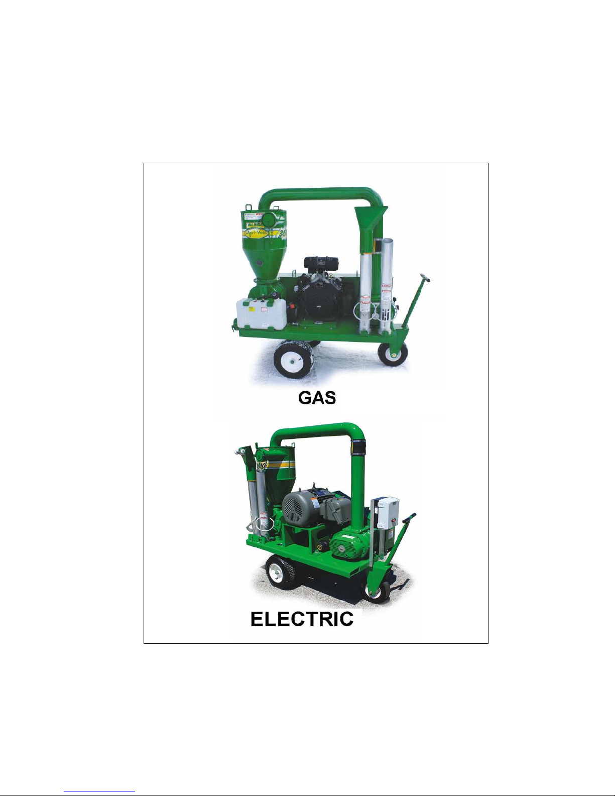
3510 AGRIVAC -VAC MODELS GAS & ELECTRIC
WARRANTY REGISTRATION (3 part form - please print)
Warranty Registration Form & Inspection Report
This form must be filled out by the dealer and signed by both the dealer and the customer at the time of delivery.
Delivery Date: mm / dd / yyyy
COMPANY / CUSTOMER NAME DEALER NAME:
Phone: Phone:
Mobile phone: Mobile phone:
Email : @ Email : @
Street Address: Street Address:
City: Prov/State City: Prov/State:
Postal/Zip: Country Postal/Zip: Country:
Machine Serial Number
Blower Serial No.
Airlock Serial Number
DEALER INSPECTION REPORT SAFETY
I have thoroughly instructed the buyer on the above described equipment which review included the Operator’s
Manual content, equipment care, adjustments, safe operation and applicable warranty policy.
Date ____________________Dealer's Rep. Signature _________________________________________
Blowers and Airlock Turn Freely
Air Line Connections Tight
Check Tire Pressure
Wheel Bolts Tight
Lubricate Machine
Check Oil Level in Reservoirs
Belts are Tight
O-Rings in Place
Guards Installed and Secured
All Safety Signs Installed
Reflectors and Signs Clean
Review Operating and Safety Instructions
Operating Manual Supplied
The above equipment and Operator’s Manual have been received by me and I have been thoroughly instructed as to
care, adjustments, safe operation and applicable warranty policy.
Date ___________________ Owner's Signature ________________________________________
199 05042016
3 Part Form
Please Print
WHITE YELLOW PINK
WALINGA DEALER CUSTOMER


Walinga Inc.
Pneumatic Conveying System
Warranty Terms
Walinga Inc. is committed to providing a quality product that will meet or exceed your expectations for many years
to come. Our warranty terms and our warranty claim process has been designed to ensure that each warranty claim
will be resolved in an orderly, fair and timely manner.
The Warranty
Walinga Inc. (“Walinga”) warrants that all new pneumatic products sold by Walinga Inc. will be free from defects in material
and workmanship (the “Walinga Warranty”).
Warranty Period
The warranty period for the Walinga Warranty shall expire on the date that is the earlier of: two (2) years after the date of
delivery to the original customer; or upon the expiration of five hundred (500) hours of operation; whichever date comes first.
Limitations of and exclusions from the Walinga Warranty
The Walinga Warranty applies to material and workmanship only.
With respect to any component parts that are supplied or manufactured by others, the warranty coverage on such
component parts will be strictly limited to the warranties of the manufacturers of such component parts.
The Walinga Warranty shall only be for the benefit of the original purchaser of the pneumatic products.
A Walinga Warranty may be transferable by the original purchaser to a third party for the balance of the warranty
period then remaining, provided that Walinga consents in writing to such transfer of warranty.
The Walinga Warranty is conditional upon proper storage, installation, use, maintenance, operation and compliance
with any applicable recommendations of Walinga.
Warranty Claim Procedure
Should you encounter any difficulties with your unit within its warranty period, please contact your local Walinga dealer or
sales representative, your local Walinga Service department or Walinga's Warranty Department to submit a warranty claim
application.
To speak with a Walinga Warranty Coordinator, contact:
Canada
International
USA
Australia
Required Warranty Claim information
The following information must be provided to Walinga in order for us to properly process and consider your warranty
application:
Customer name and contact information (email if available).
The equipment serial number and/or Vehicle Identification Number (if applicable).
Date of claimed failure.
Equipment hours of operation.
Details, description and photos (upon request) of the claimed failure and the corrective repairs attempted.
Warranty Conditions
Equipment must be registered within 30 days of being received by the buyer. It will be within the sole and
unfettered discretion of Walinga as to whether it will honour its warranty on non-registered equipment.
1-888-WALINGA (ext 273)
+1-519-824-8520 (ext 273)
Email – warranty.canada@walinga.com
1-800-466-1197 (ext 8)
Email – warranty.usa@walinga.com
07-4634-7344
Email – mail@customvac.com.au

Warranty Conditions (continued)
The buyer is responsible for promptly notifying Walinga of any defects to the equipment. The buyer is also
responsible for making the equipment available to Walinga or its authorized repair facility for evaluation and repair.
Prior to making any repairs or parts replacements, a warranty application and any estimated associated costs must
be approved with the issuance of a claim number by an authorized Walinga representative. Undertaking any work
prior to receiving warranty authorization may result in a partial or complete loss of warranty coverage.
At Walinga's discretion, warranty repairs may be authorized to be completed at a repair facility convenient to the
buyer. In such situations the estimated labour time must be approved by Walinga prior to undertaking any work.
Labour hours will be reimbursed at the facilities posted hourly labour rate.
At Walinga's request, parts in question must be returned to the nearest Walinga service facility for evaluation. In such
situations a Returned Goods Authorization (RGA) number will be provided to the buyer. The returning shipment must
be clearly labeled with the assigned RGA number and include a copy of the RGA form. Unless otherwise arranged,
these parts are to be returned to Walinga within 30 days to ensure timely processing of your warranty claim. Failure
to return such parts may result in partial or complete loss of warranty coverage.
Replacement parts provided under warranty are covered for the remainder of the original equipment warranty period.
Walinga reserves the right to use new, remanufactured or refurbished components when performing warranty repairs
and replacements.
Walinga is entitled to a reasonable amount of time and a reasonable number of attempts to assess the claim,
diagnose the problem, and perform any necessary repairs.
The warranty offered on used or refurbished equipment is limited to that specified on the purchase contract. Where a
warranty period has not been stipulated on the purchase contract., and where such equipment is “used”, then such
equipment is considered by Walinga to be sold “as is, where is” without the Walinga Warranty. Where such
equipment is refurbished, then the Walinga Warranty shall apply.
Without limitation, Walinga reserves the right to reject a warranty claim or for any one or more of the following
reasons:
The warranty claim information provided is insufficient.
The product evaluation does not substantiate the claim.
The unit has been operated above and beyond its capacity or not maintained or serviced properly, resulting in
damages incurred to major components.
If the unit was equipped with a factory installed hour meter which has been disconnected, altered or inoperative for
an extended period of time; with the result being that the equipment’s operating hours cannot be verified.
It is apparent that the operator’s manuals have not been followed.
The equipment is not registered.
Without limitation, Walinga’s Warranty does not cover:
Damage or deterioration due to lack of reasonable care or maintenance.
Damage caused or affected by unapproved modifications to the equipment.
Damage caused by negligence or misuse of the equipment.
Damage caused by using the equipment for purposes for which it was not designed or intended.
Walinga’s liability under this warranty, whether in contract or tort, is limited to the repair, replacement or adjustment of
defective materials and workmanship. In no event will Walinga be responsible for any direct, indirect, loss of time, incidental
or consequential expenses including, but not limited to, equipment rental expenses, towing, downtime, inconvenience, or any
losses resulting from the inability to use the equipment. Further, Walinga shall not be liable for any damages or
inconvenience caused by any delay in the supply or delivery of any equipment or component parts thereof.
The selling Dealer/Sales Person makes no warranty of its own and has no authority to make any representation or promise
on behalf of Walinga, or to modify the terms or limitations of the Walinga Warranty in any way.
Punitive, exemplary or multiple damages may not be recovered unless applicable law prohibits their disclaimer.
Warranty related claims may not be brought forward as a class representative, a private attorney general, a member of a
class of claimants or in any other representative capacity.
The Walinga Warranty and all questions regarding its enforceability and interpretation are governed by the law of the country,
state or province in which you purchased your Walinga equipment. The laws of some jurisdictions limit or do not allow the
disclaimer of consequential damages. If the laws of such a jurisdiction apply to any claim against Walinga, the limitations and
disclaimers contained here shall be to the greatest extent permitted by law.

Dear Customer,
Thank you for choosing WALINGA PNEUMATIC CONVEYING SYSTEMS. For your convenience, should you
require any information related to Parts, Service or Technical Engineering, please contact one of the
following Walinga Personnel in Guelph at 1-888 925-4642 unless noted
TECHNICAL - ENGINEERING:
Duane Swaving 226-979-8227 duane.swaving@walinga.com
Ken Swaving 519 787-8227 (ext:100) ks@walinga.com
WARRANTY CLAIMS:
Canada:
USA: Jonathan Medemblik
Kevin Vanderzwaag (273) warranty
(800) 466-1197 (ext 8) jtm@walinga.com
@walinga.com
SERVICE MANAGER:
Andy Nijenhuis (519) 763-7000 (ext:260) andy@walinga.com
SALES MANAGER:
Canada: Tom Linde (519) 787-8227 (ext 5) thl@walinga.com
USA: Peter Kingma (800) 466-1197 jpk@walinga.com
ORIGINAL PARTS SALES:
Ontario and Eastern Canada:
Scott
Lodder (ext: 224) sp
Parts Department Fax: (519) 824-0367
Manitoba and Western Canada:
Chad Yeo 204-745-2951 chad.yeo@walinga.com
USA: John VanMiddlekoop (800) 466-1197 (ext 3) jvm@walinga.com
l@walinga.com
CORPORATE HEAD OFFICE:
5656 Highway 6N
RR#5, Guelph, Ontario,N1H 6J2
PHONE: (888) 925-4642 FAX: (519) 824-5651
www.walinga.com
AGRI-VAC MANUFACTURING FACILITY:
938 Glengarry Cres., Fergus, Ontario Canada N1M 2W7
Tel: (519) 787-8227 Fax: (519) 787-8210
DISTRIBUTION AND SERVICE CENTRES:
5656 Highway 6N, Guelph, Ontario Canada, N1H 6J2
Tel: (888) 925-4642 FAX: (519) 824-5651
1190 Electric Ave. Wayland , MI.USA 49348
Tel: (800) 466-1197 Fax: (616) 877-3474
rd
70 3
Tel: (204) 745-2951 Fax: (204) 745-6309
24 Molloy Street, Toowoomba, Queensland Australia 4350
Tel: 07-4634-7344 mail@customvac.com.au
Ave. N.E. Box 1790 Carman, Manitoba Canada R0G 0J0
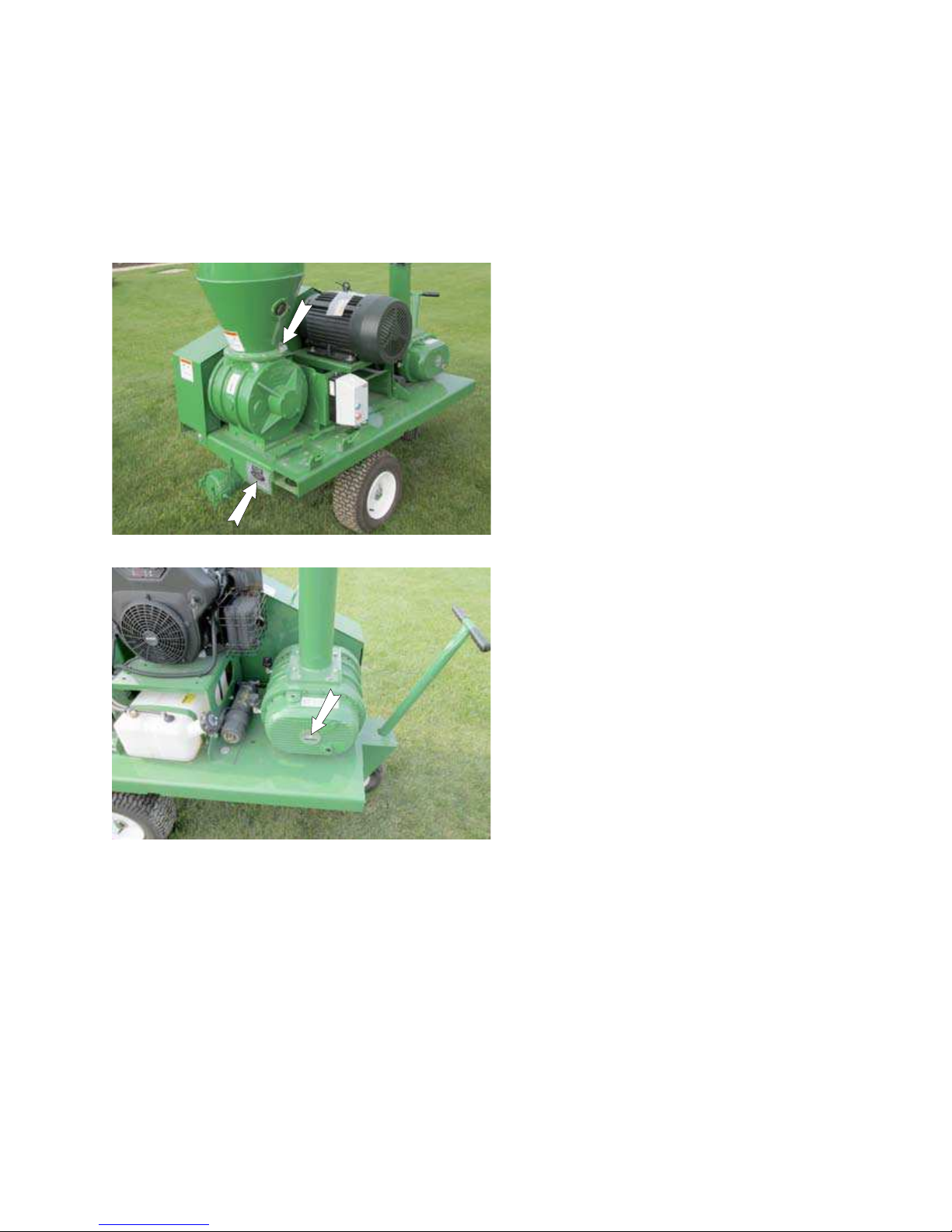
SERIAL NUMBER LOCATION
Always give your dealer the serial numbers of your Walinga
®
Inc. Agri-Vac® when ordering parts or requesting
service or other information.
Serial number plates are located where indicated. Please mark the numbers in the spaces provided for easy
reference.
SERIAL NUMBER LOCATION
Airlock Serial Number
__________________________________
Machine Serial Number
__________________________________
Blower Serial Number
__________________________________

NOTES:

TABLE OF CONTENTS
SECTION DESCRIPTION PAGE
1 Introduction ............................................................................1
4BGFUZ.......................................................................................2
2.1 General Safety ...............................................................3
2.2 Equipment Safety Guidelines.........................................4
2.3 Storage Safety ...............................................................4
2.4 Safety Training................................................................5
2.5 Safety Signs...................................................................5
2.6 Preparation.....................................................................6
2.7 Installation Safety...........................................................6
2.8 Lock-Out Tag-Out Safety................................................6
2.9 Operating Safety ............................................................7
2.10 Maintenance Safety .......................................................7
2.11 Electrical Safety .............................................................8
2.12 Transport Safety.............................................................8
2.13 Refueling Safety .............................................................8
2.14 Tire Safety ......................................................................8
2.15 Battery Safety.................................................................8
2.16 Gas Motor Safety ...........................................................9
2.17 Safety Around Bins, Silos, Tanks etc............................10
2.18 Employee Sign-Off Form.............................................. 11
4BGFUZ4JHO-PDBUJPOT..........................................................13
4 Operation...............................................................................17
4.1 To the New Operator or Owner ....................................17
4.2 Machine Components ..................................................18
4.3 Machine Break-In.........................................................19
4.4 Pre-Operation Checklist ...............................................19
4.5 Machine Preparation ....................................................20
4.6 Controls........................................................................21
4.7 Field Operation.............................................................23
4.8 Transport ......................................................................29
4.9 Storage.........................................................................30
4.10 Conveying Oilseeds......................................................30
4FSWJDFBOE.BJOUFOBODF....................................................31
5.1 Service .........................................................................31
5.2 Maintenance.................................................................37
6 Trouble Shooting..................................................................
7 Specications.......................................................................53
7.1 Mechanical...................................................................53
7.2 Bolt Torque ...................................................................54
8 Parts ......................................................................................55
*OEFY......................................................................................57
1 INTRODUCTION
Congratulations on your choice of a Walinga® Agri-Vac® to complement your operation. This equipment has been
designed and manufactured to meet the needs of the discriminating buyer for the efficient moving of grain.
Safe, efficient and trouble free operation of your new Walinga
who will be operating or maintaining the Agri-Vac
®
, read, understand and practice ALL of the Safety, Operation,
®
Agri-Vac® requires that you, and anyone else
Maintenance and Trouble Shooting recommendations contained within this Operator's Manual.
This manual applies to the Walinga
guide to nd required information.
OPERATOR ORIENTATION - The directions left, right, front and rear as mentioned throughout this manual are
when viewed from the airlock end of the machine. The steering handle is the front, drive system left and airlock
rear.
®
3510 gas or electric Agri-Vac®. Use the Table of Contents and Index as a
1

2 SAFETY
SAFETY ALERT SYMBOL
This Safety Alert symbol means
ATTENTION! BECOME ALERT! YOUR
SAFETY IS INVOLVED!
Why is SAFETY important to you?
3 Big Reasons
SIGNAL WORDS:
No t e th e use o f th e sign a l wo rds DANGER,
WARNING and CAUTION with the safety messages. The app ropriate signa l word for each
message has been selected using the following
guide-lines:
The Safety Alert symbol identifies
impor tant safety messages on the
Walinga
When you see this symbol, be alert
to the possibility of personal injury or
death. Follow the instructions in the
safety message.
®
Agri-Vac® and in the manual.
Accidents Disable and Kill
Accidents Cost
Accidents Can Be Avoided
DANGER
- Indicates an imminently hazardous
situation that, if not avoided, will result
in death or serious injury. This signal
word is to be limited to the most extreme situations typically for machine
components which, for functional purposes, cannot be guarded.
Keep this manual handy for frequent reference and to pass on to new operators or owners. Call your Walinga
dealer if you need assistance, information or additional copies of the manual.
Contact your dealer for a complete listing of parts.
2
WARNING - Indicates a potentially hazardous situ-
ation that, if not avoided, could result
in death or serious injury, and includes
hazards that are exposed when guards
are removed. It may also be used to
alert against unsafe practices.
CAUTION - Indicates a potentially hazardous situ-
ation that, if not avoided, may result in
minor or moderate injury. It may also
be used to alert against unsafe practices.
®

SAFETY
2.1 GENERAL SAFETY
YOU are responsible for the SAFE operation and
maintenance of your Walinga
®
Agri-Vac®. YOU must
ensure that you and anyone else who is going to
operate, maintain or work around the Agri-Vac
be familiar with the operating and maintenance
procedures and related SAFETY information
contained in this manual. This manual will take you
step-by-step through your working day and alerts you
to all good safety practices while operating the Agri-
®
Vac
.
Remember, YOU are the key to safety. Good safety
practices not only protect you but, also the people
around you. Make these practices a working part of
your safety program. Be certain that EVERYONE
operating this machine is familiar with the procedures
recommended and follows safety precautions.
Remember, most accidents can be prevented. Do
not risk injury or death by ignoring good safety
practices.
• Agri-Vac
®
owners must give operating instructions
to operators or employees before allowing them
to operate the machine, and at least annually
thereafter.
• The most important safety device on this equipment is a SAFE operator. It is the operator’s responsibility to read and understand ALL Safety
and Operating instructions in the manual and to
follow these. Most accidents can be avoided.
• A person who has not read and understood all operating and safety instructions is not qualied to
operate this machine. An untrained operator exposes himself and bystanders to possible serious
injury or death.
• Do not modify the equipment in any way.
Unauthorized modication may impair the function and/or safety and could aect the life of the
equipment.
1. Read and understand the
Operator’s Manual and all
safety signs before supplying
®
power, operating, maintaining ,
adjusting or unplugging.
2. Only trained, competent persons shall operate the
Agri-Vac
®
. An untrained operator is not qualied to
operate this machine.
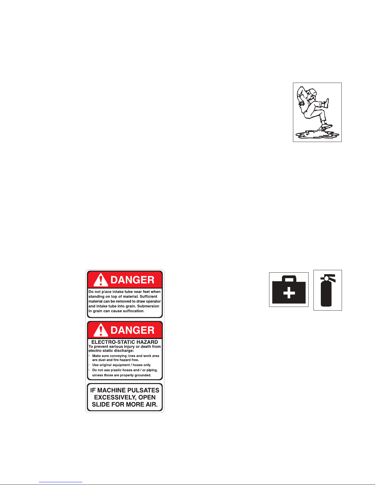
3. Provide a rst-aid kit for use in
case of an accident. Store in a
highly visible place.
4. Provide a re extinguisher for use in
case of an accident. Store in a highly
visible place.
5. Install and properly secure all guards
and shields before operating.
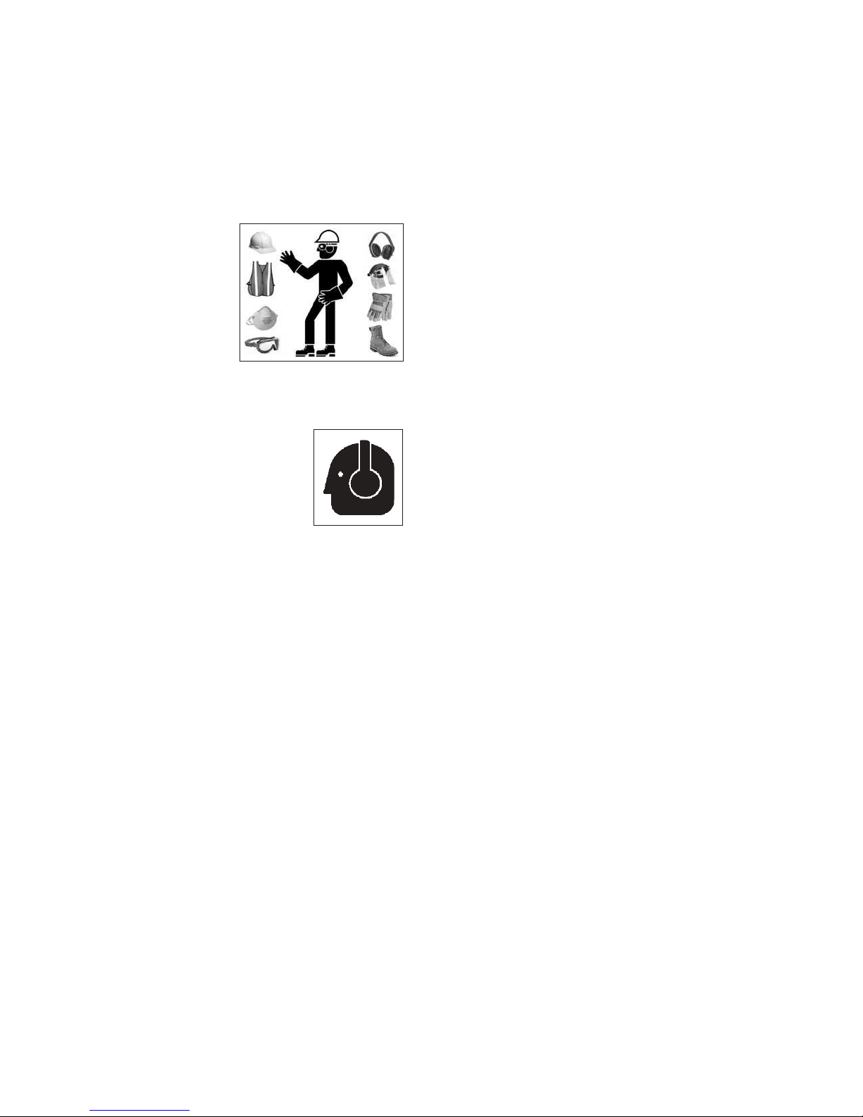
6. Wear appropriate protective gear. This list
includes but is not limited to:
- A hard hat
- Protective shoes
with slip resistant
soles
- Protective glasses or goggles
- Heavy gloves
- Wet weather gear
- Hearing protection
7. Turn machine OFF, shut down and lockout power
supply and wait for all moving parts to stop before servicing, adjusting, maintaining, repairing,
cleaning or unplugging. (Safety lockout devices
are available through your Walinga
®
dealer parts
department).
• Think SAFETY! Work SAFELY!
8. Know the emergency medical center number for
your area.
9. Wear appropriate hearing protection when operating the machine.
10. Review safety related items with all operators
annually.
3

2.2 EQUIPMENT SAFETY
GUIDELINES
1. Safety of the operator and bystanders is one of
the main concerns in designing and developing a
machine. However, every year many accidents occur which could have been avoided by a few seconds of thought and a more careful approach to
handling equipment. You, the operator, can avoid
many accidents by observing the following precautions in this section. To avoid personal injury or
death, study the following precautions and insist
those working with you, or for you, follow them.
2. In order to provide a better view, certain photo-
graphs or illustrations in this manual may show an
assembly with a safety shield removed. However,
equipment should never be operated in this condition. Keep all shields in place. If shield removal
becomes necessary for repairs, replace the shield
prior to use.
3. Replace any safety sign or instruction sign that is
not readable or is missing. Location of such safety
signs is indicated in this manual.
4. Never use alcoholic beverages or drugs which
can hinder alertness or coordination while operating this equipment. Consult your doctor about
operating this machine while taking prescription
medications.
5. Under no circumstances should young chil-
dren be allowed to work with this equipment.
Do not allow persons to operate or assemble
this unit until they have read this manual and
have developed a thorough understanding of
the safety precautions and of how it works.
Review the safety instructions with all users
annually.
6. This equipment is dangerous to children and
persons unfamiliar with its operation. The operator should be a responsible, properly trained and
physically able person familiar with farm machinery and trained in this equipment's operations.
If the elderly are assisting with farm work, their
physical limitations need to be recognized and
accommodated.
9. In addition to the design and conguration of this
implement, including Safety Signs and Safety
Equipment, hazard control and accident prevention are dependent upon the awareness, concern,
prudence, and proper training of personnel involved in the operation, transport, maintenance,
and storage of the machine. Refer also to Safety
Messages and operation instruction in each of the
appropriate sections of the auxiliary equipment
and machine Manuals. Pay close attention to the
Safety Signs axed to the auxiliary equipment
and the machine.
2.3 STORAGE SAFETY
1. Store the Agri-Vac® on a rm level surface.
2. If required, make sure the unit is rmly blocked
up.
3. Make certain that all mechanical locks are safely
and positively connected before storing.
4. Store away from areas of human activity.
5. Do not allow children to play on or around the
stored Agri-Vac
6. Lock out power by turning o master control panel
or junction box and padlocking the door shut to
prevent electrocution or unauthorized start up of
the Agri-Vac
7. Stop engine, remove ignition key and store in a
secure place for the gas model.
®
.
®
for the electric model.
7. Never exceed the limits of a piece of machinery. If
its ability to do a job, or to do so safely, is in question - DON'T TRY IT.
8. Do not modify the equipment in any way.
Unauthorized modication result in serious injury
or death and may impair the function and life of the
equipment.
4

2.4 SAFETY TRAINING
2.5 SAFETY SIGNS
1. Safety is a primary concern in the design and man-
ufacture of our products. Unfortunately, our eorts
to provide safe equipment can be wiped out by a
single careless act of an operator or bystander.
2. In addition to the design and conguration of
equipment, hazard control and accident prevention are dependent upon the awareness, concern, prudence and proper training of personnel
involved in the operation, transport, maintenance
and storage of this equipment.
3. It has been said, "The best
safety feature is an informed,
careful operator." We ask you
to be that kind of an operator.
It is the operator's responsibility
to read and understand ALL Safety and Operating
instructions in the manual and to follow these.
Accidents can be avoided.
4. Working with unfamiliar equipment can lead
to careless injuries. Read this manual, and the
manual for your auxiliary equipment, before
assembly or operating, to acquaint yourself
with the machines. If this machine is used by
any person other than yourself. It is the machine owner's responsibility to make certain
that the operator, prior to operating:
a. Reads and understands the operator's
manuals.
b. Is instructed in safe and proper use.
5. Know your controls and how to stop the Agri-Vac
and any other auxiliary equipment quickly in an
emergency. Read this manual and the one provided with your other equipment.
1. Keep safety signs clean and legible at all times.
2. Replace safety signs that are missing or have become illegible.
3. Replaced parts that displayed a safety sign should
also display the current sign.
4. Safety signs are available from your authorized
Distributor or Dealer Parts Department or the
factory.
How to Install Safety Signs:
• Be sure that the installation area is clean and dry.
• Be sure temperature is above 50°F (10°C).
• Determine exact position before you remove the
backing paper. (See Section 3).
• Remove the smallest portion of the split backing
paper.
• Align the sign over the specied area and carefully
press the small portion with the exposed sticky
backing in place.
• Slowly peel back the remaining paper and carefully smooth the remaining portion of the sign in
place.
• Small air pockets can be pierced with a pin and
smoothed out using the piece of sign backing
®
paper.
6. Train all new personnel and review instructions
frequently with existing workers. Be certain only
a properly trained and physically able person will
operate the machinery. A person who has not read
and understood all operating and safety instructions is not qualied to operate the machine. An
untrained operator exposes himself and bystanders to possible serious injury or death. If the elderly are assisting with work, their physical limitations
need to be recognized and accommodated.
5
2.6 PREPARATION
2.7 INSTALLATION SAFETY
1. Never operate the Agri-Vac® and auxiliary equipment until you have read and completely understand this manual, the auxiliary equipment
Operator's Manual, and each of the Safety
Messages found on the safety signs on the and
auxiliary equipment.
2. Personal protection
equipment including hard hat, safety glasses, safety
shoes, and gloves
are recommended
during assembly, installation, operation,
adjustment, maintaining, repairing, removal, or moving the implement. Do not allow long hair, loose tting clothing
or jewelery to be around equipment.
3. PROLONGED EXPOSURE
TO LOUD NOISE MAY CAUSE
PERMANENT HEARING LOSS!
Motors or equipment attached
can often be noisy enough to
cause permanent, partial hearing loss. We recommend that you wear hearing
protection on a full-time basis if the noise in the
Operator's position exceeds 80db. Noise over
85db on a long-term basis can cause severe hearing loss. Noise over 90db adjacent to the Operator
over a long-term basis may cause permanent,
total hearing loss. NOTE: Hearing loss from loud
noise (from tractors, chain saws, radios, and other
such sources close to the ear) is cumulative over
a lifetime without hope of natural recovery.
4. Clear working area of debris, trash or hidden obstacles that might be hooked or snagged, causing
injury, damage or tripping.
5. Operate only in daylight or good articial light.
6. Be sure machine is properly anchored, adjusted
and in good operating condition.
7. Ensure that all safety shielding and safety signs
are properly installed and in good condition.
1. Disconnect and remove all mechanical locks, anchor chains and any other transport devices that
would hinder or prohibit the normal functioning of
the Agri-Vac
®
upon start up. Serious damage to
the machine and/or personal injury to the operator and bystanders may result from attempting to
operate the machine while mechanical locking devices are still attached.
2. Position the machine on rm, level ground before
operating.
3. Level the frame before using or loading.
4. Have at least one extra person available to assist
when elevating, moving or connecting to other
equipment.
5. Make certain that sucient amperage, at the proper voltage and frequency (60Hz) is available before
connecting power for the electric model. Have a
licensed electrician provide power to the machine.
Always follow ANSI/NFPA 70 Standard and all local codes when providing electrical power.
6. If using Agri-Vac
®
as part of grain handling sys-
tem, anchor securely before starting.
7. Attach exhaust piping to engine or good cross ventilation to the outside if operating the gas model
inside a building or enclosed area.
2.8 LOCK-OUT TAG-OUT SAFETY
1. Establish a formal Lock-Out Tag-Out program for
your operation.
2. Train all operators and service personnel before
allowing them to work around the Agri-Vac
3. Provide tags at the work site and a sign-up sheet
to record tag out details.
4. Do not perform any service or maintenance work
unless motor and engine are OFF and the power
locked out.
®
.
8. Before starting, give the machine a "once over" for
any loose bolts, worn parts, cracks, leaks, frayed
belts and make necessary repairs. Always follow
maintenance instructions.
6
2.9 OPERATING SAFETY
2.10 MAINTENANCE SAFETY
1. Read and understand the Operator’s Manual and
all safety signs before operating, maintaining, adjusting or repairing the Agri-Vac
2. Before servicing, adjusting, repairing or maintain-
ing unit, ensure that unit power source is completely shut down and can not start up.
3. Do not operate when any guards are damaged
or removed, Install and secure guards before
starting.
4. Keep hands, feet, clothing and hair away from all
moving and/or rotating parts.
5. Clear the area of all bystanders, especially small
children, before starting.
6. Before supplying electrical power to the machine,
be sure you have adequate amperage at the proper phase and voltage to run it. If you do not know
or are unsure, consult a licensed electrician.
7. Clean reectors, SMV signs and lights before
transporting.
8. Wear appropriate ear protection when operating
machine.
9. Do not place intake nozzle near feet when stand-
ing on the top of grain.
®
.
1. Good maintenance is your responsibility. Poor
maintenance is an invitation to trouble. Follow all
operating, maintenance and operating instructions in this manual.
2. Follow good shop practices:
- Keep service area clean
and dry.
- Be sure electrical outlets
and tools are properly
grounded.
- Use adequate light for the
job at hand.
3. Make sure there is plenty of ventilation. Never operate the engine of the gas model in a closed building. The exhaust fumes may cause asphyxiation.
4. Before working on this machine, stop engine or
motor and remove ignition key (gas) or turn power
o at the master panel (electric). Lock-out tag-out
machine.
5. Never work under equipment unless it is blocked
securely. Only use tools, jacks and hoists of sufcient capacity for the job.
6. Always use personal protection devices such as
eye, hand and hearing protectors, when performing any service or maintenance work.
10. Review safety instructions annually.
7. A re extinguisher
and rst aid kit should
be kept readily accessible while performing maintenance on
this equipment.
8. Periodically tighten all bolts, nuts and screws and
check that all electrical and hydraulic connections
are properly secured to ensure unit is in a safe
condition.
9. When completing a maintenance or service function, make sure all safety shields and devices are
installed before placing unit in service.
7

2.11 ELECTRICAL SAFETY
2.13 REFUELING SAFETY
1. Have only a qualied licensed electrician supply
power to the electric model by following ANSI/
NFPA 70 Wiring Standard.
2. Make certain that the Agri-Vac
ed at the power source.
3. Make certain that all electrical switches are in the
OFF position before plugging the Agri-Vac
4. Turn machine OFF, shut down and lock out power supply (safety lockout devices are available
through your Walinga
and wait for all moving parts to stop before servicing, adjusting, maintaining or repairing.
5. Disconnect power before resetting any motor or
breaker overload.
6. Replace any damaged electrical plugs, cords,
switches and components immediately.
7. Do not work on Agri-Vac
cal system unless the power cord
is unplugged or the power supply is
locked-out tagged-out.
®
®
is properly ground-
®
in.
dealer parts department)
®
electri-
1. Handle fuel with care. It is highly ammable.
2. Allow engine to cool for 5 minutes before refuelling.
Clean up spilled fuel before restarting engine.
3. Do not refuel the machine while
smoking or when near open
ame or sparks.
4. Fill fuel tank outdoors.
5. Prevent res by keeping machine clean of accumulated trash, grease and debris.
2.14 TIRE SAFETY
1. Failure to follow proper procedures when mounting a tire on wheel or rim can produce an explosion which may result in serious injury or death.
2. Do not attempt to mount a tire unless you have the
proper equipment and experience to do the job.
2.12 TRANSPORT SAFETY
1. Comply with state and local laws governing safety
and transporting of machinery on public roads.
2. Mount a lighting bar on the rear of the frame (when
transporting on public roads) and connect to tow
unit.
3. Check that all the lights, reectors and other lighting requirements are installed and in good working
condition.
4. Disconnect grain and vacuum lines and plug before transporting.
5. Do not drink and operate.
3. Have a qualied tire dealer or repair service perform required tire maintenance.
4. When replacing worn tires, make sure they meet
the original tire specications. Never undersize.
2.15 BATTERY SAFETY
1. Keep all sparks and ames away from batteries as
gas given o by the electrolyte is explosive.
2. Avoid contact with battery electrolyte: wash o
spilled electrolyte immediately.
3. Wear safety glasses when working near batteries.
4. Do not tip batteries more than 45° to avoid electrolyte loss.
5. To avoid injury from spark or short circuit, disconnect battery ground cable before servicing any
part of the electrical system.
8

2.16 GAS MOTOR SAFETY
BEFORE STARTING ENGINE, READ AND UNDERSTAND THE OPERATING AND MAINTENANCE IN-
STRUCTIONS THAT CAME WITH YOUR ENGINE.
WARNING: DO NOT
1. DO NOT run engine in an enclosed area. Exhaust
gases contain carbon monoxide, an odorless and
deadly poison.
2. DO NOT place hands or feet near moving or rotating parts.
3. DO NOT store, spill, or use gasoline near an open
ame, or devices such as a stove, furnace, or water heater which use a pilot light or devices which
can create a spark.
4. DO NOT refuel indoors where area is not well ventilated. Outdoor refuelling is preferred.
5. DO NOT refuel while engine is running. Allow engine to cool for 5 minutes before refuelling. Store
fuel in approved safety containers.
16. DO NOT operate engine without a muer. Inspect
periodically and replace, if necessary. If engine
is equipped with a muer deector, inspect periodically and replace, if necessary with correct
deector.
17. DO NOT operate engine with an accumulation of
grass, leaves, dirt or other combustible materials
in the muer area.
18. DO NOT use this engine on any forest covered,
brush covered, or grass covered unimproved land
unless a spark arrester is installed on the muer.
The arrester must be maintained in eective working order by the operator. In the state of California
the above is required by law (Section 4442 of the
California Public Resources Code). Other states
may have similar laws. Federal laws apply on federal land.
19. DO NOT touch hot muer, cylinder or ns because
contact may cause burns.
20. DO NOT run engine with air cleaner or air cleaner
cover removed.
WARNING: DO
6. DO NOT remove fuel tank cap while engine is
running.
7. DO NOT operate engine if gasoline is spilled.
Move machine away from the spill and avoid creating any ignition until gasoline has evaporated.
8. DO NOT smoke while lling fuel tank.
9. DO NOT choke carburetor to stop engine.
Whenever possible, gradually reduce engine
speed before stopping.
10. DO NOT run engine above rated speeds. This may
result in injury.
11. DO NOT tamper with governor springs, governor
links or other parts which may increase the governed speed.
12. DO NOT tamper with the engine speed selected
by the original equipment manufacturer.
13. DO NOT check for spark with spark plug or spark
plug wire removed.
1. ALWAYS DO remove the wire from the spark plug
when servicing the engine or equipment to prevent accidental starting. Disconnect the negative
wire from the battery terminal if equipped with a 12
volt starting system.
2. DO keep cylinder ns and governor parts free of
grass and other debris which can aect engine
speed.
3. DO examine muer periodically to be sure it is
functioning eectively. A worn or leaking muer
should be repaired or replaced as necessary.
4. DO use fresh gasoline. Stale fuel can gum carburetor and cause leakage.
5. DO check fuel lines and ttings frequently for
cracks or leaks. Replace if necessary.
14. DO NOT crank engine with spark plug removed. If
engine is ooded, crank until engine starts.
15. DO NOT strike ywheel with a hard object or metal
tool as this may cause ywheel to shatter in operation. Use proper tools to service engine.
9

17
2. SAFETY AROUND BINS,SILOS, TANKS AND BOOT PITS
Working in and around bins, silos, and tanks and boot pits.
Agri-Vac operators and all other personnel assisting should strictly adhere to the procedures outlined
below before entering a storage structure. For additional details regarding these procedures, reference
OSHA Standards, or your local regulations. (see also Sect 4.10.1)
Entering a bin, silo, tank or other type of storage structure is
hazardous. You can suffocate and die from the materials stored
inside these structures. There also may be explosive, harmful or
poisonous gas or dust in the air.
Before entering a storage structure, a Agri-Vac operator and all other
personnel assisting should strictly adhere to safety procedures as
follows: (adapted from the
Kansas Grain and Feed Association’s
Safety, Health and Environment Committee.)
1. The machine operator(s) and all assisting personnel should be aware
of the actions they will take in the event of an emergency.
2. The machine operator(s) and all assisting personnel should be trained in the general and specific
safety hazards associated with their work tasks.
3. The machine operator(s) and all assisting personnel should be trained in the general procedures and
safety practices for entering and working in bins, silos, tanks or other storage structures, as well as the
safety procedures for handling special tasks concerning entering and working in such structures.
4. The atmosphere within a bin, silo, tank or storage structure should be tested for the presence of
combustible gases, dusts, vapors and toxic agents.
5. Ventilation should be provided until the unsafe conditions are eliminated or as long as there is a
possibility of recurrence of the unsafe conditions while the bin, silo, tank or storage structure is
occupied by personnel.
6. Anyone entering the bin, silo, tank, storage structure or boot pit, should wear an appropriate
respirator and protective clothing, as long as there is a possibility of any unsafe atmospheric
condition.
7. When entering bins, silos, tanks or storage structures from the top, personnel should wear a body
harness with lifeline, or use a boatswain’s chair.
8. An observer equipped to provide assistance and trained in rescue procedures, including notification
methods, should be stationed outside the bin, silo, tank or storage structure being entered. Visual,
voice or signal line communications should be constantly maintained between the observer and the
party in the bin, silo, tank or storage structure.
9. Equipment for rescue operations which is specifically suited for the bin, silo, tank or storage structure
being entered should be provided.
10. Do not enter bins, silos, tanks or storage structures under a bridging condition, or where a buildup
of materials could fall and bury you. It is also recommended that you do not walk or stand on grain or
other materials where the depth is greater than waist high.
11. Be aware of the extremely high suction at the intake nozzle. Stay away from nozzle intake area.
10

2.18 EMPLOYEE SIGN-OFF FORM
Walinga® Inc. follows the general Safety Standards specied by the American Society of Agricultural and
Biological Engineers (ASABE) and the Occupational Safety and Health Administration (OSHA). Anyone who
will be operating and/or maintaining a Walinga
Operating and Maintenance information presented in this manual.
Do not operate or allow anyone else to operate this equipment until such information has been reviewed.
Annually review this information before the season start-up.
Make these periodic reviews of SAFETY and OPERATION a standard practice for all of your equipment. We feel
that an untrained operator is unqualied to operate this machine.
A sign-o sheet is provided for your record keeping to show that all personnel who will be working with the
equipment have read and understand the information in the Operator’s Manual and have been instructed in the
operation of the equipment.
DATE EMPLOYEE'S SIGNATURE EMPLOYER'S SIGNATURE
®
built machine must read and clearly understand ALL Safety,
SIGN-OFF FORM
11

NOTES:

3 SAFETY SIGN LOCATIONS
The types of safety signs and locations on the equipment are shown in the illustrations that follow. Good safety
requires that you familiarize yourself with the various Safety Signs, the type of warning and the area, or particular
function related to that area, that requires your SAFETY AWARENESS.
• Think SAFETY! Work SAFELY!
D
BA
A
C
C
REMEMBER - If Safety Signs have been damaged, removed, become illegible or parts replaced without safety
signs, new signs must be applied. New safety signs are available from your authorized dealer.
13

The types of safety signs and locations on the equipment are shown in the illustrations that follow. Good safety
requires that you familiarize yourself with the various Safety Signs, the type of warning and the area, or particular
function related to that area, that requires your SAFETY AWARENESS.
• Think SAFETY! Work SAFELY!
C
I
C
A
C
D
E
REMEMBER - If Safety Signs have been damaged, removed, become illegible or parts replaced without safety
signs, new signs must be applied. New safety signs are available from your authorized dealer.
14

The types of safety signs and locations on the equipment are shown in the illustrations that follow. Good safety
requires that you familiarize yourself with the various Safety Signs, the type of warning and the area, or particular
function related to that area, that requires your SAFETY AWARENESS.
• Think SAFETY! Work SAFELY!
F
F
E
G
B
C
H
REMEMBER - If Safety Signs have been damaged, removed, become illegible or parts replaced without safety
signs, new signs must be applied. New safety signs are available from your authorized dealer.
15

The types of safety signs and locations on the equipment are shown in the illustrations that follow. Good safety
requires that you familiarize yourself with the various Safety Signs, the type of warning and the area, or particular
function related to that area, that requires your SAFETY AWARENESS.
• Think SAFETY! Work SAFELY!
H
E
B
C
G
G
H
I
REMEMBER - If Safety Signs have been damaged, removed, become illegible or parts replaced without safety
signs, new signs must be applied. New safety signs are available from your authorized dealer.
16

4 OPERATION
OPERATING SAFETY
• Read and understand the Operator’s Manual
and all safety signs before operating, maintaining, adjusting or repairing the Agri-Vac
• Before servicing, adjusting, repairing or maintaining unit, ensure that unit power source is
completely shut down and can not start up.
• Do not operate when any guards are damaged
or removed, Install and secure guards before
starting.
• Keep hands, feet, clothing and hair away from
all moving and/or rotating parts.
• Clear the area of all bystanders, especially small
children, before starting.
®
.
4.1 TO THE NEW OPERATOR
OR OWNER
The Walinga® Agri-Vac® is designed to vacuum up
grain and move it in a stream of pressurized air. A high
capacity air pump moves the air through the machine
creating a vacuum on the intake side and pressure
on the outlet side. Be familiar with all operating and
safety procedures before starting.
In addition to the design and conguration
of equipment, hazard control and accident
prevention are dependent upon the awareness,
concern, prudence and proper training of
personnel involved in the operation, transport,
maintenance and storage of this equipment.
• Before supplying electrical power to the machine, be sure you have adequate amperage
at the proper phase and voltage to run it. If you
do not know or are unsure, consult a licensed
electrician.
• Wear appropriate ear protection when operating
machine.
• Do not place intake nozzle near feet when standing on the top of grain.
• Do not smoke while refueling.
• Do not place intake tube near feet when standing on top of material.
• Review safety instructions annually.
It is the responsibility of the owner or operator to
read this manual and to train all other operators
before they start working with the machine.
Follow all safety instructions exactly. Safety is
everyone's business. By following recommended
procedures, a safe working environment is
provided for the operator, bystanders and the
area around the worksite. Untrained operators are
not qualied to operate the machine.
Many features incorporated into this machine are the
result of suggestions made by customers like you.
Read this manual carefully to learn how to operate the
machine safely and how to set it to provide maximum
eciency. By following the operating instructions in
conjunction with a good maintenance program, your
Agri-Vac
service.
®
will provide many years of trouble-free
17

4.2 MACHINE COMPONENTS
The air pump or blower is the key component in the
Agri-Vac
1) gasoline engine or
2) electric motor
through a belt and chain drive system. The blower
moves air through the machine. On the intake side,
the blower creates a vacuum in the receiver tank and
intake lines for picking up grain. Grain is separated
from the stream of air in the receiver tank.
®
and is driven by the:
C
D
B
K
A
J
On the discharge side of the blower, the pressurized
air ows through the airlock where it picks up a
metered quantity of grain and moves it out the lines
to the discharge cyclone.
The airlock is rotated by the same power source as
the blower.
A Blower G Intake Port
B Airlock H Nozzles
C Receiver Tank J Drive Belts
D Gas Engine K Drive Chain
E Electric Motor L Lines
F Discharge Outlet M Electric Control
L
L
G
C
L
H
A
F
G
G
C
C
H
E
A
B
M
H
B
D
A
F
FIG. 1 MACHINE COMPONENTS
18

4.3 MACHINE BREAK-IN
4.4 PRE-OPERATION CHECKLIST
Although there are no operational restrictions on
®
the Agri-Vac
when used for the rst time, it is
recommended that the following mechanical items
be checked:
A. After operating for 1/2 hour:
1. Turn blower and airlock by hand. Be sure they turn
freely.
2. Retorque all fasteners and hardware.
3. Check the drive system. Re-tighten and re-align as
required.
4. Check for oil leaks. Stop leaks before continuing.
5. Check gas engine uid levels if so equipped.
6. Check oil level in blower reservoirs. Add as
required.
7. Lubricate all grease ttings.
B. After operating for 10 hrs:
Ecient and safe operation of the Walinga® Agri-Vac
requires that each operator reads and understands
the operating procedures and all related safety
precautions outlined in this section. A pre-operation
checklist is provided for the operator. It is important
for both the personal safety and maintaining the
good mechanical condition of the Agri-Vac
®
that this
checklist is followed.
Before operating the Agri-Vac
®
and each time
thereafter, the following areas should be checked o:
1. Lubricate the machine per the schedule outlined
in Section 5 Service and Maintenance.
2. Check gas engine uid levels if so equipped.
3. Check the oil level in the blower reservoirs.
4. Check the tires and ensure that they are inated to
the specied pressure.
5. Check that the blower and airlock turn freely.
6. Close and secure all guards.
®
1. Turn blower by hand. Be sure that it turns freely.
2. Retorque all fasteners and hardware.
3. Check the drive system. Re-tighten and re-align as
required.
4. Check for oil leaks. Stop leaks before continuing.
5. Check gas engine uid levels if so equipped.
6. Check oil level in blower reservoirs. Add as
required.
7. Then go to the normal servicing and maintenance
schedule as dened in the Maintenance Section.
19

4.5 MACHINE PREPARATION
Before the Agri-Vac® can be used it must be
set up and prepared for operation.
When setting-up, follow this procedure:
1. Clear the area of bystanders, especially
small children.
2. Be sure you select a spot that has sucient
space to locate the machine and allows
you to move around the unit to access the
controls.
3. Block the wheels to prevent movement.
4. Remove the plugs from the receiver tank
inlet and airlock outlet.
5. Connect the 12 foot suction and discharge
lines.
NOTE
Ensure couplings
have gaskets
properly installed.
6. Reverse the above procedure when nished working and placing into storage.
FIG. 2 SILO WARNING
a
b
a. Air Intake b. Grain Discharge
20
FIG. 3 PLUGS

4.6 CONTROLS
Before starting to work, all operators should familiarize
themselves with the location and function of controls.
1. Gas Engine:
Read the engine manufacturers operator's manual
before starting for more detailed instructions.
a. Ignition Switch:
This 3-position key-operated switch controls
the electric power to the engine.
OFF
Turn key fully counter-clockwise to stop the
electrical power and turn o the engine.
RUN
Turn clockwise on detent to the run position.
This is the position where the engine will continue to operate.
START
Turn fully clockwise to the last spring-loaded
detent position to engage the starter solenoid
and start the engine. Release the key when
the engine starts and it will return to the RUN
position.
b
c
a
FIG. 4 ENGINE
b. Choke:
This slide lever controls the position of the
choke. Move the lever to the left to close the
choke for starting when the engine is cold.
Move the lever to the right to open the choke
as the engine warms. Always move the lever
fully to the right when operating the machine.
c. Throttle:
This slide lever controls the engine RPM.
Move the lever to the left to increase engine
speed and to the right to decrease.
21

2. Electric Motor:
Each customer is responsible to provide the appropriate power supply to the machine. It is recommended that the customer have a licensed electrician provide power per ANSI/NFPA 70 Standard
and all applicable local codes when providing
power to the motor.
The Agri-Vac
®
can be wired into a large control
room away from the machine or controlled by the
control box supplied with the unit. If part of a control system, the customer must provide all the necessary components.
Be familiar with the typical control box before
starting.
a. ON/OFF Switches:
This control box is provided by Walinga
®
and
can be used to operate the machine. Push the
top green button in to turn the machine ON.
Push the bottom red button to turn the machine OFF.
FIG. 5 ON/OFF SWITCHES
22

4.7 FIELD OPERATION
OPERATING SAFETY
• Read and understand the Operator’s Manual
and all safety signs before operating, maintaining, adjusting or repairing the Agri-Vac
• Before servicing, adjusting, repairing or maintaining unit, ensure that unit power source is
completely shut down and can not start up.
• Do not operate when any guards are damaged
or removed, Install and secure guards before
starting.
• Keep hands, feet, clothing and hair away from
all moving and/or rotating parts.
• Clear the area of all bystanders, especially small
children, before starting.
The Walinga® Agri-Vac® is used to pick up and move
grain from one location to another on a stream of air.
Before starting, the operator has the responsibility of
being familiar with all operating and safety procedures
and following them.
®
.
• Before supplying electrical power to the machine, be sure you have adequate amperage
at the proper phase and voltage to run it. If you
do not know or are unsure, consult a licensed
electrician.
• Wear appropriate ear protection when operating
machine.
• Do not place intake nozzle near feet when standing on the top of grain.
• Do not smoke while refueling.
• Do not place intake tube near feet when standing on top of material.
• Review safety instructions annually.
Each operator should review this section of the manual
at the start of the season and as often as required
to be familiar with the Agri-Vac
machine. follow this procedure:
1. Clear the area of bystanders, especially small children before starting.
2. Review and follow the pre-operation checklist (See
Section 4.4).
3. Move the machine to the working area and block
the wheels to prevent movement.
4. Attach the intake and discharge hoses.
5. Attach the appropriate nozzle to the end of the intake hose.
®
. When operating the
FIG. 6 ELECTRIC MODEL INSTALLED
23

5. Starting:
A. Electric:
a. Depress green ON button on control
B. Gas:
a. Move choke lever into its OPEN
b. Move the throttle lever midway be-
box.
position.
tween the "slow" and "fast" positions.
c. Turn the ignition key clockwise to
d. Slowly close the choke as the en-
e. Run for two minutes to fully warm
6. Stopping:
A. Electric:
a. Remove nozzle from grain and allow
b. Depress red STOP button on control
B. Gas:
start the engine. Release key when
engine starts.
gine warms. Close choke completely
when engine is warm and operating
Agri-Vac
®
.
engine before increasing to full RPM
(Refer to engine owner's manual for
complete start-up details).
to empty.
box.
Electric
Gas
FIG. 7 STARTING/STOPPING
a. Remove nozzle from grain and allow
to empty.
b. Slow engine to low idle RPM.
c. Use ignition key to stop engine.
7. Emergency Stopping:
If an emergency occurs, the machine must be
stopped immediately.
a. Stop electric model by pressing red STOP
button.
b. Stop gas model by turning ignition key
OFF.
c. Correct emergency condition before re-
suming work.
24

8. Operating:
a. Insert nozzle into grain with airslide complete-
ly open.
b. Close airslide slowly until hose pulsates and
then open slide an additional 1 ½ inches.
c. Operate machine at this setting for ten min-
utes to warm system before putting under full
load.
d. After warm-up period, bring machine to full
capacity.
e. Close airslide until intake line starts to pulsate.
Open slide slightly to stop pulsation.
f. Watch glass window in receiver tank. Material
should move past the window for the best
performance.
9. Maximum Capacity:
a. Place the nozzle into the grain with the inlet
below the surface of the grain but not below
the airslide. It is necessary that some air be
allowed to enter through the airslide.
FIG. 8 AIRSLIDE
b. Open the airslide completely to start. Close
airslide until the hose starts to pulsate. Then
open it until the pulsing stops. This will give a
balanced grain and airow condition.
c. Watch for grain build-up on the window in the
receiver tank. Grain must not lie stationary on
the window. If grain builds up on the window,
decrease the amount of grain entering the
nozzle by opening the airslide.
FIG. 9 WINDOW
25

10. Specialty Crops:
When handling specialty products such as sunower seeds, lentils etc, it is recommended that
the blower speed be reduced. This gives a gentler
action through the machine. Pulse crops are sensitive to cracking so a gentler action is required to
minimize cracking. Electric models may need a different drive system installed. (Contact your dealer
or the factory for details.).
11. Entering Bins:
a. Open the vents to provide ventilation and to
allow air to replace grain being removed.
b. Do not enter bin if the grain is crusted or has
built up a hard surface.
c. Turn all other grain extraction equipment o
and lock-out tag-out.
d. Do not enter silo or bin until grain level is low-
ered to less than 12 inches (25 cm) above the
oor or solid footing.
e. Always have another person outside the facil-
ity to assist if the need arises.
f. Go around the facility picking up all the re-
maining grain.
Grain level is less than 12" above oor.
FIG. 10 GATHERING NOZZLE
26

12. Optional Equipment:
Several pieces of optional equipment are available
to use with the Agri-Vac
not limited to:
a. Pre-Cleaner:
For removing abrasive material from the airow
to prevent it from going through the blower.
b. Reducer:
To change size from 3 inch diameter to 2 inch
diameter (or from 4 inch to 3"inch).
c. Brush End:
Brush for cleaning up dust and loose grain.
®
. The list includes but is
Pre-Cleaner
Reducer
d. Wheeled Nozzle:
For cleaning grain on the surface.
e. 3 inch hose
f. 2 inch hose.
g. Straight nozzle.
h. Flared nozzle.
Wheeled Nozzle
h
e
g
Attachments
Brush End
f
FIG. 12 OPTIONAL EQUIPMENT
27

i. Self-Dumping Hopper Bins.
13. Silo Bags:
Do not enter silo bags. To prevent pulling the plastic into the nozzle, always slice the sides open and
roll them back before starting.
SELF-DUMPING HOPPER BINS
DESCRIPTION
PART NO
11-78297-6 .5 47 33 31 11-78281-6
11-64331-6 1 59 40 38 11-78280-6
11-78298-6 1.5 63 52 42 11-78282-6
11-78196-6 2 70 58 44 11-78197-6
11-70845-6 3 80 64 50 11-106955-6
11-78299-6 4 78 84 50 11-78296-6
11-78324-6 5 90 76 60
11-78325-6 6 91 88 60
10 ga Steel Hopper, Self Dump C/W Safety Chains
Capacity
(CY) L (in) W (in) H (in)
Steel Lid (Optional)
Part No
14. Nozzle Use:
When on top of grain, do not push the nozzle into
the pile next to the feet. The suction will pull the
nozzle and the operator into the pile. If the pile is
deep enough, the operator can be submerged under the grain and is suocated.
15. Operating Hints:
a. Try to keep the hoses as full as possible to
have maximum capacity.
b. Pull the intake nozzle out of the grain and
empty the machine before shutting machine
o.
c. Route the lines to minimize bends and cor-
ners. If a corner is necessary, use a large radius elbow.
d. Keep lines as short as possible to minimize
friction losses.
e. If long distance moving is required, push the
grain rather than pull.
f. If long distance moving is required, use
solid metal tubing whenever and wherever
possible.
g. Always ground the air and grain lines to pre-
vent static electrical build-up and sparking.
h. Always push both clamps fully over-center to
seal the junction and prevent leakage.
28
FIG. 11 JUNCTION TYPICAL

4.8 TRANSPORT
TRANSPORT SAFETY
• Comply with state and local laws governing
safety and transporting of machinery on public
roads.
Walinga
conveniently moved from location to location.
When transporting, follow this procedure:
1. Be sure all bystanders are clear of the machine.
2. Disconnect air and grain lines and stow.
3. Install and secure plugs in ports.
4. Use a forklift to lift machine onto a pick-up or truck
®
Agri-Vacs® are designed to be easily and
and tie down securely.
• Disconnect grain and vacuum lines and plug before transporting.
• Do not drink and operate.
FIG. 13 FORKLIFT POCKETS
29

4.9 STORAGE
STORAGE SAFETY
• Store away from areas of human activity.
• Do not allow children to play on or around the
stored Agri-Vac
At the end of the season, the machine should be
thoroughly inspected and prepared for storage.
Repair or replace any worn or damaged components
to prevent any unnecessary down time at the start of
next season.
Follow this procedure:
1. Wash the entire machine thoroughly using a water
hose or pressure washer to remove all dirt, mud,
debris or residue.
2. Lubricate all grease points. Make sure all grease
cavities have been lled with grease to remove
any water residue from the washing.
3. Check the oil level in the blower reservoirs. Bring
to the recommended level.
®
.
• Store unit in a dry, level area. Support the base
with planks if required.
4.10 CONVEYING OILSEEDS
For conveying oil seed commodities (such as
sunflower seeds or canola) we recommend a
raised tip blower and washout ports.
The raised tip blowers have a tip on the impellor
that cleans the casing as the blower rotates.
After conveying oilseeds, we recommend washing
the internal surfaces to remove any residue.
This will reduce the risk of seizing caused by a
build up of oil residue.
4. Install the plugs into the receiver tank inlet and airlock outlet.
5. Touch up all paint nicks and scratches to prevent
rusting.
6. All hoses should be stored inside or under a
shelter.
7. Move the machine to its storage position.
8. Select an area that is dry, level and free of debris.
9. Motors should be stored in a clean, dry, ventilated
location. When in storage the motor shaft should
be turned several rotation every month and the
bearings re-lubricated every year.
10. It is recommended that the starter be powered up
once per year, for one hour continuously to avoid
deterioration of electrolyte and subsequent starter
failure.
30

5 SERVICE AND MAINTENANCE
MAINTENANCE SAFETY
• Follow ALL the operating, maintenance and
safety information in the manual.
• Support the machine with blocks or safety
stands when changing tires or working beneath it.
• Follow good shop practices:
- Keep service area clean and dry.
- Be sure electrical outlets and tools are
properly grounded.
- Use adequate light for the job at hand.
• Stop engine or motor, remove ignition key or
lock-out tag-out electrical power and wait for
all moving parts to stop before servicing, adjusting, repairing, unplugging or tting.
• Use only tools, jacks and hoists of sucient
capacity for the job.
• Before servicing, adjusting, repairing or maintaining unit, ensure that unit power source is
completely shut down and can not start up.
5.1 SERVICE
5.1.1 FLUIDS AND LUBRICANTS
1. Grease:
Use an SAE multi-purpose high temperature
grease with extreme pressure (EP) performance
rating meeting or exceeding the NLGI #2 rating for
all requirements.
2. Blower Oil:
Use Walinga
3. Storing Lubricants:
Your machine can operate at top eciency only if
clean lubricants are used. Use clean containers to
handle all lubricants. Store them in an area protected from dust, moisture and other contaminants.
5.1.2 GREASING
Use the Maintenance Checklist provided to keep a
record of all scheduled maintenance.
®
Blower Oil part number 98-13813-5.
Model 3510
Front 1 liter (1.1 qts)
Rear 1.35 liters (1.4 qts)
• Make sure all guards are in place and properly secured when maintenance work is
completed.
• Keep hands, feet, hair and clothing away from
all moving and/or rotating parts.
• Clear the area of bystanders, especially small
children, when carrying out any maintenance
and repairs or making any adjustments.
1. Use only a hand-held grease gun for all greasing. Air powered greasing systems can damage
the seals on bearings and lead to early bearing
failure.
2. Wipe grease tting with a clean cloth before greasing to avoid injecting dirt and grit.
3. Replace and repair broken ttings immediately.
4. If a tting will not take grease, remove and clean
thoroughly. Also clean lubricant passageway.
Replace tting if necessary.
31

5.1.3 SERVICING INTERVALS
8 Hours or Daily
1. Use the sight glasses to check the oil level in the
blower reservoirs (2 locations).
Schematic
2. Check engine uid levels (gas model only).
a. Fuel
b. Oil level
Blower (Typical)
FIG. 14 RESERVOIRS
b
a
FIG. 15 GAS ENGINE
32

40 Hours or Weekly
1. Grease airlock drive jack shafts and bearings.
2. Check drive belt and chain tension.
FIG. 16 JACK SHAFT BEARINGS
3. Clean gas engine air lter.
Gas
Electric
FIG. 17 BELT AND CHAIN TENSION
FIG. 18 AIR FILTER
33

100 Hours or Annually
1. Change the oil in the blower oil reservoirs (2 locations) and clean head plate vent holes.
Schematic
2. Change engine oil - drain plug.
3 Change engine oil lter.
4. Change inline fuel lter.
Blower (Typical)
FIG. 19 BLOWER
3
2
FIG. 20 ENGINE
34
FIG. 21 INLINE FUEL FILTER

5. Grease steering wheel bushing.
FIG. 22 STEERING WHEEL BUSHING
35

5.1.4 SERVICE RECORD
See Lubrication and Maintenance sections for details of service. Copy this page to continue record.
ACTION CODE: CL CLEAN G GREASE CK CHECK
CH CHANGE
MAINTENANCE
HOURS
SERVICED BY
8 Hours or Daily
CK Blower Oil Level (2 locations)
CK Engine uid levels (2 locations)
40 Hours or Weekly
G Airlock Drive Jack Shafts
G Airlock Drive Bearings
CK Drive Belt and Chain Tension
CL Gas Engine Air Filter
100 Hours or Annually
CH Blower Oil
CH Engine Oil
CH Engine Oil Filter
CH Inline Fuel Filter
G Steering Wheel Bushing
36

5.2 MAINTENANCE
By following a careful service and maintenance program on your machine, you will enjoy many years of troublefree use.
5.2.1 CLEANING AIR CLEANER
1. Review the Operator's Manual for the engine.
2. Place all controls in neutral, stop engine, remove
ignition key and wait for all moving parts to stop
before maintaining.
3. Remove the cover over the air cleaner.
4. Remove the lter from the engine.
5. Use an air hose to blow the dust and debris out of
the lter.
6. Install lter.
7. Install and secure the cover.
FIG. 23 AIR CLEANER
37

5.2.2 CHANGING ENGINE OIL AND FILTER
1. Review the Operator's Manual for the engine.
2. Place all controls in neutral, stop engine, remove
ignition key and wait for all moving parts to stop
before maintaining.
3. Allow the engine to cool before changing the oil.
Hot oil can cause burns if it contacts exposed skin.
It is best to change oil while the engine is warm to
keep the contaminants in suspension.
4. Place a pan under the drain plug.
5. Remove the drain plug and allow the oil to drain for
10 minutes.
6. Install and tighten the drain plug.
7. Dispose of the used oil in an approved container.
8. Remove engine oil lter.
9. Apply a light coat of oil to the O-ring and install
the replacement lter. Snug up by hand and then
tighten ½ turn.
c
b
d
a
a. Drain Plug b. Fill Plug
c. Dip Stick d. Oil Filter
FIG. 24 ENGINE OIL AND OIL FILTER
10. Fill the crankcase with the specied oil.
11. Run the engine for 1-2 minutes and check for oil
leaks.
12. If leaks are found around the drain plug tighten
slightly. Repeat step 9.
13. Check engine oil level. Top up as required.
38

5.2.3 CHANGING INLINE FUEL FILTER
The gas model Agri-Vac® is designed with an inline
fuel lter to insure clean fuel goes to the engine.
Change the inline fuel lter annually or more often if its
gets dirty. To change the lter, follow this procedure:
1. Place all controls in neutral, stop engine, remove
ignition key and wait for all moving parts to stop
before maintaining..
2. Apply clamps to fuel line on each side of the fuel
lter.
3. Remove fuel lter and wipe up any spilled fuel.
4. Install replacement fuel lter.
5. Remove clamps on fuel lines.
6. Clean up any spilled fuel.
FIG. 25 INLINE FUEL FILTER
39

5.2.4 BELT TENSION AND ALIGNMENT
Rotational power from the power source is transmitted
to the blower and airlock through the belt drive (electric
model). To obtain ecient transmission of power and
good belt life, the belts must be properly tensioned
and the pulleys aligned.
Belts that are too tight will stretch and wear quickly
or overload the bearings. Belts that are too loose will
not transmit the required power and will slip, overheat
and wear quickly. Pulleys that are not aligned will
result in rapid belt wear.
Follow this procedure when checking and adjusting
belt tension and pulley alignment.
1. Clear the area of all bystanders, especially small
children.
2. Stop the unit wait for all moving parts to stop before maintaining.
3. Ensure that the unit power source is completely
shut down and can not start up. Lock-out tag-out
power source.
FIG. 26 BELT DEFLECTION MODEL 3510
4. Unbolt and remove the belt/chain cover. Lay to the
side.
5. Use a 7 pound weight to determine the belt deection in a static condition on a new Agri-Vac
®
.
There should be a ¼ inch deection.
6. Adjusting Tension:
a. Loosen the jam nuts on the adjusting bolts.
Loosen hold-down bolts slightly.
b. Turn the adjusting bolt to set the tension.
Maintain pulley alignment.
c. Check the tension again. Overtightening will
cause belt stretching and overload the bearing. Belts that are too loose will slip, tear and
wear rapidly. Check alignment (next page).
d. Tighten jam nuts. Tighten hold-down bolts.
e. Install and secure guards/covers.
Gas
40
Electric
FIG. 27 ADJUSTING BOLTS

7. Pulley Alignment:
a. Lay a straight-edge across the faces of the
two pulleys.
b. If the gap between the pulley and the straight-
edge exceeds 1/16 inch (1.5mm), the pulleys
must be realigned.
c. Measure the distance the pulley needs to
move.
d. Loosen belts.
e. Remove bolts from the pulley which is to be
moved.
f. Install bolts into pulleys’ threaded holes and
force pulley from bushing. Use all bolts with
equal force to ensure that bushing is not
damaged.
g. Move bushing as per measurement required.
h. Re-install sheave onto bushing.
i. Re-install belts.
FIG. 28 BELT ALIGNMENT
41

8. Power Unit Base Adjustment:
If the moving of pulleys does not align them, the
base of the engine or motor can be adjusted for
alignment. To move engine or motor follow this
procedure:
a. Determine the type of pulley mis-alignment.
b. Loosen belts.
c. Loosen power unit base anchor bolts.
d. Loosen position bolt jam nuts.
e. Use position bolts to move power unit base
(on each corner of base).
f. Check pulley alignment. Move base again as
required.
g. Tighten position bolts and jam nuts to their
specied torque.
h. Tighten base anchor bolts.
i. Tighten belts.
j. Install and secure guard.
Gas
Electric
FIG. 29 ENGINE/MOTOR BASE
42

5.2.5 CHAIN TENSION
Rotational power from the jack shaft is transmitted to
the airlock through the chain drive. To obtain ecient
transmission of power and good chain life, the chain
must be properly tensioned.
Chains that are too tight will stretch and wear quickly
or overload the bearings. Chains that are too loose will
skip on the sprocket and cause sprocket damage.
Follow this procedure when checking and adjusting
chain tension:
1. Clear the area of all bystanders, especially small
children.
2. Stop the unit and wait for all moving parts to stop
before maintaining.
3. Ensure that the unit power source is completely
shut down and can not start up. Lock-out tag-out.
4. Unbolt and remove the belt/chain cover. Lay to the
side.
Gas
5. Loosen block tensioner bolt.
6. Press the block tensioner against chain.
7. Retighten block tensioner bolt.
8. Install and latch belt/chain cover.
9. Be sure all guards are installed and secured be-
fore resuming work.
Electric
FIG. 30 CHAIN TENSION
43

5.2.6 BLOWER OIL CHANGING AND BREATHER CLEANING
The gears that drive and time the blower lobes run
in an oil bath for lubrication. Maintaining the correct
level in the reservoirs and changing every 100 hours
will insure proper lubrication.
When maintaining the blower, follow this procedure:
1. Clear the area of bystanders, especially small
children.
2. Before servicing, adjusting, repairing or maintaining unit, ensure that unit power source is completely shut down and can not start up. Lock-out
tag-out power source.
3. Remove anchor bolts and remove the belt drive
covers.
4. Checking Oil Level:
a. Remove the level plug in each reservoir or
check the sight glass.
b. Oil in the reservoir should just ll the threads
of the level plug hole.
c. Add oil if low or allow the reservoir to drain if
over-lled (Use Walinga
Oil Part # 98-13813-5).
d. Install and tighten the level plug.
e. Install and secure the belt/chain covers.
®
Super Duty Blower
IMPORTANT:
It is necessary to maintain the recommended oil level in the reservoir. A low
level causes heating from lack of lubrication and rapid gear and bearing
wear. Too much oil causes heating from
oil churning and can cause seal and
breather leaks.
Schematic
Blower (Typical)
FIG. 31 BLOWER
IMPORTANT:
Check the level only when the oil is
cold and the machine is level.
44

5. Changing Oil:
a. Place a collection pan or pail under each drain
plug.
b. Remove each drain plug.
c. Flush each case and allow several minutes to
drain.
d. Dispose of the oil in an approved manner. Do
not contaminate the worksite with used oil.
e. Install and tighten the drain plugs.
f. Remove ll and level plug.
g. Add Walinga
®
Blower oil or equivalent to each
reservoir until the oil is just starting to come
out of the level plug hole or half way in sight
glass.
IMPORTANT
Condensation forms and collects inside
the reservoirs during machine operation.
Changing oil removes this water and
prevents it from damaging the gears
and bearings.
h. Install and tighten the level and ll plugs.
i. Install and secure the belt/chain drive covers.
6. Cleaning Breathers:
a. Remove breathers and blow out with an air
hose.
Schematic
Blower (Typical)
FIG. 32 BLOWER
b. If dirt has caked up in the breather, soak in
good solvent and then blow out. It may be
necessary to use a probe to loosen the dirt.
c. Install and tighten the breather.
e. Install and secure the belt drive covers.
f. Clean vents in end plates located under the
blower on either side of the drain plug.
45

5.2.7 AIRLOCK
The airlock acts as a seal between the vacuum and
pressure sides of the machine and is located at the
bottom of the receiver tank. As the rotor turns, a
pocket is lled with material when it points upward.
As the pocket rotates, it is moved to the bottom and
is moved into the pressure side of the system. The
grain is picked up by the stream of pressurized air
and moved out the discharge piping.
Ecient operation of the airlock requires a pressurized
t between the tips of the rotor and the case to maintain
a seal between vacuum and pressure sides.
When checking or maintaining the airlock, follow this
procedure:
1. Clear the area of bystanders, especially small
children.
2. Checking Tip Clearance:
a. Checking the airlock can be done through the
inspection door at the top of the tank.
Airlock
• Remove tank access lid assembly.
Remove belt cover.
• Rotate drive system by hand and watch
tips rotate in airlock .Tips need to contact
the casing of the airlock and bend back
slightly as they pass from open area to
the airlock housing.
b. This contact of the tips must be maintained at
all times. Adjust or replace tips as required to
insure system sealing.
c. Replace any tips that are chipped or broken.
NOTE:
Tips are reversible if not excessively
damaged.
Drawing
FIG. 33 MACHINE
46

3. Tip Adjustment:
a. Ensure that the unit power source cannot start
up. Lock-out tag-out power source.
b. Lift the receiver tank o the airlock.
c. Loosen tip from rotor.
d. Raise tip up and tighten bolts.
e. Rotate the airlock and watch to make sure tip
bends back slightly as it rotates into housing.
f. Repeat procedure with other tips.
g. Install tank top.
h. Install belt/chain cover.
6. Tip Replacement:
a. Ensure the unit power source can not start
up.
b. Lift the receiver tank o the airlock.
c. Remove the tips from the rotor.
d. Mount the tips to their respective vane and
tighten bolts nger tight.
e. Rotate the airlock and watch to make sure tip
bends back slightly as it rotates into housing.
f. Repeat procedure with other tips.
g. Tighten all fasteners to their specied torque.
h. Install tank top.
Airlock
Schematic
FIG. 34 TIP ADJUSTMENT
i. Install belt/chain cover.
47

NOTES:

6 TROUBLE SHOOTING
The Walinga® Agri-Vac® is a high capacity air pump that creates a vacuum for picking up grain and supplies
pressurized air for moving the grain. It is a simple and reliable system that requires minimum maintenance.
In the following section, we have listed many of the problems, causes and solutions to the
problems that you may encounter.
If you encounter a problem that is dicult to solve, even after having read through this trouble shooting section,
ready.
®
dealer. Before you call, please have this Operator’s Manual and the serial number
please call your Walinga
from your Agri-Vac
®
6.1 MOBILE TRANSFER UNIT
PROBLEM CAUSE SOLUTION
Slow to pick up grain. Receiver choke activated. Shut down and restrt.
Air leaks. Tighten all vacuum connections.
Be sure seals are in good condition.
Check hoses for leaks.
Check hose coupling gaskets.
Tighten receiver coupling to base.
Check seal on pre-cleaner bottom
door (if so equipped). Close and
secure.
Check blower belt tension.
Improper setting of airslide. Reset airslide.
Defective airlock. Check airlock tip clearance (see
5.2.7). Adjust or replace tips as required.
Defective blower. Check clearance between lobes and
case. Excessive clearance will decrease airow. Consult your dealer.
Airslide open too far. Slowly close airslide in increments.
Slow discharge of grain. Air leaks. Tighten all pressure connections.
Be sure seals are in good condition.
Check hose coupling gaskets.
Check hoses for leaks.
Check airlock belt tension.
Defective blower. Check clearance. Excessive clear-
ance will decrease airow (see 5.2.6).
Consult your dealer.
Defective airlock. Check that tip tension is correct.
Adjust or replace tips as required (see
5.2.7).
Pulsation. Not enough airow. Open airslide nozzle to provide more
air.
Increase blower speed or decrease
size of intake piping.
Too many bends. Straighten out intake lines.
49

PROBLEM CAUSE SOLUTION
Blower overheating. Not enough airow. Open air slide nozzle to provide more
air.
Plugged screen. Clean screen.
Low oil level. Add oil as required.
Product damage. Poor connections. Tighten and seal all connections.
Lines wearing. Eliminate elbows. Keep lines as
straight as possible and provide a
large radius for bends.
Excessive RPM speed. Decrease airow by slowing blower or
increasing size of lines.
Increase grain quantity by closing
airslide.
Blower bogging down. Blower oil lacking. Change oil - contact dealer.
Belts slipping. Tighten belts.
Power source slowing. Check power source.
6.2 AIRLOCK
PROBLEM CAUSE SOLUTION
Noisy airlock. Rotor hitting case. Replace bearings.
Airlock stalls. Airlock jammed. Reverse airlock direction to clear.
Remove receiver tank lid or remove
entire receiver tank. Remove obstruction from airlock.
Tips too tight. Loosen bolts. Refer to airlock mainte-
nance.
Faulty airlock rotor. Rotor damaged. Repair or replace
airlock.
Faulty airlock drive. Repair or replace drive.
Air loss through airlock. Tip clearance too large. Adjust tips (see 5.2.7).
50

6.3 BLOWER
PROBLEM CAUSE SOLUTION
Low air volume. Slow speed. Check for slipping belts. Adjust belt
tension as required.
Piping blocked. Check inlet and outlet piping. Remove
obstruction.
Excessive pressure rise. Check inlet vacuum and discharge
pressure and compare with recommended conditions. Determine cause
before continuing.
Worn components. Check clearance and replace defec-
tive components. Refer to blower
manual.
Over heating. Inadequate lubrication. Check oil level in reservoirs. Add as
required.
Excessive lubrication. Check oil level. Correct as required.
Excessive pressure rise. Adjust operating conditions to reduce
pressure rise to below 6 psi.
Coupling mis-alignment. Check and realign.
Power source overloading. Speed too high. Check and decrease speed to recom-
mended RPM.
Pressure too high. Adjust operating conditions to reduce
pressure rise to below 6 psi.
Impellers rubbing. Consult your nearest dealer.
6.4 V-BELT DRIVE
PROBLEM CAUSE SOLUTION
Loss in drive speed. Belts slipping. Tighten belts as required.
Localized belt wear. Check belt cross-section dimension.
a. If narrow, pulley spinning.
b. If swollen, belt failing internally.
Unequal stretch on belts. Defective belts. Replace with
matched set.
Belts overloaded. Belts failed or worn out. Replace belts
with matched set.
Belt separation. Belts too tight. Replace belts and set
correctly.
Envelope seams opening. Check for oil or rubber solvent. Elimi-
nate contamination and replace belts.
Abnormal envelope wear. Check for worn sheave, misalignment
or slip. Replace defective parts, adjust
properly and replace belt.
Belt softening or swelling. Eliminate oil or rubber solvent. Re-
place belt.
Belt hardening or cracking. Eliminate heat or chemical contami-
nation. Replace belt.
51

NOTES:

7 SPECIFICATIONS
3510 3PH
78 inch (198 cm) 78 inch (198 cm) 78 inch (198 cm)
34” inch (86 cm) 34” inch (86 cm) 47” inch (119 cm)
73 inch (185 cm) 73 inch (185 cm) 60 inch (152 cm)
1373 lbs. (623 kg) 1373 lbs. (623 kg) 900 lbs. (410 kg)
ic (1 on swivel) Mounted on legs
#510 Walinga blower #510 Walinga blower #510 Walinga blower
# 1210-4A steel housing,
with rubber tips
1 piece formed steel 1 piece formed steel 1 piece formed steel
540 PTO (25 + hp)
12 volt ATL Not applicable
18” dia.x 36” high
(46 x 91cm)
4” (100mm)
daffin coupling with plug
4” (100mm)
daffin coupling with plug
CAPACITIES:
500 13
450 12
350 9
225 6
7.1 MECHANICAL
7.1.1 Mechanical Specications:
3510 GAS 3510 E
LENGTH
WIDTH
HEIGHT
WEIGHT
Due to continuous product development, specifications are subject to change without notice.
7.1.2 Capacities:
WHEELS
3 pneumatic (1 on swivel) 3 pneumat
BLOWER
AIRLOCK
# 1210 drop-thru cast iron # 1210 drop-thru cast iron
FRAME
MOTOR //
POWER
. kw)
0 227 hp gas (2
10, 15, or 20 hp
(7.5, 11, 15 kw)
STARTER
RECEIVER
INLET
OUTLET
18” dia.x 36” high
(46 x 91cm)
4” (100mm)
daffin coupling with plug
4” (100mm)
daffin coupling with plug
18” dia.x 36” high
(46 x 91cm)
4” (100mm)
daffin coupling with plug
4” (100mm)
daffin coupling with plug
PRODUCT
MODEL
3510 30hp
GAS
3510 E (20hp)
3510 E (15hp)
3510 E (10hp)
* Capacities based on using 12’ (3.65 m) suction line and 12’ discharge line. Capacity will vary with condition of product.
Barley Corn Wheat Beans
Bu/hr
900 23 700 18 575 15
700 18 650 17 500 13
550 14 500 13 375 10
400 10 350 9 250 7
Tonnes
per hr
Bu/hr
SPECIFICATIONS SUBJECT TO CHANGE WITHOUT NOTICE
Tonnes
per hr
Bu/hr
Tonnes
per hr
Bu/hr
Tonnes
per hr
53

7.2 BOLT TORQUE
CHECKING BOLT TORQUE
The tables shown below give correct torque values for various bolts and capscrews. Tighten all bolts to the
torques specied in chart unless otherwise noted. Check tightness of bolts periodically, using bolt torque chart
as a guide. Replace hardware with the same strength bolt.
ENGLISH TORQUE SPECIFICATIONS
Bolt
Bolt Torque*
Diameter SAE 2 SAE 5 SAE 8
"A" (N.m.) (lb-ft) (N.m.) (lb-ft) (N.m.) (lb-ft)
1/4"
5/16"
3/8"
7/16"
1/2"
9/16"
5/8"
3/4"
7/8"
1"
METRIC TORQUE SPECIFICATIONS
13
27
41
61
95
128
225
230
345
6
8
10
20
30
45
60
95
165
170
225
12
25
45
72
110
155
215
390
570
850
9
19
33
53
80
115
160
290
420
630
17
36
63
100
155
220
305
540
880
1320
Bolt Bolt Torque
Diameter 8.8 10.9
"A" (N.m.) (lb-ft) (N.m.) (lb-ft)
12
27
45
75
115
165
220
400
650
970
M3
M4
M5
M6
M8
M10
M12
M14
M16
M20
M24
M30
M36
Torque gures indicated above are valid for non-greased or non-oiled threads and heads unless otherwise
specied. Therefore, do not grease or oil bolts or capscrews unless otherwise specied in this manual. When
using locking elements, increase torque values by 5%.
* Torque value for bolts and capscrews are identied by their head markings.
.5
3
6
10
25
50
90
140
225
435
750
1495
2600
.4
2.2
4
7
18
37
66
103
166
321
553
1103
1917
54
1.8
4.5
9
15
35
70
125
200
310
610
1050
2100
3675
1.3
3.3
7
11
26
52
92
148
229
450
774
1550
2710

LIST OF ITEMS
ITEM NUMBER DESCRIPTION
1 11-04026-4 HOLDER FOR DM4
2 11-14632-6 HANDGRIP, 1.0" ID x 4.37
3 11-16717-6 SHEAVE, 9.4 x 3-B x SK
4 11-17162-6 BUSHING, SK x 2" x 1/2"KW
5 11-17866-6 SHEAVE, 4.6 X 3-B X SD
6 11-17969-6 Bushing, SD x 1-1/8" x 1/4"KW
7 11-18160-6 Sheave, 1-BK-140-1
8 11-37278-4 PULLEY, BLOWER SHAFT, 3510G/E, BK19
9 11-59370-6 WHEEL, 16.3 OD x 6.7 WIDE
10 11-67390-6 DOCUMENT HOLDER - PLASTIC
11 11-68157-6 V-Belt, BX100
12 11-68167-5 SWIVEL WHEEL ASSY, 3510
13 11-69251-5 RCVR ASSY, 3510, W/FLIGHTING
14 11-69255-5 RCVR TOP, 3510, BOLT ON
15 11-80137-6 V-Belt, BX70
16 11-84139-6 FLAT BELT TENSIONER
17 11-98769-5 FRAME ASSY,3510,CHAN,2015
18 11-98817-4 BELT COVER,3510,2015
19 11-98818-4 SHAFT, 1 DIA X 1/4 KW, 7-1/2LG
20 11-98819-4 SLIDE RAIL 7 1/2-30 HP,3510,2015
21 11-99006-5 BLOWER INLET ASSY,3510,2015
22 21-29931-4 1" PLASTIC ROLLER
23 28-08091-6 T-BOLT CLAMP, 5-1/2",C410C-75-550-S
24 28-18256-6 PLASTIC KNOB; T-BOLT CLAMP
25 28-18643-6 WHEEL 13/500-6 4PLY W/PARTS
26 30-97030-5 A/L,1210DT FXR,V-ROTOR,FLEX TIP
27 38-04465-5 DP-4 PLUG WITH CHAIN
28 43-09877-5 BLOWER,510,CHR,3.25"
29 51-91362-6 ELB,5x90D,DBL BEND 5.5 CLR,14GA,CS
30 56-01100-1 PIPE,STL,SCH-40,3/4"DIA - 1-1/4 LG
31 56-01101-1 PIPE,STL,SCH-40,1"DIA - 1-1/2 LG
32 73-08092-6 CONNECTION HOSE 5" DIA - 6 LG
33 88-04496-1 FLAT,CRS,1/4x1/4 - 1-1/8 LG
34 94-04233-6 PLATE WASHER, 3/4, PLTD, A-N
35 94-05327-6 MB 3/8-16-4 GR8 HH PLTD
36 94-14029-6 NUT LOCK HEX 3/4-10 Gr 8 PLTD
37 94-14723-6 MB 3/4-10-7 1/2 GR8 HH PLTD
38 96-00535-6 510 BLOWER GASKET
39 96-04992-6 BEARING, UCP 205-100D1
40 97-100738-6 SPROCKET, 50B60, 1-1/4" BORE, 5/16" KW
41 97-13051-6 SPROCKET, 50B10, 1" BORE, 1/4" KW
42 97-18349-6 CHAIN_50WP,0-115IN - 44-3/8 IN
THIS DOCUMENT CONTAINS
PROPRIETARY INFORMATION
AND IT SHALL NOT BE USED OR
REPRODUCED OR ITS CONTENTS
DISCLOSED IN WHOLE OR IN PART
WITHOUT THE PRIOR WRITTEN
CONSENT OF WALINGA INC.
DOCUMENT TITLE:
SALES/SERVICE,3510,2015,NO DRIVE
DRAWN BY: RZV
DOCUMENT NUMBER:
00-102213-0
REVISION:
SHEET NUMBER:
1 OF 1
DRAWN DATE: 02-APR-15
1
2
3
4
5
6
7
8
9
10
11
12
13
14
15
16
18
19
20
25
26
27
27
29
30
31
34
36
37
38
39
40
41
42
21
23
24
28
32
17
22
35
33

NOTES:
57

NOTES:
57

9 INDEX
PAGEI
Introduction ........................................................................1
O
Operation.......................................................................... 17
Field Operation ............................................................ 23
Controls........................................................................... 21
Machine Break-In......................................................... 19
Machine Components............................................... 18
Machine Preparation.................................................. 20
Pre-Operation Checklist............................................ 19
Storage............................................................................ 30
To The New Operator or Owner ............................. 17
Transport ........................................................................ 29
P
Parts ............................................................................. 55
PAGES
Safety ................................................................................2
Battery Safety...................................................................8
Electrical Safety...............................................................8
Employee Sign-O Form .......................................... 11
Equipment Safety Guidelines ....................................4
Gas Motor Safety ............................................................9
General Safety .................................................................3
Installation Safety...........................................................6
Lock-Out Tag-Out Safety..............................................6
Maintenance Safety.......................................................7
Operating Safety.............................................................7
Preparation....................................................................... 6
Refueling Safety..............................................................8
Safety Around Silos, Bins, Tanks etc...................... 10
Safety Signs ......................................................................5
Safety Training.................................................................5
Storage Safety .................................................................4
Tire Safety..........................................................................8
Transport Safety.............................................................. 8
Safety Sign Locations.................................................... 13
Service and Maintenance............................................ 31
Maintenance ................................................................. 37
Service............................................................................. 31
Shipping and Installation ............................................ 41
Specications................................................................... 53
Bolt Torque..................................................................... 54
Mechanical..................................................................... 53
T
Trouble Shooting............................................................ 49


3510
Operator’s Manual
CORPORATE HEAD OFFICE:
5656 Highway 6N
RR#5, Guelph, Ontario,N1H 6J2
PHONE: (888) 925-4642 FAX: (519) 824-5651
www.walinga.com
AGRI-VAC MANUFACTURING FACILITY:
938 Glengarry Cres., Fergus, Ontario Canada N1M 2W7
Tel: (519) 787-8227 Fax: (519) 787-8210
DISTRIBUTION AND SERVICE CENTRES:
5656 Highway 6N, Guelph, Ontario Canada,N1H 6J2
Tel: (888) 925-4642 FAX: (519) 824-5651
1190 Electric Ave. Wayland , MI.USA 49348
Tel: (800) 466-1197 Fax: (616) 877-3474
rd
70 3
Ave. N.E. Box 1790 Carman, Manitoba Canada R0G 0J0
Tel: (204) 745-2951 Fax: (204) 745-6309
24 Molloy Street, Toowoomba, Queensland Australia 4350
Tel: 07-4634-7344 mail@customvac.com.au
PRINTED IN CANADA
ISSUE DATE: OCTOBER 2014
OM PART #34-18319-6 v2.5 01082019
 Loading...