

Walinga 510, 614 Maintenance Manual
BLOWER REPAIR & MAINTENANCE
MANUAL FOR CHROME BLOWERS
MODELS: 510 & 614

2
Blower Repair & Maintenance Manual #34-05198-6 v1.2 11.2014

3
Dear Customer,
Thank you for choosing WALINGA TRANSPORTATION EQUIPMENT. For your convenience, should you
require any information related to Parts, Service or Technical Engineering, please contact one of the
following Walinga Personnel in Guelph at 1-888 925-4642 unless noted*
TECHNICAL - ENGINEERING:
Tom Linde (ext 5) thl@walinga.com
Ken Swaving *519 787-8227 (ext:100) cms@walinga.com
WARRANTY CLAIMS:
For Customers in Canada:
Gary Nijenhuis (ext:258) gary.nijenhuis@walinga.com
For Customers in USA:
Jonathan Medemblik * (800) 466-1197 (ext 8) jtm@walinga.com
SERVICE MANAGER:
Chris Ecclestone *(519) 787-8227 (ext:106) chris.ecclestone@walinga.com
Duane Swaving 226 979-8227 duane.swaving@walinga.com
ORIGINAL PARTS SALES:
For Customers in Canada:
Jack Lodder (ext: 224)
jel@walinga.com arts Department
Fax: (519) 824-0367
For Customers in USA:
John VanMiddlekoop * (800) 466-1197 (ext 3) jvm@walinga.com
___________________________________________________________________________________
CORPORATE HEAD OFFICE:
RR#5 Guelph, Ontario,N1H 6J2
PHONE (519) 824-8520 FAX (519) 824-5651
walinga.com
AGRI-VAC MANUFACTURING FACILITY:
938 Glengarry Cres. Fergus, Ontario Canada N1M 2W7
Tel: (519) 787-8227 Fax: (519) 787-8210
FACTORY DISTRIBUTION AND SERVICE CENTRES:
1190 Electric Ave. Wayland, MI.USA 49348
Tel (800) 466-1197 Fax (616) 877-3474
70 3rd Ave. N.E. Box 1790 Carman, Manitoba Canada R0G 0J0
Tel (204) 745-2951 Fax (204) 745-6309
220 Frontage Rd. Davidson, Saskatchewan Canada S0G 1A0
Tel: (306) 567-3031 Fax: (306) 567-3039
Blower Repair & Maintenance Manual
for 510 & 614 Blowers
#34-05198-6 v1.2 11.2014
Printed In Canada
Issue Date: November, 2015
Blower Repair & Maintenance Manual #34-05198-6 v1.2 11.2014

4
LONG-LIFE SERVICE
Although WALINGA blowers are sturdy, precision-engineered machines, there are several relatively
simple but basic installation and maintenance procedures that must be observed to assure optimum
performance.
It is the purpose of this manual to help you properly install, maintain and service your WALINGA blower;
follow the instructions carefully and you will be rewarded with long-life service.
TABLE OF CONTENTS
Special Features Of Walinga Blowers 7
Section One
Lubrication 9
Section Two:
Maintenance-Retiming 10
Disassembly Of Blower 14
Assembly Of Blower 15
Assembly Of Blower (Con’t) 16
Section Three:
Repair And Replacement 18
Timing Gear And Hub Removal 18
Bearing And Gear Replacement On Gear Head Units 21
Parts Description 22
Trouble Shooting 24
Blower Startup Checklist 26
Instructions For Remounting Blowers 28
Blower Repair & Maintenance Manual #34-05198-6 v1.2 11.2014

5
LONG LIFE DESIGN
WALINGA Rotary Positive Displacement Blowers are designed to give the user the most compact unit
possible. The drive shaft is extended for direct coupling or to accommodate a multiple V-belt drive.
The following standard blowers are available from Walinga:
WALINGA 510 & 614
These high performance blowers offer 700 to 1800 CFM at pressures up to 12 psi continuously.
Gears and bearings are splash lubricated.
NOTES
Blower Repair & Maintenance Manual #34-05198-6 v1.2 11.2014
6
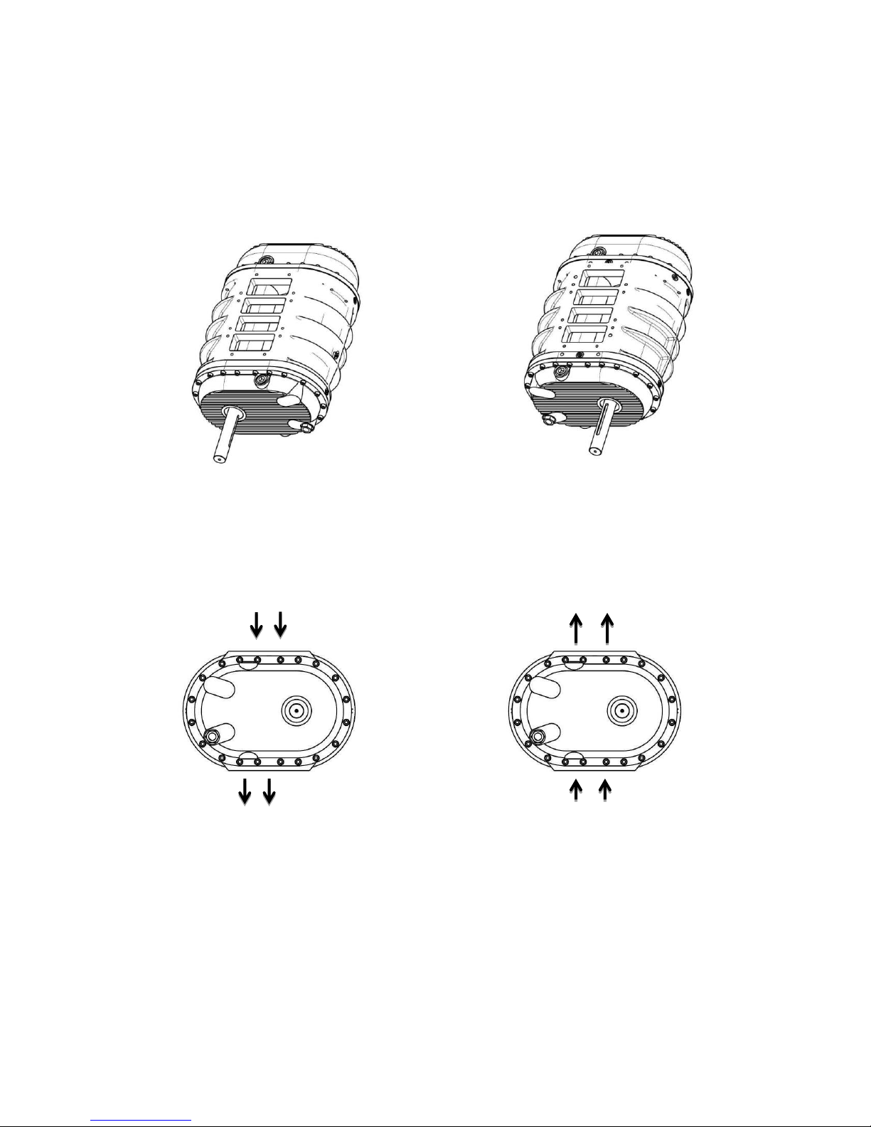
Walinga Chrome Blowers
Right-Hand-Drive Option
The standard shaft position on Walinga Super Chrome Blowers is at the left-hand side when viewed from
the drive end. A right hand drive conversion is available to suit specific applications. Walinga or a trained
dealer must be consulted prior to installation or perform this conversion to ensure that the warranty
coverage is not voided. Note that direction of air-flow through the blower will be the reverse of a standard
blower.
LEFT HAND DRIVE
(STANDARD)
RIGHT HAND DRIVE
(OPTION)
AIR IN
AIR OUT
AIR OUT
AIR IN
Walinga Blowers feature in-house internal chrome hardened
components to increase blower life by up to three times!
Blower Repair & Maintenance Manual #34-05198-6 v1.2 11.2014
7
SPECIAL FEATURES OF WALINGA BLOWERS
Fig. 1
Fig. 3
Fig. 2
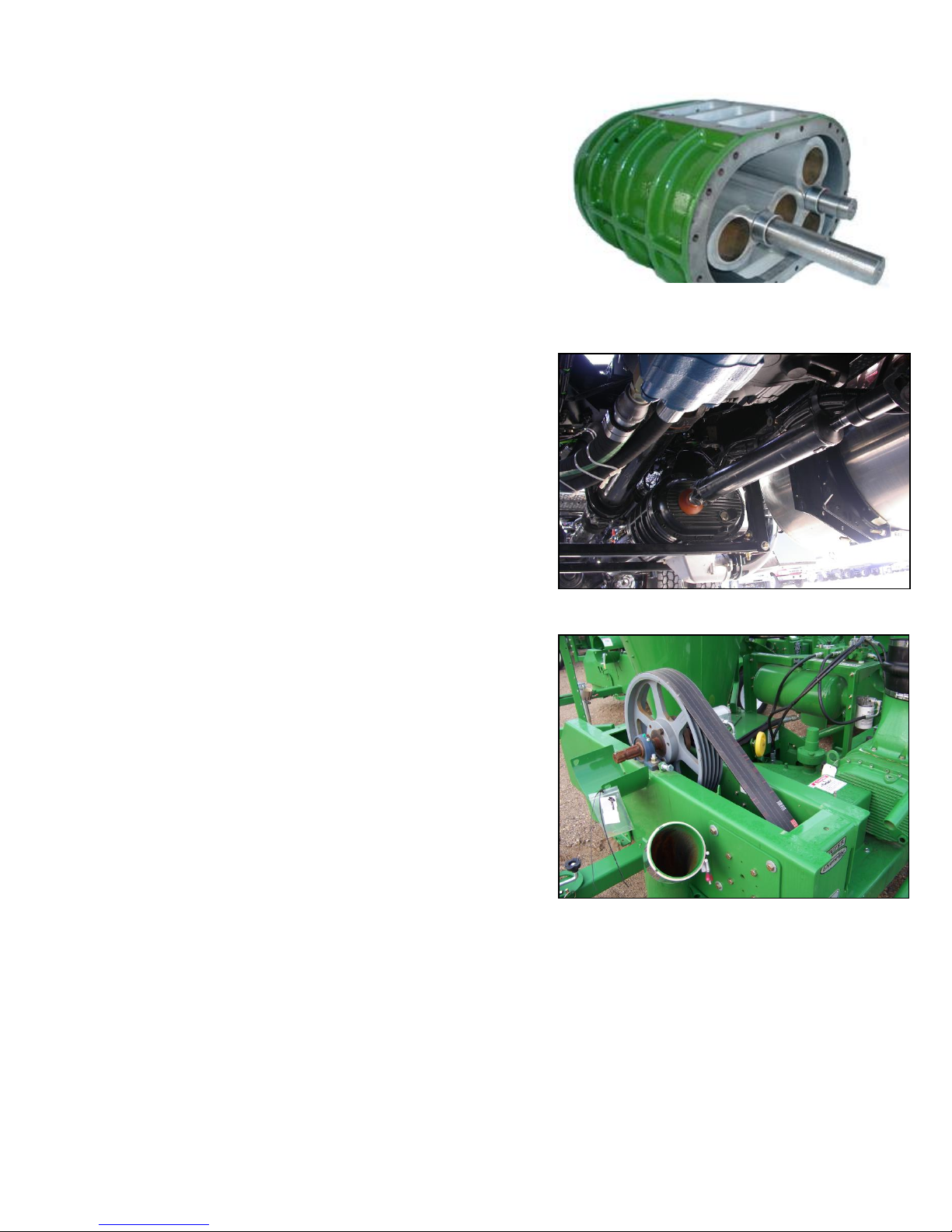
OPERATION
Refer to Figure 1. Rotary positive displacement design
incorporates the use of two figure eight impellers which
rotate in opposite directions to deliver a metered volume
of air. The impellers are separated by minute clearances
which are designed into the unit. These clearances are
maintained by timing gears.
CONSTRUCTION
Walinga blowers are ruggedly built for long life. Impellers
are dynamically balanced to operate without vibration.
Large alloy steel shafts are ground and polished.
Bearings are heavy duty anti-friction type which enable
the blower to maintain its original factory clearances.
Bearings are protected from dirt and contamination by oil
seals. Precision, steel, helical gears are oil lubricated by
a completely self-contained splash system which
atomizes the oil. Breathers are provided to prevent the
air from being contaminated by the blower lubricant.
TYPES OF DRIVE
Direct: Locked bearings on both impeller shafts enable
the blowers to be direct connected. The entire line is
also available with flange adaptors and couplings for
direct connection to internal combustion engines as used
on WALINGA Trailers and Transfer Units. (See Figure
2). In addition, WALINGA blowers are available as
power take off (PTO) units with gear heads in a selection
of ratios to approximately 2.25:1.
V-belt: Walinga blowers can be V-belt driven to permit
changes of speed to accommodate variations in
operation requirements. (See Figure 3)
Blower Repair & Maintenance Manual #34-05198-6 v1.2 11.2014
8
SPECIAL FEATURES OF WALINGA BLOWERS - CONT’D
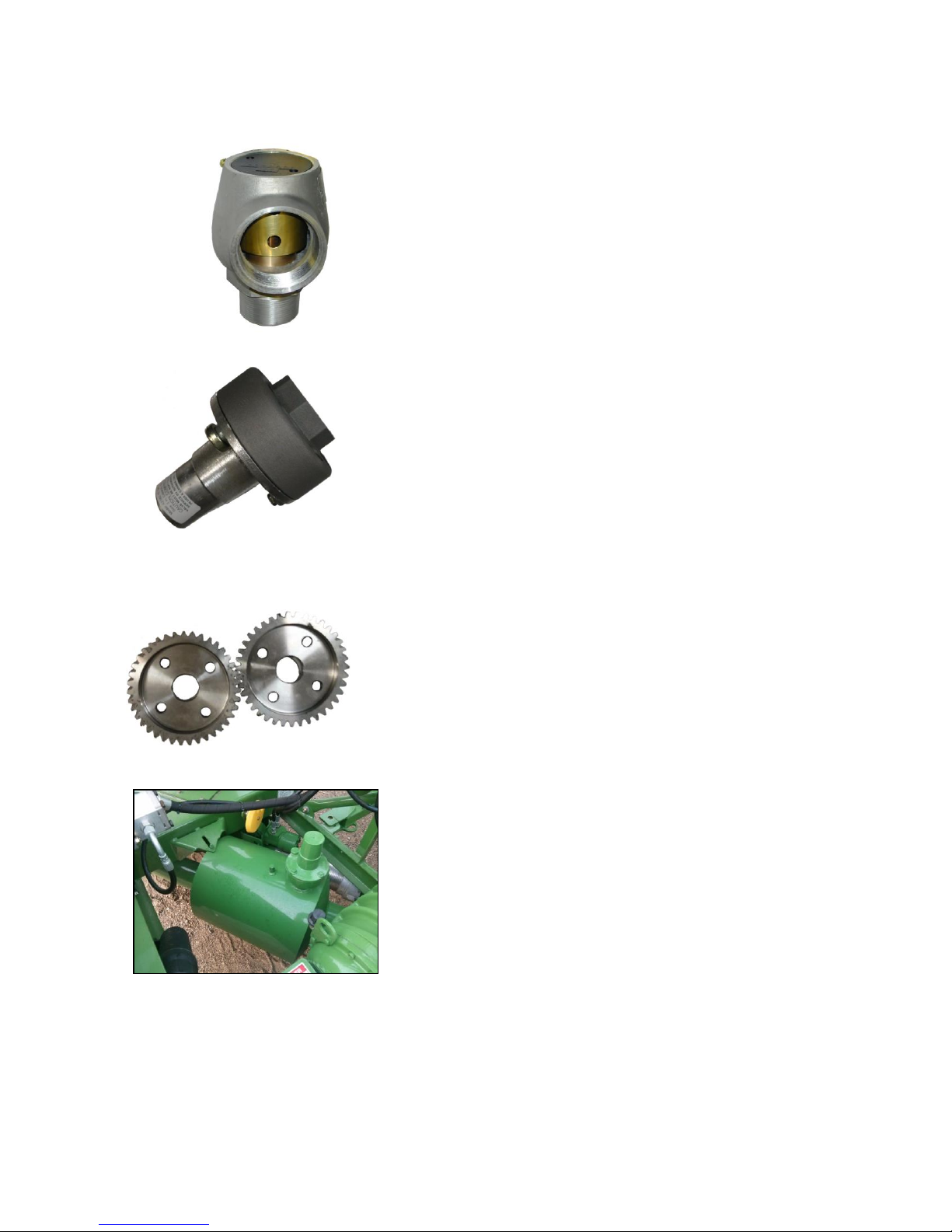
Fig. 4
RELIEF VALVES
VACUUM RELIEF VALVE, spring loaded type.
Built in 1-1/2”, 3”, 4”, and 6” sizes (Figure 4).
Fig. 5
PRESSURE RELIEF VALVE, spring loaded type (Figure 5).
Both valves are supplied as standard equipment.
Fig. 6
TIMING GEARS
Walinga units are fitted with precision steel helical gears and the
exclusive WALINGA TIMING HUB which enables the user to
easily retime the unit in the field and has great shock absorbing
qualities (Figure 6).
Fig. 7
MUFFLER
To minimize sound level with little pressure drop, space and
weight saving packaged-type mufflers are supplied
(Figure 7).
Blower Repair & Maintenance Manual #34-05198-6 v1.2 11.2014
9
SECTION ONE:
BLOWER MODEL #
FRONT
REAR
510
1.14 (1.20)
1.40 (1.50)
614
1.40 (1.50)
2.50 (2.60)
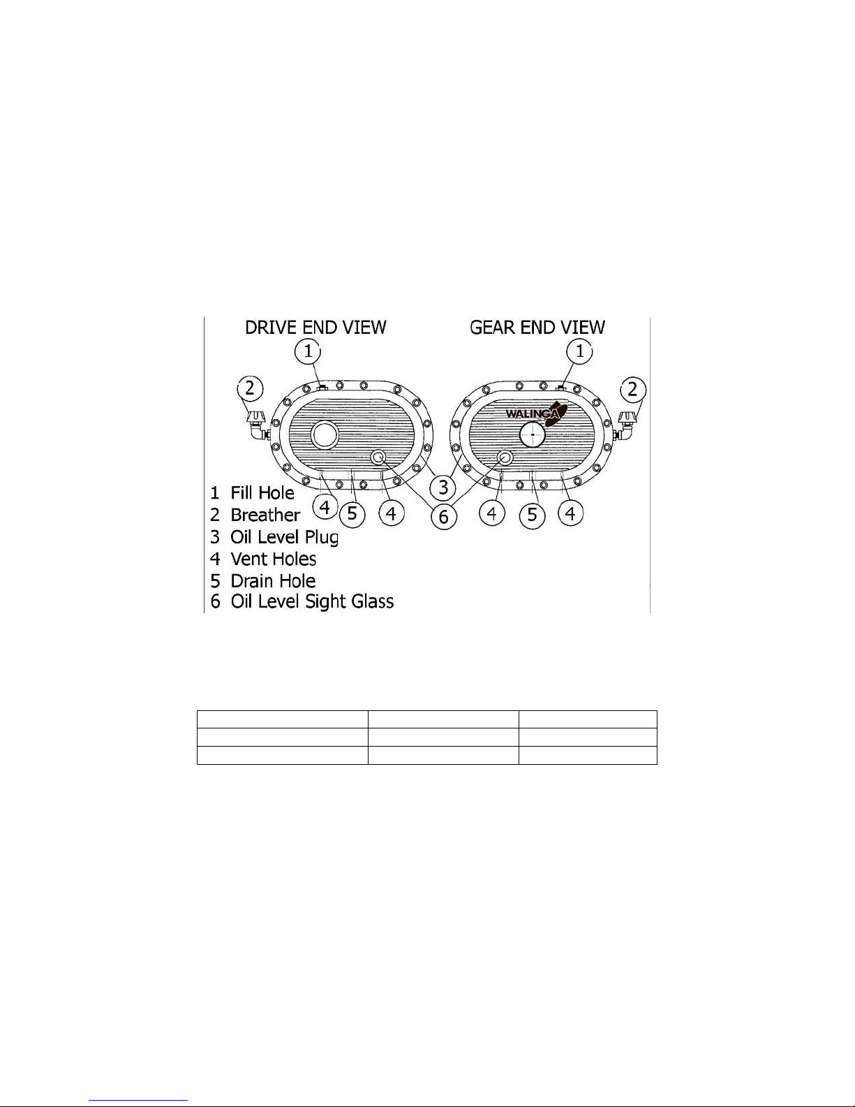
LUBRICATION
Anti-friction bearings and precision, steel helical gears are oil lubricated by a completely self-contained splash
system which atomizes the oil. No external oil feed systems or coolers are required.
Units are shipped with oil in the gear case or bearing housing. Do not operate before checking lubrication. The
vent and oil level plug arrangement are shown in figure 8. Remove the oil fill plug from the fill hole at the top of the
cover and the plug from the oil level hole located at the side of the headplate. Fill the housings until oil drips out of
the oil level hole. Do not overfill. * Replace both plugs. Use Walinga Super Duty Blower Oil (Walinga Part# 98-
13813-5) In most cases, operating temperature of the blower will be in the 100-250 Deg. F. range. Normally the
gear case should be drained, flushed, and refilled every 100 hours or annually. If inspection indicated it is
necessary, do at shorter intervals. The oil level should be checked daily.
Fig.8 Blower Schematics
* On units equipped with sight glass, check to be sure that oil levels registers a quarter of the sight glass.
Table 1
OIL CAPACITY LITERS (US QUARTS)
SPECIAL NOTE: As a result of blower operating temperatures, condensation can occur and result in water formation
in the lubricating oil reservoir. It is important that any water accumulation be eliminated, in order to ensure proper
lubrication and long life.
Allow blower to cool down before driving away to prevent condensation and freeze up in cold weather.
Blower Repair & Maintenance Manual #34-05198-6 v1.2 11.2014
 Loading...