

Wali MF002LM Installation Manual
INSTALLATION MANUAL
Dual Monitor Desk Mount
MF002LM
Supplied Parts List
www.walielectric.com
support@walielectric.com
1-844-SATTLER (18447288537)
RATED
(8kg/17.6lbs)x2
75x75\100x100
MAX 27”
!
WARNING
If you do not understand these directions, or if you have any doubts about the safety of the installation, please call a
qualified technician. Check carefully to make sure there are no missing or defective parts. Improper installation may
cause damage or serious injury. Do not use this product for any purpose that is not explicitly specified in this manual.
Do not exceed weight capacity. We cannot be liable for damage or injury caused by improper mounting, incorrect
assembly or inappropriate use.
TIPOVER WARNING
!
SERIOUS OR FATAL CRUSHING INJURIES CAN OCCUR FROM TIPOVER. TO HELP PREVENT TIPOVER:
● NEVER ALLOW CHILDREN TO CLIMB, STAND, HANG, OR PLAY ON ANY PART OF MONITOR OR STAND.
● USE TIPOVER RESTRAINT OR ANCHOR STAND TO WALL.
USE OF TIPOVER RESTRAINTS MAY ONLY REDUCE, BUT NOT ELIMINATE RISK OF TIP OVER.
SMALL PARTS- NOT FOR CHILDREN UNDER 3 YEARS. ADULT SUPERVISION IS REQUIRED.
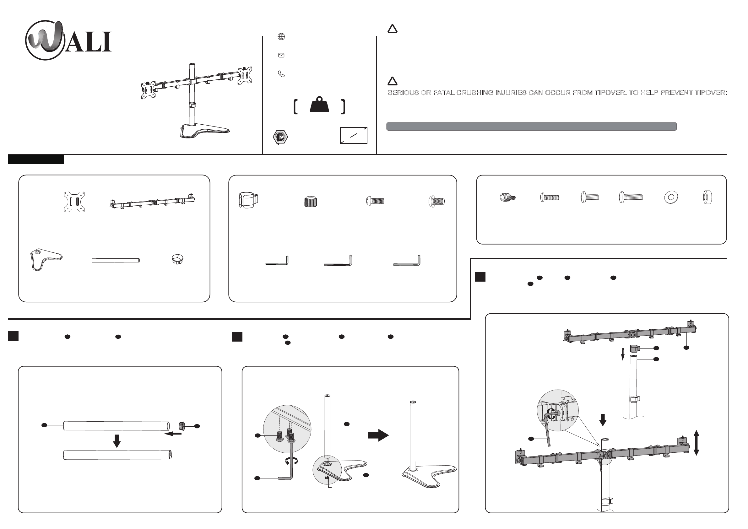
VESA Plate
A (x2)
V-Shape Base
C (x1)
Press Pole Cover E into the top of Pole D . Install the Pole D to the V-Shape Base C using M6x13 Bolts I and tighten with
1
Pole
D (x1)
Arm
B (x1)
Pole Cover
E (x1)
Tool Holder
F (x1)
2
Allen Key 4 mm J .
Allen Key 4mm
J (x1)
Nut
G (x2)
Allen Key 6mm
K (x1)
M3x7 Bolt
H (x2)
Allen Key 5mm
L (x1)
M6x13 Bolt
I (x3)
M4x12 Bolt
M-A (x8)
Put the Tool Holder F and Arm B through the Pole D , adjust the preferred height and tighten using
3
Allen Key 6mm K .
M4x16 Bolt
M-B (x8)
M5x12 Bolt
M-C (x8)
M5x16 Bolt
M-D (x8)
D5 Washer
M-E (x8)
F
D
Spacer
M-F (x8)
B
D
E
I
J
D
K
C

Put the assembled TV/Monitor onto the Arm B and ensure stability. Tighten the VESA plate using Nut G and M3x7 Bolt H with a screwdriver. (Screwdriver not included)
Hand thread screws
into the threaded
inserts on the back of
your TV to determine
which screw diameter
(M4x12 or M5x12) to use.
M4x12
M5x12
Hand thread screws
into the threaded
inserts on the back of
your TV to determine
which screw diameter
(M4x12 or M5x12) to use.
4
Step 4.1
M4x12
Select TV Screws
M5x12
Step 4.2
Select Spacers ( if needed )
5 6
B
Adjust the tilt angle using Allen Key 6mm K .
H
G
K
Step 4.3a
Flat Back Monitor
Select M4x12 Bolt M-A or M5x12 Bolt M-C according to your TV/Monitor, connect
VESA Plate A together with D5 Washer M-E into the mounting holes on the back of
TV/Monitor, tighten with a screwdriver. (Screwdriver not included)
M-E
M-A
M-E
M-C
Guide the cable through the Tool Holder F and wire clips.
F
A
For safety, please do not extend the arms too far forward or backward. This may cause
9
instability and tip over.
10
Store the Allen Keys in the Tool Holder F .
87
K
J
F
Manually swivel, tilt, and rotate the monitor for the best viewing angle. Adjust the height of VESA
Plate A using Allen Key 6mm K .
Step 4.3b
Curved Back Monitor
Select M4x16 Bolt M-B or M5x16 Bolt M-D according to your TV/Monitor, connect
VESA Plate A together with D5 Washer M-E and Spacer M-F into the mounting
holes on the back of TV/Monitor, tighten with a screwdriver. (Screwdriver not included)
M-E
M-F
M-B
M-D
A
K
A
Note: Please make sure two arms are aligned and balanced.
0.8” Height Adjustment
 Loading...