

Wali M001LM Installation Manual
INSTALLATION MANUAL
Single Monitor Desk Mount
M001LM
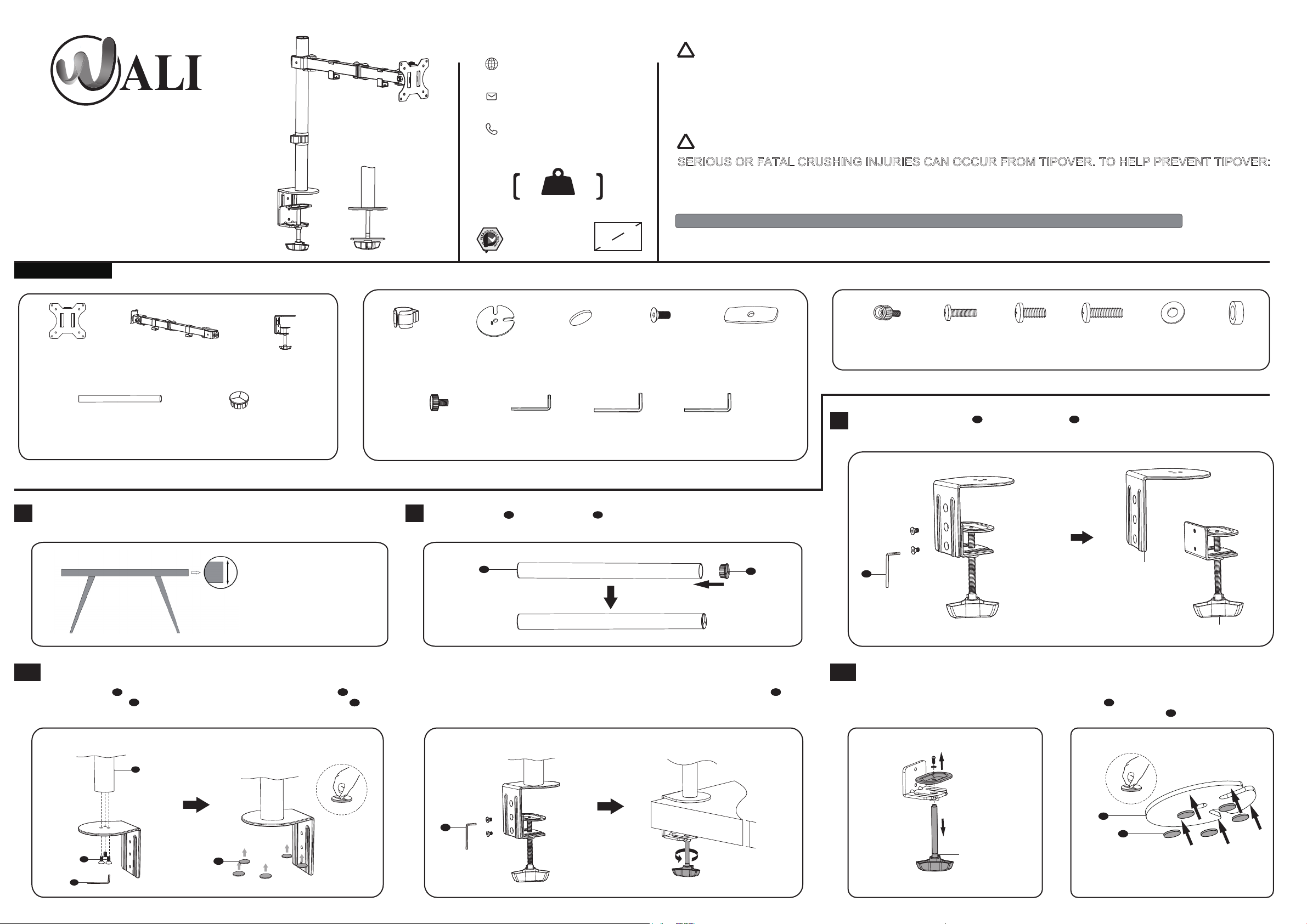
Supplied Parts List
www.walielectric.com
support@walielectric.com
1-844-SATTLER (18447288537)
RATED
8kg/17.6lbs
75x75\100x100
MAX 32”
!
WARNING
If you do not understand these directions, or if you have any doubts about the safety of the installation, please call a
qualified technician. Check carefully to make sure there are no missing or defective parts. Improper installation may
cause damage or serious injury. Do not use this product for any purpose that is not explicitly specified in this manual.
Do not exceed weight capacity. We cannot be liable for damage or injury caused by improper mounting, incorrect
assembly or inappropriate use.
TIPOVER WARNING
!
SERIOUS OR FATAL CRUSHING INJURIES CAN OCCUR FROM TIPOVER. TO HELP PREVENT TIPOVER:
● NEVER ALLOW CHILDREN TO CLIMB, STAND, HANG, OR PLAY ON ANY PART OF MONITOR OR STAND.
● USE TIPOVER RESTRAINT OR ANCHOR STAND TO WALL.
USE OF TIPOVER RESTRAINTS MAY ONLY REDUCE, BUT NOT ELIMINATE RISK OF TIP OVER.
SMALL PARTS- NOT FOR CHILDREN UNDER 3 YEARS. ADULT SUPERVISION IS REQUIRED.
VESA Plate
A (x1)
Pole
D (x1)
Measure the thickness of your mounting surface or desk
1 2
Arm
B (x1)
C-Clamp
C (x1)
Pole Cover
E (x1)
Tool Holder
F (x1)
Fit clamp: 0.39”- 3.3”
Grommet: 0.39”- 3”
Grommet Base Plate
G (x1)
Top Screw
K (x1)
Press Pole Cover E into the top of Pole D .
Allen Key 4mm
L (x1)
D
Anti-skid Pad
H (x5)
Allen Key 6mm
M (x1)
M6x12 Bolt
I (x3)
Support Plate
Allen Key 5mm
N (x1)
J (x1)
E
M4x12 Bolt
M-A (x4)
Loosen the bolts on C-Clamp C using Allen Key 4mm L .
3
L
M4x16 Bolt
M-B (x4)
M5x12 Bolt
M-C (x4)
M5x16 Bolt
M-D (x4)
D5 Washer
M-E (x4)
C-Clamp Brace
Spacer
M-F (x4)
Clamp
4A 4B
Option A : Clamp Installation Option B: Grommet Base Installation
1.Connect Pole D and C-Clamp Brace from the bottom using M6x12 Bolt I and tighten
with Allen Key 4mm L .Tear off the protect paper and attach Anti-Skid Pads H to the
bottom designated position of C-Clamp Brace as image shown.
D
2. Connect C-Clamp to C-Clamp Brace using the bolts and tighten with Allen Key 4mm L .
Rotate the hand knob clockwise to fasten for stability.
L
1. Loosen the screw to release the hand
knob using a screwdriver as image shown.
(Screwdriver not included)
0.39”-3.3”
I
L
H
2. Tear off the protect paper and attach Anti-Skid
Pads H to the bottom designated position of
Grommet Base Plate G as image shown.
G
H
Hand knob
3a.Existing Grommet Hole Installation 3b.Self-drilled Grommet Hole Installation
If the existing grommet hole comes with a plastic protector, remove it to ensure a flat surface
before installing the desk mount. Place the Grommet Base Plate G and Pole D to the
grommet hole. Insert the hand knob through the center hole of Support Plate J and desk hole,
rotate the hand knob clockwise to fasten for stability.
D
Mark the position of the hole on your mounting surface. Drill a 3/8"(10mm) diameter hole at
the marked position through the mounting surface. Place the Grommet Base Plate G and
Pole D to the grommet hole. Insert the hand knob through the center hole of Support Plate
J and desk hole, rotate the hand knob clockwise to fasten for stability.
D
ø 10mm
(ø ") 3/8
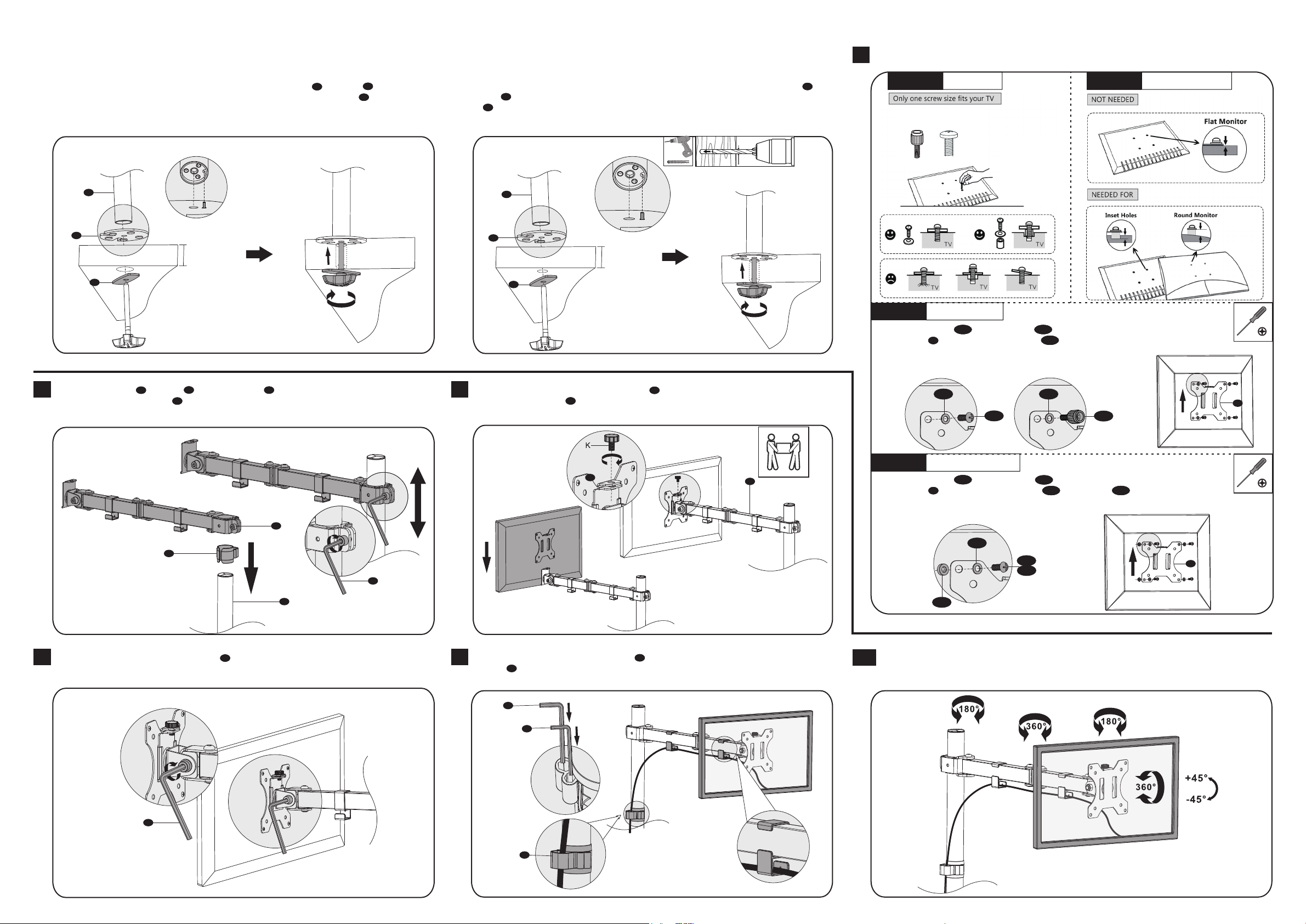
5
Step 5.1
M4x12
Select TV Screws
M5x12
Hand thread screws
into the threaded
inserts on the back of
your TV to determine
which screw diameter
(M4x12 or M5x12) to use.
Step 5.2
Select Spacers ( if needed )
G
0.39”-3”
J
Put the Tool Holder F and Arm B through the Pole D , adjust the preferred height and
6
tighten using Allen Key 6mm M .
B
F
G
0.39”-3”
J
Step 5.3a
Flat Back Monitor
Select M4x12 Bolt M-A or M5x12 Bolt M-C according to your TV/Monitor, connect
VESA Plate A together with D5 Washer M-E into the mounting holes on the back of
TV/Monitor, tighten with a screwdriver. (Screwdriver not included)
Put the assembled TV/Monitor onto the Arm B and ensure stability, tighten the VESA
7
plate using Top Screw K .
Step 5.3b
K
B
Select M4x16 Bolt M-B or M5x16 Bolt M-D according to your TV/Monitor, connect
M-E M-E
M-C
Curved Back Monitor
A
M-A
VESA Plate A together with D5 Washer M-E and Spacer M-F into the mounting
holes on the back of TV/Monitor, tighten with a screwdriver. (Screwdriver not included)
M-E
M-B
M-D
M
A
Adjust the tilt angle using Allen Key 6mm M .
8
M
D
Guide the cable through the Tool Holder F and wire clips. Store the Allen Keys in the Tool
9
Holder F .
M
L
F
Manually swivel, tilt, and rotate the monitor for the best viewing angle.
10
M-F
 Loading...