

Waldorf Music MiniWorks, 4-Pole User's Manual
4
pole
mini
WORKS
User’s Manual

EG-Konformitätserklärung
Declaration of Conformity
Für das folgend bezeichnete Erzeugnis
For the following named product
Waldorf 4-pole
Serien-Nr. /
wird hiermit bestätigt, daß es den Schutzanforderungen entspricht, die in der
Richtlinie 89/336/FWG des Rates zur Angleichung der Rechtsvorschriften der
Mitgliedstaaten über die elektromagnetische Verträglichkeit festgelegt sind;
außerdem entspricht es den Vorschriften des Gesetzes über die
elektromagnetische Verträglichkeit von Geräten (EMVG) vom 30. August 1995.
will be hereby declared that it conforms to the requirements of the Council
Directive 89/336/FWG for radio frequency interference. It also complies with
the regulations about radio interference of electronic devices dated on August
30th, 1995.
Zur Beurteilung des Erzeugnisses hinsichtlich der elektromagnetischen
Verträglichkeit wurden folgende einschlägige harmonisierte Normen
herangezogen:
The following standards have been used to declare conformity:
- DIN EN 55013:08-1991, DIN EN 50081-1:03-1993, DIN EN
55020:05-1995,
DIN EN 50082-1:03-1993
Diese Erklärung wird verantwortlich für den Hersteller abgegeben:
T
his declaration is given responsible for the manufacturer:
Waldorf Electronics GmbH
Neustraße 12
D-53498 Waldorf
Serial No.
95500395 - 96521500
Waldorf, 01.12.95
Wolfgang Düren, Geschäftsführer
Wolfgang Düren, Managing Director

Waldorf Electronics assumes no responsibility for any errors which may appear in
this manual. The content of this manual is for informational purposes and is
subject to change without notice. Considerable effort has been made to ensure
that this manual is free of inaccuracies and omissions. Waldorf Electronics makes
no warranty of any kind including but not limited to any implied warranties of
merchantability and fitness for particular purpose with regard of this manual.
No Part of this manual may be copied without the express written permission of
Waldorf Electronics, Neustraße 12, D 53 498 Germany
Software Development
Stefan Stenzel
Hardware Development
Thomas Kircher
Design
Axel Hartmann
Special Thanks to :
Andreas Busse, Phillip Dahlhausen, Wolfram Franke, Jens Hoffmann, Joachim Lenz,
the Maier brothers, Erna Moormann, Georg Müller, Martin Neideck, Oliver
Rockstedt, Frank Schneider, Erik Wiegand and all people at TSI, esp. Lu.
© Waldorf Electronics 1995
E4

Table of Contents
1. Introduction... E 6
1.1 Conventions and Terminology.. E 6
2. Applications.. E 7
2.1 The 4-Pole and Electric Guitars... E 7
2.2 The 4-Pole and Electronic Drumpads... E 8
2.3 The 4-Pole and Synthesizers/Samplers... E 9
2.4 The 4-Pole as a Denoiser... E 9
2.5 The 4-Pole as an Effects Device... E 10
3. Control Features... E 11
4. Operating the 4-Pole... E 12
4.1 Cable Connections and Powering Up... E 12
4.2 Selecting Programs... E 12
4.3 Selecting an Edit level... E 12
4.4 Editing Parameters... E 13
4.5 Knob Mode... E 13
4.6 Viewing Parameters... E 14
4.7 The Compare Function... E 14
4.8 The Store Function... E 15
5. The Parameters... E 15
5.1 Edit Level 1, VCF Envelope... E 15
5.2 Edit Level 2, VCA Envelope... E 16
5.3 Edit Level 3... E 16
5.4 Edit Level 4, Modulations... E 18
5.5 Edit Level 5... E 19
5.6 Edit Level 6... E 19
6. Modulation Sources... E 23
7. MIDI Control... E 24
7.1 Program Change... E 24
7.2 Note On/Off... E 24
7.3 Controller... E 25
7.4 Pitch Bend, Aftertouch... E 25
7.5 Sending System Exclusive Data... E 25
7.6 Receiving System Exclusive Data... E 26
8. System Exclusive Data Format... E 27
8.1 Program Dump... E 27
8.2 Program Bulk Dump... E 28
8.3 All Dump... E 29
8.4 Program Dump Request... E 31
8.5 Program Bulk Dump Request... E 32
8.6 All Dump Request... E 32
9. Controller Number... E 33
10. Glossary... E 34
11. MIDI Implementation Chart... E 39
E5

1. Introduction
Thank you for purchasing the Waldorf miniworks 4-pole filter! This
device lets you filter any type of signal via a 24dB lowpass filter
featuring resonance. This filter is identical to the one the
MicroWave is equipped with. In addition to the filter frequency
and resonance, you can manipulate volume and position within
the stereo signal via complex modulations. A comprehensive MIDI
implementation provides comfortable handling via your keyboard
and sequencer.
1.1 Conventions and Terminology
For the sake of simplicity, all technical terms in this manual
correspond to the parameter names we used for the 4-Pole. You
will find a glossary in the final chapter of this manual; it includes a
brief definition of all pertinent terms.
E6
2. Applications
Because its trigger-function can be activated manually, via MIDI, a
separate trigger-signal, and the actual audio-signal, the 4-Pole is
suitable for a wid range of applications. The following sections
illustrate a few typical applications. You of course can select any
other desired configuration; just let your imagitnations be your
guide.
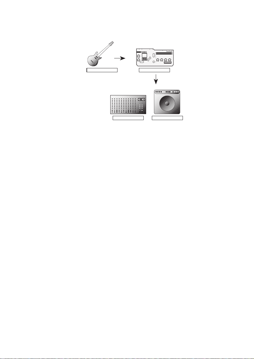
2.1 The 4-Pole and Electric Guitars
If your rig includes several effects processors, patch in the 4-Pole
between your distortion unit and reverb or delay unit in the signal
chain.
Drumpad
Out
Trigger
In
4
Guitar
Audio
Out
Audio
In
pole
VCF
VCA
MIDI
Out
MIDI
In
4-Pole
Synthesizer
Expander / Sampler
Audio
Out
Line
Line
In
Mixer Amp
In
Use the envelope signal to control the cutoff frequency at a
medium resonance to generate an automatic wah-wah effect. As
an alternative to the signal envelope, you can of course use the
LFO.
The factory programs 21 to 24 were programmed specifically for
electric guitars.
E7
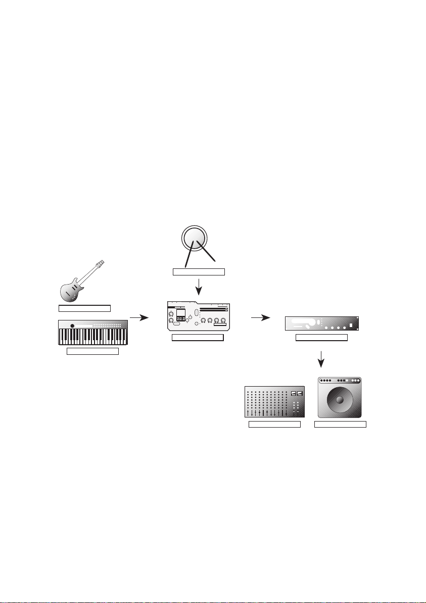
2.2 The 4-Pole and Electronic Drumpads
You may use an electronic drumpad to trigger the 4-Pole’s
envelopes. Connect the pad’s output to the <Trigger In> jack and
adjust the signal level via the <Trigger Level> control.
Drumpad
Out
Trigger
In
4
Guitar
Audio
Out
Audio
In
pole
VCF
VCA
MIDI
Out
MIDI
In
4-Pole
Synthesizer
Expander / Sampler
Audio
Out
Line
Line
In
Mixer Amp
In
You can trigger any signal you have patched into the <Audio In>
jack. You can also connect a MIDI sound generator to the <MIDI
Out> jack and play its sounds via your drumpad. You will probably
have to assign the MIDI channel and the note number (Section
5.6).
Program 25 was programmed specifically for use with drumpads;
for this program, the signal envelope is used to control the cutoff
frequency. The filter resonance is tuned so that the filter oscillates
and produces a sound much like the early drum synthesizers.
E8
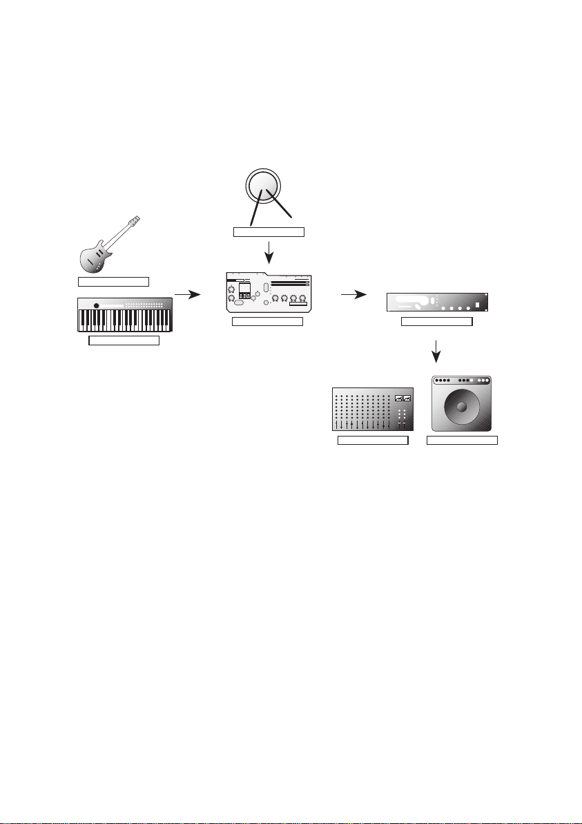
2.3 The 4-Pole and Synthesizers/Samplers
Connect the synthesizer’s MIDI output to the <MIDI In> jack and
the Audio output to the 4-Pole’s <Audio In> jack.
MIDI
Synthesizer
Out
Audio
Out
Audio
Line
Mixer Amp
MIDI
In
4
pole
In
4-Pole
Audio
Out
In
Line
VCF
VCA
In
The envelopes can be triggered via the MIDI notes that you or the
device are play. The filter can be modulated via envelopes, the
LFO, etc. in the same manner as with an analog synthesizer, which
is an especially interesting feature when you are using samplers
and sound generators that are not equipped with analog filters.
2.4 The 4-Pole as a Denoiser
4
Guitar
Audio
Out
Audio
In
Line
In
pole
Audio
Out
4-Pole
Line
VCF
VCA
In
Mixer Amp
Let the appropriate envelopes control the volume and cutoff
frequency. Use the envelopes for a short attack and a relatively
long release time and set the Audio Trigger to Single Trigger
Mode (refer to Section 5.6). As an alternative, you can also use the
signal envelope to control the cutoff frequency. Program 26 is an
example of a noise suppression program.
E9
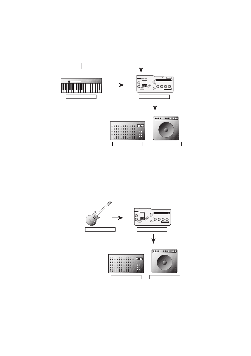
2.5 The 4-Pole as an Effects Device
Audio
Out
Audio
In
4
pole
VCF
VCA
Guitar
Line
In
Mixer Amp
Audio
Out
4-Pole
Line
In
The LFO is capable of producing frequencies in the audio range.
Its highest frequency is 261.6 Hz, which is equivalent to a C note.
If you modulate the cutoff frequency or volume via one of these
LFOs, you will generate an ringmodulation like effect. For an
example, check out Program 28.
You can also achieve audible effects by panning (refer to Section
5.4 PAN MOD) via an LFO or envelope. You can generate
everything from a slow right/left wavering effect to a stereo
amplitude modulation. For an example, check out Program 29.
You can also generate compression when the signal envelope,
preceded by a minus sign, modulates the volume. Check out
Program 30.
Undoubtedly you have already realized that with the Waldorf and
just a little imagination, you can create an untold number of other
effects or effect combinations based on these examples.
E10
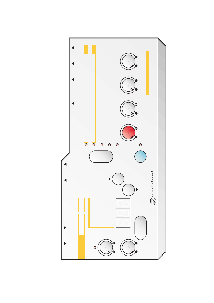
3. Control Features
ThruIn OutAC 9V
MIDI
VCF
Attack Decay Sustain Release
VCA
Attack Decay Sustain Release
Speed Mod / Src
VCF Env Cutoff VCA Env Volume LFO Speed / Shape
Cutoff Mod / Src Reso Mod / Src Volume Mod / Src Pan Mod / Src
Cutoff Resonance Volume Panning
Device ID
GLOBAL PARAMETERS
MIDI Note
Gate Time Source / Trigger MIDI Control MIDI Channel Trigger
Mode
Dump
Out
Compare
Shift
Store
pole
4
8 Vel • VCA Env
9 Velocity
10 Keytrack
11 Pitchbend
12 Modwheel
13 Aftertouch
14 Breath Ctr
15 Foot Ctr
0 off
1 LFO
2 LFO • ModW.
3 LFO • Aftertouch
4 LFO • VCA Env
5 VCF Env
6 VCA Env
E11
7 Signal Env
Gain
Manual Trigger
Level
MODULATION SOURCES
WORKS
Audio In Trigger In L R
mini

4. Operating the 4-Pole
4.1 Cable Connections and Powering Up
The 4-Pole’s <Audio In> is a monophonic circuit whereas the
outputs (<Out L> and <Out R>) constitute a stereophonic circuit.
In order to exploit the 4-Pole’s potential to the fullest we
recommend you connect it in stereo mode. All audio in/outputs
and the trigger input were implemented as 1/4” jacks.
Connect the <Audio In> jack to your signal source’s output and
<Out L> and <Out R> to an amp/mixing console’s input. If you
want to use a 1/4” stereo plug to access the 4-Pole’s output
signal, you must insert it into the <Out L> jack. The mono master
signal is routed to the <Out R> jack, assuming you have not
plugged a cable into the <Out L> plug.
Connect the included powerpack to the 9V socket located on the
rear panel of the device. Then plug the powerpack into a wall
socket. Your 4-Pole is now ready to roll.
4.1 Selecting Programs
Use the <Up> and <Down> keys to select programs. The display
indicates the program you have selected. Programs 1-20 are
freely programmable whereas programs 21-40 feature non-user
programmable fixed factory programs.
When you initially switch on the 4-Pole the first 20 programs are
identical to the other twenty factory programs.
4.3 Selecting an Edit level
Select any of the six different edit levels via the <Mode> key. The
diverse levels are indicated by the Mode LEDs.
You can also press and hold the <Mode> key and then select an
edit level via the <Up/Down> key. At the 6th level, the first five
Mode LEDs function as a display for the signal envelope (refer to
Chapter 6).
When you select a level, the current program number is
displayed, and is usually preceded by the letter “P”. The letter “E”
indicates that this program was edited. “C” indicates the program
is in Compare mode (refer to Section 4.7).
E12

4.4 Editing Parameters
Select an edit level (e.g. Level 1, VCF Envelope) and manipulate the
corresponding control located in the column of the desired
mode, e.g. <Attack>. The display will immediately indicate the
edited attack value. In several modes, another parameter is
selected when you press the <Shift> key, e.g. LFO Shape. These
are indicated on the control panel via orange markings.
If you change a parameter, the current program is automaticallly
in edit mode, indicated by the letter “E” preceding the program
number. However, the 4-Pole is equipped with just one editing
buffer, so that all changes you have made to a program are
irretrievably lost if you did not save them first (refer to Section
4.8)! These controls have several different functions, as the
following chapter will illustrate.
4.5 Knob Mode
The 4-Pole was equipped with potentiometers featuring right and
left limits because we feel these are the best tools for editing
parameters. They do have a disadvantage: the position of the
knob rarely corresponds to the actual value of a given program’s
parameter. Consequently, we integrated two distinct modes to
give you the opportunity to edit values as you see fit.
If you press and hold the <Mode> key and simultaneously press
the <Manual Trigger> key, “KNOB MODE” will appear in the display.
Knob Mode can be changed again by pressing the <Mode> and
<Manual Trigger> keys again.
JMP - Jump Mode
In Jump Mode, the parameter jumps directly to the value you set
via the knob regardless of the parameter’s original value.
E13
 Loading...