

Page 1
Bedienungsanleitung
User's Manual
Page 2

Page 3
➤
Vielen Dank für den Kauf dieses Waldorf Produktes. Es zeichnet sich durch
Zuverlässigkeit und Langlebigkeit aus. Dennoch können Material- oder
Verarbeitungsfehler nicht völlig ausgeschlossen werden. Daher bieten wir
Ihnen eine verlängerte Garantie. Damit Garantieleistungen in Kraft treten,
müssen Kaufrechnung und Garantiekarte vollständig ausgefüllt innerhalb
von 14 Tagen zurückgesandt werden. Diese Garantie erstreckt sich auf alle
Defekte in Material und Verarbeitung für den Zeitraum von 1 Jahr ab Kauf
des Produktes. Während der Garantiezeit ersetzt oder repariert Waldorf
Electronics das durch Waldorf Electronics oder ein autorisiertes Service
Zentrum als defekt befundene Produkt, ohne dem Kunden Material- oder
Arbeitsaufwand in Rechnung zu stellen.
Um die Garantie in Anspruch zu nehmen, muß sich der Kunde zunächst
telefonisch mit dem zuständigen Vertrieb in Verbindung setzen. Produkte,
die ohne vorherige Absprache eingesandt werden, können nicht kostenfrei
ausgetauscht bzw. repariert werden.
Das Produkt muß frei und versichert in Originalverpackung eingesandt
werden. Detaillierte Fehlerbeschreibungen sind beizufügen. Unfrei und/oder
nicht originalverpackt eingesandte Produkte gehen ungeöffnet zurück.
Waldorf Electronics behält sich vor, das eingesandte Produkt auf den neusten
Stand der Technik zu bringen, wenn dies erforderlich sein sollte.
Diese Garantie deckt keine Defekte ab, die durch unsachgemäße
Behandlung oder Eingriffe von unautorisierten Personen verursacht wurden
und ist beschränkt auf die Behebung von Defekten, die während der
normalen Nutzung durch Material- oder Verarbeitungsfehler aufgetreten
sind.
Thank you for choosing this Waldorf product. It is a dependable device and
is designed to last. However, the potential for defects in material or
workmanship cannot be eradicated completely. This is why we provide an
extended warranty for you.
To ensure your unit has full warranty coverage, mail the receipt and the fully
completed warranty card back within 14 days of purchase.
This warranty covers all defects in material and workmanship for a period of
one year from the date of original purchase. During this time, Waldorf
Electronics will repair or replace the product without charge for materials or
labor, provided the product was first inspected and found faulty by Waldorf
Electronics or an authorized service center. You must first contact your dealer
or distributor by telephone. Products that were mailed without prior
agreement cannot be exchanged or repaired free of charge.
The unit must be insured and sent prepared in its original package. Please
include a detailed description of the defect. Products that were not send
prepared or in the original package will be returned unopened.
Waldorf Electronics reserves the right to upgrade the unit with the latest
technological advances if necessary.
This warranty does not cover defects due to abuse, operation under other
than specified conditions, or repair by unauthorized persons. The warranty
covers only those malfunctions caused by material or workmanship defects
that occur during normal operation.
Bitte schicken Sie die Garantiekarte vollständig ausgefüllt zusammen mit
einer Kopie der Kaufrechnung zurück, um die Produktgarantie in Anspruch
nehmen zu können.
Please fill out this warranty card completely, include a copy of the purchase
receipt and send the two items to us in order to ensure the warranty is valid.
Garantiekarte / Warranty Card
Produktgarantie / Product Warranty
✁
Produkt / Product:
micro
S Y N T H E S I Z E R
micro
S Y N T H E S I Z E R
micro
Sonderausstattungen / Custom features:
Sonstige verwendete Geräte / Other used equipment:
Seriennummer / Serial number: Kaufdatum / Purchase date:
Name Ihres Händlers / Name of your dealer:
Ort Ihres Händlers / City of your dealer:
➤
➤
➤
Waldorf Electronics
Support Department
Neustraße 9-12
53498 Waldorf
Germany
Straße / Street:
PLZ, Wohnort / ZIP Code, City:
Land / Country:
Telefon / Telephone:
Telefax / Facsimile:
Name / Name:
Page 4

4
Produktunterstützung / Product Support
✁
Wenn Sie Fragen zu Ihrem Waldorf Produkt haben, gibt es vier
Möglichkeiten, uns zu kontaktieren:
If you have any questions about your Waldorf product, feel free to contact us
via one of the four options listed below.
Schicken Sie uns eine E-Mail. Das ist der mit
Abstand effizienteste und schnellste Weg, uns zu
erreichen. Ihre Fragen können sofort an die
richtige Stelle weitergeleitet und innerhalb
kürzester Zeit beantwortet werden.
Senden Sie uns ein Telefax. Fast so schnell wie EMail, allerdings für Sie und uns weniger
komfortabel.
Schicken Sie uns einen Brief. Etwas langsamer,
dafür jedoch genauso zuverlässig wie ein
Telefax.
Und wenn es ganz dringend ist, rufen Sie uns an.
Wir versuchen, Ihre Fragen möglichst sofort zu
beantworten.
Send us an e-mail message. This is the most
efficient and fastest way to contact us. Your
questions will be forwarded immediately to the
resident expert and you will quickly receive an
answer.
Send us a fax. This is as fast as e-mail, but not
quite as comfortable for you and us.
Send us a letter. It will take a bit longer, but it is
just as dependable as a fax.
If you’re in big hurry, call us, we’ll try to answer
your questions right away.
+49-(0)2636-976499
+49-(0)2636-976464
Waldorf Electronics
Neustraße 9-12
53498 Waldorf, Germany
4
3
3
2
2
1
1
Page 5

Contents
Control Features and Connections of the MicroWave II . . . . . . . . . . . . . . . . . . . . . . . 7
Additional Controls and Connectors of the MicroWave XT . . . . . . . . . . . . . . . . . . . . . 8
Additional Controls and Connectors of the XTk . . . . . . . . . . . . . . . . . . . . . . . . . . . . . 9
Foreword . . . . . . . . . . . . . . . . . . . . . . . . . . . . . . . . . . . . . . . . . . . . . . . . . . . . . . . . 10
About this Manual . . . . . . . . . . . . . . . . . . . . . . . . . . . . . . . . . . . . . . . . . . . . . . . . . 11
Symbols . . . . . . . . . . . . . . . . . . . . . . . . . . . . . . . . . . . . . . . . . . . . . . . . . . . . . 11
Highlighted Control Features and Parameters . . . . . . . . . . . . . . . . . . . . . . . . . . 11
General Safety Guidelines . . . . . . . . . . . . . . . . . . . . . . . . . . . . . . . . . . . . . . . . . . . . 12
Setup and Operation . . . . . . . . . . . . . . . . . . . . . . . . . . . . . . . . . . . . . . . . . . . . . . . . 14
Inventory . . . . . . . . . . . . . . . . . . . . . . . . . . . . . . . . . . . . . . . . . . . . . . . . . . . . 14
Setup . . . . . . . . . . . . . . . . . . . . . . . . . . . . . . . . . . . . . . . . . . . . . . . . . . . . . . . 14
Connections . . . . . . . . . . . . . . . . . . . . . . . . . . . . . . . . . . . . . . . . . . . . . . . . . . 14
Analog Input . . . . . . . . . . . . . . . . . . . . . . . . . . . . . . . . . . . . . . . . . . . . . . . . . 15
Quick Start . . . . . . . . . . . . . . . . . . . . . . . . . . . . . . . . . . . . . . . . . . . . . . . . . . . . . . . 16
Operation . . . . . . . . . . . . . . . . . . . . . . . . . . . . . . . . . . . . . . . . . . . . . . . . . . . . . . . . 23
Power Switching . . . . . . . . . . . . . . . . . . . . . . . . . . . . . . . . . . . . . . . . . . . . . . . 23
Powering up . . . . . . . . . . . . . . . . . . . . . . . . . . . . . . . . . . . . . . . . . . . . . 23
Switching off . . . . . . . . . . . . . . . . . . . . . . . . . . . . . . . . . . . . . . . . . . . . . 23
Adjusting the Master Volume . . . . . . . . . . . . . . . . . . . . . . . . . . . . . . . . . . . . . . 23
Selecting Programs . . . . . . . . . . . . . . . . . . . . . . . . . . . . . . . . . . . . . . . . . . . . . 23
Selecting Sound and Multi Mode . . . . . . . . . . . . . . . . . . . . . . . . . . . . . . . . . . . 24
Editing Parameters . . . . . . . . . . . . . . . . . . . . . . . . . . . . . . . . . . . . . . . . . . . . . 25
Edit Buffers . . . . . . . . . . . . . . . . . . . . . . . . . . . . . . . . . . . . . . . . . . . . . . . . . . . 27
The Compare Function . . . . . . . . . . . . . . . . . . . . . . . . . . . . . . . . . . . . . . . . . . 27
Recalling Edits . . . . . . . . . . . . . . . . . . . . . . . . . . . . . . . . . . . . . . . . . . . . . . . . 28
Storing Programs . . . . . . . . . . . . . . . . . . . . . . . . . . . . . . . . . . . . . . . . . . . . . . 28
The Play Access Page . . . . . . . . . . . . . . . . . . . . . . . . . . . . . . . . . . . . . . . . . . . 29
Panic Function . . . . . . . . . . . . . . . . . . . . . . . . . . . . . . . . . . . . . . . . . . . . . . . . 30
Randomizing a Program . . . . . . . . . . . . . . . . . . . . . . . . . . . . . . . . . . . . . . . . . 30
Initializing Programs . . . . . . . . . . . . . . . . . . . . . . . . . . . . . . . . . . . . . . . . . . . . 31
Editing Parameters on the MicroWave XT . . . . . . . . . . . . . . . . . . . . . . . . . . . . . 31
Switching the Octave Setting on the XTk . . . . . . . . . . . . . . . . . . . . . . . . . . . . . 32
About Wavetable Synthesis . . . . . . . . . . . . . . . . . . . . . . . . . . . . . . . . . . . . . . . . . . . 33
Sound Parameters . . . . . . . . . . . . . . . . . . . . . . . . . . . . . . . . . . . . . . . . . . . . . . . . . . 38
Overview of Functions . . . . . . . . . . . . . . . . . . . . . . . . . . . . . . . . . . . . . . . . . . 38
Oscillators . . . . . . . . . . . . . . . . . . . . . . . . . . . . . . . . . . . . . . . . . . . . . . . . . . . 39
Oscillator 1 . . . . . . . . . . . . . . . . . . . . . . . . . . . . . . . . . . . . . . . . . . . . . . 39
Oscillator 2 . . . . . . . . . . . . . . . . . . . . . . . . . . . . . . . . . . . . . . . . . . . . . . 40
Waves . . . . . . . . . . . . . . . . . . . . . . . . . . . . . . . . . . . . . . . . . . . . . . . . . . . . . . 43
Wave 1 . . . . . . . . . . . . . . . . . . . . . . . . . . . . . . . . . . . . . . . . . . . . . . . . . 43
Wave 2 . . . . . . . . . . . . . . . . . . . . . . . . . . . . . . . . . . . . . . . . . . . . . . . . . 45
Quality . . . . . . . . . . . . . . . . . . . . . . . . . . . . . . . . . . . . . . . . . . . . . . . . . . . . . 47
Mixer . . . . . . . . . . . . . . . . . . . . . . . . . . . . . . . . . . . . . . . . . . . . . . . . . . . . . . . 48
Play Access . . . . . . . . . . . . . . . . . . . . . . . . . . . . . . . . . . . . . . . . . . . . . . . . . . 49
Filter . . . . . . . . . . . . . . . . . . . . . . . . . . . . . . . . . . . . . . . . . . . . . . . . . . . . . . . 51
Filter 1 . . . . . . . . . . . . . . . . . . . . . . . . . . . . . . . . . . . . . . . . . . . . . . . . . 52
Filter Types . . . . . . . . . . . . . . . . . . . . . . . . . . . . . . . . . . . . . . . . . . . . . . 53
Filter 2 . . . . . . . . . . . . . . . . . . . . . . . . . . . . . . . . . . . . . . . . . . . . . . . . . 56
Volume and Pan . . . . . . . . . . . . . . . . . . . . . . . . . . . . . . . . . . . . . . . . . . . . . . . 58
Volume . . . . . . . . . . . . . . . . . . . . . . . . . . . . . . . . . . . . . . . . . . . . . . . . . 58
Pan . . . . . . . . . . . . . . . . . . . . . . . . . . . . . . . . . . . . . . . . . . . . . . . . . . . . 59
Effects . . . . . . . . . . . . . . . . . . . . . . . . . . . . . . . . . . . . . . . . . . . . . . . . . . . . . . 60
Portamento and Glissando . . . . . . . . . . . . . . . . . . . . . . . . . . . . . . . . . . . . . . . 65
Trigger . . . . . . . . . . . . . . . . . . . . . . . . . . . . . . . . . . . . . . . . . . . . . . . . . . . . . . 66
Arpeggiator . . . . . . . . . . . . . . . . . . . . . . . . . . . . . . . . . . . . . . . . . . . . . . . . . . 68
User’s Manual MicroWave II • MicroWave XT • XTk
5
Page 6

Envelopes . . . . . . . . . . . . . . . . . . . . . . . . . . . . . . . . . . . . . . . . . . . . . . . . . . . . 72
Filter Envelope . . . . . . . . . . . . . . . . . . . . . . . . . . . . . . . . . . . . . . . . . . . . 72
Amplifier Envelope . . . . . . . . . . . . . . . . . . . . . . . . . . . . . . . . . . . . . . . . 73
Wave Envelope . . . . . . . . . . . . . . . . . . . . . . . . . . . . . . . . . . . . . . . . . . . 74
Free Envelope . . . . . . . . . . . . . . . . . . . . . . . . . . . . . . . . . . . . . . . . . . . . 77
Low-frequency Oscillators (LFOs) . . . . . . . . . . . . . . . . . . . . . . . . . . . . . . . . . . 78
LFO 1 . . . . . . . . . . . . . . . . . . . . . . . . . . . . . . . . . . . . . . . . . . . . . . . . . . 78
LFO 2 . . . . . . . . . . . . . . . . . . . . . . . . . . . . . . . . . . . . . . . . . . . . . . . . . . 79
Modifiers and Modulation Matrix . . . . . . . . . . . . . . . . . . . . . . . . . . . . . . . . . . 81
Modifier Delay . . . . . . . . . . . . . . . . . . . . . . . . . . . . . . . . . . . . . . . . . . . 81
Modifier Units . . . . . . . . . . . . . . . . . . . . . . . . . . . . . . . . . . . . . . . . . . . . 82
Modulation Matrix . . . . . . . . . . . . . . . . . . . . . . . . . . . . . . . . . . . . . . . . . 85
Program Name . . . . . . . . . . . . . . . . . . . . . . . . . . . . . . . . . . . . . . . . . . . . . . . . 86
Multi Mode . . . . . . . . . . . . . . . . . . . . . . . . . . . . . . . . . . . . . . . . . . . . . . . . . . . . . . . 87
Multi parameters . . . . . . . . . . . . . . . . . . . . . . . . . . . . . . . . . . . . . . . . . . . . . . 87
Instrument parameters . . . . . . . . . . . . . . . . . . . . . . . . . . . . . . . . . . . . . . . . . . . 88
Selecting an instrument for editing . . . . . . . . . . . . . . . . . . . . . . . . . . . . . 88
Sound . . . . . . . . . . . . . . . . . . . . . . . . . . . . . . . . . . . . . . . . . . . . . . . . . . 88
Tune . . . . . . . . . . . . . . . . . . . . . . . . . . . . . . . . . . . . . . . . . . . . . . . . . . . 89
Range . . . . . . . . . . . . . . . . . . . . . . . . . . . . . . . . . . . . . . . . . . . . . . . . . . 89
Arpeggiator . . . . . . . . . . . . . . . . . . . . . . . . . . . . . . . . . . . . . . . . . . . . . . 90
Global Parameters . . . . . . . . . . . . . . . . . . . . . . . . . . . . . . . . . . . . . . . . . . . . . . . . . 93
MIDI Control . . . . . . . . . . . . . . . . . . . . . . . . . . . . . . . . . . . . . . . . . . . . . . . . . . . . . 97
Selecting Programs . . . . . . . . . . . . . . . . . . . . . . . . . . . . . . . . . . . . . . . . . . . . . 97
Calling Programs via Program Change . . . . . . . . . . . . . . . . . . . . . . . . . . 97
Influencing Sounds via MIDI Messages . . . . . . . . . . . . . . . . . . . . . . . . . . . . . . 97
Controllers as Modulation Sources . . . . . . . . . . . . . . . . . . . . . . . . . . . . . 97
Changing Sound Parameters via Controllers . . . . . . . . . . . . . . . . . . . . . . 97
Pitchbending . . . . . . . . . . . . . . . . . . . . . . . . . . . . . . . . . . . . . . . . . . . . . 97
Aftertouch and Poly Pressure . . . . . . . . . . . . . . . . . . . . . . . . . . . . . . . . . 97
System Exclusive Data . . . . . . . . . . . . . . . . . . . . . . . . . . . . . . . . . . . . . . 97
System Exclusive Data Transmission . . . . . . . . . . . . . . . . . . . . . . . . . . . . . . . . . 98
Sending System Exclusive Data . . . . . . . . . . . . . . . . . . . . . . . . . . . . . . . . 98
Receiving System Exclusive Data . . . . . . . . . . . . . . . . . . . . . . . . . . . . . . 99
Other Functions . . . . . . . . . . . . . . . . . . . . . . . . . . . . . . . . . . . . . . . . . . . . . . . . . . 100
Updating the System Software . . . . . . . . . . . . . . . . . . . . . . . . . . . . . . . . . . . . 100
Converting MicroWave Sounds . . . . . . . . . . . . . . . . . . . . . . . . . . . . . . . . . . . 101
Appendix . . . . . . . . . . . . . . . . . . . . . . . . . . . . . . . . . . . . . . . . . . . . . . . . . . . . . . . 102
Technical Data . . . . . . . . . . . . . . . . . . . . . . . . . . . . . . . . . . . . . . . . . . . . . . . 102
MIDI Controller Assignments . . . . . . . . . . . . . . . . . . . . . . . . . . . . . . . . . . . . . 103
System Exclusive Data Format . . . . . . . . . . . . . . . . . . . . . . . . . . . . . . . . . . . . 106
Glossary . . . . . . . . . . . . . . . . . . . . . . . . . . . . . . . . . . . . . . . . . . . . . . . . . . . . 117
MIDI Implementation Chart . . . . . . . . . . . . . . . . . . . . . . . . . . . . . . . . . . . . . 122
Diagrams
Diagram 1: Connections . . . . . . . . . . . . . . . . . . . . . . . . . . . . . . . . . . . . . . . . . 14
Diagram 2: Parameter pages . . . . . . . . . . . . . . . . . . . . . . . . . . . . . . . . . . . . . . 25
Diagram 3: Block schematic diagram for single sounds . . . . . . . . . . . . . . . . . . 38
Diagram 4: Arpeggiator patterns . . . . . . . . . . . . . . . . . . . . . . . . . . . . . . . . . . . 69
Tables
Table 1: Wavetable overview . . . . . . . . . . . . . . . . . . . . . . . . . . . . . . . . . . . . . . 43
Table 2: Play Access abbreviations . . . . . . . . . . . . . . . . . . . . . . . . . . . . . . . . . 49
Table 3: Modulation sources . . . . . . . . . . . . . . . . . . . . . . . . . . . . . . . . . . . . . . 81
Table 4: Modifier functions . . . . . . . . . . . . . . . . . . . . . . . . . . . . . . . . . . . . . . . 82
Table 5: Modulation destinations . . . . . . . . . . . . . . . . . . . . . . . . . . . . . . . . . . . 86
6
User’s Manual MicroWave II • MicroWave XT • XTk
Page 7
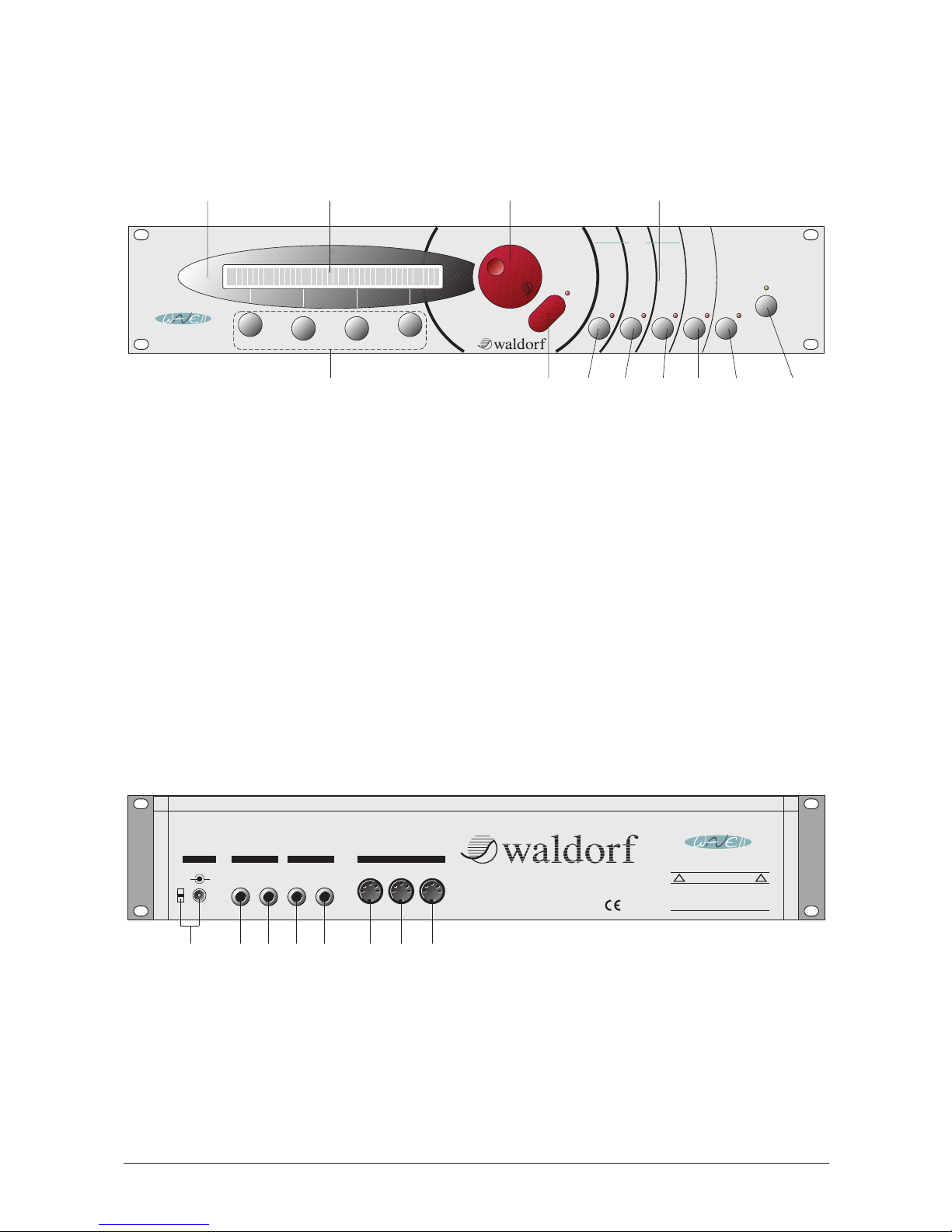
Control Features and Connections of the MicroWave II
Front Panel
Rear Panel
쐃 Power supply socket DC 12V
with cable clip
쐇 Main Out Left/Stereo
쐋 Main Out Right/Mono
쐏 Sub Out Left/Stereo
쐄 Sub Out Right/Mono
쐂 MIDI In jack
쐆 MIDI Thru jack
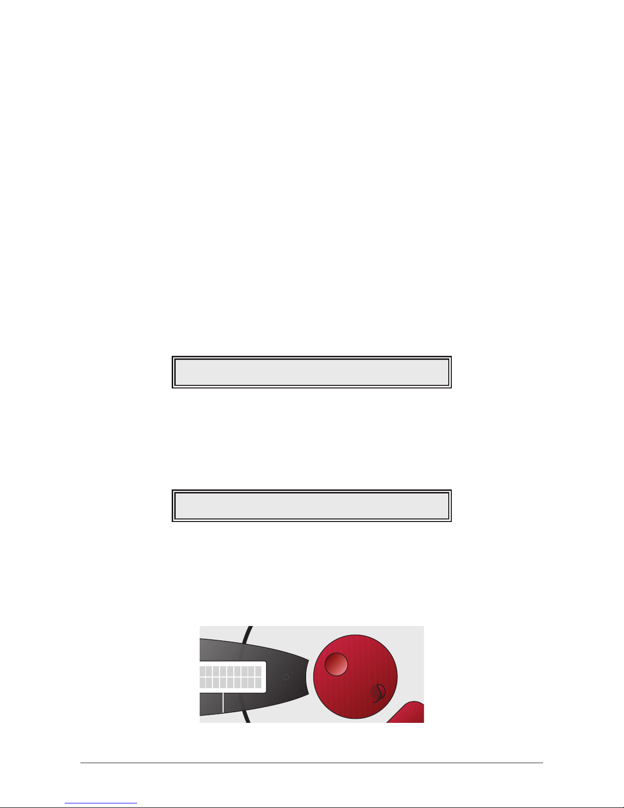
쐊 MIDI Out jack
In OutThru
MIDI
MAIN OUT
Left / Stereo
Right / Mono
Left / Stereo
Right / Mono
SUB OUT
Made in Germany
12V DC 900mA
+
-
POWER
To reduce the risk of electric shock, do not remove cover. No userserviceable parts inside. Refer servicing to qualified service
personnel.
Vorsicht! Gerät nicht öffnen. Gefahr eines Stromschlages.
CAUTION
! !
This device complies
to the FCC rules part
micro
S Y N T H E S I Z E R
쐃 쐇쐋쐏쐄 쐂 쐆 쐊
햲 MIDI status LED
햳 Display
햴 Page dial for selecting sounds and
parameter pages
햵 Parameter pages
햶 Power switch with Standby LED
햷 Select key for sound parameters
Alternate function Utility
햸 Select key for sound parameters
Alternate function Undo
햹 Select key for sound parameters
Alternate function Compare
햺 Select key for multi-/instrument
parameters
Alternate function Recall
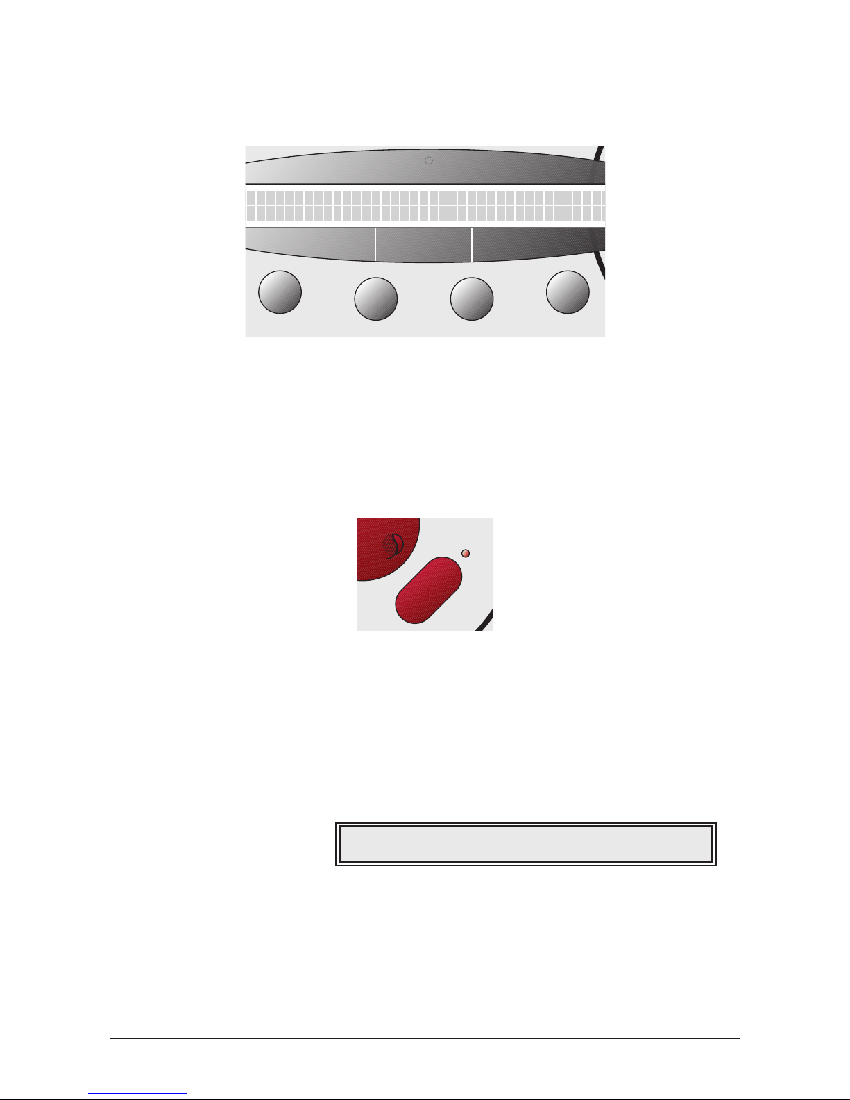
햻 Select key for global parameters
Alternate function Store
햽 Play button for selecting the play
mode
Alternate function Shift
햾 Value dials for adjusting
parameters
Instrument
Store
Instrument
Recall
Filter 1
Compare
Filter Env.
Utility
MIDI
Undo
Volume
Power
Sound / Multi
Multi Global
Osc.1
Osc.2
Wave 1
Wave 2
Quality
Mix
Play Access
Filter 2
Amplifier
Pan
Glide
Trigger
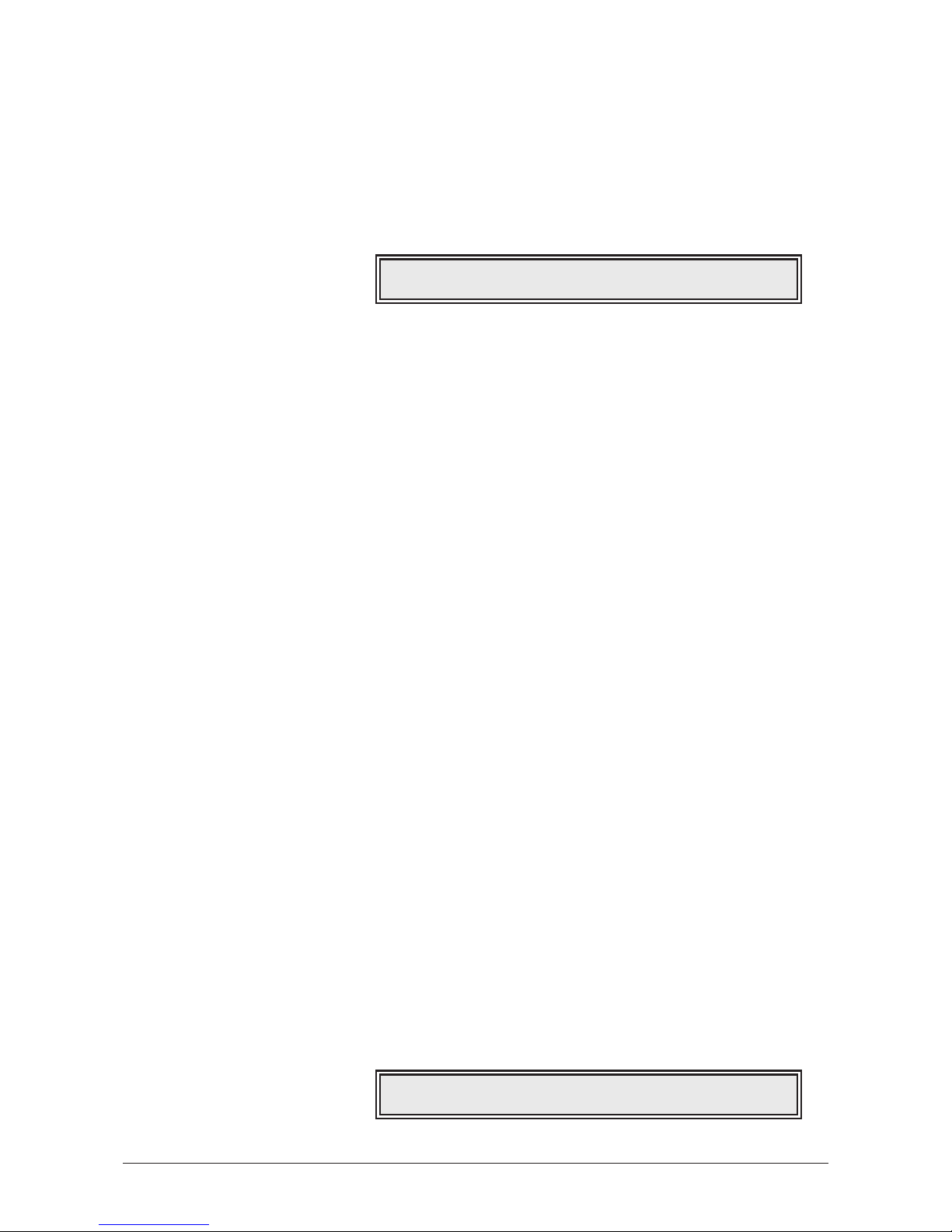
Arpeggiator
Volume Env.
Wave Env.
Free Env.
LFO 1
LFO 2
Modifiers
Mod Matrix
Name
Tempo
Controls
Name
Sound
Tune
Range
Arpeggiator
Controls
Volume
Tables
Tune
System
Sound
Standby
Play
Shift
햲햳 햴 햵
햶햷햽햾
햸
햹
햺
햻
micro
S Y N T H E S I Z E R
User’s Manual MicroWave II • MicroWave XT • XTk
7
Page 8
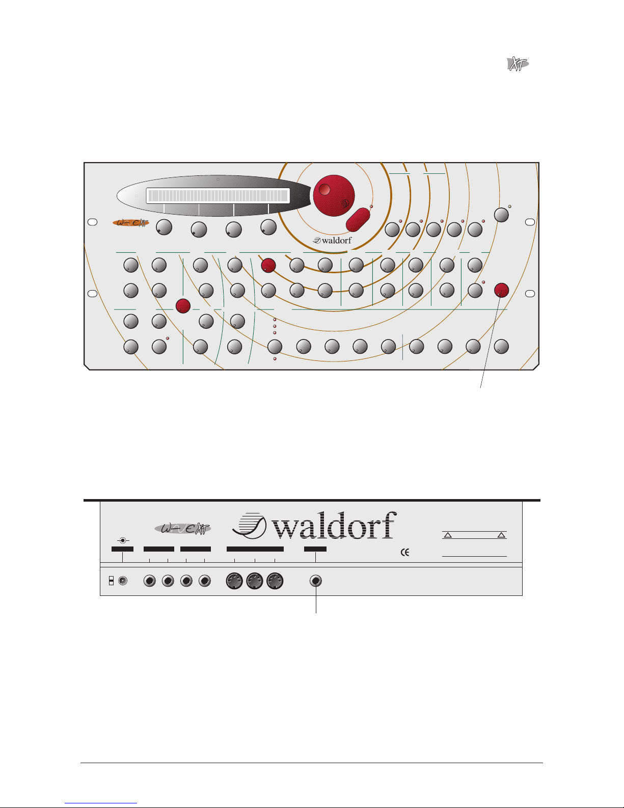
Additional Controls and Connectors of the MicroWave XT
The MicroWave XT features the same controls and connectors as the MicroWave II. In
addition it offers individual controls for the most parameters. The items labeled on this page
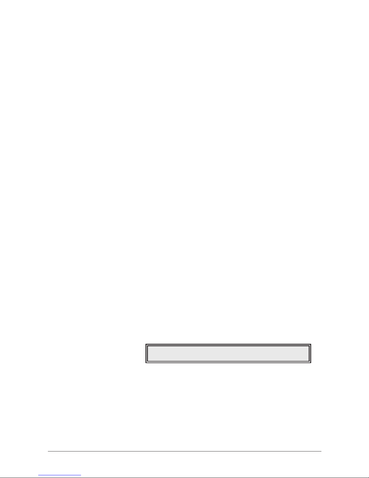
indicate special features that are available on the MicroWave XT only.
Front Panel
Rear Panel
쐎 Analog In jack for processing external audio signals
Made in Germany
MAIN OUT
Left / Stereo
Right / Mono
Left / Stereo
Right / Mono
SUB OUTPOWER
In OutThru
MIDI
ANALOG IN
12V DC 900mA
+
-
S Y N T H E S I Z E R
micro
This device complies to
the FCC rules part 15
To reduce the risk of electric shock, do not remove cover. No userserviceable parts inside. Refer servicing to qualified service personnel.
Vorsicht! Gerät nicht öffnen. Gefahr eines Stromschlages. Servicearbeiten nur von geschultem Fachpersonal durchführen lassen!
CAUTION
! !
쐎
햿 Main Volume rotary control for setting the overall volume.
Free Env
Time 1
Level 1
Time 2
Level 2
Time 3
Level 3 Time 4
Level 4
Wave 1-4
Instrument
Store
Instrument
Recall Compare
Filter Env.
Utility
MIDI
Undo
Volume
Power
Standby
Sound / Multi
Multi Global
Osc.1
Osc.2
Wave 1
Wave 2
Quality
Mix
Play Access Arpeggiator
Volume Env.
Wave Env.
Free Env.
LFO 1
LFO 2
Modifiers
Mod Matrix
Name
Tempo
Controls
Name
Sound
Tune
Range
Arpeggiator
Controls
Volume
Tables
Tune
System
Play
Shift
Octave
Semitone
Wave 1
Startwave
Detune
FM Amount
Env. Amount
Ringmod
Wavetable
Startwave
Octave
Semitone
Wave 2
Sound
Oscillator 1 Mixer
Cutoff
Resonance
Type
Env. Velocity
Env. Amount
Keytrack
Filter
Volume
Env. Velocity
Amplifier
Speed
Speed
ShapeShape
LFO 1 Mod Amount
Time
Active
Glide
Main Volume
Envelopes
Oscillator 2
Wave 1
Wave 2
LFO 2
Env. Amount
Sync
Detune
Noise
Mod 1
Mod 2
Attack
Decay
Sustain
Release
Attack
Decay Sustain
Release
Filter
Amplifier
Filter 1
Filter2
Amplifier
Pan
Effect
Glide
Trigger
Time 1
Level 1
Time 2
Level 2
Time 3
Sustain Release
Rel.Level
Time 5
Level 5
Time 6 Level 6
Time 7
Level 7 Time 8
Level 8
Wave 5-8
S Y N T H E S I Z E R
micro
S Y N T H E S I Z E R
micro
햿
8
User’s Manual MicroWave II • MicroWave XT • XTk
Page 9
Additional Controls and Connectors of the XTk
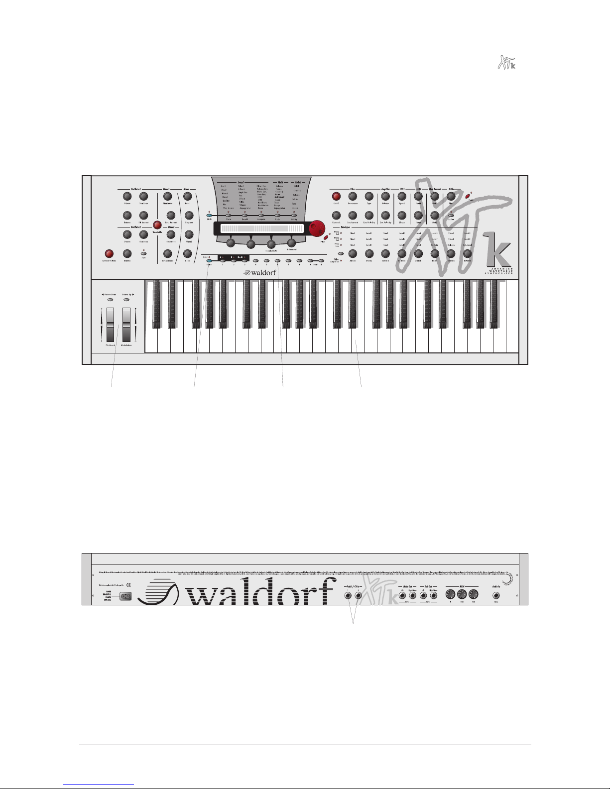
The XTk features the same controls and connectors as the MicroWave XT. In addition it
offers a 4 octave keyboard, a pitchbend and a modulation wheel, as well as numeric keys
and a select button for easy program access. The items labeled on this page indicate special
features that are available on the XTk only.
Front Panel
Rear Panel
쐅 Pedal / CV In jacks for connecting foot controllers or analog voltages
쐅
헀 Keyboard Section
헁 Numeric keys for selecting programs
헂 Select key with Hold led
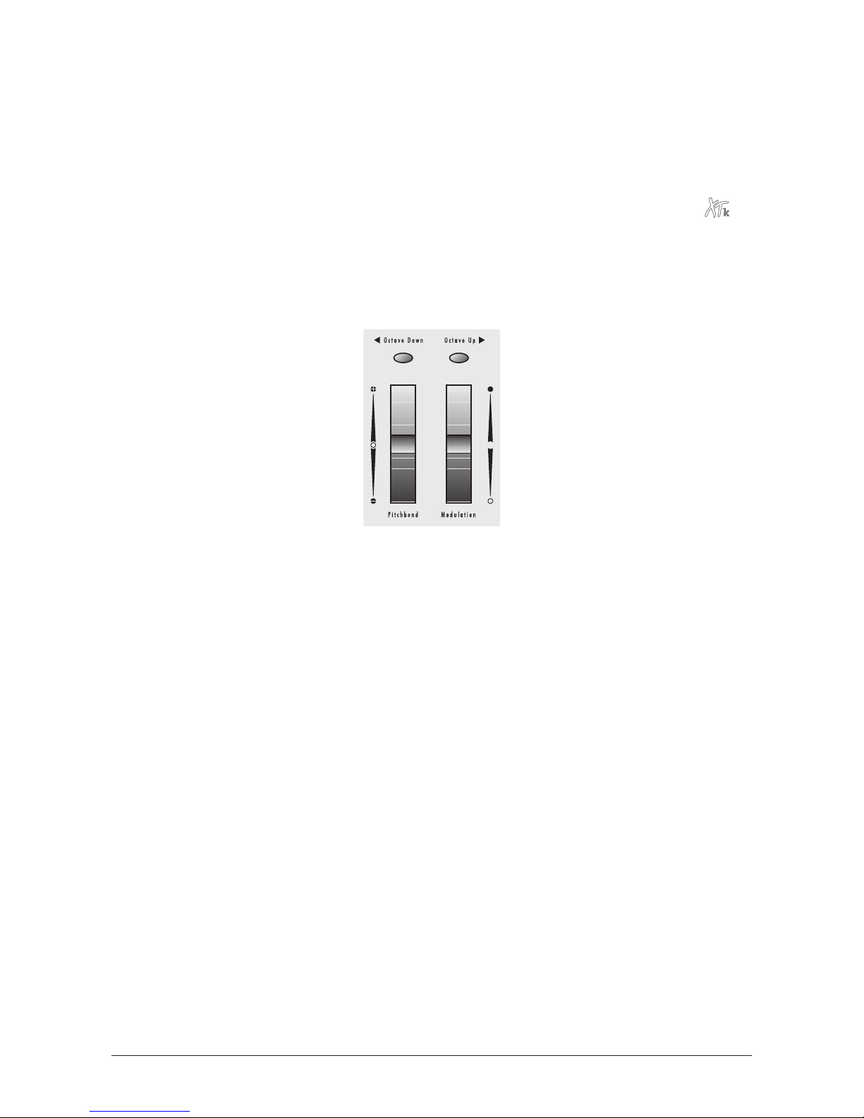
헃 Controller Section with pitchbend wheel, modulation wheel and Octave Up /
Octave Down buttons
헀헁헂헃
User’s Manual MicroWave II • MicroWave XT • XTk
9
Page 10

Foreword
Thank you for purchasing the MicroWave II/XT/XTk. You now own a wavetable synthesizer
featuring a wide range of unique sounds.
To ensure your instrument functions properly and enjoys a long life, please read and heed
the instructions in this manual.
Software development: Stefan Stenzel, Niels A. Moseley, Jürgen Fornoff
Hardware development: Thomas Kircher
Design: Axel Hartmann
Manual: Oliver Rockstedt
Revision Date: 25.10.99
We would like to thank:
Wolfgang Düren, Axel Hartmann, Frank Schneider, Wolfram Franke, Erna Moormann, Beate
Walkowiak, Achim Lenzgen, Claudia Nähring, Martin Neideck, Philipp Dahlhausen, Birger
Degen, Michael Haydn, Dr. Georg Müller, Drew Neumann, Holger "Tsching" Steinbrink,
Gunther Gräfe, Kurt "Lu" Wangard, H.-P. "Bonni" Bonnenberg, Frank Müller, Hubertus
"Hubi" Weller, Sigi Barishi, Holger Bahr, Jörg Hüttner, Piera Caccia, Evi Mognol, Mike
Caroll, Steffi vom Berg, Cordula Müller, Sabine Weiland, Achim Flor, Thilo Kloft, Martin
Herbst, Alex Sauff, Geoff Farr… and anyone we have forgotten.
Very special thanks to the FSF for the GNU Compiler gcc.
Waldorf Electronics is not liable if this manual contains erroneous information. The
contents of this manual may be updated at any time without prior notice. We made every
effort to ensure the information herein is accurate and that the manual contains no
contradictory information. Waldorf extends no guarantees in regard to this manual other
than those required by local law.
This manual or any portion of it may not be reproduced in any form without the
manufacturer's express written consent.
Waldorf Electronics GmbH, Neustraße 12, D-53498 Waldorf, Germany
10
User’s Manual MicroWave II • MicroWave XT • XTk
Page 11
About this Manual
This manual was written to help you become familiar with the Waldorf MicroWave
II/XT/XTk. It will also help experienced users with routine tasks.
To avoid confusion, the terminology in this manual is based on the MicroWave II/XT/XTk
parameter names. You will find a glossary at the end of the manual; it explains the various
terms used herein.
We also used a uniform set of symbols to alert you to topics of particular interest or
significance. Important terms are highlighted in bold letters.
Symbols
Caution: The comments that follow this symbol will help you avoid errors and
malfunctions.
☞Instructions: Follow these guidelines to execute a desired function.
Info: Additional information on a given topic.
Paragraphs marked with this symbol refer to the additional functions of
the MicroWave XT.
Paragraphs marked with this symbol refer to the additional functions of
the XTk.
Highlighted Control Features and Parameters
All of the MicroWave II/XT/XTk’s keys, pots and parameters are highlighted in bold letters
throughout the manual. Also every control element has an unique position no. 햲…헃
which refers to the diagrams at the beginning of this manual. The connectors on the rear
panel are referenced by position no. 쐃…쐅. We suggest you make a copy of this page to
have it at hand when necessary.
Example: • Press the Play key 햽.
The MicroWave II/XT/XTk’s diverse modes and parameter pages are illustrated in a
depiction of the display:
A given parameter’s value range is indicated from low to high with the two values shown in
italic letters, separated by three dots.
Example: Semitone
-12…+12
Octave 1|Semitone | Detune |Keytrack
-2 | +07 | +00 | +100%
User’s Manual MicroWave II • MicroWave XT • XTk
11
Page 12

General Safety Guidelines
Please read the following safety tips carefully!
They include several precautions you should always observe when dealing with
electronic equipment.
Read all of the instructions before operating your device.
Suitable Operating Conditions
• Use the device in enclosed rooms only.
• Never use the device under damp conditions such as in bathrooms, washrooms or
around indoor swimming pools.
• Do not use the device in extremely dusty or dirty environments.
• Ensure adequate ventilation is available at all sides of the device, especially when
you mount it in a rack.
• Do not place the device near heat sources such as radiators.
• Do not expose the device to direct sunlight.
• Do not expose the device to extreme vibrations.
Power Supply
• Use only the included AC adapter (MicroWave II and XT only).
• Plug the adapter only into wall sockets that are properly grounded.
• Make sure the available power supply has the required rating indicated on the
adapter. If you have any doubts, consult a qualified electrician.
• Never install a different plug. If the included cable is not equipped with a suitable
plug for your local sockets, take it to a qualified electrician.
• Unplug the device when you are not using it for longer periods.
• Never touch the plug with wet hands.
• Always pull the plug when unplugging the device, never the cable.
Operation
• Never place objects containing liquids on or near the device.
• Place the device on a stable base only. Use a suitable platform or rack.
• Make sure no foreign objects find their way into the chassis. If for some reason this
should occur, switch the power off, unplug the device and consult a qualified
repair center.
• This device, used on its own or with amplifiers, speakers or headphones, can
generate volume levels that may do irreparable damage to your hearing. For this
reason you should keep the volume at tolerable levels.
12
User’s Manual MicroWave II • MicroWave XT • XTk
Page 13

Maintenance
• Do not open the device or remove the cover. Refer all service and repair tasks to
qualified personnel. The interior of the chassis contains no components that require
user maintenance.
• Use only a dry, soft cloth or brush to clean the device.
Never use alcohol, cleaning solutions or similar chemicals. They will damage the
surface of the chassis.
Proper Use
This device is designed exclusively to produce low-frequency audio signals for the purpose
of generating sound. Any other use is prohibited and voids the warranty extended by
Waldorf Electronics GmbH. Waldorf Electronics GmbH is not liable for damages due to
incorrect use.
User’s Manual MicroWave II • MicroWave XT • XTk
13
Page 14
Setup and Operation
Inventory
The Waldorf MicroWave II/XT/XTk comes complete with:
• the MicroWave II or MicroWave XT or XTk
• 12V/1000mA DC adapter (MicroWave II or XT only)
• warranty card (inside the manual)
• this manual
Please ensure all the items above were included. If something is missing, contact your local
dealer.
We recommend that you save the original packing material for future transport.
Make sure you fill out the warranty card and send it to the appropriate distributor or
the address printed on the registration card. This is the only way we can keep you
informed of upgrades and updates. Other available services are listed on the warranty
card.
Setup
Place the MicroWave II/XT/XTk on a clean, even surface. If you choose to take the device
on the road, we suggest you mount it in a 19" rack or keyboard case. The MicroWave II
takes up 89mm, equivalent to 2 rack spaces, the MicroWave XT takes up 222mm,
equivalent to 5 rack spaces.
Connections
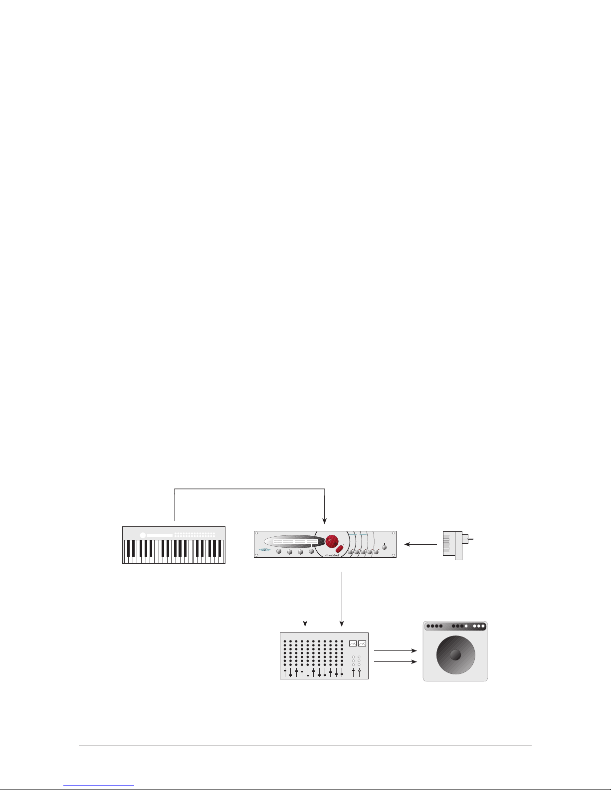
In order to get started with your MicroWave II/XT/XTk you will need an AC wall socket, a
MIDI keyboard, a mixing console, an amp and an audio monitor such as a speaker cabinet.
You can also use a computer or sequencer rather than a MIDI keyboard.
Diagram 1: Connections
Main Out
Right/Mono
Line
In R
Line
In L
MIDI
Out
MIDI
In
MicroWave
Line
Out L
Main Out
Left/Stereo
Line
In L
Line
In R
Line
Out R
Power
MIDI Keyboard
Power
adapter
Mixer
Amp
Instrument
Multi Global
Sound
micro
S Y N T H E S I Z E R
14
User’s Manual MicroWave II • MicroWave XT • XTk
Page 15

☞ Follow these steps to connect the devices:
• Turn all units off.
• Connect the MicroWave II/XT/XTk’s main audio outputs Main Out Left/Stereo 쐇
and Main Out Right/Mono 쐋 to your mixing console. Optionally connect the two
auxilliary audio outputs Sub Out Left/Stereo 쐏 and Sub Out Right/Mono 쐄
too.
• Connect your keyboards MIDI Out jack to the MicroWave II/XT/XTk’s MIDI In jack
쐂. If you own a XTk, you can use the internal keyboard.
• Connect the included adapter to the MicroWave II/XT’s Power Supply 쐃 socket
and fix the wire with the cable clip beside the socket. The XTk model does not
need an ac adapter an can be connected to a wall outlet directly.
• Insert the adapter plug in a suitable wall outlet (MicroWave II or XT only).
• First switch on the connected MIDI keyboard (if any) and then the mixing console
and amp.
If you do not choose to connect a mixing console, you can patch the MicroWave
II/XT/XTk’s output signals directly to an amp. Use an input usually called Aux or Tape
input. If you do not want to send a stereo signal, use the Main Out Right/Mono 쐋
output. If you do not insert a plug into Main Out Left/Stereo 쐇, then the mono
master signal is routed via the right output.
Before connecting and disconnecting the MicroWave II/XT/XTk to a power supply
source, turn your amp’s volume control all the way down to avoid damage due to
on/off switching noise.
The MicroWave II/XT/XTk produces a high level output signal (see technical data).
Please take care that the connected playback device is suitable for the high level of
an electronic instrument.
Never use the mic or phono input of the connected amp!
Analog Input
The MicroWave XT and XTk provides an Analog In jack 쐎 that can be used to feed in an
external signal into the mixer section. Therefore, the signal can be processed via the filters
and the effects section in the same way as the oscillators.
As the external signal is treated like any other sound source within the MicroWave
XT/XTk, it is necessary to trigger the Amplifier Envelope to get the signal passed
through. To do so, notes must be sent to the MicroWave XT/XTk’s sound generation,
either by receiving MIDI notes, the XTk’s keyboard or via the internal arpeggiator.
User’s Manual MicroWave II • MicroWave XT • XTk
15
Page 16
Quick Start
This chapter gives you a quick introduction into the MicroWave II/XT/XTk and its features. It
is written for those people that want to get a quick success without reading tons of manual
stuff. Although the MicroWave II/XT/XTk is a very complex device with many capabilities,
its basic operation is quite easy to understand. But there are also more complicated things
that make it necessary to take a deeper look into this manual from time to time.
Basic Setup
1. Press the Power button 햶 to switch on the MicroWave II/XT/XTk. The display 햳
will show a startup message which disappears after a few seconds.
2. When you want to switch off the power, press and hold the Power button 햶
again. The display now shows a countdown from 10 to 0. When 0 is reached, the
MicroWave is switched off. If you release the Power button before, nothing will
happen. This is just a precaution to prevent data loss by accidently hitting the
button.
3. Before you can start playing the MicroWave II/XT/XTk, you have to ensure that its
MIDI receive channel is set properly. When you power up for the very first time,
channel 1 is selected. To change the setting, press the Utility button 햷. The display
now shows:
Use the first value dial 햾 below the display to change the MIDI receive channel.
Sound Mode
In Sound mode, the MicroWave II/XT/XTk can play one sound at a time. You can select
between 256 Sound programs, which are organised in two banks
A001…B128
and
B001…B128
.
Selecting Sound Programs
1. Press the Play button 햽 to return to the program select page. The display now
shows the program number and the name of the currently selected program:
Play some notes on your MIDI keyboard and listen to the sound.
2. If you want to adjust the MicroWave II/XT/XTk’s volume, use the rightmost value
dial, labeled Main Vol.
3. Use the Page Dial 햴 to select other sound programs. Turning the dial clockwise
increases the program number, turning the dial counterclockwise decreases it. On
the XTk, you can also use the numeric keys 헁 to enter a 2 or 3 digit program
number in the range 001…128.
Editing Sound Parameters via Play Access
Now it is time to do some edits on a sound program. The easiest way for editing sound
parameters is using the so-called Play Access page.
Play Sound A001 | Mode |Main Vol.
Saw Repeat WMF | Sound | 100
Channel |PrgChange|BendRange|Device ID
01 | multi | 012 | 000
16
User’s Manual MicroWave II • MicroWave XT • XTk
Page 17
1. First, switch back to program
A001 Saw Repeat WMF
.
2. Press the Play button 햽 again to access this page. The display then shows 4 sound
parameters that by adjusted directly via the corresponding value dials:
3. Use the value dials to change the sound parameters and listen to the effect on the
generated sound. Actually, you can define the parameter set in this page on your
own. This is described later in the manual.
Comparing edited and original Program
You may always check your modifications against the original version of the program.
Though you can decide whether editing is going the right way or not.
1. Press the Compare key 햹 while holding the Shift key 햽.
2. The MicroWave II/XT/XTk now uses the original parameter values as they were set
before editing was applied. The display also shows these values. Play some notes to
listed to the unedited sound.
3. Press the Compare key 햹 while holding the Shift key 햽 again. This brings you
back to the edited sound program.
Recalling Edits
If you don’t like the changed sound program, you can void the edits at any time and return
to the original.
To do so, press the Recall key 햺 while holding the Shift key 햽.
Storing Programs
After editing the program you have to store it to keep the changes permanent.
1. Press the Store key 햻 while holding the Shift key 햽. The display now shows:
2. Use the rightmost value dial to select a memory location for the edited sound. You
can also leave the setting as it is. In this case you’re going to overwrite the original
sound program. Don’t do it here, we will need it further on in this tour.
3. Press the Store key 햻 while holding the Shift key 햽 again. Your program is now
permanently memorized.
Doing further Edits
We are now moving deeper into the sound editing capabilities of the MicroWave II/XT/XTk.
In the next steps we will show you how specific parameters act on the MicroWave
II/XT/XTk’s behaviour. At first we like to play along with the filter.
1. Switch back to sound program
A001 Saw Repeat WMF
.
2. Press the second parameter select key 햸. This is the same key that is used for the
Recall function, but in this case, it is used without the Shift key 햽. The display
changes to show the parameter page for Filter 1:
Store Sound A001 A001 ?
Saw Repeat WMF
F1 Cutoff|F1 Reso |F1 EnvAmt|FE Decay
092 | 000 | +29 | 084
User’s Manual MicroWave II • MicroWave XT • XTk
17
Page 18
3. Use the first value dial to change the cutoff frequency of the filter. Play some notes
to hear the effect. Reduce the value to get a darker sound. Also change the
resonance setting. The sound gets a narrow character the more you turn up the
control. Rise the setting to its maximum value. You will notice that an additional
tone is generated. This is the self oscillation of the filter!
4. After playing around a little, turn the cutoff down to
70
and the resonance to 20.
This should give you a good starting point for the next step.
5. Turn the Page Dial 햴 clockwise to select the next parameter page. The display
shows:
6. Press a note on your keyboard and hold it down for a few seconds. You may
notice, that the sound starts very bright but then gets darker more and more. This is
the effect of the Filter Envelope that modulates the cutoff frequency. The
modulation depth is controlled here by the Cutoff Env. Amount parameter.
7. Turn its setting down to
0
and look what happens: The sound starts in its dark state
and no cutoff change can be heard.
8. Now set the value to a negative value, e.g.
-10
and press any note again. The
sound then starts much darker than before and gets a little more brilliant after a
while (you may raise the cutoff setting to get better results).
9. After playing around recall the original sound to get prepared for the next step.
The heart of the MicroWave II/XT/XTk are its wavetables. They build the sound source from
which everything derives. In this step we are going to change the sound program’s
wavetable.
1. First, call the first parameter page for Wave 1. To do so, press the first parameter
select key 햷, then use the Page Dial 햴 to select the page. The display must look
like this:
2. Change the wavetable via the third value dial and play some notes. You may notice
that the sound changes dramatically when moving from one wavetable to the next.
Try to check out the following wavetables:
014 Clipper, 021 Robotic,
028 FmntVocal, 054 Wavetrip2
and
060 Xmas Bell
.
3. After checking out the different wavetables, set the parameter back to the original
wavetable
036 PulSync 1
.
The next feature we want to explore is the ring modulation. It is useful to add nonharmonic components to the sound that gives it a metallic character.
1. Use the page dial to select the Mixer page. The display now shows:
Wave 1 | Wave 2 | Ringmod | Noise
127 | 000 | 127 | 000
Startwave| Phase | Wavetable W1
60 | free | 036 PulSync 1
Cutoff Env. Amount|Env.Velocity Amount
+29 | +00
Cutoff |Resonance| Type |Keytrack
092 | 000 | 24dB LP | +050%
18
User’s Manual MicroWave II • MicroWave XT • XTk
Page 19

2. As you can see, the Ringmod parameter is already set to its maximum value. This
is the reason why the basic sound character is so hard. Turn it down and play some
notes. The sound gets much softer.
3. To understand what the ring modulation does, you should listen at its pure signal.
Turn the level of Wave 1 down to
0
and raise Ringmod to
127
again. Play some
notes and listen to the result.
As you have seen in the mixer page, the level of Wave 2 is down at
0
, which means that
the whole sound is made upon one wave. We are now going to use the second wave, too.
1. Initially, turn the levels of Wave 1 and Ringmod down to
0
to get a better
impression what’s going on.
2. Raise the value for the Wave 2 parameter and play some notes. You will notice a
total different „fall down“ sound.
3. Mix in Wave 1 again. Now both sound components are audible. Try to find a good
balance for the levels.
The two waves are driven by two independent oscillators, that means they can have
different pitch setting. Try out the following:
1. Use the page dial to select the Osc 2 1 page. The display now shows:
2. Change the Octave setting and play some notes. Check out
-2
as a value.
The last thing we want to do in our little tour is to work with the envelopes. They determine
the time characteristic of the sound program.
1. Select the Filter Envelope page. You must use the third selection key 햹 to do this.
The display shows:
2. Play some notes on the keyboard and decrease the Decay parameter. You will
notice that the sound gets darker more quickly now.
3. Increase the Attack parameter. The effect you get is that the sound now starts dark
and gets more brilliant. Finally it falls down to its dark state again.
To change the whole sound to a short and percussive hit, we have to use the Volume
Envelope.
1. Select the Volume Envelope page. It is the next page after the Filter Envelope, so
just turn the page dial one step clockwise. The display shows:
2. Decrease the setting of the Decay parameter. The whole sound gets shorter and
shorter. At very low settings you will just hear a kind of click.
AE Attack| Decay | Sustain | Release
000 | 089 | 000 | 019
FE Attack| Decay | Sustain | Release
000 | 084 | 000 | 070
Octave 2|Semitone | Detune |Keytrack
+0 | +00 | +06 | +035%
User’s Manual MicroWave II • MicroWave XT • XTk
19
Page 20
Multi Mode
In Multi mode, you can combine up to 8 sounds. Each sound in a Multi program is called
an Instrument because it has some additional settings that belong to the Multi and therefore
are not stored in the Sound program itself.
The are two main reasons for using a Multi program:
1. Using the MicroWave II/XT/XTk with a sequencer. In that case you want to use
several Sound programs at once, each assigned to a different MIDI channel.
2. Building layered sounds. By doing this you can get interesting combinations e.g. a
chord sound that fades into a string pad.
Of course, you can use both methods in combination.
Selecting Multi Mode
The first thing we have to do is to switch from Sound to Multi mode.
1. Press the Play button 햽 to return to the program select page. The display now
shows the program number and the name of the currently selected program:
2. Turn the third value dial 햾 clockwise. The Mode setting changes to
Multi
. The
display now looks like this:
3. Use the Page Dial 햴 to select other Multi programs. Turning the dial clockwise
increases the program number, turning the dial counterclockwise decreases it.
On the XTk, you can also select Multi mode by pressing the key labeled Multi in the
numeric keys section 헁 while holding the Select button 헂.
Initializing a Multi Program
The best method to create a new Multi program is to initialize an unused program and
adjust the disired parameters.
1. Use the Page Dial 햴 to select an unused program location (e.g. no.
100
).
2. Press the Utility key 햷 while holding the Shift key 햽.
3. Turn the Page Dial 햴 clockwise, until the display shows the Multi Init page:
4. Press the Utility key 햷 while holding the Shift key 햽 again. Your program is now
permanently initialized. The display shows:
Play Multi 100 | Mode |Main Vol.
Init Multi V1.0 | Multi | 100
Init Multi 100 Init Multi ?
[confirm with <Shift-Utility>]
Play Multi 001 | Mode |Main Vol.
Hit Me Bigga WMF | Multi | 100
Play Sound A001 | Mode |Main Vol.
Saw Repeat WMF | Sound | 100
20
User’s Manual MicroWave II • MicroWave XT • XTk
Page 21
The initialization causes the Multi’s parameters to be set to default values. Each Instrument
is assigned to Sound program
A001
and its MIDI receive channel is set to the same value as
the Instrument no. E.g. Instrument no. 5 is set to receive on MIDI channel 5. This default
setting is optimal for sequencer setups.
Selecting Sound Programs for the Instruments
The next step is to select Sound programs for each instrument of the Multi.
1. Press the Multi key 햸 to call the Multi/Instrument parameter pages. The display
now shows the first page of the Multi parameters:
You can set the overall volume for the Multi program here. For now, leave it at its
default value.
2. Use the Page Dial 햴 to select the Sound 1 page:
3. Select a Sound program for Instrument 1 via the second value dial. In our example
we select Program
A018
. Play some notes on the keyboard to listen to the sound.
4. We are now selecting a Sound program for Instrument 2. You can switch between
the Instruments via the fouth value dial. Turn the dial one step clockwise. The
display shows:
5. Select Sound program
B003
for the second Instrument. To change the Bank from
A
to B, use the first value dial.
6. To play Instrument 2, ensure that your master keyboard or sequencer is sending on
MIDI channel 2. Play some notes on the keyboard.
You don’t hear anything? Don’t worry, everything went well, but you have to activate the
Instrument before it works as expected. As default, only Instrument 1 is active after
initializing.
Activating the Instrument
Each Instrument has a Status parameter, where you can turn it on or off. This enables you
to activate only those Instruments, that you really need.
1. Use the Page dial 햴 to select the Sound 2 page:
Bank | Sound Puzzling WMF
B | A003 Inst. #2
Bank | Sound Saw Repeat WMF
A | A001 Inst. #2
Bank | Sound PlayChords WMF
A | A018 Inst. #1
Bank | Sound Saw Repeat WMF
A | A001 Inst. #1
Multi Volume
100 1
User’s Manual MicroWave II • MicroWave XT • XTk
21
Page 22
2. Change the Status setting to on. Now the Instrument is active and you can listen
to it when playing on the keyboard.
The XTk has an extended status setting which allows you to determine whether an
Instrument can be played by MIDI, the internal keyboard or both.
Building a layered Sound
Another exciting feature the Multi mode offeres is the capability to layer sounds. Such a
layered sound consists of two or more Sound programs that are used in combination.
1. Select Instrument 3 and activate it as described above.
2. Choose a Sound program for the Instrument, e.g.
A008 chaOSC
.
3. As expected, you can play the Sound program
A008
on MIDI channel 3. But this is
not what we want to do here. In this case we want to combine it with Instrument 2
which is already setup.
4. The only thing you have to do is to change the MIDI receive channel of Instrument
3 in the Sound 2 page. Use the first value dial to set it to 2.
Both Instruments 2 and 3 now receive on MIDI channel 2 and therefore two Sound
programs are played when you use this MIDI channel. You can layer more Instruments if
you want.
Using an Instrument Arpeggiator
One of the outstanding features of the MicroWave II/XT/XTk is its arpeggiator. In addition to
the arpeggiator that can be used in a Sound program, each Instrument has an arpeggiator,
too. That makes it possible to use arpeggios in a Multi program without editing any Sound
program. You can even use the arpeggiator on Sound programs that normally don’t use one.
1. Select the Arpeggiator 1 page via the Page dial.
2. Select Instrument 2 via the fourth value dial. The display now shows:
3. To activate the arpeggiator, change the Active parameter to on.
4. Now press and hold some keys on the keyboard. Make sure that is sends on MIDI
channel 2 first.
5. You will notice that the sound changes every 2 seconds. This time period is
determined mainly by two parameters: the Clock setting in the currently selected
page and the Multi Arpeggiator Tempo in the Tempo page. Change the Clock
setting to
1/8
and listen what happens: The arpeggio gets faster.
6. Play along with the other arpeggiator parameters and listen to the results.
That’s okay for now. You have seen the basic things, but there is a lot of stuff left. The best
approach to the MicroWave II/XT/XTk is learning by doing and so should you.
Active | Clock | Range
off | 1/1 | 01 Inst. #2
Channel | Volume | Status
02 | 100 | on Inst. #3
Channel | Volume | Status
02 | 100 | off Inst. #2
22
User’s Manual MicroWave II • MicroWave XT • XTk
Page 23
Operation
Power Switching
The MicroWave II/XT/XTk is equipped with a software-based power control, which means it
is initially in standby mode when you supply the device via the AC adapter.
Powering up
Press the Power button 햶 to switch on the MicroWave II/XT/XTk. The Standby LED will
go out.
First, the version number of the MicroWave II/XT/XTk’s operating software will appear in
the display:
After several seconds, the display will change to show the sound program; the MicroWave
II/XT/XTk is now ready to be played.
Switching off
The MicroWave II/XT/XTk has a special shutdown feature, that prevents data loss by accidently pressing the power button. When you want to switch off the power, press and hold
the Power button 햶 again. The display now shows a countdown message from 10 to 0:
After counting down to 0 the MicroWave II/XT/XTk will switch. If you release the Power
button 햶 before, the shutdown process is cancelled.
Adjusting the Master Volume
You can use the rightmost value dial 햾 to adjust the MicroWave II/XT/XTk’s master volume
via the Main Vol. parameter. This setting is global and therefore valid for all programs.
The MicroWave XT and XTk has a dedicated Main Volume rotary control 햿, that can be
used to setup the overall volume. Unlike the other dials, this control is made of a
potentiometer. Adjusting the volume directly affects the global Main Vol. parameter.
Selecting Programs
The MicroWave II/XT/XTk has an internal memory, which is is divided into two different
types of locations:
• 256 Sound programs (Program A001…B128)
In a Sound program, the MicroWave II/XT/XTk can play one sound at a time.
• 128 Multi programs (Program 001…128)
In a Multi program, the MicroWave II/XT/XTk can play up to 8 Sounds
(Instruments) simultaneously, each with individual settings.
All memory locations are freely programmable, so there is no separation into preset and
user programs.
[Switching myself off 8]e |Main Vol.
Saw Repeat WMF | Sound | 100
Waldorf Microwave XT Version 2.18
compiled Wed Aug 11 12:29:17 MET 1999
User’s Manual MicroWave II • MicroWave XT • XTk
23
Page 24
☞ This is how you select a program:
1. Use the Page Dial 햴 to select the appropriated program. Turning the dial
clockwise increases the program number, turning the dial counterclockwise
decreases it.
2. The display shows the program type (Sound or Multi), the program number and the
name of the selected program (name may be different depending on the soundset
loaded):
Numerical Program Select
On the XTk, you can also select programs via the numeric keyboard section. Entering a two
digit or three number will select the corresponding program within the current bank. E.g. to
select program no.
014
, press 1 followed by 4. To select program no.
109
, press 109.
Bank Hold
The Bank Hold function gives further enhancement to the numerical program select. By
"freezing" the two leftmost digits of the program number, programs can be changed by
typing one single digit of the number. This feature is useful especially in live situations.
☞ This is how you use the Bank Hold function:
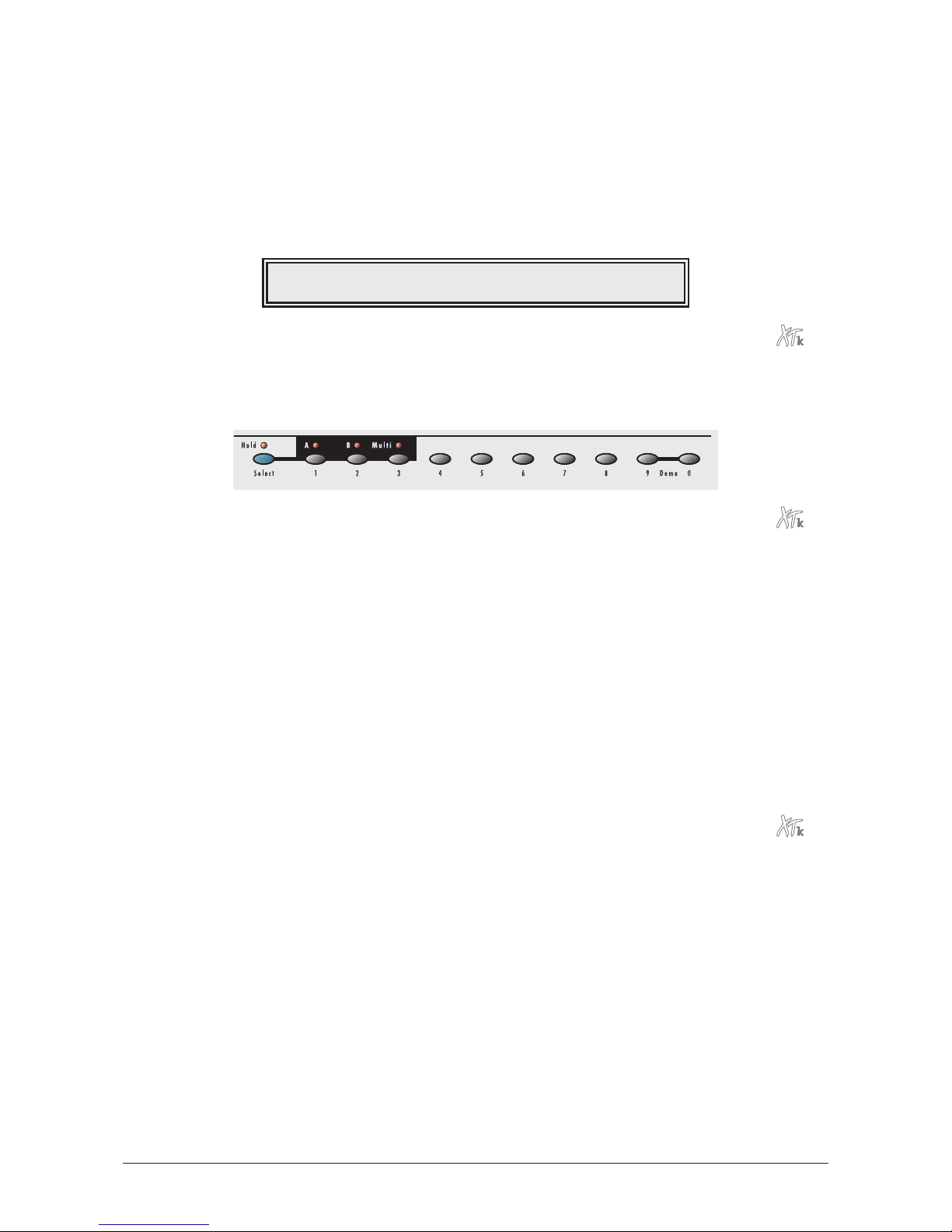
• Press the numerical keys 헁 section’s Select button 헂. The Hold LED above to the
Select button will go on.
• By pressing one of the numerical keys, you can select the last digit of the program
no. E.g. if program no.
A021
was selected before, you can switch from
A020
to
A029
by pressing the corresponding numerical key.
• To terminate the Bank Hold function, press the Select button 헂 again. The LED
above the button will go off again.
Switching Banks
By pressing the corresponding numeric key labeled A or B while holding the Select button
헂, you can easily switch from Bank A to B and vice versa. Before the bank switch is
performed, you have to enter a new 2 or 3 digit program number. This is just a precaution
to avoid "jumping" between programs.
Selecting Sound and Multi Mode
As mentioned before, the MicroWave II/XT/XTk can operate in Sound or Multi mode. When
the MicroWave II/XT/XTk is first powered up, Sound mode is selected.
☞ This is how you select the Multi mode:
1. Turn the third value dial 햾, labeled Mode, clockwise:
2. The display now shows the program number and the name of the selected Multi
program (name may be different depending on the soundset loaded):
Play Sound A001 | Mode |Main Vol.
Saw Repeat WMF | Sound | 100
24
User’s Manual MicroWave II • MicroWave XT • XTk
Page 25
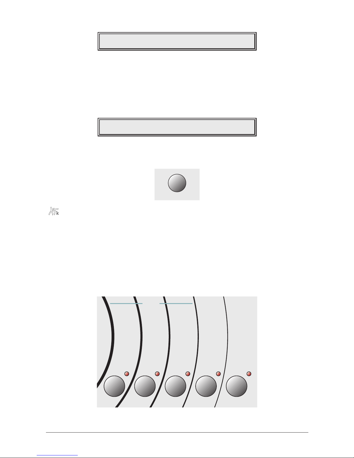
When Multi mode is selected, you can play and edit the multi programs and the single
sounds each program is based upon.
☞ This is how you switch back to Sound mode:
1. Turn the third value dial 햾, labeled Mode, counterclockwise:
2. The display shows the program number and the name of the selected Sound
program again (name may be different depending on the soundset loaded):
You can also switch between Sound and Multi mode when you are not in Play mode e.g.
when editing in a parameter page. To do so, you have to turn the third value dial 햾, also
labeled Sound / Multi, while holding down the Shift key 햽.
The XTk features another method to switch between Sound and Multi mode. Similar to
switching banks, you can activate the Multi mode by pressing the numeric key labeled
Multi while holding the Select button 헂. Switching back to Single mode is done in the
same way by pressing the numeric button A or B while holding Select. Remember that
you still have to enter a 2 or 3 digit program number before the switch is performed.
Editing Parameters
In order to change or edit a sound or multi in the MicroWave II/XT/XTk, you must access
the appropriate parameters. These parameters are arranged in various pages. The front panel
shows the headlines for each parameter page:
Diagram 2: Parameter pages
Store
Instrument
Recall
Filter 1
Compare
Filter Env.
Utility
MIDI
Undo
Volume
Multi Global
Osc.1
Osc.2
Wave 1
Wave 2
Quality
Mix
Play Access
Filter 2
Amplifier
Pan
Glide
Trigger
Arpeggiator
Volume Env.
Wave Env.
Free Env.
LFO 1
LFO 2
Modifiers
Mod Matrix
Name
Tempo
Controls
Name
Sound
Tune
Range
Arpeggiator
Controls
Volume
Tables
Tune
System
Sound
Sound / Multi
Play Sound A001 | Mode |Main Vol.
Saw Repeat WMF | Sound | 100
Play Multi 001 | Mode |Main Vol.
Hit Me Bigga | Multi | 100
User’s Manual MicroWave II • MicroWave XT • XTk
25
Page 26
The picture shows five page groups, divided into the sections Sound, Multi, Instrument
and Global. Each group has a select key 햷…햻 and an activation LED below.
• The Sound parameters refer to a Sound program. If you are in Sound mode, you
will edit the currently played program. If you are in Multi mode, the Sound
program for the currently selected Instrument will be edited.
• The Multi parameters refer to a Multi program. They determine the common setting
for all instruments in the Multi program. Obviously, you can access these
parameters only when the MicroWave II/XT/XTk is in Multi mode.
• The Instrument parameters also refer to a Multi program. They determine the
individual setting of each instrument in the Multi program. Again, you have to be
in Multi mode to access these parameters.
• The Global parameters provide the basic settings of the MicroWave II/XT/XTk,
valid for all programs.
☞ This is how you access a specific parameter:
1. Locate the page group on the front panel and press the corresponding select key
햷…햻 below.
2. The display changes to a set of 4 parameters from the first page of the selected
group. For example, if you press the leftmost select button 햻 the parameters for
Oscillator 1 will be shown:
For a few seconds the page name is shown in the upper right corner of the display.
In our given example
[Osc1 1] will be displayed for "Oscillator 1 Page 1". Some
units of the MicroWave II/XT/XTk, e.g. the oscillators, have several parameter pages
which are indexed by a page number.
When single mode is selected, you can only play and edit sound programs. If you try to
access a Multi mode parameter, you will get an error message in the upper right corner:
If you did some editing before the MicroWave II/XT/XTk was last powered on, the
display may show a different page than the first after pressing the select key. This is an
important feature: The MicroWave II/XT/XTk memorizes the last selected page to
speed up editing. When you re-enter the page group, you will find yourself where
you had left it last time.
3. Use the page dial 햴 to scroll through the page group:
Play Sound A001[Multi Mode not active]
Saw repeat WMF | Sound | 100
Octave 1|Semitone | Detune |Ke[Osc1 1]
-1 | +07 | +00 | +100%
26
User’s Manual MicroWave II • MicroWave XT • XTk
Page 27
Turning the dial clockwise selects the next page, turning it counterclockwise selects
the previous page.
4. Use the value dials 햾 to adjust the corresponding parameters in the display 햳:
Turning a dial clockwise increases the corresponding value, turning it
counterclockwise decreases it. The dials have a built-in dynamic response feature.
If you turn the control slowly, the value changes very smoothly, too. If you turn it
faster, it accelerates as well. This gives you the chance of adjusting the whole value
range in just one turn without losing accurate control when nessessary.
5. When you have finished all your edits you should save the program. Please read
the next topic for further information.
6. Press the Play key 햽 to return to the Play mode:
Edit Buffers
Whenever you edit a Sound or Multi program on the MicroWave II/XT/XTk, the program is
internally copied to an edit buffer. When you use the Store function to save the edits, the
program is copied back from the edit buffer to the internal memory. The MicroWave
II/XT/XTk has 8 separate edit buffers, so you can edit up to 8 programs simultaneously
without storing them. The display shows an e after the program name for every program
that is actually in an edit buffer:
Edit Status
Note that all edit buffers are cleared when switching off the MicroWave II/XT/XTk. Use the
Store function as soon as possible after finishing your edits.
The Compare Function
The Compare function allows you to compare the currently edited sound to its original
stored in the internal memory.
Play Sound A001e | Mode |Main Vol.
Saw Repeat WMF | Sound | 100
Play
Shift
Instrument
Sound / Multi
User’s Manual MicroWave II • MicroWave XT • XTk
27
Page 28
☞ This is how you use the Compare function:
1. Press and hold the Shift key 햽.
2. Briefly press the Compare key 햹.
3. Release the Shift key 햽.
4. The display now shows a c after the program name:
Compare Status
You will now hear the unedited version of your program when you play your MIDI
keyboard.
5. Briefly press the Compare key 햹 while holding the Shift key 햽 again.
6. The c in the display changes to e again. The edited version of the program is now
active again.
Please note that no parameters can be edited when the Compare function is active.
You can only view the original settings. If you select a new program while the
Compare function is active, the Compare status is automatically terminated.
Recalling Edits
You can void edits at any time and return to the original program.
☞ This is how you recall an edited program:
1. Press and hold the Shift key 햽.
2. Briefly press the Recall key 햺.
3. Release the Shift key 햽.
4. The e or c in the the display after the program name is cleared.
All edits have been recalled and the program is back in its original state.
Storing Programs
After you have finished editing a program, you must save it if you intend to use it again. All
memory locations of the MicroWave II/XT/XTk are available for this purpose.
☞ This is how you store a program:
1. Press and hold the Shift key 햽.
2. Briefly press the Store key 햻.
3. Release the Shift key 햽.
4. The display shows a page where you can select the store type, the source and the
destination:
Store
Store Sound A001 A001 ?
Saw Repeat WMF
Play Sound A001c | Mode |Main Vol.
Saw Repeat WMF | Sound | 100
28
User’s Manual MicroWave II • MicroWave XT • XTk
Page 29
5. Use the second value dial to select the store type:
• If
Sound
is selected, the current Sound program will be stored. When used
in Multi Mode, the Sound program of the currently selected instrument will
be stored.
• If
Multi
is selected, the current Multi Program will be stored. The Sound
programs that built the Multi are not stored by this task. You must do this
separately or by using the
All Edits
option. This setting is available in Multi
mode only.
• If
All Edits
is selected, the MicroWave will store back all edit buffers into
their original memory locations. Use this setting to save all edited programs
with a single task.
6. Select the destination program. The default value is the currently selected program
but you may want to change it to store your edits under a different location. This
setting is not available if you choose
All Edits
for the store type.
7. Briefly press the Store key 햻 while holding the Shift key 햽 again.
Whenever you store a program, the selected memory location is overwritten.
Therefore, any previously stored program under this location will be erased and there
is no way to get it back. So, if you want to keep your factory presets you should
dump them to a computer for external storage.
You now have stored the program. When you activate the store function, the Edit or
Compare status of the stored program is terminated.
By pressing any key before performing the last step, you can discard the Store process at
any time.
Use the Store function also if you want to copy programs. There is no need to edit a
program before storing it.
The Play Access Page
The Play Access page is a very exciting feature that gives you an easy accessible control
over 4 freely definable Sound parameters. To select these parameters, please read the
corresponding paragraph in the chapter "Sound Parameters" later on in this manual.
☞ This is how you access the parameters in the Play Access page:
1. When in Play mode, press the Play button 햽 again to call the Play Access page.
The display now shows:
Play Access
2. Use the value dials 햾 to change each parameter’s value.
3. Press the Play button 햽 again to leave the Play Access page and return to the
program select page. You can also you turn the page dial 햴 to select another
program directly.
When the MicroWave II/XT/XTk is in Multi mode, the Play Access page always corresponds
to the Sound program of the currently selected Instrument.
F1 Cutoff|F1 Reso |F1 EnvAmt|FE Decay
092 | 000 | +29 | 084
User’s Manual MicroWave II • MicroWave XT • XTk
29
Page 30
Please note that – like any usual edits – you have to store your modified programs to
make the changes permanent.
Panic Function
The Panic function sends and executes an "All Notes Off" command. It is used to terminate
stuck notes. To activate this function, briefly press the Power button 햶. Note that using
Panic will also stop the arpeggiator playing when running in Hold mode. Panic will
immediately set all envelopes to their release phases. When holding the button a bit longer,
all sound is suppressed and the release phases are overridden.
Randomizing a Program
This functions initializes all parameters of a Sound Program with random values.
☞ This is how you randomize a program:
1. Press and hold the Shift key 햽.
2. Briefly press the Utility key 햷.
3. Release the Shift key 햽.
4. The display shows a page where you can select some utility functions. Most of
them are dump functions. Turn the page dial 햴 clockwise until the display shows:
Randomize
5. Briefly press the Utility key 햷 while holding the Shift key 햽 again.
The selected program is now randomized.
When you randomize a program, all action takes place inside an edit buffer.
Therefore no data will be lost until you store the program.
Initializing Programs
The MicroWave II/XT/XTk provides a special function for setting all parameters of a Sound
or Multi program to initial values. You can use it to create a program from the scratch.
☞ This is how you initialize a program:
1. Press and hold the Shift key 햽.
2. Briefly press the Utility key 햷.
3. Release the Shift key 햽.
4. The display shows a page where you can select some utility functions. Most of
them are dump functions. Turn the page dial 햴 clockwise until the display shows:
Init Sound
Init Sound A001 Saw Repeat WMF ?
[confirm with <Shift-Utility>]
Randomize A001 Saw Repeat WMF ?
[confirm with <Shift-Utility>]
30
User’s Manual MicroWave II • MicroWave XT • XTk
Page 31
If you are in Multi mode, there is a corresponding function to init a Multi program.
You can select it by turning the page dial 햴 one step clockwise again:
Init Multi
5. Briefly press the Utility key 햷 while holding the Shift key 햽 again.
The selected program is now initialized.
When you initialize a program, all action takes place inside an edit buffer. Therefore
no data will be lost until you store the program.
Editing Parameters on the MicroWave XT
In addition to the sound editing capabilities of the MicroWave II/XT/XTk, the XT features
individual control elements for most parameters. This extended user interface offers you a
comfortable way of sound programming.
Dials
When turning a dial on the MicroWave XT panel, the corresponding sound parameter will
be changed. The parameter currently edited is shown in the upper right corner of the
display for a short period of time:
If the parameter is already shown in the display, only the value change will be displayed.
In the envelope section, you can select the active parameter set via the Env. Select button.
When holding the Shift key 햽 while turning a dial, the display changes to the page that
contains the edited parameter. Instead of the Shift key 햽, you can also use the Sync key
in the lower left of the panel.
Buttons
The MicroWave XT features three additional buttons: Sync, Glide and Env. Select.
• The Sync key enables or disables the synchronisation of oscillator 2. Its state is not
shown in the display but via a dedicated LED next to the key. Also, when holding
this key while turning a dial, the corresponding parameter page is called into the
display, as described above.
Play Sound A001 | Mode [Cutoff 059]
Saw Repeat WMF | Sound | 100
Init Multi 001 Hit Me Bigga WMF ?
[confirm with <Shift-Utility>]
User’s Manual MicroWave II • MicroWave XT • XTk
31
Page 32
• The Glide button enables or disabled the glide function. It also uses a dedicated
LED to show the glide state.
• The Env. Select key selects one of four parameter groups for the envelope dials.
The currently selected group is indicated by a LED. The parameters for each group
are printed on the XT panel.
Switching the Octave Setting on the XTk
The XTk features a built-in 4 octave keyboard that can be used to play internal sounds as
well as to generate MIDI notes for external devices. As a default, C1 is the lowest note on
the keyboard, C3 is the middle note and C5 is the highest. To cover a wider octave range,
the whole keyboard can be shifted one octave up or down via the corresponding buttons in
the Controller Section 헃.
☞ This is how you change the keyboard’s octave setting:
1. Press the Octave Down key. The keyboard is shifted one octave down from the
normal setting now, i.e. the whole range is from C0 to C4.
2. Now press the Octave Up key. The keyboard is shifted one octave up from the
normal setting now, i.e. the whole range is from C2 to C6.
3. To return to the default setting, press Octave Down and Octave Up
simultaneously. Now the range is from C1 to C5 again.
32
User’s Manual MicroWave II • MicroWave XT • XTk
Page 33

About Wavetable Synthesis
Basics
The sound generation of the MicroWave II/XT/XTk is based on wavetable synthesis. This
type of synthesis combines analog access and digital flexibility in a simple way. Although
wavetable synthesis is a form of "sample playback" in principle, you should avoid this term
because functionality, operation and results are totally different.
The ROM area of the MicroWave II/XT/XTk currently consists of 65 wavetables, 31
locations are reserved for future ROM wavetables. The RAM area contains 32 user
wavetables, which can be manipulated over MIDI via appropriate computer software.
A wavetable is a list made up of 64 entries. Each entry represents one wave, that can be
either located in the ROM or RAM area of the MicroWave II/XT/XTk or calculated by an
algorithm after selecting the wavetable. For the purpose of using a wavetable inside a sound
program, it doesn’t matter what source the wavetable comes from.
A wavetable itself contains no wave data, but is in fact a collection of up to 64 entries
referencing up to 64 waves. Not all entries of the wavetable have to contain entries. When
one or several sequential entries contain no reference, the MicroWave II/XT/XTk calculates
the waves for these locations automatically. The algorithm producing these "imaginary"
waves uses an interpolation scheme that crossfades the "real" ones. E.g. when a wavetable
cointains entries in entry 1 and 5, the positions 2 to 4 are generated based on interpolation
between the existing waves in entry 1 and 5.
Please keep the terms "wavetable" and "wave" in mind. Don’t bring them into
confusion.
Introduction
Wavetable synthesis gives the MicroWave II/XT/XTk the unique sound character which
makes it different from all other synthesizers and samplers. The principle of wavetable
synthesis is not new, the PPG synthesizer "Wavecomputer 360", "Wave 2", "Wave 2.2" and
"Wave 2.3" and also the Waldorf MicroWave (the first one) and Waldorf Wave use this
concept. The MicroWave II/XT/XTk contains some enhancements to wavetable synthesis
which improve the sonic quality in a remarkable way.
An introduction to wavetable synthesis needs some attention because its operation
principle is different to other sound generating systems. Nevertheless you should spend a
little time in understanding the basics. You will gain more than the effort it takes.
Please note that you cannot create your own wavetables or waves with the
MicroWave II/XT/XTk itself. To do so, you need a wavetable editor, a special
computer program, that allows you to create and edit wavetables and waves. Please
ask your local dealer for such an editor software.
User’s Manual MicroWave II • MicroWave XT • XTk
33
Page 34
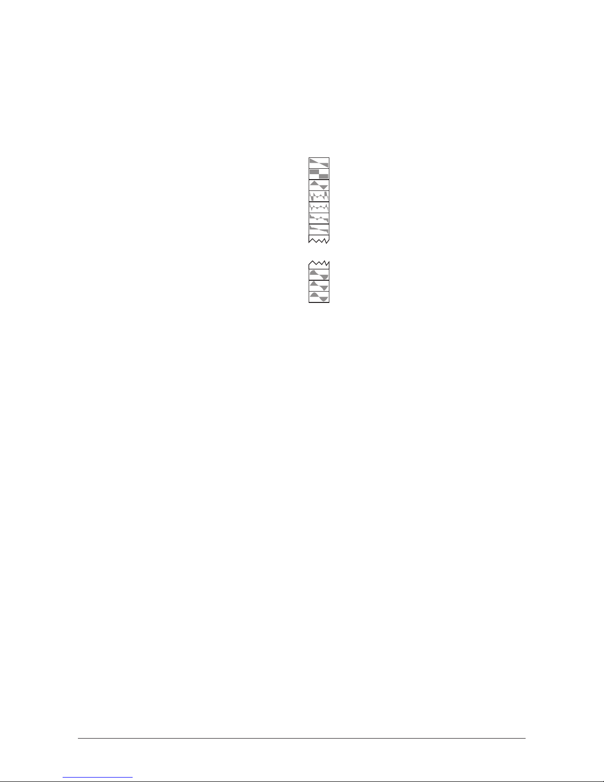
Overview
To illustrate the principle of wavetable synthesis, we start with an overview that is correct in
a scientific way:
A wavetable is a list consisting of 64 waveforms. Each waveform is classified by its own
very special sound character. Some wavetables contain waveforms with a similar sound
character in between, others include waves with extremely different timbres. The following
diagram shows a part of a wavetable.
You will notice, that the upper three entries in the wavetable consist of the classic analog
type waveforms triangle, pulse and sawtooth. These three waves are identical in every
wavetable. You can always use these classic synthesizer waves, independent of which
wavetable is currently selected.
Both oscillators of a MicroWave II/XT/XTk’s voice use a common wavetable. However each
oscillator can play a different waveform inside the list. E.g. oscillator 1 can play a sine wave
from position 1 of the list while oscillator 2 is playing a sawtooth wave from position 63.
The main difference of wavetable synthesis compared to other sound generation principles
is the facility not only to play one waveform per oscillator, but also to walk through the
wavetable via different modulations. Therefore you can create wavetable sweeps. E.g. an
oscillator can start with an sine wave and blend over to a sawtooth wave after some time.
According to the wavetable used, the results can be very drastic – much more than any
sample playback based system could ever produce. That is a unique feature of wavetable
synthesis.
The capabilities of this principle are very strong. To give some examples:
• Each note on a 5 octave keyboard can access a different wave of the wavetable
because such a keyboard has 61 keys, 3 less than the number of wavetable items.
• Different waves can be played depending on key velocity.
• An LFO can modulate the position inside the wavetable. Depending on the
wavetable you can create subtle to drastic sound changes.
• Random controllers like e.g. the modwheel can change the position inside the
wavetable. When you turn the wheel while playing a chord, each note’s wave will
be modified instantly.
These are just a few examples of the capabilities the MicroWave II/XT/XTk’s wavetable
synthesis offers. In the following paragraphs we move deeper into the subject, and by the
way we get a little more specific.
Wave 63
Wave 62
Wave 61
Wave 60
Wave 59
Wave 58
Wave 02
Wave 01
Wave 00
Wave 57
34
User’s Manual MicroWave II • MicroWave XT • XTk
Page 35
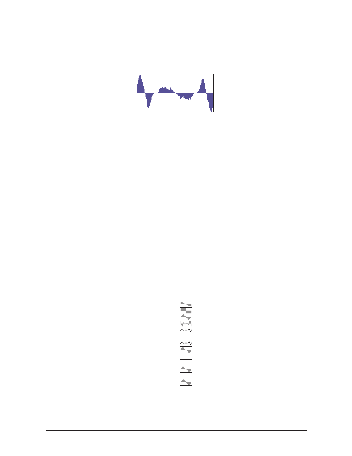
Wave
A wave is the digitally stored image of a single wave cycle. From this point of view a wave
is identical to a sample that is looped exactly after one cycle. The difference to a sampler or
ROM sample player is that all waves have the same length and they are played at the same
pitch. A typical wave looks like this:
The diagram shows the symmetry of the waveform which is mirrored in its middle. In fact
most waves in the MicroWave II/XT/XTk are made up in this way so that only the first half
of the cycle is stored in memory. The MicroWave II/XT/XTk calculates the missing part on
its own. At this point we see one extension to the classic PPG systems and the first
MicroWave: The MicroWave II/XT/XTk can also store whole wave cycles. This feature
becomes interesting in all those cases where analog-type waveforms with different pulse
width or additive created waveforms with different phase shifts of the harmonics should be
generated. These sophisticated timbres were especially not realizable with the first
generation wavetable synthesizers.
Wavetable
In fact a wavetable does not consist of waves but of references to them. The MicroWave
II/XT/XTk stores wavetables and waves separately, numbered from 001…128 for the
wavetables , 000…299 for the waves and 1000…1249 for the user waves.
In a wavetable up to 64 of these references are combined, each pointing at one of the 500
waves. The term "up to 64" means that a wavetable can contain even less references. In this
case the missing entries are filled automatically by the MicroWave II/XT/XTk as soon as the
wavetable is selected. At least 5 references must be present in every wavetable, one at the
first position and 4 at the last. Three of the four positions represent – as already described
above – the classic synthesizer waveforms triangle, pulse and sawtooth.
E.g. the wavetable shown below contains references to waves at positions 00, 02, 05, 60
plus the three classic waves at positions 61…63. We will ignore these three last ones for
now.
Wave 63
Wave 62
Wave 61
Wave 60
Wave 05
Wave 04
Wave 02
Wave 01
Wave 00
Wave 03
User’s Manual MicroWave II • MicroWave XT • XTk
35
Page 36

Now imagine an oscillator sweeping through these wavetable to play one of the waves:
• When position 00 is selected, the oscillator plays the wave referenced by the
wavetable.
• When position 01 is selected, the oscillator plays a wave which is calculated by
the MicroWave II/XT/XTk without being stored in memory directly. The shape of
this wave is interpolated between the shapes of the previous and the next existing
wave, both mixed with different amplitude settings. In the given example a wave
with an amplitude relation of 50% to 50% from the waves on position 00 and 02
would be the result.
• When position 02 is selected, the MicroWave II/XT/XTk plays a "real" wave again,
the one referenced by the list position.
• Position 03 and 04 work similarly to position 01. Again, the waves to be played are
calculated by the MicroWave. In this case the gap is bigger because two positions
in the wavetable are empty. As a result a wave mix of 2/3 to 1/3 (i.e. approx. 66%
to 33%) is generated for wave position 03. As you can see, the previous existing
wave is more weighted here. At position 04 the calculation works vice versa, i.e.
1/3 of wave 02 amplitude and 2/3 of wave 05 amplitude.
• On position 05 a stored wave is played again.
If the oscillator would move up and down between positions 02 and 05, a continious
change of the timbre would be noticed. It is a little bit oversized to call this "continuous"
when not more than 4 positions are available but imagine no further wave references are
stored between position 05 and 60. Then you will get a very smooth timbre change by
moving from position 05 to 60.
And what about hard timbre changes? Now take a look at the classic waveforms on
positions 61…63. As there are not any blank positions between these waves the resulting
timbre changes are very hard.
What else can we do?
In addition to the described structure, the MicroWave II/XT/XTk can generate wavetables
and their corresponding waves via mathematical calculations. Such wavetables are called
"algorithmic wavetables". The speciality about these wavetables is that they don’t need any
real waves to generate interesting timbre changes.
E.g. the calculation scheme for an algorithmic wavetable can be as follows: Take a pulse
wave for position 00 and remove the last samples for every step, so that a single sample
remains on position 60. The result is a wavetable with pulse waves of different pulsewidth.
The different base algorithms for such wavetables are:
• synchronisation
• pulse width modulation
•FM
• waveshaping
Further information regarding algorithmic wavetables is available via internet:
ftp://ftp.waldorf-gmbh.de/pub/waldorf/microwave/upaw/
Summary
You should keep the following sentence in mind because it describes the essentials of the
wavetable synthesis:
36
User’s Manual MicroWave II • MicroWave XT • XTk
Page 37

A wavetable is a list of references to up to 64 waves, in between you can move randomly.
Creating own Wavetables
Sooner or later you want to create your own wavetables and waves. The user interface of
the MicroWave II/XT/XTk is not effective for doing such complex things. Therefore we refer
to corresponding computer software products.
Nevertheless we would like give you a short introduction into the basics of creating
wavetables.
The biggest part of the MicroWave II/XT/XTk’s wavetables contain between 8 and 16 waves,
some of them consist of fewer, some have more. As you can see, you don’t need to fill all
positions of a wavetable with waves to get interesting sweeps. Take your wavetable editor
and look into some of the ROM wavetables. E.g. wavetable 01 is made up of very few
waves while wavetable 28 contains a lot of them.
When you want to create a wavetable that simply fades from a pulse wave to a sawtooth
waveform, you need exactly two waves: The first one, a pulse wave, on position 00 and the
second one, a sawtooth wave, on position 60.
Look into the ROM waves. Consider these waves as a big collection for your own
wavetables. E.g. you will find a sawtooth, a pulse, a triangle and a sine wave already there.
So you can construct a whole new wavetable out of the ROM waves.
History
At the end of 1970, Wolfgang Palm, the founder of PPG, had the idea of recreating the
sound and behaviour of analog circuitries through a digital representation of oscillator
waveforms with different filter settings. He then stored these waveforms sequentially into a
so-called wavetable and added features to scan through this wavetable by envelope, LFO
and the like. The result was a sound that changed its timbre without using any kind of
analog filtering or other processing like FM or ring modulation. These individual timbre
changes that were different from anything else known at that time made up the typical
"wave sound". The first synthesizers built in the early 80s that used this technique were the
PPG 340/380 - Wave Computer and the PPG 360 Wave Computer. Both models yet
without analog filters.
Wolfgang Düren, responsible for the distribution of the PPG synthesizers at that time, was
able to convince Palm to set up analog filters after the oscillators on the follow-up models
PPG Wave 2 and PPG Wave 2.2. The result was synthesizers that wrote history and
influenced the sound of a whole generation.
In the late 80s, PPG discontinued their work and therefore the production of the Wave, but
in the meantime Wolfgang Düren, now manager at Waldorf Electronics, initiated the rebirth
of the Wave’s technology. Based on an extensive cooperation contract with Wolfgang Palm,
the Waldorf MicroWave became the official successor of Wave technology in 1989. The
MicroWave was one of the most influental synthesizers of the late 80s and the 90s, right up
to today. You can find it on almost any important music production from disco through pop
and rock to experimental music. However, the availability of this great synthesizer was not
as immediate as was needed, so it was decided in 1995 to further enhance it and to only
use those electronic parts that we knew were available. This led to the idea of developing
digital filters, and we think we’ve done a pretty good job.
However, we have not forgotten the past: you can still find the original wavetables of the
PPG Wave Computer (Wavetables 001…008), of the PPG Wave 2.2 (009…030, plus the
first 8 wavetables) and of the classic MicroWave (031…064, plus 001…030) in the
MicroWave II/XT/XTk, ensuring that you can still create all famous sounds of those times.
User’s Manual MicroWave II • MicroWave XT • XTk
37
Page 38
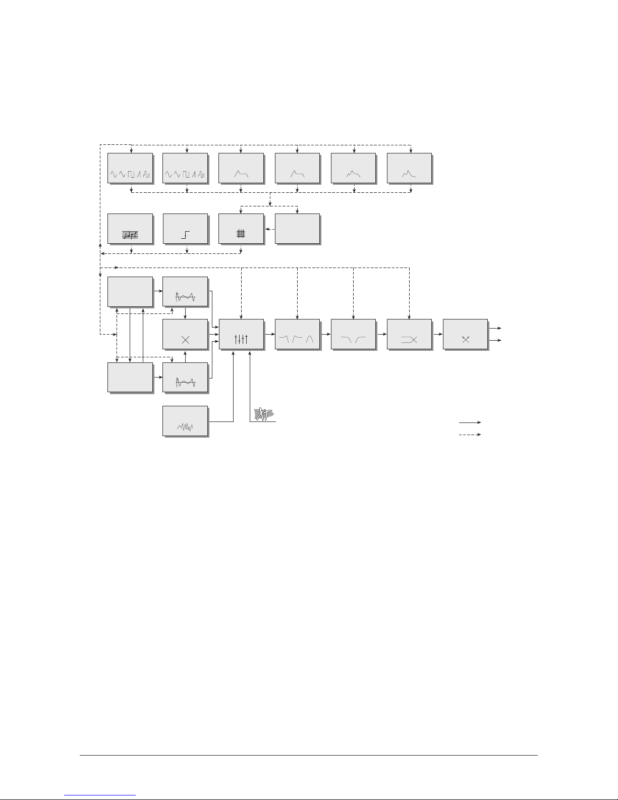
Sound Parameters
Overview of Functions
The Waldorf MicroWave II/XT/XTk consists of numerous sound-shaping components. The
following overview gives you an idea of how the individual components interact:
Diagram 3: Block schematic diagram for single sounds
As you can see, the MicroWave II/XT/XTk consists of two different types of components for
sound generation and sound shaping:
• Oscillators, Waves, Mixer, Filter, Amplifier:
Sound generation actually occurs within the Waves, which are driven by the
Oscillators. They produce a waveform according to the selected wavetable. The
Mixer follows the Waves in the signal chain, which is where the Waves’ output
signals are mixed. Pink noise can also be added to the mix. The Filter then shapes
the sound by amplifying (boosting) or attentuating (dampening) certain frequencies.
The Amplifier is located at the end of the signal chain. It determines the overall
volume and position of the signal within the stereo panorama.
• Modulators: LFOs, Envelopes, Modifiers, Modulation Matrix:
The Modulators are designed to manipulate or modulate the sound generating
components to add dynamics to sounds. The Low-frequency Oscillators (LFOs) are
designed for periodic or recurring waveshapes and Envelopes for modulations that
occur once within a given time frame. These generators are assigned to parameters
via the Modulation Matrix and influence these parameters to alter a sound. In
addition, the Modifier unit can process various mathematical operations and
functions on the modulation signals.
LFO 2LFO 1 Filter Envelope
Amplifier
Envelope
Wave Envelope Free Envelope
Modulation Matrix
Oscillator 1
Oscillator 2
Mixer Filter 1 Amplifier
Output
R
L
Audio signal
Control signal
Ring Modulator
Noise Generator
Arpeggiator Trigger
Filter 2
Modifiers
f(x,y)
Effects
Wave 2
Wave 1
External
Audio Signal
Sync FM
38
User’s Manual MicroWave II • MicroWave XT • XTk
Page 39
Oscillators
The oscillators are the first unit in the chain of the MicroWave II/XT/XTk’s sound generation.
In comparison to a classic analog synthesizer, the oscillator’s output signal itself is not used
as a sound source. It is the driving element for the wavetable synthesis.
Oscillator 1
Osc 1 / 1
Osc 1 / 2
Octave
-4…+4
Determines the octave setting of the oscillator. The reference pitch for the oscillator is
generated at MIDI note A3 (note no. 69) when Octave, Semitone and Detune is set to
0
and Keytrack is
100%
. In this case the oscillator’s frequency will be the same as set in the
global Tune parameter (normally 440Hz). Set this parameter to
0
if you are creating a
typical keyboard sound, set it to
-1
for bass sounds. If you are programming strings or other
high pitched sound, set Octave to
+1
. The following table shows the relationship between
the Octave setting and its corresponding register value, a common measurement based on
the length of organ pipes.
Semitone
-12...+12
Determines the pitch of the oscillator in semitone steps. The standard setting for this
parameter is
0
, but there are cases where different values are required: Most organ sounds
include a quint, therefore one oscillator's semitone parameter must be set to
+7
. There are
also many lead sounds with an interval, e.g. a quart (+5 semitones). When making ring
modulated sounds, try to use
+11
for the setting.
Detune
-64…+63
Fine-tunes the oscillator in increments of 128ths of a semitone. The audible result of
detuning oscillators is a flanging. Use a positive setting for one oscillator and an equivalent
negative setting for the other. A low value of
±1
results in a slow and soft flange effect. Mid-
ranged settings of
±5
are optimal for pads and other fat sounding programs. High values of
±12
or above will give a strong detune that can be used for accordeons or effect sounds.
Setting Register
-4
128ft.
-3
64ft.
-2
32ft.
-1
16ft.
0
8ft.
+1
4ft.
+2
2ft.
+3
1ft.
+4
1/2ft.
Pitchbend Range 1|FM Amount
02 | 010
Octave 1|Semitone | Detune |Keytrack
-2 | +07 | +00 | +100%
User’s Manual MicroWave II • MicroWave XT • XTk
39
Page 40
Keytrack
-100%...+200%
Determines how much the pitch of the oscillator depends on the MIDI note number. The
reference note for Keytrack is E3, note number 64. For positive settings, the oscillator pitch
rises on notes above the reference note, for negative settings the oscillator pitch falls up to
higher notes and vice versa. A setting of
+100%
correspondes to a 1:1 scale, e.g. when an
octave is played on the keyboard the pitch changes for the same amount. Other settings
than
+100%
make sense especially when using ring modulation or oscillator
synchronisation. Try to use values in the range
0…+75%
or even negative settings for one
oscillator while leaving the second at
+100%
Keytrack.
Pitchbend Range
0...120 / harmonic / global
Determines the intensity of the pitchbend via MIDI Pitchbend messages in semitones.
• If
harmonic
is selected, the pitchbend is performed in steps of the harmonic and
the subharmonic scale. The harmonic scale is used when pitch is bended upwards
and built upon multiples of the base pitch. If the base pitch e.g. is 1000Hz, the
harmonic scale consists of 2000Hz, 3000Hz, 4000Hz, 5000Hz... and so on. The
subharmonic scale is used when pitch is bended downwards and built upon
divisions of the base pitch. If the base pitch e.g. is 1000Hz, the subharmonic scale
consists of 500Hz, 333.3Hz, 250Hz, 200Hz, 166.7Hz and so on. The following
example illustrates the harmonic and the subharmonic scale for the note C3:
Harmonic scale: C3, C4, G4, C5, E5, G5, ~A#5, C6, …
Subharmonic scale: C3, C2, F1, C1, G#0, F0, ~D0, C0, …
Please note that the pitches of the harmonic and subharmonic scales differ from
the tempered scale in a considerable way.
• If
global
is selected, the setting in the global parameter BendRange is used.
FM Amount
0…127
Sets the amount that oscillator 2 modulates the frequency of oscillator 1. The sound will get
more metallic and sometimes even drift out of tune, especially if oscillator 2 is synced to
oscillator 1. To avoid unusable detune, use a triangular or sine like wave for oscillator 2.
Oscillator 2
Osc 2 / 1
Osc 2 / 2
Octave
-4…+4
Determines the octave setting of the oscillator. The reference pitch for the oscillator is
generated at MIDI note A3 (note no. 69) when Octave, Semitone and Detune is set to
0
and Keytrack is
100%
. In this case the oscillator’s frequency will be the same as set in the
global Tune parameter (normally 440Hz). Set this parameter to
0
if you are creating a
typical keyboard sound, set it to
-1
for bass sounds. If you are programming strings or other
high pitched sound, set Octave to
+1
.
Pitchbend Range 2| Sync | Link
02 | off | on
Octave 2|Semitone | Detune |Keytrack
+0 | +07 | +00 | +100%
40
User’s Manual MicroWave II • MicroWave XT • XTk
Page 41

Semitone
-12...+12
Determines the pitch of the oscillator in semitone steps. The standard setting for this
parameter is
0
, but there are cases where different values are required: Most organ sounds
include a quint, therefore one oscillator's semitone parameter must be set to
+7
. There are
also many lead sounds with an interval, e.g. a quart (+5 semitones). When making ring
modulated sounds, try to use
+11
for the setting. The semitone setting also becomes very
important when oscillator synchronisation is enabled. Then, Oscillator 1 determines the
pitch of the generated sound, Oscillator 2 determines the colour. Try to use a random
semitone setting while Octave is at
+2
.
Detune
-64…+63
Fine-tunes the oscillator in increments of 128ths of a semitone. The audible result of
detuning oscillators is a flanging. Use a positive setting for one oscillator and an equivalent
negative setting for the other. A low value of
±1
results in a slow and soft flange effect. Mid-
ranged settings of
±5
are optimal for pads and other fat sounding programs. High values of
±12
or above will give a strong detune that can be used for accordeons or effect sounds.
Keytrack
-100%...+200%
Determines how much the pitch of the oscillator depends on the MIDI note number. The
reference note for Keytrack is E3, note number 64. For positive settings, the oscillator pitch
rises on notes above the reference note, for negative settings the oscillator pitch falls up to
higher notes and vice versa. A setting of
+100%
correspondes to a 1:1 scale, e.g. when an
octave is played on the keyboard the pitch changes for the same amount. Other settings
than
+100%
make sense especially when using ring modulation or oscillator
synchronisation. Try to use values in the range
0…+75%
or even negative settings for one
oscillator while leaving the second at
+100%
Keytrack.
Pitchbend Range
0...120 / harmonic / global
Determines the intensity of the pitchbend via MIDI Pitchbend messages in semitones.
• If
harmonic
is selected, the pitchbend is performed in steps of the harmonic and
the subharmonic scale. Please refer to the description for Oscillator 1 to get further
information.
• If
global
is selected, the setting in the global parameter BendRange is used.
Sync
off / on
Enables or disables oscillator synchronisation. When enabled, oscillator 2 acts as a slave
that is controlled by oscillator 1, the master. Each time oscillator 1 starts a new period, it
sends a trigger signal to oscillator 2, forcing it to restart the wave signal, too. As a result,
interesting sound effects may be generated, especially when both oscillators are operating
at different pitch settings. Using additional pitch modulation by envelopes, LFOs or
pitchbend will bring further movement into sync sounds. The following diagram illustrates
the principle of oscillator synchronisation in a simplified way:
User’s Manual MicroWave II • MicroWave XT • XTk
41
Page 42
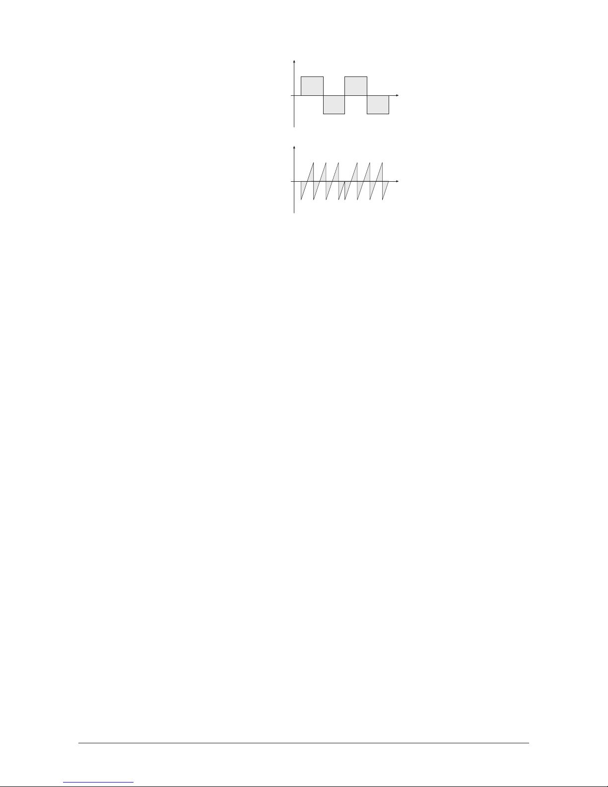
Link
off / on
Allows the same modulation settings for both oscillators to be used. When enabled,
oscillator 2 uses the modulation parameters of oscillator 1 for all modulation matrix settings
and pitchbend messages. That means, whenever a modulation is applied to oscillator 1, it is
also applied to oscillator 2. When disabled, each oscillator uses its own individual
modulation settings.
Oscillator 1
Oscillator 2 in Sync
Time
Level
Time
Level
42
User’s Manual MicroWave II • MicroWave XT • XTk
Page 43
Waves
The waves are the sound sources of the MicroWave II/XT/XTk. They are driven by the
oscillators‘ output signal and define the basic spectrum of the generated sound. Please refer
to the corresponding topic of this manual to get further information about the wavetable
synthesis.
Wave 1
Wave 1 / 1
Wave 1 / 2
Although the Wavetable parameter is the third entry in the Wave 1 / 1 page, it will be
explained as the first parameter of these pages. This is because the wavetable defines
the basic character of the complete sound. The selected wavetable is used for both
wave generators, although it is only displayed in the Wave 1 / 1 page.
Wavetable
001...128
The Wavetable parameter selects the wavetable for both waves 1 and 2. Each wavetable has
a number and a name. The following table shows an overview of all available wavetables
and their names:
Table 1: Wavetable overview
The wavetables
065…128
contain no factory presets. The locations
065…096
are reserved
for future use. Memory locations
097…128
are User Wavetables.
Although the selected wavetable is used for both waves, it is only displayed in the
currently explained parameter page.
The Wavetables are the real power of the MicroWave II/XT/XTk. To make sure that you have
access to all this power, you should make yourself familiar with the sound and the
characteristic of each wavetable. The best way to do so is to set up a kind of test sound to
001 Resonant
002 Resonant 2
003 MalletSyn
004 Sqr-Sweep
005 Bellish
006 Pul-Sweep
007 Saw-Sweep
008 MellowSaw
009 Feedback
010 Add Harm
011 Reso 3 HP
012 Wind Syn
013 High Harm
014 Clipper
015 Organ Syn
016 SquareSaw
017 Formant 1
018 Polated
019 Transient
020 ElectricP
021 Robotic
022 StrongHrm
023 PercOrgan
024 ClipSweep
025 ResoHarms
026 2 Echoes
027 Formant 2
028 FmntVocal
029 MicroSync
030 Micro PWM
031 Glassy
032 Square HP
033 SawSync 1
034 SawSync 2
035 SawSync 3
036 PulSync 1
037 PulSync 2
038 PulSync 3
039 SinSync 1
040 SinSync 2
041 SinSync 3
042 PWM Pulse
043 PWM Saw
044 Fuzz Wave
045 Distorted
046 HeavyFuzz
047 Fuzz Sync
048 K+Strong1
049 K+Strong2
050 K+Strong3
051 1-2-3-4-5
052 19/twenty
053 Wavetrip1
054 Wavetrip2
055 Wavetrip3
056 Wavetrip4
057 MaleVoice
058 Low Piano
059 ResoSweep
060 Xmas Bell
061 FM Piano
062 Fat Organ
063 Vibes
064 Chorus 2
065 True PWM
EnvAmount|EnvVelAmt|Keytrack |Limit W1
-20 | +15 | +068% | off
Startwave| Phase | Wavetable W1
057 | 132¡ | 001 Resonant
User’s Manual MicroWave II • MicroWave XT • XTk
43
Page 44

listen to the wavetables: Start with an initialized sound and turn down the mix level of
Oscillator 2. In the Mod Matrix, setup a modulation that uses the ModWheel to modulate
Wave1Pos and set the amount to
+62
(the setting of
+62
instead of
+63
prevents that you
accidentally access the "analog" waveforms explained below). Now you can use the
Modulation Wheel to sweep through the whole selected wavetable. Change the Wavetable
parameter to see how the different wavetables sound. You will notice that they cover an
extremely wide range of interesting spectral timbres, including analog, FM-like, bell-type or
vocal.
Startwave
00...60 / triangle / square / sawtooth
Determines the start point of the wavetable that is used when the sound starts. As an
alternative to the waves of the currently selected wavetable, you can select the basic
waveforms
triangle, square
with 50% duty cycle or
sawtooth
.
When you want to create a sound with a wave sweep, you should roughly set the Startwave
parameter onto the desired wave, before you apply any modulations to the corresponding
Wave module. This helps you to find the basic waveform where all modulations start from.
Note that you can apply unipolar and bipolar modulation sources to the Wave module as
with any other module. For example, set the Startwave parameter to
29
, which is almost the
middle of the wavetable and apply a slow running LFO to the Wave module to sweep
through the whole wavetable (except the three waveforms triangle, square or sawtooth). Try
it with one of the PWM wavetables.
The basic waveforms triangle, pulse and sawtooth correspond to entry
61…63
of
each wavetable. Please notice, that these waveforms are also used when an
appropriate wave modulation is applied. To avoid this, you will have to activate the
Limit parameter. Please read this corresponding topic to get further information. Use
the basic waveforms to generate traditional, analog synthesizer sounds.
Phase
free / 3...357°
By means of this parameter you can define the startsample and, as a result, the phase of the
generated wave. Alternative to a fixed value, you can use
free
to set the phase to a different,
random value each time a note is generated. The setting is scaled in degrees.
EnvAmount
-64…+63
Determines the amount of influence the wave envelope has on the wavetable modulation.
EnvVelAmt
-64…+63
Determines the amount of influence the wave envelope has on the wavetable modulation,
based on key velocity. In conjunction with EnvAmount you can create nice effects when
you set one of the two parameters to a negative setting while the other one is set to a
positive setting.
Keytrack
-200%…+197%
Determines the amount of wavetable modulation depending on the received MIDI note
number. Reference note for this parameter is E3, note number 64. For positive settings the
modulation amount is increased for notes above to reference note, for negative settings the
amount is decreased. A setting of
+100%
corresponds to a 1:1 scale. This means that each
note above or below the reference note plays a different wave. E.g., when you set
Startwave to
29
and Keytrack to
+100%
, it means that E3 plays wave 29, F3 plays wave
30, F#3 plays wave 31 and so on.
44
User’s Manual MicroWave II • MicroWave XT • XTk
Page 45
Limit
off / on
This setting prevents, if enabled, accessing the analog type waveforms triangle, square and
sawtooth in any case of modulation. When disabled, the full modulation amount will be
calculated and applied so that the whole wavetable will be used for tone generation.
Wave 2
Wave 2 / 1
Wave 2 / 2
Startwave
00...60 / triangle / square / sawtooth
Determines the start point of the wavetable that is used when the sound starts. As an
alternative to the waves of the currently selected wavetable, you can select the basic
waveforms
triangle, square
with 50% duty cycle or
sawtooth
.
When you want to create a sound with a wave sweep, you should roughly set the Startwave
parameter onto the desired wave, before you apply any modulations to the corresponding
Wave module. This helps you to find the basic waveform where all modulations start from.
Note that you can apply unipolar and bipolar modulation sources to the Wave module as
with any other module. For example, set the Startwave parameter to
29
, which is almost the
middle of the wavetable and apply a slow running LFO to the Wave module to sweep
through the whole wavetable (except the three waveforms triangle, square or sawtooth). Try
it with one of the PWM wavetables.
The basic waveforms triangle, pulse and sawtooth correspond to entry
61…63
of
each wavetable. Please notice, that these waveforms are also used when an
appropriate wave modulation is applied. To avoid this, you will have to activate the
Limit parameter. Please read this corresponding topic to get further information. Use
the basic waveforms to generate traditional, analog synthesizer sounds.
Phase
free / 3...357°
By means of this parameter you can define the startsample and, as a result, the phase of the
generated wave. Alternative to a fixed value, you can use
free
to set the phase to a different,
random value each time a note is generated. The setting is scaled in degrees.
Link
off / on
Allows the use of the same modulation settings for both waves. When enabled, wave 2 uses
the modulation parameters of wave 1 for all Modulation Matrix settings, EnvAmount,
EnvVelAmt and Keytrack. That means, whenever a modulation is applied to wave 1, it is
also used for wave 2. When disabled, each wave uses its own individual modulation
settings.
EnvAmount
-64…+63
Determines the amount of influence the wave envelope has on the wavetable modulation.
EnvAmount|EnvVelAmt|Keytrack |Limit W2
-20 | +15 | +050% | off
Startwave| Phase | Link W2
057 | free | off
User’s Manual MicroWave II • MicroWave XT • XTk
45
Page 46

EnvVelAmt
-64…+63
Determines the amount of influence the wave envelope has on the wavetable modulation,
based on key velocity. In conjunction with EnvAmount you can create nice effects when
you set one of the two parameters to a negative setting while the other one is set to a
positive setting.
Keytrack
-200%…+197%
Determines the amount of wavetable modulation depending on the received MIDI note
number. Reference note for this parameter is E3, note number 64. For positive settings the
modulation amount is increased for notes above to reference note, for negative settings the
amount is decreased. A setting of
+100%
corresponds to a 1:1 scale. This means that each
note above or below the reference note plays a different wave. E.g., when you set
Startwave to
29
and Keytrack to
+100%
, it means that E3 plays wave 29, F3 plays wave
30, F#3 plays wave 31 and so on.
Limit
off / on
This setting prevents, if enabled, accessing the analog type waveforms triangle, square and
sawtooth in any case of modulation. When disabled, the full modulation amount will be
calculated and applied so that the whole wavetable will be used for tone generation.
46
User’s Manual MicroWave II • MicroWave XT • XTk
Page 47
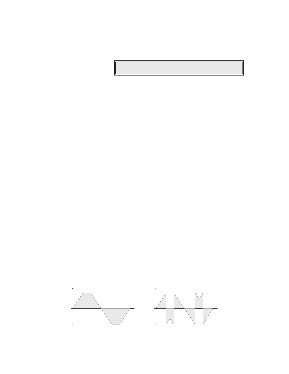
Quality
The quality parameters control the input stage of the Mixer. They determine the amount of
Aliasing and Time Quantization applied to the sound as well as the type of distortion
generated when the signal raises the clipping level.
Quality
Aliasing
off / 1…5
Aliasing is a digital artefact that is audible as soon as a wave has harmonics higher than
half the sampling frequency. Usually, aliasing is reduced to a minimum by some magical
mathematics, but here you can override this and listen to aliasing distortion just like in the
dawn of the first digital musical instruments like the PPG Wave or the first MicroWave. Use
a setting other than
off
for sounds that expressionally should have a "digital" character.
TimeQuant
off / 1…5
With a wave, 64 harmonics including the fundamental frequency can be represented, and a
clever interpolation algorithm makes sure only these 64 harmonics are generated, even at
low pitches. However, sometimes one might wish to add additional harshness at the lower
end, just like the first MicroWave did, and this is what Time Quantization is for: The wave
interpolation is overridden in five steps to get this extra fizziness. Note that pitch accuracy
is a bit diminished when using a value other than "off". The audible result of Time
Quantization is a very sharp sound character when playing at low pitches. Use this e.g. for
sawtooth based sounds.
Accuracy
off / on
If disabled, voices are detuned very slightly to give more vivid sound, especially when
playing chords or sounds with long release. If enabled, the tuning is done as accurate as
possible.
Clipping
saturate / overflow
Selects the type of distortion that is applied when the signal raises the clipping level.
Clipping is always generated when the sum of all mixer input volumes (i.e. Wave 1, Wave 2
Noise and Ringmodulation) exceeds 128.
• If
saturate
is selected for this parameter, the signal will be limited to the maximum
level. This is the kind of distortion classic analog circuits will generate.
• If
overflow
is selected, distortion is proceeded in the same way as a numerical
overflow in a digital system: The polarity of the signal’s part above the maximum
level will be negated.
Time
Level
overflow
Time
Level
saturate
max
min
max
min
Aliasing |TimeQuant|Accuracy |Clipping
3 | off | off |saturate
User’s Manual MicroWave II • MicroWave XT • XTk
47
Page 48
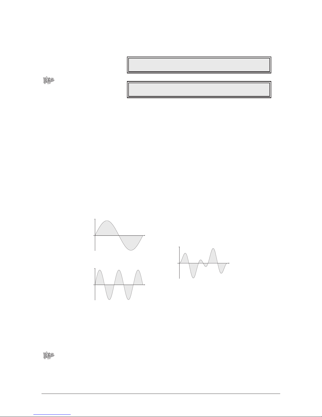
Mixer
In the mixer you control the volumes of both waves and the noise generator. An optional
ring modulation extends the tonal range of the MicroWave II/XT/XTk.
Mixer
Mix 2
Wave 1
0…127
Volume of Wave 1.
Wave 2
0…127
Volume of Wave 2.
Ringmod
0…127
Volume of the ring modulation between Wave 1 and 2. From a technical point of view ring
modulation is the multiplication of the waves’ signals. The result of this operation is a
waveform that contains the sums and the differences of the source frequency components.
Since the ring modulation generates disharmonic components, it can be used to add
metallic distorted sound characteristics. This is useful e.g. when generating synth
percussion. The following diagram illustrates what happens when two sine waves are ring
modulated. Please note that in a complex waveform all harmonic component behave like
interacting sine waves, resulting in a wide spectral range of the ring modulated sound. The
following diagram illustrates the ring modulation of two sine waves:
Noise
0…127
Volume of the noise generator. The noise generator produces pink noise and features no
other controls. Noise is a fundamental source for any kind of analog-type percussion. Also
wind and other sound effects can be created by using the noise generator.
External
0…127
Volume of the external audio input Analog In 쐎. Please note that if you use an external
sound source, you still have to trigger the MicroWave XT’s envelopes to get the signal
passed through. Though you have to generate MIDI notes either by a connected sequencer
or the internal arpeggiator.
Time
Level
Time
Level
Time
Level
Wave 1
f
1
= 1
Wave 2
f
2
= 2,5 (1 octave + 4 semitones)
Ring Modulation
f
res1
= f1-f2 = 1,5
f
res2
= f1+f2 = 3,5
External
123
Wave 1 | Wave 2 | Ringmod | Noise
113 | 56 | 0 | 13
48
User’s Manual MicroWave II • MicroWave XT • XTk
Page 49
Play Access
The Play Access page is a very exciting feature that gives you an easy accessible control
over 4 freely-definable Sound parameters. This can be extremly useful in adapting a sound
very quickly as well as having easy realtime control in performance situations.
In fact the Play Access function consists of two parts:
• Defining the parameters for the Play Access page.
• Accessing the previously defined parameters.
Defining the parameters
Play Access
Par #1…Par #4
sound parameters
Use the value dials 햾 to select the desired parameters. Turning the dials will scroll the view
through a list of the most important single sound parameters that are available on the
MicroWave II/XT/XTk. Some parameter names are abbreviated to fit in the display area. E.g.
AE Attack
stands for the Amplifier Envelope Attack parameter. The following table shows an
overview of the used abbreviations.
Table 2: Play Access abbreviations
Abbreviation Description
Osc1
Oscillator 1
Osc2
Oscillator 2
W1
Wave 1
W2
Wave 2
Mix
Mixer
F1
Filter 1
F2
Filter 2
Amp
Amplifier
Arp
Arpeggiator
FE
Filter Envelope
AE
Amplifier Envelope
Abbreviation Description
Oct
Octave
Semi
Semitone
Det.
Detune
Bend
Pitchbend Range
Keyt / Keytrk.
Keytrack
StartW
Startwave
EnvAmt
Envelope Amount
VelAmt
Velocity Amount
Ring
Ring Modulation
Reso
Resonance
Vol
Volume
Pan
Panning
Patt.
Pattern
Dir.
Direction
Velo
Velocity
Alloc.
Allocation
Sust.
Sustain
Shpe
Shape
Dlay
Delay
Sync
Synchronisation
Sym.
Symmetry
Hum.
Humanize
Phas
Phase
Par #1 | Par #2 | Par #3 | Par #4
Arp Dir. |Arp Order|LFO1 Shpe|Osc2 Keyt
User’s Manual MicroWave II • MicroWave XT • XTk
49
Page 50
Here are some examples of useful parameter sets for the Play Access page.
Example 1
Example 2
Example 3
Example 4
Please note that the Play Access setting is stored in the sound program like the other
sound parameters. Therefore you must save your program even if you only changed
the Play Access definitions. By handling them as part of a sound, you will get the
chance of having different settings for each program.
Accessing the previously defined parameters
☞ This is how you access the selected parameters in the Play Access page:
1. Press the Play button 햽 twice to switch back to performance mode and call the
Play Access page. The display now shows:
2. You can now use the value dials 햾 to change each parameter’s value.
Please note that – like any usual edits – you have to store your modified program to
make the changes permanent.
F1 Cutoff|F1 Reso |F1 EnvAmt|FE Decay
092 | 000 | +29 | 084
Par #1 | Par #2 | Par #3 | Par #4
Effect | Assign |Panning |Glide
Par #1 | Par #2 | Par #3 | Par #4
ArpActive|Arp Tempo|Arp Clock|Arp Patt.
Par #1 | Par #2 | Par #3 | Par #4
W1 StartW|W2 StartW|Mix Ring |Glide
Par #1 | Par #2 | Par #3 | Par #4
F1 Cutoff|F1 Reso |F1 EnvAmt|FE Decay
50
User’s Manual MicroWave II • MicroWave XT • XTk
Page 51
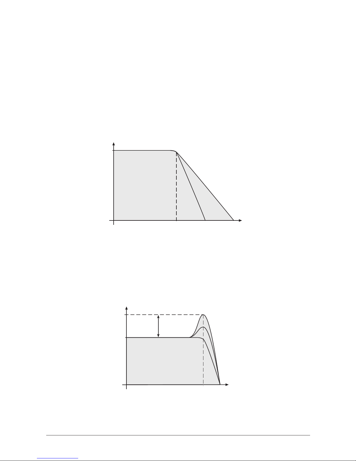
Filter
Once the audio signal leaves the mixer, it is sent to the filters. The MicroWave II/XT/XTk has
two independent filter units, each with its own individual settings. Both filters are routed in
series. The filters are components that have significant influence on the MicroWave
II/XT/XTk’s sound characteristics.
The filter type most commonly used in synthesizers is a low pass filter. This type dampens
frequencies that lie above a specified cutoff frequency. Frequencies below this threshold are
hardly affected. The frequency below the cutoff point is called the pass band range, the
frequencies above are called the stop band range. The MicroWave II/XT/XTk’s filter
dampens frequencies in the stop band with a certain slope. The slope is selectable between
12dB and 24dB per octave. This means that the level of a frequency that lies an octave
above the cutoff point will be 12dB or 24dB less than those frequencies of the signal that
fall into the pass band. The following diagram shows the basic principle of a low pass filter:
To give you an idea of the extent of damping, consider this: A reduction of 24dB reduces
the original level by approx. 94%. The damping factor two octaves above the cutoff point
reduces the original level by more than 99%, which in most cases means this portion of the
signal is no longer audible.
The MicroWave II/XT/XTk’s filter also features a resonance parameter. Resonance in this
context means that a narrow frequency band around the cutoff point is emphasised. The
following diagram shows the effect of the resonance parameter on the filter’s frequency
curve:
If the resonance is raised to a great extent, then the filter will begin self-oscillation, i.e. the
filter generates an audible sine wave even when it does not receive an incoming signal.
Frequency
Level
Cutoff
Resonance
Frequency
Level
Cutoff
24dB/Oct 12dB/Oct
User’s Manual MicroWave II • MicroWave XT • XTk
51
Page 52
Filter 1
Filter 1 gives you the most flexibility by offering low pass, high pass and band pass types. In
addition, there is an sine waveshaping filter with an 12dB low pass following. You can
select the slope between 12dB and 24dB per octave for the low pass and band pass.
Further types might be added in the future.
Filter 1 / 1
Filter 1 / 2
Cutoff
0…127
Determines the cutoff frequency for the low pass and high pass filter types and the mid
frequency for the band pass type. When a low pass is selected via the Type parameter, all
frequencies above the cutoff frequency are damped. When high pass is selected, all
frequencies below the cutoff frequency are damped. In a band pass only frequencies near
the cutoff setting will be passed through. You can bring more movement into the sound by
modulating the cutoff frequency via the LFOs, the envelopes or the Keytrack parameter. At
a value of
64
and a Resonance value of
114
, the filter oscillates with 440Hz, which is
equal to A3. Tuning is scaled in semitone steps. When Keytrack is set to
+100%
, the filter
can be played in a tempered scale.
Resonance
0…127
Filter resonance parameter. Determines the amplification of the frequencies around the
cutoff point. Use lower values in the range
0…80
to give more brilliance to the sound. At
higher values of
80…113
the sound gets the typical filter character with a strong boost
around the cutoff frequency and a loss in the other range. When the setting is raised to
values above
113
, the filter starts to self-oscillate, generating a pure sine wave. This feature
can be used to create solo sounds like the traditional "moog lead" or analog-style effects
and percussion like electronic toms, kicks, zaps etc.
Type
see Table
Selects the filter type. Further information on the different filter types is given at the end of
this chapter.
Keytrack
-200%…+197%
Determines how much the cutoff frequency depends on the MIDI note number. The
reference note for Keytrack is E3, note number 64. For positive settings, the cutoff frequency
rises on notes above the reference note, for negative settings the cutoff frequency falls up to
higher notes and vice versa. A setting of
+100%
corresponds to a 1:1 scale, so e.g. when
an octave is played on the keyboard the cutoff frequency changes for the same amount. If
you want to play the filter in a tempered scale, e.g. for a solo sound with self-oscillation,
set the value to
+100%
. On most bass sounds lower settings in the range
+60…+75%
are
optimal to keep the sound smooth at higher notes.
Cutoff Env. Amount|Env.Velocity Amount
69 | -23
Cutoff |Resonance| Type |Keytrack
047 | 012 | 24dB LP | +066%
52
User’s Manual MicroWave II • MicroWave XT • XTk
Page 53
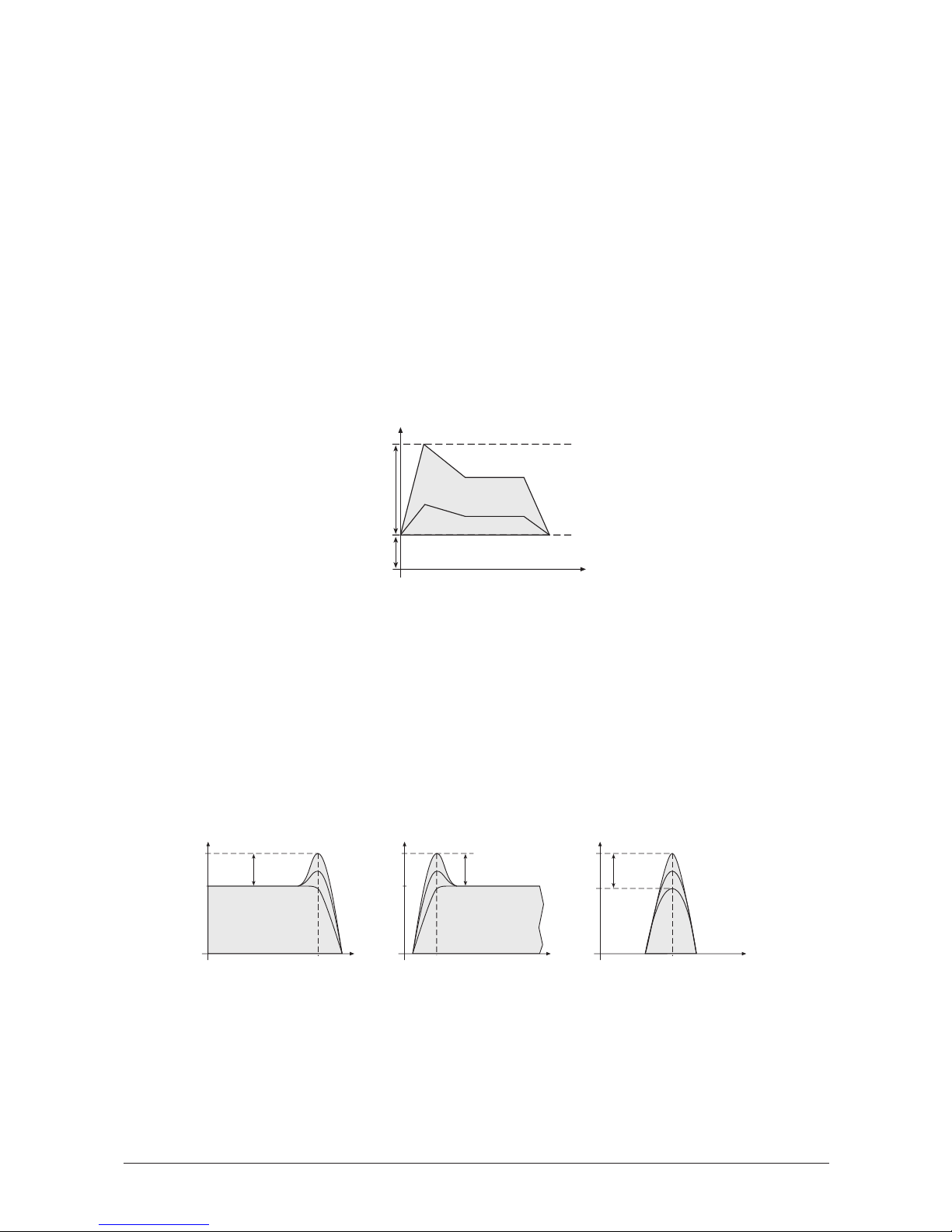
Cutoff Env. Amount
-64…+63
Determines the amount of influence the filter envelope has on the cutoff frequency. For
positive settings, the filter cutoff frequency is increased by the modulation of the envelope,
for negative settings, the cutoff frequency is decreased. Use this parameter to change the
timbre of the sound over time. Sounds with a hard attack usually have a positive envelope
amount that makes the start phase bright and then closes the filter to get a darker sustain
phase. On the other side string sounds usually use a negative envelope amount that gives a
slow and dark attack before the cutoff rises in the sustain phase.
Env. Velocity Amount
-64…+63
Determines the amount of influence the filter envelope has on the cutoff frequency, based
on key velocity. This parameter works similarly to the Cutoff Env. Amount parameter with
the difference that its strengh is velocity based. Use this feature to give a more expressive
character to the sound. When you hit the keys smoothly, only few modulation is applied.
When you hit them harder, the modulation amount also gets stronger. The following
diagram illustrates the functionality of this parameter:
The overall modulation applied to the filter’s cutoff frequency is calculated as the sum
of both parameters Cutoff Env. Amount and Env. Velocity Amount. Therefore you
should always bear in mind what the result is, especially when the filter does not
behave as you expect. You can also create interesting effects by setting one parameter
to a positive amount and the other to a negative.
Filter Types
This paragraph describes the MicroWave II/XT/XTk’s different filter types. Most types are
based on traditional low pass, high pass or band pass structures. The following diagram
illustrates the frequency plots of these types:
Frequency
Level
Cutoff
Resonance
Frequency
Level
Cutoff
Resonance
Low pass Band passHigh pass
Frequency
Level
Cutoff
Resonance
Velocity=40
Velocity=127
Velocity=1
Time
Cutoff
Frequency
Cutoff
Env.
Velocity
Amount
User’s Manual MicroWave II • MicroWave XT • XTk
53
Page 54

The filter types have the following display designations:
When some of the above types are selected, an extra parameter appears on the
Filter 1 / 2
page. Exactly what this parameter is for depends on the type of filter selected. The extra
parameter is therefore described together with every new filter type.
Modulation of the "Extra" Parameter
The "extra" parameter of the filter types described below may be selected in the modulation
matrix and is designated as
F1 Extra
. (An abbreviation of "Filter 1 Extra Parameter")
Do not mistake "FM Amount" for filter FM amount. The filter FM amount is the
F1 Extra
modulation destination whenever the FM-filter is selected on the
Filter 1 / 1
page. The
FM Amount
destination in the modulation matrix is for oscillator FM.
24db Low Pass and 12dB Low Pass
The low pass types
24dB LP
and
12dB LP
are suitable for the most usual applications. Use
the 24dB slope if you want to create sounds with a typical audible filtered character, use
the 12dB slope if you want to get softer results.
24db Band Pass and 12dB Band Pass
The band pass filters
24dB BP
and
12dB BP
remove frequencies both below and above the
cutoff point. As a result, the sound character gets narrow. Use these filter types for
programming effect and percussion-like sounds.
12db High Pass
The high pass filter
12dB HP
is useful to thin out a sound’s bass frequencies. This may give
interesting results also in conjunction with cutoff frequency modulation. By doing this you
can e.g. "fly-in" a sound starting at its high harmonics and then coming up to its full
frequency range.
Sine Waveshaper with 12dB Low Pass
The
Sin(x)>LP
Type consists of a sine waveshaper followed by a 12dB low pass filter with
resonance. The sine waveshaper usually adds some harmonics and intermodulation
frequencies to the signal.
Setting Filter Type
24dB LP
24dB low pass
12dB LP
12dB low pass
24dB BP
24dB band pass
12dB BP
12dB band pass
12dB HP
12dB high pass
Sin(x)>LP
Sine waveshaper followed by a 12dB low pass
WaveShapr
12dB low-pass filter with wave shaper
Dual L/BP
Parallel 12dB lowpass/bandpass filters
FM-Filter
12dB low-pass filter with frequency modulation
S&H>L12dB
Sample-and-hold in front of 12dB low-pass filter
24dBNotch
24dB notch filter
12dBNotch
12dB notch filter
Band Stop
Parallel 12dB low and high pass
54
User’s Manual MicroWave II • MicroWave XT • XTk
Page 55
12dB Low Pass followed by Wave Shaper
This new filter type consists of two components, the first being a normal 12dB low pass
filter as described in the user manual. The second component is a wave-shaper much like
the sine wave-shaping filter
Sin(x)>LP
also described in the manual. The difference between
the sine wave shaper and this new shaper is that the shaping wave is no longer a sine wave
but a wave from the wavetable used by the sound. Also, wave shaping is performed after
the filter in this case.
The extra parameter
Wave
, on the
Filter 1 / 2
page is used to select the desired shaping
wave from the sound’s wavetable (e.g. a triangle wave):
Filter 1 / 2
For a nice gritty sound, try a square wave as shaping wave! Nice for organ grinders.
12 dB parallel Low-pass and Band-pass Filters
This filter type consist of two filters parallel to each other. The first filter being of the lowpass type and the second of the band-pass type. As with the new wave shaping filter, the 12
dB low-pass filter can be adjusted the usual way as described in the user manual.
The band-pass filter’s cutoff frequency is the same as the cutoff frequency of the low-pass
filter cutoff setting except for the extra parameter
BP Offset
, which adds to the band-pass
filter’s cutoff frequency. The band-pass filter’s resonance is equal to that of the low-pass
filter.
Filter 1 / 2
To select a low-pass/band-pass with the latter set to one octave above the other, do the
following:
1. Go to the
Filter 1 / 1
page and select the
Dual L/BP
filter type.
2. Then go to the
Filter 1 / 2
page. The third parameter should now read
BP Offset
.
Change this setting so that it reads
+12
.
Because the BP offset is in semitones, the band-pass filter’s cutoff frequency is now an
octave above the low-pass filter’s cutoff frequency.
12 dB Low-pass Filter with Frequency Modulation
The FM-filter type is a 12dB low-pass filter where the cutoff frequency can be modulated by
the output of oscillator 2. The filter may be setup exactly like a normal low-pass filter as
described in the user manual.
The modulation amount
Osc2 FM
is the extra parameter and can be found on the
Filter 1 / 2
page:
Cutoff Env. Amount|Env.Velo| BP Offset
69 | -23 | +14
Cutoff Env. Amount|Env.Velo| Wave
69 | -23 | triangle
User’s Manual MicroWave II • MicroWave XT • XTk
55
Page 56
Filter 1 / 2
Sample-and-hold 12dB Low-pass Filter
The S&H-filter has a sample-and-hold (S&H) circuit with adjustable rate in front of the 12
dB low-pass filter. The S&H circuit effectively lowers the sampling rate so that the
harmonics are reflected to another frequency producing a harsh sound.
The rate of the S&H circuit is the extra parameter and appears on the
Filter 1 / 2
page as
S&H Rate
. When the S&H rate is set to maximum (127), the circuit passes the sound
untouched.
Filter 1 / 2
If you like nice clean sounds, the S&H filters are definitely not for you.
24dB Notch Filter
This filter damps a single frequency while all other frequency are passed through
unaffected. Resonance is inaudible on this filter type as long as its setting is not so high that
the filter begins to self-oscillate.
12dB Notch Filter
Same as 24dB notch filter, but lower slopes of 12dB/octave.
Bandstop Filter
This filter type uses a 12dB high pass and a 12dB low pass in parallel. By means of the
extra parameter Bandwidth the frequency of the high pass can be increased relative to the
low pass. If Bandwidth has a value of
0
, this filter is identical to the 12dB notch filter. The
resonance setting applies to both filters in the same way.
Filter 2
The second filter is capable of performing a low pass or high pass. The slope is always 6dB
per octave, there is no resonance parameter and therefore no self-oscillation. You can use
Filter 2 in several ways. Since its slope is more flat than those of Filter 1, the effect filtering
has on the sound is very subtle.
Filter 2
Cutoff
0…127
Determines the cutoff frequency. Note that you can also modulate the filter’s cutoff
frequency in the modulation matrix.
Type 6
dB LP / 6dB HP
Selects the filter type.
• Use the low pass setting
6dB LP
to get a warm sound without cutting of too much
of the higher frequencies.
Cutoff Filter 2 | Type |Keytrack
102 | 6dB LP | +000%
Cutoff Env. Amount|Env.Velo| S&H Rate
69 | -23 | 096
Cutoff Env. Amount|Env.Velo| Osc2 FM
69 | -23 | 078
56
User’s Manual MicroWave II • MicroWave XT • XTk
Page 57

• Use the high pass setting
6dB HP
to thin out the bass frequencies in order to get a
cleaner and more precious sound.
Keytrack
-200%…+197%
Determines how much the cutoff frequency depends on the MIDI note number. The
reference note for Keytrack is E3, note number 64. For positive settings, the cutoff frequency
rises on notes above the reference note, for negative settings the cutoff frequency falls up to
higher notes and vice versa. A setting of
+100%
corresponds to a 1:1 scale, so e.g. when
an octave is played on the keyboard the cutoff frequency changes for the same amount.
If you don’t want to use Filter 2, select the low pass and set the cutoff frequency to
127
.
User’s Manual MicroWave II • MicroWave XT • XTk
57
Page 58
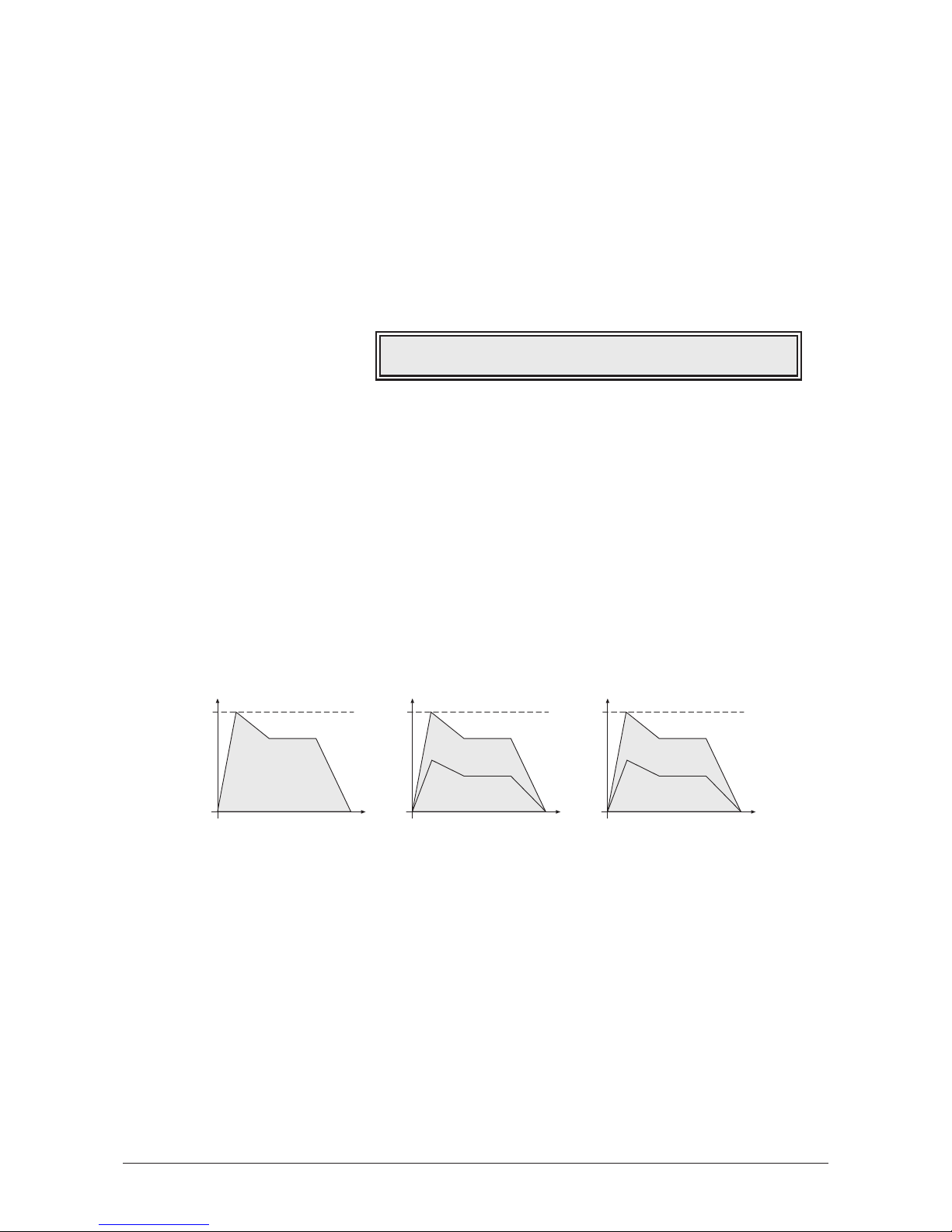
Volume and Pan
This unit is the last part in the MicroWave II/XT/XTk’s signal routing. Its purpose is to set the
volume and the pan position of the sound. After that the signal passes the D/A converter
and can be taken from the audio jacks on the rear panel.
To understand the operation of this unit, it is important to know that the Amplifier Envelope
is always acting as a modulation source for the volume. This means that an audio signal
can only pass through if the Amplifier Envelope is triggered and opened.
Finally a chorus effect can be added to enhance the sound.
Volume
Amplifier
Volume
0…127
Determines the master volume of the sound program.
Velocity
-64…+63
Specifies how much volume will be affected by keyboard velocity. Use this feature to give
more expression to the sound. With a setting of
0
, velocity will have no effect on the
volume. Classic organs work in this way because they do not have dynamic response. For
positive settings, the volume rises up to higher velocities. This is the most commonly used
setting which gives a piano-like character. For negative settings, the volume falls up to
higher velocities. This gives an untypical character suitable for effect sounds. As the
Amplifier always works in conjunction with the Amplifier Envelope, this parameter actually
determines the envelope velocity amount. The following diagram illustrates this
functionality:
Keytrack
-200%…+197%
Determines how much the volume depends on the MIDI note number. The reference note
for Keytrack is E3, note number 64. For positive settings, the volume increases on notes
above the reference note, for negative settings the volume decreases up to higher notes and
vice versa. This setting can be useful to adjust a sound’s volume over the whole keyboard
range. Especially when extensive filtering is used, the sound can be louder on the lower or
the upper part of the keyboard. On the other side, you can apply this effect intentionally
e.g. for effect sounds.
Key velocity=64
Key velocity=127
Key velocity=1
Maximum volume
Velocity parameter = +63
Time
Volume
Key velocity=1…127
Maximum volume
Velocity parameter = 0
Time
Volume
Key velocity=64
Key velocity=1
Key velocity=127
Maximum volume
Velocity parameter = -64
Time
Volume
Volume |Velocity |Keytrack | Chorus
090 | +40 | +000% | on
58
User’s Manual MicroWave II • MicroWave XT • XTk
Page 59
Chorus
off / on
Enables the chorus effect. The chorus consists of two short delays where delay time is
modulated with a sine wave of about 0.5 Hz. It spreads the stereo image of the program by
giving it a wide sounding character.
Pan
Pan
Panning
left 64…center…right 63
Determines the position in the stereo panorama. When the setting is
left 64
, the sound is
panned far left, when the setting is
right 63
, it is panned far right. If you want to set the
sound into the middle of the stereo panorama, use the
center
setting. To give further
movement to the sound, set this parameter to a basic value and apply some modulation to
it e.g. via an LFO or the Keytrack parameter.
Keytrack
-200%…+197%
Determines how much the pan position depends on the MIDI note number. The reference
note for Keytrack is E3, note number 64. For positive settings, the panning moves to the
right on notes above the reference note, for negative settings the panning moves to the left
up to higher notes and vice versa. This feature enables you to give a typical piano-like
panning, where lower notes are on the left side and higher notes on the right. To achieve
this, set the Panning parameter to
center
and Keytrack to
+197
.
Panning |Keytrack
left 50| +020%
User’s Manual MicroWave II • MicroWave XT • XTk
59
Page 60
Effects
The Microwave II and Microwave XT have the ability to change the timbre of a sound by
way of effects processing. In the table below the types of effects are shown together with
the availability for the two types of Microwave.
All the effect parameters are available on the
Effect
page which is located between the
Amplifier
and
Pan
page. The first parameter on the
Effect
page is always the effect type
parameter. The other three parameters change according to the type of effect which has
been selected.
Please note that only Instruments 1…3 of a Multi program can use effects.
Some Words about Effects
It is very difficult to describe effects such as chorus and flanger. Therefore, the description
of the exact timbre changes induced by the effects has been omitted. As it would serve no
purpose to clutter the manual with subjective obscurity. Just have a play with the effects!
The Mix Parameter
Most of the effects have a mix parameter. This parameter determines the volume ratio
between the original signal and the effect output. To further stress the fact that this is a ratio,
the mix parameter is display as two numbers. The first number is the original or dry signal
amount. The second number is the effect’s output amount, or wet signal amount. The two
numbers are separated by a colon (see chorus display example).
Chorus
Below, the display of the Microwave is shown with the Chorus effect selected:
Effect
Speed
0…127
Determines the oscillator speed of the chorus effect.
Depth
0…127
Determines the amount of the chorus.
Mix
127:0…0:127
Determines the volume ratio of the dry and wet signal.
Effect | Speed | Depth | Mix
Chorus | 052 | 048 | 0:127
MicroWave II MicroWave XT
Chorus Chorus
Flanger 1 Flanger 1
Flanger 2 Flanger 2
AutoWahLP AutoWahLP
AutoWahBP AutoWahBP
Overdrive Overdrive
Amp. Mod Amp. Mod
Delay
Pan Delay
Mod Delay
60
User’s Manual MicroWave II • MicroWave XT • XTk
Page 61
Flanger 1
Effect
Speed
0…127
Determines the oscillator speed of the flanger effect.
Depth
0…127
Determines the amount of flanging.
Mix
127:0…0:127
Determines the volume ratio of the dry and wet signal.
Flanger 2
Effect
Speed
0…127
Determines the oscillator speed of the flanger effect.
Feedback
0…127
Determines the amount of feedback.
Mix
127:0…0:127
Determines the volume ratio of the dry and wet signal.
AutoWahLP
Effect
The AutoWahLP is basically a low-pass filter of which the cutoff is determined by the
signal’s strength.
Sense
0…127
Controls the filter’s sensitivity according to the signal’s strength.
Cutoff
0…127
The minimal cutoff frequency of the filter.
Resonance
0…127
Filter resonance.
Effect | Sense | Cutoff |Resonance
AutoWahLP| 065 | 038 | 010
Effect | Speed |Feedback | Mix
Flanger 1| 038 | 100 | 55:72
Effect | Speed | Depth | Mix
Flanger 1| 052 | 048 | 0:127
User’s Manual MicroWave II • MicroWave XT • XTk
61
Page 62
AutoWahBP
Effect
The AutoWahBP is basically a band-pass filter of which the cutoff is determined by the
signal’s strength.
Sense
0…127
Controls the filter’s sensitivity according to the signal’s strength.
Cutoff
0…127
The minimal cutoff frequency of the filter.
Resonance
0…127
Filter resonance.
Overdrive
Effect
Drive
0…127
Determines how much distortion is applied.
Gain
0…127
Determines the output volume of the distortion.
Amp Type
0…127
Allows one to select the speaker simulation setting. These settings are available:
Setting Type of Simulation
Direct
No speaker simulation
Combo
Simulation of a small speaker with
small bandwidth
Medium
Simulation of a larger speaker with
medium bandwidth
Stack
Simulation of an array of speakers
with large bandwidth
Effect | Drive | Gain |Amp Type
Overdrive| 018 | 093 | Combo
Effect | Sense | Cutoff |Resonance
AutoWahBP| 065 | 038 | 010
62
User’s Manual MicroWave II • MicroWave XT • XTk
Page 63
Amp. Mod
Effect
The Amplitude Modulator can be used as a tremolo or as a low-frequency ring modulator.
For use as a tremolo, the dry signal (the first number of the Mix parameter) must be kept
above
63
. For use as a ring modulator, the dry signal must be kept below 64.
Speed
0…127
Oscillator speed of the amplitude modulator.
Spread
0…127
Amount of lag between the left and right channel.
Mix
127:0…0:127
Determines the volume ratio of the dry and wet signal.
Delay
Effect
Time
Delay time. This parameter is displayed as a note type followed by a Beats-Per-Minute
number. So
1/4 [74]
means that the delay time is a quarter-note at 74 BPM.
Feedback
0…127
Determines the amount of delayed signal being fed back into the delay.
Mix
127:0…0:127
Determines the volume ratio of the dry and wet signal.
Pan Delay
Effect
The only difference between Delay and Pan Delay is that the delayed signal seems to
bounce from the left channel to the right and back again.
Effect | Time |Feedback | Mix
Pan Delay|1/4 [74]| 090 | 106:21
Effect | Time |Feedback | Mix
Delay |1/4 [74]| 090 | 106:21
Effect | Speed | Spread | Mix
Amp. Mod | 038 | 100 | 55:72
User’s Manual MicroWave II • MicroWave XT • XTk
63
Page 64
Mod Delay
Effect
The modulated delay is a delay type effect where the delay time is modulated by a low
frequency oscillator. The speed of the oscillator and the amount of change caused by the
oscillator are parameters of this effect.
Time
Delay time. This parameter is displayed as a note type followed by a Beats-Per-Minute
number. So
1/4 [74]
means that the delay time is a quarter-note at 74 BPM.
Speed
0…127
The speed of the modulating oscillator.
Depth
0…127
Amount of change in the delay time caused by the oscillator.
Effect | Time | Speed | Depth
Mod Delay|1/4 [74]| 010 | 108
64
User’s Manual MicroWave II • MicroWave XT • XTk
Page 65
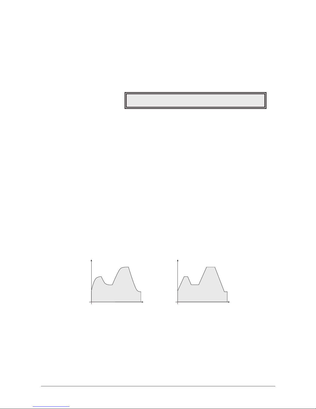
Portamento and Glissando
The term "portamento" describes the continuous gliding from one note to the next like
strings or some brass instruments (e.g. trombone) can do. A glissando is a similar effect with
one difference: The pitch does not change continuously but in note steps. On acoustic
instruments a glissando can be performed e.g. on a piano when you play very fast over a
wide key range. The MicroWave II/XT/XTk offers some different effect types that can be
trimmed for each situation. The term "glide" is used for all different types of effect in
common.
Glide
Active
off / on
Enables or disables the glide effect.
Type
porta / glissando / fingered / f.gliss
Determines the effect type.
•
Porta
selects a normal portamento effect with all notes gliding continously from
one to the next.
• Similar to that,
gliss
selects the normal glissando effect with all notes gliding in
semitone steps.
• When
fingered
or
f.gliss
is selected, the portamento or glissando is only applied on
legato played notes and so the first note played is not influenced. This feature is
useful especially for solo sounds, when it is often undesireable to slide into the
beginning.
Mode
exp. / linear
Selects whether the pitch is changed in an
exponential
or
linear
style. On classic analog
synthesizer the
exponential
style was used mainly since it could be easily created with
analog circuits. The
linear
setting produces a more accurate gliding with better audible
results. The following diagram illustrates the difference between the two modes:
Time
0…127
Determines the glide time. Low values will give a short glide time in the range of
milliseconds that gives a special character to the sound. High values will result in a long
glide time up to several seconds which can be useful for solo and effect sounds.
exponential linear
Time
Pitch
Time
Pitch
Active | Type | Mode | Time
on | Gliss | exp. | 25
User’s Manual MicroWave II • MicroWave XT • XTk
65
Page 66
Trigger
The Trigger parameters define how the various envelopes are started. In addition, you can
activate special dual and unisono modes to stack the MicroWave II/XT/XTk’s voices.
Trigger 1
Trigger 2
FilterEnv
normal / single / retrigger
Determines the way of triggering the Filter Envelope.
• If
normal
is selected, every note triggers the envelope of its own voice.
• If
single
is selected, the envelopes of all voices act as one. The envelope is started,
when the first note is played. The sustain phase is held until the last note is
released. Then the release phase is performed.
• If
retrigger
is selected, the envelope acts as in single mode except that each note
triggers the envelope again from its current value.
Amp. Env
normal / single / retrigger
Determines the way of triggering the Amplifier Envelope.
• If
normal
is selected, every note triggers the envelope of its own voice.
• If
single
is selected, the envelopes of all voices act as one. The envelope is started,
when the first note is played. The sustain phase is held until the last note is
released. Then the release phase is performed. This setting is only valid, if Mode is
set to
Mono
. Otherwise the envelope works as if
normal
is selected.
• If
retrigger
is selected, the envelope acts as in single mode except that each note
triggers the envelope again from its current value. This setting is only valid, if Mode
is set to
Mono
. Otherwise the envelope works as if
normal
is selected.
Wave Env.
normal / single / retrigger
Determines the way of triggering the Wave Envelope.
• If
normal
is selected, every note triggers the envelope of its own voice.
• If
single
is selected, the envelopes of all voices act as one. The envelope is started,
when the first note is played. The sustain phase is held until the last note is
released. Then the Key-off phase is performed.
• If
retrigger
is selected, the envelope acts as in single mode except that each note
triggers the envelope again from its current value.
Mode | Assign | Detune | De-Pan
Poly |unisono | 025 | 110
FilterEnv|Amp. Env |Wave Env.|Free Env.
normal | single | normal |retrigger
66
User’s Manual MicroWave II • MicroWave XT • XTk
Page 67

Free Env.
normal / single / retrigger
Determines the way of triggering the Free Envelope.
• If
normal
is selected, every note triggers the envelope of its own voice.
• If
single
is selected, the envelopes of all voices act as one. The envelope is started,
when the first note is played. The sustain phase is held until the last note is
released. Then the release phase is performed.
• If
retrigger
is selected, the envelope acts as in single mode except that each note
triggers the envelope again from its current value.
Mode
Poly / Mono
Selects whether the sound can be played polyphonic or monophonic.
• Use the
Poly
setting for normal applications when you where to play chords.
• If
Mono
is selected, the MicroWave II/XT/XTk playes only the last incoming note.
Use this mode for solo sounds, especially in combination with the Glide effect.
Assign
normal / dual / unisono
Defines who the sound’s voices are assigned to the played notes.
• If
normal
is selected, every played note uses one of the MicroWave II/XT/XTk’s
voices.
• If
dual
is selected, every note uses two voices which can be detuned by the
Detune parameter described below.
• If
unisono
is selected, all voices are used, divided to the notes played. That means,
if you play just one note, all 10 voices of the MicroWave II/XT/XTk are used for this
note. If you play two notes, 5 voices are used for each note and so on. The Detune
parameter is also active in this mode.
Detune
0…127
Determines the amount of oscillator detune when
dual
or
unisono
is selected in the
Assign parameter. The setting always represents the maximum detune range of all used
voices. E.g. in dual mode a value of
40
means a detune of
-20
for the first voice and
+20
for the second.
De-Pan
0…127
If
dual
or
unisono
is selected, the voices are spread in panorama according to this
parameter. Use
127
to get a full spread or 0to get no spread at all. If neither
dual
nor
unisono
is selected, the setting of this parameter has no audible effect.
User’s Manual MicroWave II • MicroWave XT • XTk
67
Page 68
Arpeggiator
An arpeggiator is a device that splits an incoming MIDI chord into its single notes and
repeats them rhythmically. Different sequence modes can be defined for the arpeggiator to
cover a wide range of applications.
In addition to the synthesis features, the MicroWave II/XT/XTk offers a separately
programmable arpeggiator for every sound program. The arpeggiator can be used
independently or synced to MIDI clock. It can play a wide range of different rhythm
patterns, including a user programmable.
The arpeggiator uses an internal buffer that can store up to 20 notes. The buffer is cleared
each time a new chord is played. There are two ways of entering a chord:
• Press all keys of the chord simultaniously.
• Press and hold the first key of the chord. While holding this key, enter the other
keys sequentially. After playing all keys, release the first key again. On one hand
this method is practicable for playing difficult chords, on the other hand it is
essential when using the
as played
setting of the Direction parameter. This setting
allows you to create arpeggios in the sequence of played notes.
When you use the sound as part of a multi program, you can either use the sound’s
arpeggiator described here, or the dedicated arpeggiator of the multi program’s
instrument. Use the instrument parameter Arpeggiator Active to select which one to
use. As a default the sound’s arpeggiator is not activated and therefore no arpeggio
will be generated when turning on the arpeggiator here.
Arpeggiator 1
Arpeggiator 2
Arpeggiator 3
Arpeggiator User Pattern
Active
off / on / hold
Enables or disables the arpeggiator or activates the
hold
mode. When
hold
is activated,
incoming MIDI chords generate continuous arpeggios even when the chord is released. The
MicroWave II/XT/XTk will continue to do so until you play a new chord or this parameter is
set back to
off
or on. You can also stop the arpeggiator by performing the panic function or
sending an All Notes Off message from your sequencer.
Position | Trigger
03 | on [*-*--**-]
Reset on Pattern Start | Length
off | 08
Pattern |Direction|NoteOrder|Velocity
on |alternate|as played|last note
Active | Tempo | Clock | Range
on | 126 | 1/16 | 04
68
User’s Manual MicroWave II • MicroWave XT • XTk
Page 69
Tempo
extern / 50…300
Sets the arpeggiator’s basic tempo. Can be defined manually in BPM (beats per minute) or
via MIDI clock, if
extern
is selected.
The arpeggiator can be used as a master as well as a slave via the MIDI clock:
• When you use the arpeggiator as the master, set its speed via the Tempo parameter.
Set the global parameter MIDI Clock Send to
on
. This enables the sending of MIDI
clock signal via the MicroWave II/XT/XTk’s MIDI out jack 쐊.
• When you use the arpeggiator as a slave, an external device (e.g.sequencer)
determines the tempo of the arpeggiator. Set the Tempo parameter to
external
as
described above. Here, too, notes and MIDI clock information can be used to
control other devices. In this mode, the MIDI Song Position Pointer is also
recognized.
Clock
1/1…1/32
Determines the note value for whole notes to thirty-second notes. The basis is a 4/4 beat.
Triplets (e.g.
1/8T
) and dotted notes (e.g.
1/16.
) are available for every value.
Range
1…10
Determines the range of the single notes in octaves.
Pattern
off / user / 1…15
Determines whether an rhythm pattern is played and which one.
• If
off
is selected, the arpeggiator playes its notes in regular steps, specified by the
Clock parameter.
• If
user
is selected, the arpeggiator uses the free programmable pattern defined in
the
Arpeggiator User Pattern
page.
• Additionally, the arpeggiator features 15 preset rhythm patterns. These are
numbered from
1
through 15. Here is an overview of the arpeggiator preset
patterns:
Diagram 4: Arpeggiator patterns
● ●●● ●●● ●●● ●●
●●● ●●●● ●
●●●●●●●●●●
● ●●● ● ● ●●● ●
●●●●●●●●●●
●●●●●●●●●●
●●●●●●●●●
●●●●●●●●●
●●● ●●● ●●● ●●●
●● ●● ●● ●● ●●●
●● ●● ●● ●● ● ●
●●●●●●●●●●
●●●●●●●●●●
●●●●●●
●●●●● ●●●
1
2
3
4
5
6
7
8
9
10
11
12
13
14
15
Pattern 1 2 3 4 5 678910111213141516
User’s Manual MicroWave II • MicroWave XT • XTk
69
Page 70

Direction
up / down / alternate / random
Determines the sequence of generated notes according to pitch.
• If
up
is selected, the arpeggio starts at the lowest note and sweeps up through the
notes until it reaches the highest note. It then starts at the bottom again.
• If
down
is selected, the arpeggio starts at the highest note and sweeps down
through the notes until it reaches the lowest note. It then starts at the top again.
• If
alternate
is selected, the arpeggio starts at the lowest note and sweeps up through
the notes until it reaches the highest note. It then starts to sweep back down.
• If
random
is selected, the arpeggio plays any of the notes in a random order.
NoteOrder
by note / note rev. / as played / reversed
Determines the sequence of generated notes according to note order.
• If
by note
is selected, the arpeggio sequence is sorted by the MIDI note number.
This is the standard mode, used by most arpeggiators.
• If
note rev.
is selected, the arpeggio sequence is sorted in the exactly reversed
order to the
by note
setting.
• If
as played
is selected, the arpeggio is generated in the order of the incoming
notes. In combination with the user programmable pattern this feature offers a
small but effective step sequencer.
• If
reversed
is selected, the arpeggio is generated in the reverse order of the
incoming notes.
To understand the difference of the individual settings, it is nessessary to "step-input" the
notes of the chord as described at the beginning of this chapter.
Velocity
root note / last note
Determines how the velocity values of the generated notes are calculated.
• If
root note
is selected, every generated note inherits its velocity from its base note.
E.g. if the base chord for the arpeggio contains an E with a certain velocity, all
generated E notes also have this velocity value, independent of their octave setting.
• If
last note
is selected, every generated note has the same velocity as the last
incoming note.
Reset on Pattern Start
off / on
Selects if the arpeggiator is reset each time the rhythm pattern starts again. If the setting is
disabled, the arpeggiator plays all chord notes from the first to the last and over again,
regarding the sequence determined by Direction and Note Order. If the setting is enabled,
the arpeggiator only plays the number of chord notes that correspond to the pattern length.
Then it starts with the first chord note at its basic octave again. The result is similar to
pressing the chord again each time the pattern restarts. If no pattern is selected, this
parameter has no function.
Length
1…16
Determines the length of the user programmable rhythm pattern.
70
User’s Manual MicroWave II • MicroWave XT • XTk
Page 71
Position
1…pattern length
Trigger
off / on
These two parameters are used to define the user programmable rhythm pattern. Before
entering the pattern, you must set its length via the Length parameter. Use the Position
parameter to select the position of the pattern you want to edit. Then use the Trigger
parameter to define the state of the selected position. All active positions are marked with a
"*" in the display, all inactive positions show a "-". Note that you can also create triplet
rhythms by setting the pattern length to 3, 6 or 12 and selecting a triplet value for the
Clock parameter.
Arpeggiator User Pattern
Position | Trigger
03 | on [*-*--**-]
User’s Manual MicroWave II • MicroWave XT • XTk
71
Page 72
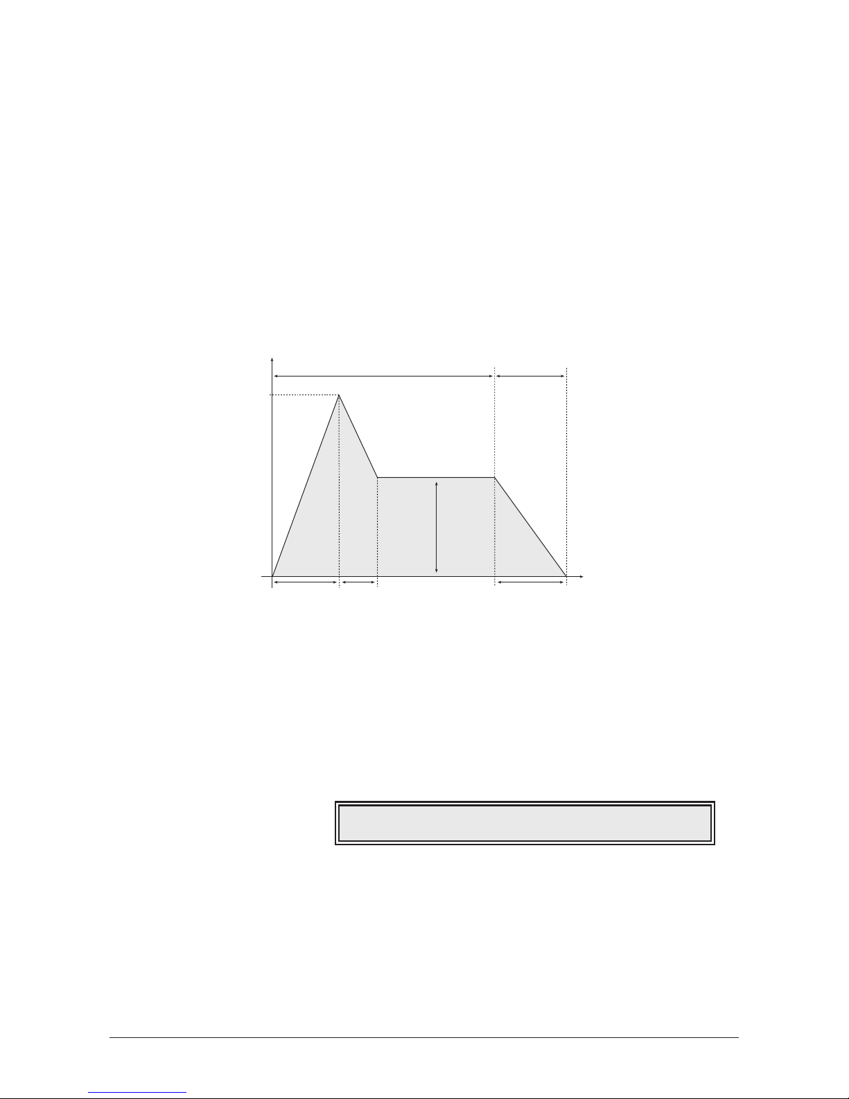
Envelopes
The MicroWave II/XT/XTk’s envelopes allow you to manipulate sound parameters via rate
or timed modulations. The MicroWave II/XT/XTk offers four independent programmable
envelopes for every sound program:
• A filter envelope with ADSR characteristic
• A volume envelope with ADSR characteristic
• A wave envelope with 8 different times and levels (multi segment envelope)
• An additional free multi segment envelope with 3 different times and levels and a
release time and release level
Most traditional synthesizers feature ADSR envelopes. These envelopes are made up
of four parameters that determine their response: Attack, Decay, Sustain and
Release. The following diagram illustrates the structure of an ADSR envelope:
The envelope is started by pressing a key. It ascends to its maximum value at the rate
determined by the Attack parameter. It then descends at the rate determined by the
Decay value until it reaches the predetermined Sustain value. It remains at this
value until the key is released. The envelope then descends to zero at the rate
determined by the Release parameter.
Filter Envelope
This envelope is designed to control the filter but can also be used for other modulations.
The following parameters determine the envelope’s response.
Filter Env
Attack
0…127
Determines the attack rate or amount of time it takes for a signal to go from zero to
maximum level.
Decay
0…127
Determines the decay rate or amount of time it takes for a signal to reach the Sustain
level.
FE Attack| Decay | Sustain | Release
000 | 035 | 090 | 020
Attack Decay Release
Sustain
Depth
Time
Key pressed Key released
100%
72
User’s Manual MicroWave II • MicroWave XT • XTk
Page 73
Sustain
0…127
Determines the sustain level which is held until a note ends.
Release
0…127
Once the note has ended, the release phase begins. During this phase, the envelope fades
to zero at the rate determined by the Release value.
Amplifier Envelope
This envelope is designed to control the sound volume, but can also be used for other
modulations. The following parameters determine the envelope’s response.
Amplifier Env
Attack
0…127
Determines the attack rate or amount of time it takes for a signal to go from zero to
maximum level.
Decay
0…127
Determines the decay rate or amount of time it takes for a signal to reach the Sustain
level.
Sustain
0…127
Determines the sustain level which is held until a note ends.
Release
0…127
Once the note has ended, the release phase begins. During this phase, the envelope fades
to zero at the rate determined by the Release value.
AE Attack| Decay | Sustain | Release
000 | 035 | 090 | 020
User’s Manual MicroWave II • MicroWave XT • XTk
73
Page 74

Wave Envelope
The MicroWave II/XT/XTk’s wave envelope features a multi segment characteristic with 8
separately adjustable times and levels.
Multi segment envelopes are extremely flexible modulation sources. Their structure is
made of grouped time/level parameters that allows one to generate an almost free
modulation amount over several time segments. The following diagram illustrates the
structure of a multi segment envelope:
As shown in the diagram, the envelope consists of several single segments. Also the
figure can be divided into a sustain and a release phase. The crossover point between
these two phases can be determined by selecting the corresponding segment number.
The envelope is started by pressing a key. It ascends to the Level 1 value at the rate
determined by the Time 1 parameter. In the next time segment Time 2 the amplitude
moves to the Level 2 value. The same procedure is processed for the following
segments until the end of the sustain phase is reached. In the shown example Level 6
is the last value of the sustain phase. The amplitude remains at this value until the key
is released. The envelope then moves on to process the remaining segments until it
finally ends with its last value Level 8. In fact you can reduce the number of
processed segments to get things easier. Additionally you can repeat specific
segments by installing loops in the sustain phase as well as in the release phase.
Wave Env / 1…4
Wave Env / 5
Wave Env / 6
Time 1…8
0…127
Determines the time for the individual segment to reach its end level.
Key Off Loop |Loop Start|Loop End
||
Key On Loop |Loop Start|Loop End
||
Time 1 | Level 1 | Time 2 | Level 2
020 | 100 | 115 | 063
Time 1 Time 2 Time 8
Level
Time
Key pressed Key released
Time 4 Time 5 Time 6Ti.3 Time 7
Level 1
Level 2
Level 3
Level 4
Level 5
Level 6
Lev.7
Level 8
74
User’s Manual MicroWave II • MicroWave XT • XTk
Page 75

Level 1…8
0…127
End level that the corresponding segment finally reaches.
Key On Loop
off / on
Selects whether a loop is performed in the envelope’s sustain phase or not.
Loop Start
1…8
Defines the starting point for the sustain loop if Key On Loop is enabled.
Loop End
1…8
Defines the ending point for the sustain loop if Key On Loop is enabled. It further
determines the end of the sustain phase and the beginning of the release phase. Note that
this feature is also valid when Key On Loop is disabled.
Key Off Loop
off / on
Selects whether a loop is performed in the envelope’s release phase or not.
Loop Start
1…8
Defines the starting point for the release loop if Key Off Loop is enabled.
Loop End
1…8
Defines the ending point for the release loop if Key Off Loop is enabled. It further
determines the last segment of the whole envelope. No segment beyond the selected
number will be used. Note that this feature is also valid when Key Off Loop is disabled.
The loop points are numbered from 1 to 8. Each number represents the end of the
corresponding segment, e.g. no. 3 means the point of Level 3 after Time 3. As you
can see, the first loop point is at the end of segment 1. Therefore segment 1 can not
be looped.
The following examples illustrate the use of the Wave Envelope:
☞ This is how you setup an classic ADSR-like envelope:
1. Set Key On Loop and Key Off Loop to
off
. This ensures that no loops are
performed.
2. Set Level 1 to
127
.
3. Specify the Attack time via the Time 1 parameter.
4. Specity the Decay time via Time 2.
5. Use Level 2 to setup the Sustain level.
6. Set Key On Loop Start to
1
and Key On Loop End to 2. This specifies segment
2 of the envelope as last segment in the sustain phase.
7. Set Level 3 to
0
.
8. Specify the Release time via Time 3 .
9. Set Key Off Loop End to
3
. This causes the envelope to stop after segment 3.
User’s Manual MicroWave II • MicroWave XT • XTk
75
Page 76
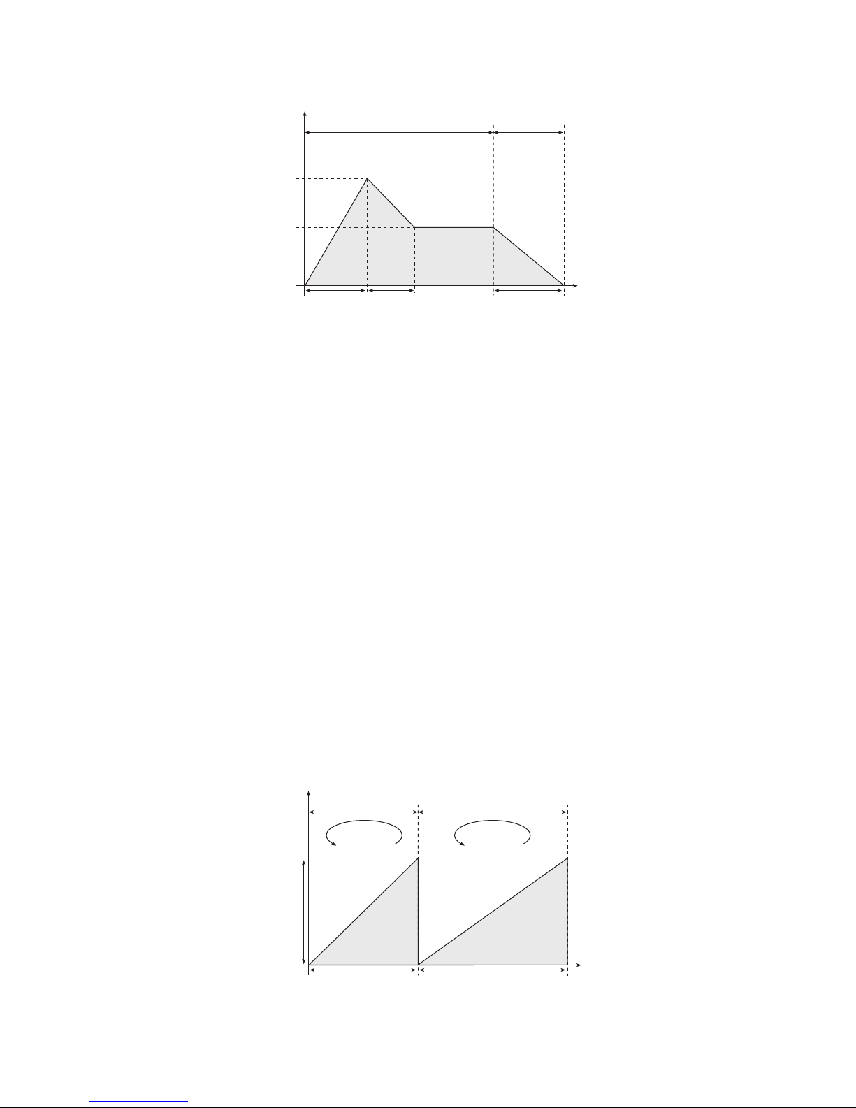
The following diagram shows how this example works:
☞ This is how you setup an envelope that it works like a sawtooth LFO with different
rates in the sustain and release phase:
1. Set Key On Loop and Key Off Loop to on. This causes both loops in the sustain
and in the release phase to be activated.
2. Set Level 1 and Time 1 to
0
. This deactivates segment 1 because it can not be
looped.
3. Set Level 2 to
127
. This defines the maximum value of the sawtooth’s amplitude.
4. Specify the rate of the sawtooth for the sustain phase via the Time 2 parameter.
5. Set Key On Loop Start to
1
and Key On Loop End to 2. This will repeat
segment 2 of the envelope as long as the key is pressed.
6. Set Level 3 to
0
. This defines the minimum setting of the sawtooth’s amplitude.
7. Set Time 3 to
0
. This causes the envelope abruptly to minimum level after
releasing the key and sets the minimum value of the sawtooth’s amplitude in the
release phase.
8. Set Level 4 to
127
. This defines the maximum value of the sawtooth’s amplitude
in the release phase.
9. Specify the rate of the sawtooth for the release phase via the Time 4 parameter.
10. Set Key Off Loop Start to
3
and Key Off Loop End to 4. This will repeat
segment 4 of the envelope in the release phase.
The following diagram shows how this example works:
Time 1 = 0
Level 1 = 0
Time 2
Level
Time
Key pressed Key released
Time 4
Time 3 = 0
Level 3 = 0
Level 2 = 127
Level 4 = 127
1
2
3
4
Key On Loop Start = 1
Key On Loop End = 2
Key Off Loop Start = 3
Key Off Loop End = 4
Time 1
Level
Time
Key pressed Key released
Time 2
Level 1 = 127
1
3
Key On Loop End = 2 Key Off Loop End = 3
2
Time 3
Level 2
Level 3 = 0
76
User’s Manual MicroWave II • MicroWave XT • XTk
Page 77
Free Envelope
In addition to the previously described envelopes, the MicroWave II/XT/XTk offers a Free
Envelope which can be used for modulation purposes. This envelope also features a multi
segment structure. It consists of 4 segments and has no loop functionality. The first 3
segments always belong to the sustain phase, the last one always belongs to the release
phase. The main difference to the other envelopes is that the Free Envelope features bipolar
levels. Therefore it can generate modulation amounts in the range -1…0…+1.
Free Env / 1
Free Env / 2
Time 1…3
0…127
Determines the time for the individual segment to reach its end level.
Level 1…3
-64…+63
End level that the corresponding segment finally reaches.
Release
0…127
Determines the length of the release phase when the key is released. The envelope then
descends to the R. Level.
R. Level
-64…+63
Last level that is reached when the release phase ends.
Time 3 | Level 3 | Release |R. Level
095 | 070 | 064 | 025
Time 1 | Level 1 | Time 2 | Level 2
020 | 100 | 115 | 063
User’s Manual MicroWave II • MicroWave XT • XTk
77
Page 78
Low-frequency Oscillators (LFOs)
In addition to the main oscillators, the MicroWave II/XT/XTk is equipped with two lowfrequency oscillators which can be used for modulation purposes. Each LFO generates a
periodic waveform with adjustable frequency and shape.
LFO 1
LFO 1 / 1
LFO 1 / 2
Rate
0…127 (128 Bars…1/64)
Determines the frequency of the generated signal. If Sync is set to
Clock
, the value is
shown in musical notation. The basis is a 4/4 beat. Triplets (e.g.
1/8T
) and dotted notes (e.g.
1/16.
) are available for some values.
Shape
sine / triangle / square / sawtooth / random / S & H
Determines the type of waveshape to be generated. Sample & Hold samples a random
value and holds it until the next LFO cycle begins. If Rate has a value of
0
, then a random
value is generated for each new incoming MIDI note. More variations can be achieved by
means of the Symmetry parameter. Please read the corresponding paragraph later on in
this chapter.
Delay
off / retrigger / 1…126
Determines the start of the LFO cycle after an incoming MIDI note.
• If
off
is selected, the LFO runs completely free, which means its cycle is not
synchronised to the note start. Use this setting e.g. when modulating the filter
cutoff of a sound that should be different each time you play it.
• If
retrigger
is selected, the LFO starts its cycle after receiving a note. This is also
known as "key sync" feature. This setting is useful when the LFO must always start
at a fixed value, e.g. when creating an alert sound.
• If
1…126
is selected, the LFO is works like in
retrigger
mode, but is delayed with
the specified amount. This setting is useful e.g. for solo sounds with a vibrato or
tremolo that is only applied on long notes.
Sync
off / on / Clock
Selects if the LFO is synchronised. If
off
is selected, the LFO runs completely independent.
If
on
is selected, all LFOs of the MicroWave’s voices used by the sound program behave as
one. If
Clock
is selected, the LFO is synchronised to an incoming MIDI Clock signal.
Symmetry |Humanize
+27 | 003
Rate | Shape | Delay | Sync
028 |triangle | 005 | off
78
User’s Manual MicroWave II • MicroWave XT • XTk
Page 79
Symmetry
-64…+63
Adjusts the relationship between the rising and the falling edge of the signal. When set to 0
the generated waveshape is symmetrical. When set to positive values, the positive cycle
becomes longer and the negative cycle becomes shorter and vice versa. Use this parameter
to change to pulsewidth of the square signal. When using it on a triangle waveshape, you
can get a sawtooth wave with a soft rising or falling slope. The following diagram illustrates
this effect:
Humanize
off / 1…127
Allows one to add a random variation to the LFO speed. When disabled, the LFO remains
at its initial speed, preset by the Rate parameter. Low settings add a human touch to the
sound, high settings are useful when creating effect sounds with an irregular character e.g a
wind sound where the filter frequency is modulated by an LFO. The following diagram
shows the effect of the Humanize setting:
LFO 2
The second LFO offers the same functionality as the first one. In addition it can be linked
with LFO 1.
LFO 2 / 1
LFO 2 / 2
Rate
0…127
Determines the frequency of the generated signal.
Symmetry |Humanize | Phase
+27 | 003 | 090
Rate | Shape | Delay | Sync
028 |triangle | 005 | off
Humanize = off Humanize = 127
Time
Level
Time
Level
Symmetry = 0 Symmetry = +40 Symmetry = -40
Time
Level
Time
Level
Time
Level
User’s Manual MicroWave II • MicroWave XT • XTk
79
Page 80

Shape
sine / triangle / square / sawtooth / random / S & H
Determines the type of waveshape to be generated. Sample & Hold samples a random
value and holds it until the next LFO cycle begins. If Rate has a value of
0
, then a random
value is generated for each new incoming MIDI note. More variations can be achieved by
means of the Symmetry parameter. Please read the corresponding paragraph later on in
this chapter.
Delay
off / retrigger / 1…126
Determines the start of the LFO cycle after an incoming MIDI note.
• If
off
is selected, the LFO runs completely free, which means its cycle is not
synchronised to the note start. Use this setting e.g. when modulating the filter
cutoff of a sound that should be different each time you play it.
• If
retrigger
is selected, the LFO starts its cycle after receiving a note. This is also
known as "key sync" feature. This setting is useful when the LFO must always start
at a fixed value, e.g. when creating an alert sound.
• If
1…126
is selected, the LFO is works like in
retrigger
mode, but is delayed with
the specified amount. This setting is useful e.g. for solo sounds with a vibrato or
tremolo that is only applied on long notes.
Sync
off / on
Selects if the LFO is synchronised. If
off
is selected, the LFO runs completely independent.
If
on
is selected, all LFOs of the MicroWave’s voices used by the sound program behave as
one.
Symmetry
-64…+63
Adjusts the relationship between the rising and the falling edge of the signal. When set to 0
the generated waveshape is symmetrical. When set to positive values, the positive cycle
becomes longer and the negative cycle becomes shorter and vice versa. Use this parameter
to change to pulsewidth of the square signal. When using it on a triangle waveshape, you
can get a sawtooth wave with a soft rising or falling slope. Please refer to the description of
LFO 1 to get further information.
Humanize
off / 1…127
Allows one to add a random variation to the LFO speed. When disabled, the LFO remains
at its initial speed, preset by the Rate parameter. Please refer to the description of LFO 1 to
get further information.
Phase
off / 3…357
If disabled, LFO 2 operates independently from LFO 1. If enabled, the frequency of the
generated signal is determined by LFO 1. The Phase parameter defines the angle in degrees
from which LFO 2’s signal is phase shifted to LFO 1. The use of this function only makes
sense when using a regular waveshape like sine, triangle, sawtooth or square.
Level
Time
Phase
LFO 2
LFO 1
80
User’s Manual MicroWave II • MicroWave XT • XTk
Page 81

Modifiers and Modulation Matrix
The modifiers allow you to perform mathematical functions on modulation signals.
Depending on the function type selected, calculation is done between two source signals
or between a source signal and a constant parameter. You can use up to four independent
modifier units. The result of each operation is not processed directly but can be used as
input source for the modulation matrix described in the next chapter. Also you can use it
again as source for another modifying process. In addition a separate delay line can be
used to process a modulation source.
The following table shows an overview of all modulation sources available on the
MicroWave II/XT/XTk:
Table 3: Modulation sources
Modifier Delay
This function allows one to delay a freely-definable modulation source for an adjustable
period of time.
Setting Description
off
Modulation off
LFO1
LFO 1 signal
LFO1*Modw
LFO 1 signal multiplied with Modwheel
LFO1*Prs.
LFO 1 signal multiplied with Aftertouch
LFO2
LFO 2 signal
FilterEnv
Filter Envelope signal
Ampl. Env
Amplifier Envelope signal
Wave Env
Wave Envelope signal
Free Env
Free Envelope signal
KeyFollow
Same as
Keytrack
, but with pitchbend and glide
Keytrack
MIDI note number
Velocity
MIDI note velocity
Rel. Velo
MIDI note release velocity
Pressure
MIDI aftertouch
Poly Prs.
MIDI polyphonic pressure
PitchBend
MIDI pitchbend signal
Modwheel
MIDI modulation wheel (controller #1)
Sust. Ctr.
MIDI sustain pedal (controller #64)
Foot Ctr.
MIDI foot control (controller #4)
BreathCtr.
MIDI breath control (controller #2)
Control W
Assignable MIDI-Controller 1
Control X
Assignable MIDI-Controller 2
Control Y
Assignable MIDI-Controller 3
Control Z
Assignable MIDI-Controller 4
Ctr Delay
Modifier Delay
Modify #1
Modifier #1 result
Modify #2
Modifier #2 result
Modify #3
Modifier #3 result
Modify #4
Modifier #4 result
MIDIClock
MIDI clock signal
Minimum
constant for minimum modulation (equals 0)
Maximum
constant for maximum modulation (equals +1)
User’s Manual MicroWave II • MicroWave XT • XTk
81
Page 82
Modifier Delay
Control Delay Time
0…127
Determines the time for which the modulation signal is delayed.
Source
see Table 3
Selects the modulation source whose signal is used as input for the delay line.
Modifier Units
Modifier 1…4
Source #1
see Table 3
Selects the first source signal used for the calculation. Table 2 shows all possible settings.
Source #2
see Table 3
Selects the second source signal when two sources are required for the calculation. See
description of modifier functions for further details. The possible settings are the same as for
Source #1.
Type
see Table 4
Determines which kind of operation will be performed on the selected input sources. The
following types are available:
Table 4: Modifier functions
The result of a modifier operation always lies within the range -
1…0…+1
. When it is
assigned to a parameter in the Modulation Matrix, it is scaled to the range of the selected
parameter.
Setting Description
+
Addition
-
Subtraction
*
Multiplication
/
Division
XOR
Exclusive OR function
OR
OR function
AND
AND function
S & H
Sample & Hold
Ramp
Triggered ramp
Switch
Switch
abs value
Absolute value
min value
Minimum value
max value
Maximum value
lag proc.
Ramp function
filter
Low pass filter
diff.
Differential function
Source #1|Source #2| Type |Parameter
LFO1 |Control X| + | 025
Control Delay Time | Source
047 |FilterEnv
82
User’s Manual MicroWave II • MicroWave XT • XTk
Page 83
The following paragraph describes the function and the result of each modifier function in
detail:
+
Returns the sum of Source #1 and Source #2.
-
Returns the difference of Source #1 and Source #2.
*
Returns the product of Source #1 and Source #2.
/
Returns the quotient of Source #1 and Source #2.
XOR
Returns the binary exclusive-or operation of Source #1 and Source #2.
OR
Returns the binary or operation of Source #1 and Source #2.
AND
Returns the binary and operation of Source #1 and Source #2.
S & H
Samples and holds the value of Source #1 in regular intervals, determined
by the value of Parameter. You can use this function to create rhythmcally
modulations based on a definable source.
Ramp
Creates a linear ramp from minimum to maximum. The ramp is triggered
each time Source #1 has a positive transition. The rise time is specified by
Parameter. You can use this e.g. to get an additional sawtooth source from
an LFO while another waveform is selected.
Switch
Returns maximum, if the value of Source #1 is above the value of
Parameter. Otherwise minimum is returned. Use this function to trigger an
action depending on a source signal’s value. E.g. applying ring modulation
when notes are played with maximum velocity. You can use this also to
create a pulse signal out of an LFO, where Parameter determines the pulse
width.
Source #1
Switch function
Parameter
Time
Level
max.
Source #1
Ramp function
Parameter
Time
Level
max.
Source #1
S & H function
Parameter
Time
Level
User’s Manual MicroWave II • MicroWave XT • XTk
83
Page 84
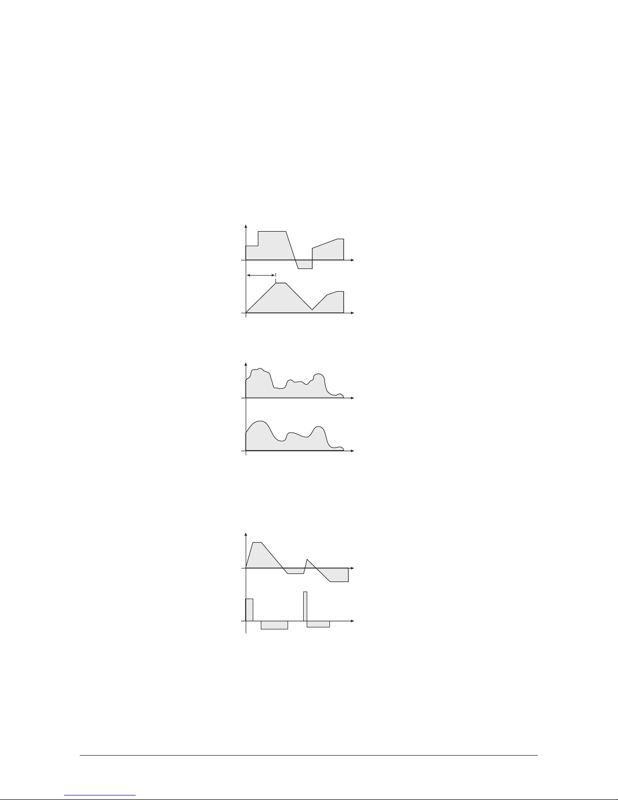
abs value
Returns the value of Source #1 without its sign. Negative values are
converted to their corresponding positive amounts. Parameter has no
function here. This function can be used e.g. for converting a bipolar
modulation source to a unipolar one, like opening the filter via Pitchbend
independent of the bending direction.
min value
Returns the minimum value of either Source #1 or Parameter.
max value
Returns the maximum value of either Source #1 or Parameter.
lag proc.
The lag processor creates a linear ramp from its current value, which is
initially minimum, to the value of Source #1. Then the ramp is stopped
until Source #1 changes again. The ramp time is specified by Parameter.
This function is useful when you want to apply a definable modulation over
a specified time, e.g. Modwheel controlled ramp for oszillator sweeps.
filter
Performs a low pass filter function on Source #1. The filter frequency is
determined by Parameter’s value. Use this function to smooth a signal.
diff.
Performs a differential function on Source #1. The result of this function
represents the speed of value change in the selected source. Parameter has
no function here. This function is useful to detect if a source signal has
changed, e.g. the Modwheel was turned.
Parameter
0…127
Defines a value for modifier functions that require a constant parameter. See the Type
parameter described above for further details.
Source #1
Differential function
Time
Level
Source #1
Filter function
Time
Level
Source #1
Lag processor function
Parameter
Time
Level
84
User’s Manual MicroWave II • MicroWave XT • XTk
Page 85
Modulation Matrix
A modulation can be described as influencing a sound parameter by a signal generating
unit. The terms used in this context are "source" and "destination". The MicroWave II/XT/XTk
offers 16 independent modulation units each with individual settings of source, destination
and amount.
Mod 1…16
Source
see Table 3
Defines the modulation source. See Table 3 for the list of available sources.
Amount
-64…+63
Determines the amount of modulation applied to the destination. Since the modulation is
in fact a multiplication of the source signal and this parameter, the resulting amplitude
depends on the type of modulation source you select:
• For the so-called unipolar modulation sources, the resulting amplitude lies within
the range of
0…+1
, if Amount is positive or
0…-1
, if Amount is negative. These
sources are: Filter Envelope, Amplifier Envelope, Wave Envelope, all MIDI
controllers including Modwheel, Foot control etc., Velocity, Release Velocity,
Aftertouch, Polyphonic Pressure and MIDI clock.
• For the so-called bipolar modulation sources, the resulting amplitude lies within
the range of
-1…0…+1
. These sources are: Free Envelope, both LFOs, Keytrack,
Keyfollow and Pitchbend.
For the modulation sources Keytrack and Keyfollow, a value of
+56
represents 100% of the
scale.
Source | Amount | Destination [5]
Modwheel | +047 | Wave1 Pos
User’s Manual MicroWave II • MicroWave XT • XTk
85
Page 86

Destination
see Table 5
Defines the modulation destination. The table below shows all possible settings for this
parameter:
Table 5: Modulation destinations
Program Name
This page is designed to name the Sound program. You can use up to 16 characters for this
purpose.
Name
First select the character to be modified via the first value dial. Then change its setting via
the second value dial.
Position | Character
01 | U Saw Repeat WMF
Setting Description
Pitch
Global pitch off all oscillators
Osc1 Pit.
Oscillator 1 pitch
FM Amount
Amount of frequency modulation
Osc2 Pit.
Oscillator 2 pitch
Wave1 Pos
Wave 1 startposition
Wave2 Pos
Wave 2 startposition
Wave1 Mix
Mixer input level Wave 1
Wave2 Mix
Mixer input level Wave 2
Ringmod
Mixer ringmodulation level
Noise Mix
Mixer noise level
Cutoff
Filter 1 cutoff frequency
Resonance
Filter 1 resonance
Filter 2
Filter 2 cutoff frequency
Volume
Amplifier master volume
Panning
Amplifier pan position
FE Attack
Filter Envelope attack
FE Decay
Filter Envelope decay
FE Sustain
Filter Envelope sustain
FE Release
Filter Envelope release
AE Attack
Amplifier Envelope attack
AE Decay
Amplifier Envelope decay
AE Sustain
Amplifier Envelope sustain
AE Release
Amplifier Envelope release
WE Times
All Wave Envelope times
WE Levels
All Wave Envelope levels
Free Env T
All Free Envelope times
Free Env L
All Free Envelope levels
LFO1 Rate
LFO 1 rate
LFO1 Level
LFO 1 level
LFO2 Rate
LFO 2 rate
LFO2 Level
LFO 2 level
M1 Amount
Amount of modulation assignment 1
M2 Amount
Amount of modulation assignment 2
M3 Amount
Amount of modulation assignment 3
M4 Amount
Amount of modulation assignment 4
86
User’s Manual MicroWave II • MicroWave XT • XTk
Page 87
Multi Mode
Multi parameters
The Multi parameters consist of settings which are common to all instruments in a multi
program.
Volume
Tempo
Controls
Keyboard Control
Name
Multi Volume
0…127
Determines the master volume for the multi program.
Arpeggiator Tempo
extern / 50…300
This setting allows one to define a master tempo for all instruments in the multi program. If
extern
is selected, the tempo is determined by MIDI clock.
Control W…Control Z
0…120 / global
These parameters are used to define modulation sources that are freely definable MIDI
controllers. Each value represents a MIDI controller number that is used when you assign
its parameter as modulation source in the Modifiers or the Modulation Matrix. If
global
is
selected, the corresponding settings made in the global parameter section are used.
MIDI Send
global / specific
This setting determines the MIDI channel used for sending notes generated by the XTk’s
keyboard. If
global
is selected, notes are sent on the basic channel selected in the global
parameters section. If
specific
is selected, notes are sent according to the settings of the
specific instruments.
Name
Use this page to set the multi program’s name. First select the character to be modified via
the first value dial. Then change its setting via the second value dial.
Position | Character
01 | M Hit Me Bigga WMF
MIDI Send
global
Control W|Control X|Control Y|Control Z
004 | 008 | 011 | 012
Multi Arpeggiator Tempo
130
Multi Volume
127
User’s Manual MicroWave II • MicroWave XT • XTk
87
Page 88
Instrument parameters
The Instrument parameters consist of individual settings for each Instrument in a multi
program.
Selecting an instrument for editing
Before you apply any edits to an Instrument’s parameter, you have to select the Instrument
to which the edits belong. Use the rightmost value dial 햾 to switch between the
Instruments.
Instrument Select (e.g. 1)
The instrument no. is always displayed when a parameter page with Instrument relating
settings is selected. This is also valid when editing a sound program in Multi Mode because
the sound program belongs to an Instrument. The no. is not displayed while editing Multi or
Global parameters.
When editing an Instrument’s Sound program, you can also switch among the Instruments
by turning the rightmost value dial 햾 when the Shift key 햽 is hold.
Sound
Sound 1
Sound 2
Sound 3
Bank
A / B
Selects the bank from which the sound program is taken.
Sound
001…128
Selects the instrument’s sound program.
Channel
global / omni / 1…16
Determines the MIDI receive channel for the instrument.
• If
omni
is selected, the Instrument receives on all channels.
• If
global
is selected, the MIDI channel defined in the global parameters is used.
Volume
0…127
Determines the master volume for the instrument.
Panning | PanMod | Output
center | normal | Main Out Inst. #1
Channel | Volume | Status
05 | 090 | on Inst. #1
Bank | Sound Saw Repeat WMF
A | A001 Inst. #1
Bank | Sound Saw Repeat WMF
A | A001 Inst. #1
88
User’s Manual MicroWave II • MicroWave XT • XTk
Page 89
Status
off / on
Status
off / Keys/MIDI / Keys / MIDI
Determines whether the instrument is disabled or enabled. On the XTk, you can determine
whether the selected instrument is played from the internal keyboard, incoming MIDI notes
or both.
Panning
left 64…center…right 63
Determines the position of the instrument within the stereo panorama. The value range
extends from
left 64
, which means far left, over the
center
position to
right 63
, which
means far right.
PanMod
off / normal / inverse
This setting decides whether panning modulation is applied or not.
• When set to
off
, no panning modulation is done at all.
• When set to
normal
, panning modulation is applied as defined in the single
program that is used for the instrument.
• When set to
inverse
, panning modulation is done as before, but the modulation
signal is negated and, as a result, the stereo sides are exchanged.
Output
Main Out / Sub Out
Selects the audio output on which the instrument’s signal will appear.
Main
routes the
instrument to the main outputs Main Out Left/Stereo 쐇 and Main Out Right Mono 쐋,
Sub
routes it to the sub outputs Sub Out Left/Stereo 쐏 and Sub Out Right Mono 쐄.
Tune
Tune
Transpose
-48…+48
Allows one to transpose the instrument in steps of a semitone.
Detune
-64…+63
Fine-tunes the instrument in increments of 64ths of a semitone.
MIDI Send
off / on
This XTk parameter is accessible only if the Multi parameter MIDI Send is set to
specific
. If
set to
on
, this instrument will send notes on the instrument’s selected MIDI channel.
Range
Range 1
Range 2
Lowest | Highest Key
000 | 127 Inst. #1
Lowest | Highest Velocity
001 | 063 Inst. #1
Transpose| Detune
+12 | +00 Inst. #1
User’s Manual MicroWave II • MicroWave XT • XTk
89
Page 90
Lowest Velocity
1…127
This parameter allows you to limit the velocity range in which the instrument is played.
Only notes with a velocity higher or equal to the selected value are passed through. Set this
parameter to
1
, if you want to turn velocity switching off.
Highest Velocity
1…127
Counterpart to the Lowest Velocity parameter. Only notes with a velocity lower or equal
to the selected value are passed through. Set this parameter to
127
, if you want to turn
velocity switching off.
Lowest Key
0…127
Equivalent to the velocity switching parameters, you can restrict the key range used for the
instrument’s tone generation. Only notes with a key number higher or equal to the selected
value are passed through. Set this parameter to
0
if you want to use the full keyboard range.
Highest Key
0…127
Counterpart to the Lowest Key parameter. Only notes with a key number lower or equal
to the selected value are passed through. Set this parameter to
127
if you want to use the
full keyboard range.
Arpeggiator
Every Instrument in a Multi mode program is capable of using its own arpeggiator. The
settings made in this section override the settings defined in the Instrument’s Sound
program. All Instruments will use the tempo setting defined in the Multi Arpeggiator
Tempo parameter, because it makes no sense to use different settings for each Instrument.
Alternatively, you can use the original settings of the Sound program by using the
corresponding option in the Active parameter.
Arpeggiator 1
Arpeggiator 2
Arpeggiator 3
Active
off / on / hold / Sound Arp
Enables or disables the arpeggiator or activates the
hold
mode. When
hold
is activated,
incoming MIDI chords generate continuous arpeggios even when the chord is released. If
Sound Arp
is selected, the arpeggiator uses the settings defined in the Sound program that
builds the instrument.
Clock
1/1…1/32
Determines the note value for whole notes to thirty-second notes. The basis is a 4/4 beat.
Triplets (e.g.
1/8T
) and dotted notes (e.g.
1/16.
) are available for every value.
Velocity | Reset on Pattern Start
root note| off Inst. #1
Pattern |Direction|Note Order
off | up | by note Inst. #1
Active | Clock | Range
Sound Arp| 1/2 | 02 Inst. #1
90
User’s Manual MicroWave II • MicroWave XT • XTk
Page 91

Range
1…10
Determines the range of the single notes in octaves.
Pattern
off / user / 1…15
Determines whether an rhythm pattern is played and which one.
• If
off
is selected, the arpeggiator playes its notes in regular steps, specified by the
Clock parameter.
• If
user
is selected, the arpeggiator uses the free programmable pattern defined in
the
Arpeggiator User Pattern
page of the sound program. The instrument itself does
not provide a user pattern.
• Additionally, the arpeggiator features 15 preset rhythm patterns. These are
numbered from
1
through 15.
See diagram 4 in chapter "Sound Parameters" to get detailed information about patterns.
Direction
up / down / alternate / random
Determines the sequence of generated notes according to pitch.
• If
up
is selected, the arpeggio starts at the lowest note and sweeps up through the
notes until it reaches the highest note. It then starts at the bottom again.
• If
down
is selected, the arpeggio starts at the highest note and sweeps down
through the notes until it reaches the lowest note. It then starts at the top again.
• If
alternate
is selected, the arpeggio starts at the lowest note and sweeps up through
the notes until it reaches the highest note. It then starts to sweep back down.
• If
random
is selected, the arpeggio plays any of the notes in a random order.
NoteOrder
by note / note rev. / as played / reversed
Determines the sequence of generated notes according to note order.
• If
by note
is selected, the arpeggio sequence is sorted by the MIDI note number.
This is the standard mode, used by most arpeggiators.
• If
note rev.
is selected, the arpeggio sequence is sorted in the exactly reversed
order to the
by mode
setting.
• If
as played
is selected, the arpeggio is generated in the order of the incoming
notes. In combination with the user programmable pattern this feature offers a
small but effective step sequencer.
• If
reversed
is selected, the arpeggio is generated in the reverse order of the
incoming notes.
To understand the difference of the individual settings, it is nessessary to "step-input" the
notes of the chord as described in the chapter "Arpeggiator" of the sound parameters.
Velocity
root note / last note
Determines how the velocity values of the generated notes are calculated.
• If
root note
is selected, every generated note inherits its velocity from its base note.
E.g. if the base chord for the arpeggio contains an E with a certain velocity, all
generated E notes also have this velocity value, independent of their octave setting.
• If
last note
is selected, every generated note has the same velocity as the last
incoming note.
User’s Manual MicroWave II • MicroWave XT • XTk
91
Page 92

Reset on Pattern Start
off / on
Selects if the arpeggiator is reset each time the rhythm pattern starts again. If the setting is
disabled, the arpeggiator plays all chord notes from the first to the last and over again,
regarding the sequence determined by Direction and Note Order. If the setting is enabled,
the arpeggiator only plays the number of chord notes that correspond to the pattern length.
Then it starts with the first chord note at its basic octave again. The result is similar to
pressing the chord again each time the pattern restarts.
92
User’s Manual MicroWave II • MicroWave XT • XTk
Page 93
Global Parameters
Global parameters are settings that influence the MicroWave II/XT/XTk’s general response.
These are determined separately from the programs and stored in a special memory
location. Global parameters are stored automatically when switching off the device.
MIDI 1
MIDI 2
MIDI 3
Controls
Keyboard
Sustain Pedal
Volume
Volume
Tune
System
Channel
omni / 1…16
Sets the basic send and receive channel for the MicroWave II/XT/XTk. This setting is valid
for all Sound programs and for Instruments of a Multi program whose Channel parameter
is set to
global
. If
omni
is selected, the MicroWave II/XT/XTk sends on channel 1 and
receives on all channels.
Display timeout | Contrast
064 | 100
Master Tuning | Transpose
440 Hz | +00
Main Volume |Input Gain
100 | 2
Main Volume
100
Pedal Type
closing
KB Send |Vel.Curve|R-Vel. C.|Prs.Curve
8 | lin | off | log2
Control W|Control X|Control Y|Control Z
004 | 008 | 011 | 012
MIDI Clock | Send |
| off |
Parameter Control | Send | Receive
|Ctl+SysEx| on
Channel |PrgChange|BendRange|Device ID
12 | multi | 012 | 000
User’s Manual MicroWave II • MicroWave XT • XTk
93
Page 94

PrgChange
sound / multi / combined
Determines the way MIDI Program Change messages are processed.
• If
sound
is selected, program changes are used to select Sound programs for the
Instrument that receives on the corresponding MIDI channel.
• If
multi
is selected, the whole Multi program is switched by program changes, that
are received on the basic channel set above.
• If
combined
is selected, Instrument programs can be changed by using the
Instrument’s channel, the Multi can be changed by using the basic channel.
BendRange
0…120 / harmonic
Determines the intensity of the pitchbend via MIDI Pitchbend messages in semitones. If
harmonic
is selected, the pitchbend is performed in steps of the harmonic and subharmonic
scale. Please refer to the chapter "Oscillator" to get further information about the harmonic
scale. This setting is valid for all programs whose oscillator Pitchbend Range parameter is
set to
global
.
Device ID
0…126
Defines the device identification number for system exclusive data transmission.
Transmission will only be executed successfully if the sender and receiver setting coincide.
Device ID
127
is a so-called broadcast ID that addresses all connected MicroWave
II/XT/XTks. The MicroWave II/XT/XTk can receive this from other devices, but cannot send it
itself. This function is limited to special computer software.
Par. Control Send
off / Ctl only / SysEx / Ctl+SysEx
Determines which type of data is sent from the MicroWave II/XT/XTk via MIDI.
• If
off
is selected, no data is sent.
• If
Ctl only
is selected, only controller messages are sent. Parameters without
dedicated controller assignment are not sent at all.
• If
SysEx
is selected, only system exclusive data is sent. This has the advantage that
the parameter change is not channel based but instrument based, which can avoid
unwanted parameter changes of layered sounds. The disadvantage is a larger
amount of data that is transferred.
• If
Ctl+SysEx
is selected, both controller messages and system exclusive data is sent.
Par. Control Receive
off / on
Enables or disables the receiving of parameter control messages via MIDI. These messages
include controller and system exclusive data.
MIDI Clock Send
off / on
Enables or disables the sending of MIDI clock. This setting should be enabled in those
cases, where you want to use the MicroWave II/XT/XTk’s arpeggiator as master for
controlling the tempo.
When MIDI Clock Send is enabled while the MicroWave II/XT/XTk’s MIDI In and Out
are connected to your sequencer, you will probably get a MIDI loop. A total hangup
of your system may result. Ensure to disable the MicroWave II/XT/XTk’s MIDI clock
sending feature in such a case.
94
User’s Manual MicroWave II • MicroWave XT • XTk
Page 95
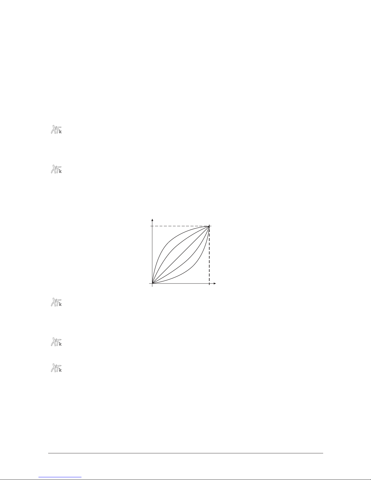
Control W…Control Z
0…120
These parameters are used to define modulation sources that are freely definable MIDI
controllers. Each value represents a MIDI controller number that is used when you assign
its parameter as modulation source in the Modifiers or the Modulation Matrix. The settings
made here are only valid for Sound programs because each Multi program has its own set
of Control W…Control Z parameters.
☞ Example: You want to control the LFO1 speed via MIDI controller #49. To do so, set
Control W to
49
first. Then, setup an entry in the Modulation Matrix of your sound
program with
Control W
as source and
LFO1 Rate
as destination and apply an
suitable amount. In the same way you can use Control X…Control Z for further
assignments.
KB Send
off / 1…16
Sets the MIDI send channel for the XTk keyboard. If the XTk is in Multi mode, the Multi
parameter MIDI Send determines whether the
global
channel set by this parameter is used
or the
specific
channel of the currently selected instrument.
Vel.Curve
exp2 / exp1 / lin / log1 / log2 / fix32…fix127
Determines the dynamic response curve of the XTk’s keyboard velocity. By selecting one of
the
fix
values, the dynamic velocity will be disabled and all notes are sent with the same
velocity. E.g. if you select
fix100
, each note played on the keyboard will have a velocity of
100
.
R-Vel. C.
off / exp2 / exp1 / lin / log1 / log2 / fix32…fix127
Same as Vel.Curve but determines the response of the keyboards release velocity. If
off
is
selected, the release velocity feature is disabled and a '90' message is sent for 'Note off'
instead of the '80' message that is sent if release velocity is enabled.
Prs. Curve
exp2 / exp1 / lin / log1 / log2
Determines the dynamic response of the XTk’s keyboard aftertouch.
Pedal Type
closing / opening
Sets the polarity of the sustain pedal connected to the Pedal / CV In 1 쐅 jack. If you are
not sure what type of pedal you have, try to use the
closing
option first. If the sustain
feature works in the opposite direction, i.e. notes are sustained without pressing the pedal,
try to use the
opening
setting.
Main Volume
0…127
Adjusts the master volume of all MicroWave II/XT/XTk’s programs on both outputs. This
setting is also accessible from the Play page.
Key Velocity
MIDI
Note
Velocity
lin
log1log2
exp1 exp2
127
0
min max
User’s Manual MicroWave II • MicroWave XT • XTk
95
Page 96

Input Gain
1…4
Sensitivity of the external audio input Analog In 쐎.
Master Tuning
430…450 Hz
Determines the MicroWave II/XT/XTk’s overall pitch. The value specified here is the
reference pitch for MIDI note A3. The default setting is 440Hz, which is commonly used by
most instruments.
You should only change this setting if you really know what you’re doing. You will
have to adjust all your other instruments, too. Don’t forget to set it back again!
Transpose
-12…+12
Allows one to set a global pitch transpose for all programs of the MicroWave II/XT/XTk.
Display timeout
0…127
Determines how long the page names are displayed in the upper right corner when calling
a parameter page via the page dial 햴. You may want to decrease the value or set it to
0
after you have got some experience with the MicroWave II/XT/XTk.
Contrast
0…127
Sets the display contrast.
96
User’s Manual MicroWave II • MicroWave XT • XTk
Page 97

MIDI Control
This chapter describes the MIDI control options of the MicroWave II/XT/XTk.
Selecting Programs
Calling Programs via Program Change
All of the MicroWave II/XT/XTk’s Sound and Multi programs can be called via MIDI
Program Change messages and MIDI Bank Select messages. As the device contains 128
programs in each bank, it recognizes program number
0…127
. To select the bank, you
have to use a Bank Select message:
• Bank 0 contains Sound Programs
A001…A128
• Bank 1 contains Sound Programs
B001…B128
When the MicroWave II/XT/XTk is in Multi mode, you have three options, how Program
Change and Bank Select messages work. By means of the Global parameter PrgChange
you can determine if a Sound program inside the current Multi Program is changed, the
whole Multi program is changed, or if both methods are used in combination.
Influencing Sounds via MIDI Messages
Controllers as Modulation Sources
The controllers Modwheel and Breath Control are always used as modulation sources. The
freely-definable Control X…Z can also be used as a modulation source. X…Z stands for
definable controller numbers
1…120
. Use these controllers in the Modifiers and the
Modulation Matrix.
Changing Sound Parameters via Controllers
Every important parameter is assigned a controller number through which the parameter
can be changed. If a parameter is changed at the device, then this change is sent along
with the appropriate controller number via MIDI. This is especially helpful when you want
to record changes you made at the MicroWave II/XT/XTk to a sequencer.
All controller messages are sent and received via the channel defined in the global
parameters or, if in Multi mode, selected for the corresponding Instrument. The appendix of
this manual contains a table listing the controller numbers and the sound parameters they
are assigned to.
Pitchbending
The Pitchbend Range parameter of the oscillators lets you define to what extent a
pitchbend message influences the pitch of the MicroWave II/XT/XTk. Pitchbend is also
available as a modulation source.
Aftertouch and Poly Pressure
Aftertouch and Poly Pressure are available as modulation sources in the MicroWave
II/XT/XTk. They can be used for any application where control change messages are
accepted.
System Exclusive Data
All parameters of the MicroWave II/XT/XTk can be controlled by system exclusive data. You
can find a detailed description of the commands and data formats in the appendix.
User’s Manual MicroWave II • MicroWave XT • XTk
97
Page 98
System Exclusive Data Transmission
System exclusive data transmission lets you send and receive the contents of the
MicroWave II/XT/XTk’s memory via MIDI (dump).
Sending System Exclusive Data
When you activate the send functions, the MicroWave II/XT/XTk sends the contents of its
memory to the MIDI Out jack . Using a sequencer, you can record and archive this data.
☞ This is how you activate the dump function:
1. Press and hold the Shift key 햽.
2. Briefly press the Utility key 햷.
3. Release the Shift key 햽.
4. The display shows a page where you can select the dump type:
Dump
5. Use the page dial 햴 to select the desired dump function:
• If
Sound
is selected, the current Sound program will be sent. When used in
Multi mode, the Sound program of the currently selected instrument will be
sent.
• If
Multi
is selected, the current Multi program will be sent. The Sound
programs that made up the Multi are not sent. This function is only available
in Multi mode.
• If
Arrangement
is selected, the current Multi program with all its used Sound
programs is sent. Use this function to dump all settings of a Multi. This
function is only available in Multi mode.
• If
All Sounds
is selected, all Sound programs of the MicroWave II/XT/XTk are
sent.
• If
All Multis
is selected, all Multi programs of the MicroWave II/XT/XTk are
sent.
• If
All Wavetables & Waves
is selected, all Wavetables & Waves are dumped.
• If
Global Parameters
is selected, all Global parameters are dumped.
• If
Everything
is selected, all previous mentioned dumps are sent sequentially.
• If
Sound Controller Data
is selected, the parameters of the currently selected
Sound that have an associated MIDI controller are all sent via MIDI out. This
is useful when working with some editing software.
• If
System
is selected, the Operating System is sent via MIDI out. Use this
function to update another MicroWave II/XT/XTk. You can also update an
XT/XTk using a MWII or any other combination because the operating
system is the same for all devices. Furthermore, you can record the data
using a sequencer.
• If
Reorganize Memory
is selected, the file system is reorganized. Use this
function before sending numerous dump messages to the MicroWave.
Dump Sound A001 Saw Repeat WMF ?
[confirm with <Shift-Utility>]
98
User’s Manual MicroWave II • MicroWave XT • XTk
Page 99

6. Briefly press the Utility key 햷 while holding the Shift key 햽 again.
See appendix for detailed information on system exclusive specifications.
Depending on the selected type, the dump may take some time. The MicroWave
II/XT/XTk cannot be played during this time.
Receiving System Exclusive Data
You are not required to activate a special receive mode at the MicroWave in order to
receive system exclusive data via MIDI. The transmission is activated via a Dump Request
command originating at the device that is sending the messages. However there are a few
things you should check prior to the transmission:
• Check out the parameter Device ID. Data transmission will only be executed
successfully if the sender and receiver setting coincide.
• Make sure none of the MicroWave II/XT/XTk’s programs are in Edit mode. All edit
buffers are cleared via data transmission and therefore all edits that were not stored
prior to the dump will be irretrievably lost!
After activating the dump command at the sender device, the MicroWave II/XT/XTk will
receive data and store these in its memory.
When the MicroWave II/XT/XTk receives a Sysex dump with the device ID
127
, it
will always accept the dump, regardless of the setting of its Device ID parameter.
Device ID
127
is a so-called "Broadcast ID" that addresses all connected MicroWave
II/XT/XTks. The MicroWave II/XT/XTk can receive this from other devices, but it
cannot send a Broadcast ID to other devices. This function is limited to special
computer software.
Also a checksum of
127
is always accepted as valid.
User’s Manual MicroWave II • MicroWave XT • XTk
99
Page 100
Other Functions
Updating the System Software
The MicroWave II/XT/XTk has an service-friendly feature that makes it possible to update
the system software without changing any parts.
All software updates come in the form of a standard MIDI file that can be read by every
sequencer. The fastest way to get this file is by downloading it from our web site at
http://www.waldorf-gmbh.de/mw2/system.html.
If you don’t have Internet access, please ask your local dealer for a disk copy.
Software version 2.1.8 or later is required for the XTk model. Do not under any
circumstances try to dump an earlier version into the XTk. A total loss of data may
occur and there is no way to make the XTk work again!
☞ This is how you update the MicroWave II/XT/XTk’s system software:
1. Load the standard MIDI file with the system software into your sequencer. Follow
the instructions from your sequencer’s manual.
2. The MIDI file consists of one single track with several sysex messages within. Make
sure that this track is assigned to the MicroWave II/XT/XTk so that it can receive the
data.
3. Start the sequencer to play the file and send the track data to the MicroWave
II/XT/XTk.
4. The MicroWave II/XT/XTk will display a message that informs that update is in
progress:
5. Wait until the operation is completed. If updating was successful, the MicroWave
II/XT/XTk will show the following message:
Do not under any circumstances turn off the MicroWave II/XT/XTk when this step is
in progress. A total loss of data may occur and there is no way to make it work
again!
6. After a few seconds the message disappears. The MicroWave II/XT/XTk is now
ready to work again.
If something goes wrong with updating, the MicroWave II/XT/XTk displays an error
message. If such a thing happens, try updating again. In some cases it can be
necessary to adjust the sequencer tempo before playing the file so that the data
events are sent more slowly. You should also deactivate the transmission of MIDI
Timecode and MIDI Clock.
Updating System...
Receiving System Update...
100
User’s Manual MicroWave II • MicroWave XT • XTk
 Loading...