

Waldorf RN8200E, RN8400E, RN8600E, RNL8200E, RNL8400E Installation And Operation Manual
...
1
Installation and Operation Manual
Electric Cooktop
Series
RN8200E
RN8400E
RN8600E
Date Purchased
Serial Number
Dealer
Service Provider
230558-7
For use in GB & IE
RNL8200E
RNL8400E
RNL8600E

The reproduction or copying of any part of this manual by any means whatsoever is strictly forbidden unless authorized previously in
writing by the manufacturer.
In line with policy to continually develop and improve its products, Moffat Ltd. reserves the right to change the specifications and
design without prior notice.
© Copyright Moffat Ltd. July 2009.
MANUFACTURED BY
Moffat Limited
PO Box 10001
Christchurch
New Zealand
Ph: (03) 389 1007
Fax: (03) 389 1276
WORLD-WIDE BRANCHES
UNITED KINGDOM
Blue Seal
67 Gravelly Business Park
Gravelly Park
Birmingham
West Midlands
B24 8TQ
Ph: (121) 327 5575
Fax: (121) 327 9711
UNITED STATES
Moffat Inc
3765 Champion Blvd
Winston-Salem
North Carolina 27115
Ph: (336) 661 0257
Fax: (336) 661 9546
CANADA
Serve Canada
22 Ashwarren Road
Downview
Ontario M3J1Z5
Toll Free:800 263 1455
Ph: (416) 631 0601
Fax: (416) 631 0315
info@servecanada.com
www.servecanada.com
www.moffat.com
NEW ZEALAND
Christchurch
Auckland
Moffat Limited Moffat Limited
PO Box 10-001 4 Waipuna Road
16 Osborne Street Mt Wellington
Christchurch Auckland
Ph: (03) 389 1007 Ph: (09) 574 3150
Fax: (03) 389 1276 Fax: (09) 574 3159
AUSTRALIA
Victoria
New South Wales
Moffat Pty Limited Moffat Pty Limited
740 Springvale Road 3/142 James Ruse Drive, Rose Hill
Mulgrave, Melbourne PO Box 913, Smithfield
Victoria 3171 Sydney, N.S.W. 2142
Ph: (03) 9518 3888 Ph: (02) 8833 4111
Fax: (03) 9518 3838 Fax: (02) 8833 4133
Western Australia
Queensland
Moffat Pty Limited Moffat Pty Limited
67 Howe Street 30 Prosperity Place
Osbourne Park Geebung, Brisbane
WA 6017 Queensland 4034
Ph: (08) 9202 6820 Ph: (07) 3630 8600
Fax: (08) 9202 6836 Fax (07) 3630 8623

1
Waldorf Electric Cooktops
RN(L)8200E Electric Cooktop - 300 mm.
RN(L)8400E Electric Cooktop - 600 mm.
RN(L)8600E Electric Cooktop - 900 mm.
Introduction .............................................................................................. 2
Specification .............................................................................................. 3
Model Numbers Covered in this Specification
General
Electrical Supply Requirements
Electrical Connection
Dimensions ................................................................................................ 5
Installation ..............................................................................................10
Installation Requirements
Unpacking
Location
Clearances
Assembly
Fitting Adjustable Feet / Rear Rollers to Leg Stand Units
Fitting Adjustable Feet / Rear Rollers to Cabinet and Refrigeration Bases
Electrical Connection
Commissioning
Operation.................................................................................................14
Operation Guide
Radiant Hotplates
Griddle Plates
Cleaning and Maintenance ......................................................................16
General
After Each Use
Daily Cleaning
Weekly Cleaning
Periodic Maintenance
Fault Finding............................................................................................ 19
Circuit Schematics ...................................................................................20
Replacement Parts List............................................................................24
Contents
2
We are confident that you will be delighted with your WALDORF ELECTRIC COOKTOP, and it will become a
most valued appliance in your commercial kitchen.
To ensure you receive the utmost benefit from your new WALDORF Appliance, there are two
important things you can do.
Firstly:
Please read the instruction book carefully and follow the directions given. The time taken will be well
spent.
Secondly:
If you are unsure of any aspect of the installation, instructions or performance of your appliance,
contact your WALDORF dealer promptly. In many cases a phone call could answer your question.
CE Only:
These instructions are only valid if the country code appears on the appliance. If the code does not
appear on the appliance, refer to the supplier of this appliance to obtain the technical instructions for
adapting the appliance to the conditions for use in that country.
WARNING:
I
MPROPER INSTALLATION, ADJUSTMENT, ALTERATION, SERVICE OR MAINTENANCE CAN CAUSE PROPERTY
DAMAGE, INJURY OR DEATH. READ THE INSTALLATION, OPERATING AND MAINTENANCE INSTRUCTIONS
THOROUGHLY BEFORE INSTALLING OR SERVICING THIS APPLIANCE.
WARNING:
G
REAT CARE MUST BE TAKEN BY THE OPERATOR TO USE THE EQUIPMENT SAFELY TO GUARD IT AGAINST RISK
OF FIRE.
• T
HE APPLIANCE MUST NOT BE LEFT ON UNATTENDED.
• I
T IS RECOMMENDED THAT A REGULAR INSPECTION IS MADE BY A COMPETENT SERVICEMAN TO ENSURE
CORRECT AND SAFE OPERATION OF YOUR APPLIANCE IS MAINTAINED.
• DO NOT
STORE OR USE GASOLINE OR OTHER FLAMMABLE VAPOURS OR LIQUIDS IN THE VICINITY OF
THIS OR ANY OTHER APPLIANCE.
•
DO NOT SPRAY AEROSOLS IN THE VICINITY OF THIS APPLIANCE WHILE IT IS IN OPERATION.
C
AUTION
:
This appliance is;
•
For professional use and is only to be used by suitably qualified / trained
persons.
•
Only qualified service persons are to carry out installation, servicing and
gas conversion operations.
•
Components having adjustments protected (e.g. paint sealed) by the
manufacturer should not be adjusted by the user / operator.
•
DO NOT operate the appliance without the legs supplied fitted.
Introduction

3
Specifications
Model Numbers Covered in this Specification
RN[1]8200E-[2] 2 Open Radiant Elements.
RN[1]8203E-[2] 300 mm Griddle.
RN[1]8400E-[2] 4 Open Radiant Elements.
RN[1]8403E-[2] 2 Open Radiant Elements / 300 mm Griddle.
RN[1]8406E-[2] 600 mm Griddle.
RN[1]8600E-[2] 6 Open Radiant Elements.
RN[1]8603E-[2] 4 Open Radiant Elements / 300 mm Griddle.
RN[1]8606E-[2] 2 Open Radiant Elements / 600 mm Griddle.
RN[1]8609E-[2] 900 mm Griddle.
NOTE:
[1]: - Back Options;
- - Standard Models.
L - Low Back Models.
[2] - Base Stand Options;
B - Bench Mount.
CB - Cabinet Base (excluding RN8200G series).
LS - Leg Stand (excluding RN8200G series).
RB - Refrigerated Base (RN8600G and RN8800G series only).
General
A commercial heavy duty, high efficiency Cooktop for modular kitchens, constructed in easy clean
stainless steel external finish. Hinge-up elements and griddle sections and all services are accessed
from the front of the units. It has a high option hob/griddle arrangement with 300 mm, 600 mm or
900 mm griddle or open radiant element options.
It is available on industrial adjustable feet. With 4 models of base unit available from the RN8600 to
RN8900 models. (Model RN8400 is not available with Refrigeration Base option and Model RN8200
is only available in Bench Model).

4
Specifications
Electrical Supply Requirements
Electrical Connection
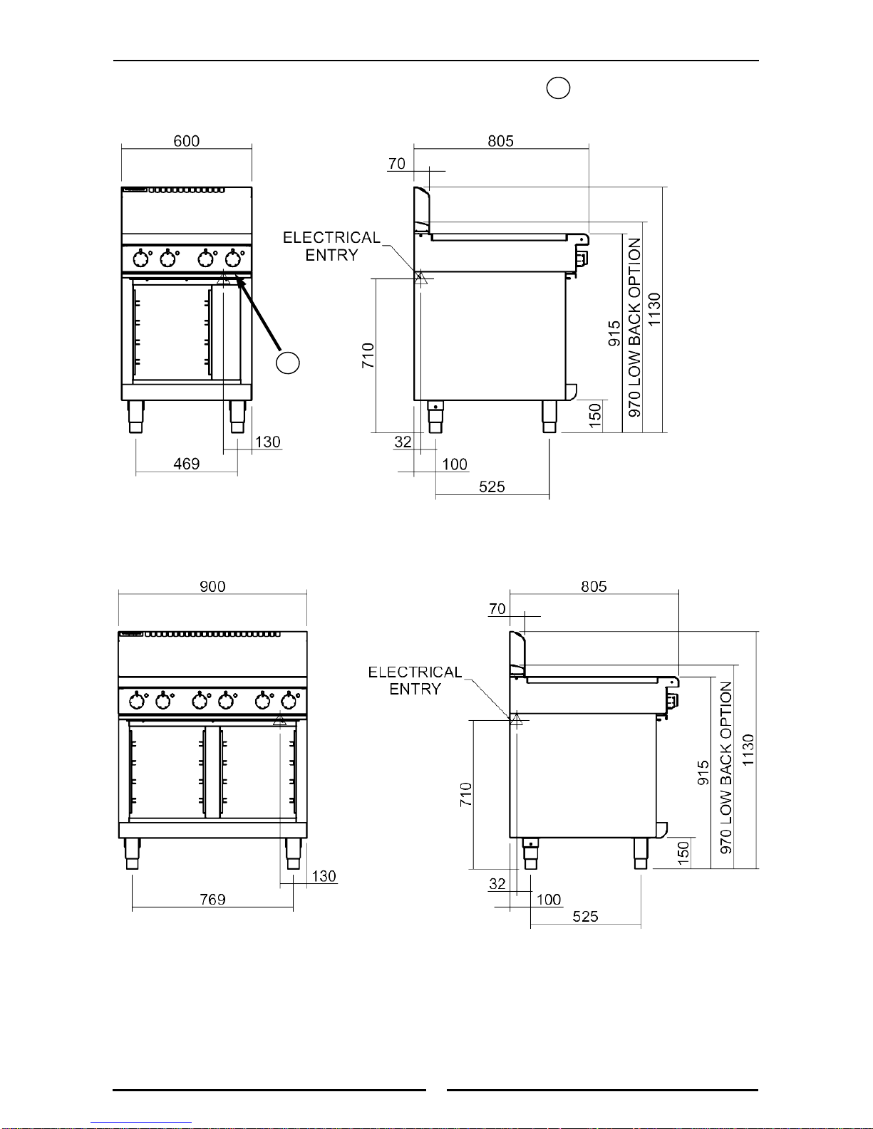
On Leg Stand, Cabinet Base and Refrigeration Base Models, the electrical supply connection
point is located at the rear of the appliance, approximately 130 mm from the right hand side and 32
mm from the rear of the appliance and 710 mm from the floor.
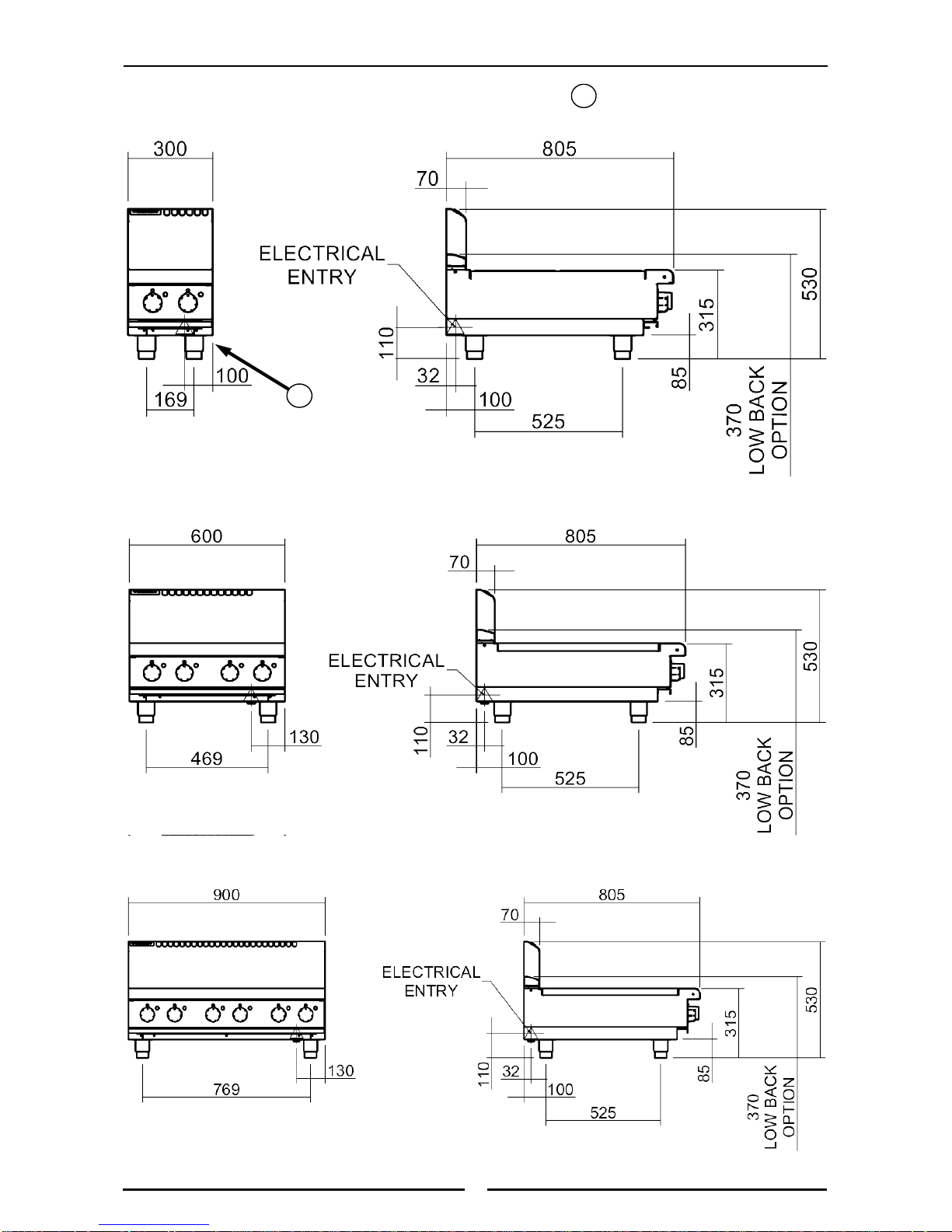
On RN8200E Bench Models the connection point is located approx 100 mm from the right hand
side, 110 mm from bench height and 32 mm from the rear.
On RN8400E and RN8600E Bench Models the connection point is located approx 130 mm from
the right hand side, 110 mm from bench height and 32 mm from the rear. (Refer to the
‘Dimensions’ section).
When connecting a this electric appliance to the mains supply, ensure that the following is carried
out:-
• An isolating switch is fitted within 2 m of the appliance, but not on the appliance and in
such a position that the user does not have to reach across the cooking surface.
• Supply cord shall be oil-resistant, sheathed flexible cable and not lighter than ordinary
polychloroprene or other equivalent synthetic elastomer sheathed cord (as per AS/NZS
3191 part 2.10.11. or IEC 60245-IEC-57) e.g. HO5 RN-F Type.
• The branch supply line shall be individually overload protected to the correct current rating
and the supply chord shall be protected against any mechanical or thermal damage.
• A grommet is fitted around the wiring entry hole into the appliance.
• All wiring connections must be tight.
Refer to the appropriate wiring standards for the size of cable that is to be supplied to an appliance
for the current drawn on that line.
WARNING:
T
HIS APPLIANCE MUST BE EARTHED. IF THE SUPPLY CORD IS DAMAGED, IT MUST BE REPLACED BY A SUITABLY
QUALIFIED PERSON IN ORDER TO AVOID A HAZARD.
For the Refrigeration Cabinet Specifications, refer to the Refrigeration Cabinet Installation and
Operation Manual supplied with the appliance.
Model
Power Supply
Total Power
Input
Amps
Voltage Type Frequency
L1 L2 L3
RN8200E
230-240 Vac 1 P+N+E 50 / 60 Hz 4.8 kW 20.0 --- ---
RN8203E
230-240 Vac 1 P+N+E 50 / 60 Hz 3.4 kW 14.2 --- ---
RN8400E
400-415 Vac 2 P+N+E 50 / 60 Hz 9.6 kW 20.0 20.0 ---
RN8403E
400-415 Vac 2 P+N+E 50 / 60 Hz 8.2 kW 14.2 20.0 ---
RN8406E
400-415 Vac 2 P+N+E 50 / 60 Hz 6.8 kW 14.2 14.2 ---
RN8600E
400-415 Vac 3 P+N+E 50 / 60 Hz 14.4 kW 20.0 20.0 20.0
RN8603E
400-415 Vac 3 P+N+E 50 / 60 Hz 13.2 kW 20.0 20.0 20.0
RN8606E
400-415 Vac 3 P+N+E 50 / 60 Hz 11.6 kW 14.2 14.2 20.0
RN8609E
400-415 Vac 3 P+N+E 50 / 60 Hz 10.2 kW 14.2 14.2 14.2
5
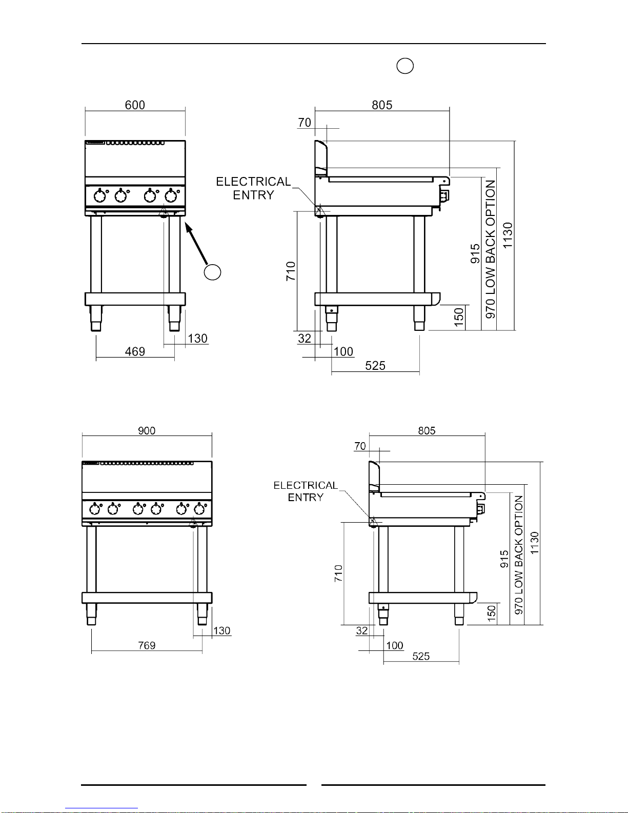
Dimensions
Dimensions for Bench Models
RN(L)8200E-B
RN(L)8600E-B
= Rating Plate Location for this
option.
R
RN(L)8400E-B
R
6
Dimensions
Dimensions for Cabinet Base Models
RN(L)8400E-CB
RN(L)8600E-CB
= Rating Plate Location for
this option.
R
R
7
Dimensions
Dimensions for Leg Stand Models
RN(L)8400E-LS
RN(L)8400E-LS
= Rating Plate Location for
this option.
R
R
 Loading...