

Page 1
GB Instructions for use Machine light ABLL 1
Safety instructions
! DANGER
Danger caused by wrong
mounting or handling!
Wrong mounting or handling of this
unit can result in serious injuries
or death.
¾ First read these ins -
tructions and, where
appropriate, any other
instructions and information
attached to the unit!
¾ Please observe the warnings
and notes included in the instructions and attached to the
unit!
! DANGER
This symbol identifies items that
may directly result in serious injuries or death in case of non-observance or wrong handling.
! WARNING
This symbol identifies items that
may result in serious injuries or
death in case of non-observance
or wrong handling.
! CAUTION
This symbol identifies items that
may result in injuries or material
damage in case of non-observance or wrong handling.
NOTICE
This symbol identifies items that
may result in material damage in
case of non-observance or wrong
handling.
19
Page 2
GB Instructions for use Machine light ABLL 1
Safety instructions
20
! DANGER
Explosion hazard!
Operating the light in rooms subject to explosion hazards can trigger an explosion.
¾ Operate in rooms not subject to
explosion hazards only!
! WARNING
Danger due to electrical shock
in case of contact!
Maintenance or repair work carried
out incorrectly may result in serious
injuries or death.
¾ Disconnect the light from the
mains before carrying out any
maintenance or repair work!
¾ Maintenance and repair work
must be carried out by a skilled
electrician only!
¾ Only parts released by the
manufacturer may be used as
spare parts!
NOTICE
Damage caused by wrong mains
voltage!
A wrong mains voltage can result in
damaging or destroying the lamp.
¾ Operate units of protec-
tion class III with safety
extra low voltage (SELV) only!
¾ Connection only by a skilled
electrician!
¾ Before putting the light into
operation, the user has to check
whether the mains voltage is
identical with the rated voltage
specified on the rating plate.
Page 3
GB Instructions for use Machine light ABLL 1
Safety instructions
! WARNING
Risk of blinding!
Looking directly into the light source may cause temporarily impaired
vision and afterimages. This may
result in irritations, inconveniences,
impairments or even accidents.
¾ Looking directly into the light
source must be avoided.
¾ Position light in such a way that
looking directly into the light
source is avoided.
NOTICE
Damage caused by the incident
laser beam!
Direct or indirect incidence of a
laser beam may result in the destruction of the LED.
¾ Use the light only outside the
range of action of high-performance lasers (e.g. cutting laser,
welding laser).
21
Page 4
GB Instructions for use Machine light ABLL 1
Description
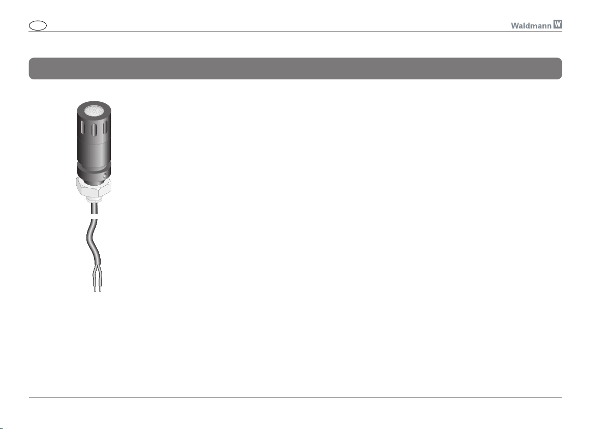
Fig. 11
According to standard DIN EN 1837, an illuminance of 500 lx is required in the work area of machines. This is
often impossible to achieve using a light that is not in the immediate proximity of the tool. However, only in rare
cases is it possible to attach a light directly to the tool slide, since the restricted room available in the interior of
the machine room does not allow this.
In the ideal case, a well illuminated machining area is can be achieved by combining 2 or more lights.
a) Light for basic illumination of the machining area (using, for example, a Waldmann protective-tube light).
b) Machine light attached directly to the tool slide (Waldmann machine light ABLL 1).
The machine light ABLL 1 meets the requirements of the standard, since its small dimensions allow it to be attached directly to the tool slide. Such an attachment, in addition to the basic illumination already in place, offers
a maximum degree of illumination comfort at the machine.
The use of light emitting diodes (LED) instead of halogen lights allows a significantly higher useful life to be
achieved. This results in fewer machine downtimes as a result of maintenance work.
A housing made of anodized aluminum and a protective borosilicate glass pane are resistant to hot and sharpedged chips. The housing is waterproof and, like the PUR cable, resistant to coolants and lubricants.
The selection between 2 variants of different radiation characteristics (Spot = 6°, Flood = 25°) makes for universal use.
22
Page 5
GB Instructions for use Machine light ABLL 1
Designated use Abbreviations and symbols
Intended purpose:
Machine light - light for illuminating
the work area on machines.
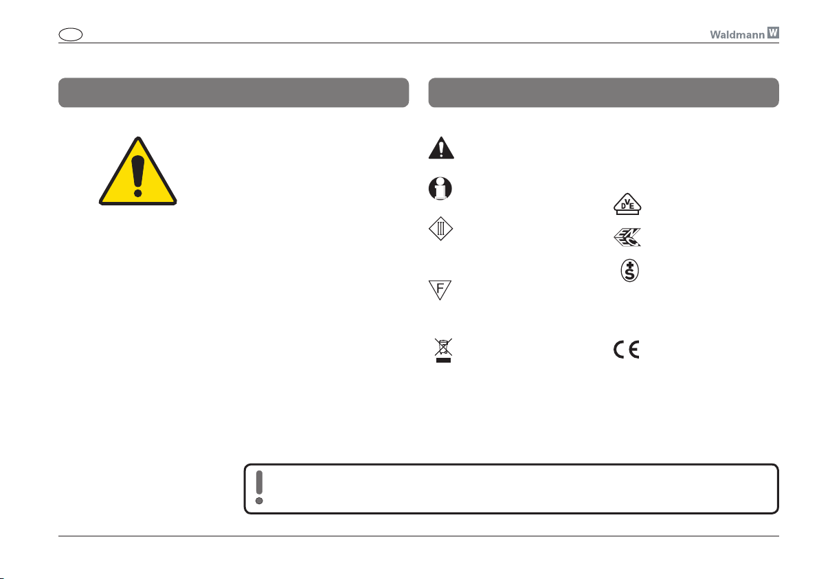
Safety or warning
instructions!
Important information!
Place of use:
Only suitable for rooms not subject
to explosion hazards.
Not for use in the range of action
of high-performance lasers.
Operating mode:
The light is designed for continuous
operation.
The manufacturer cannot be held liable for damage caused by using the unit for purposes contrary
to the designated use or by ignoring safety instructions and warnings.
Unit corresponds to international protection class III
(Operation with savety
extra low voltage (SELV))
The light is suitable for
mounting on normally inflammable surfaces
Observe the disposal
instructions!
LED Light Emitting Diode
VDE Approval
ENEC Approval
SEV Approval
CE
Conformity mark
23
Page 6
GB Instructions for use Machine light ABLL 1
Mounting
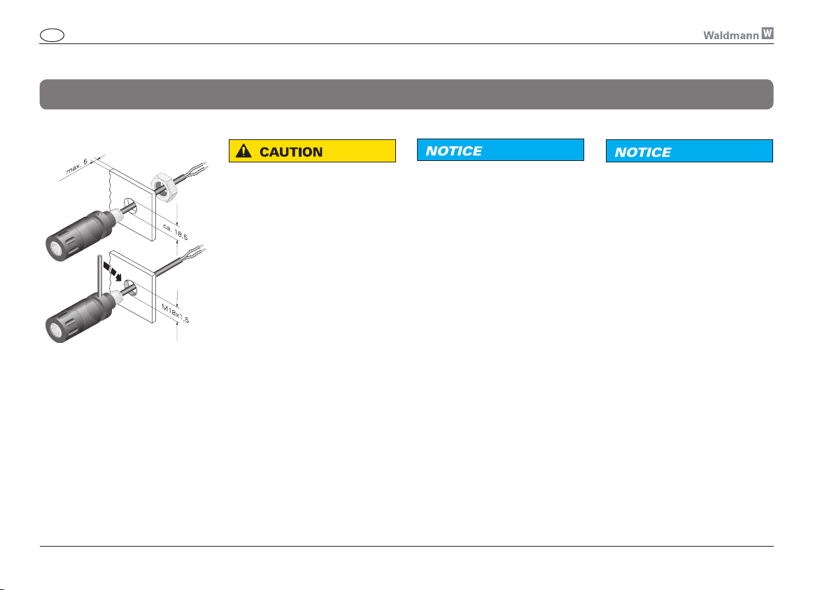
Fig. 12
! CAUTION
Danger due to insufficient fastening!
When mounted incorrectly, the
light may fall down.
¾ Mounting to a surface suitable
for mounting only!
¾ Mounting by a skilled electri-
cian only!
Montage
The light has been designed as
stationary light.
The light can be mounted on a
through hole of approximately
18.5 mm in diameter (using the
enclosed nut) or directly on the
M18 x 1.5 thread (see Fig. 12).
NOTICE
Reduction of the useful life!
With insufficient heat dissipation,
the useful life of the light will
diminish!
¾ Operate the light only when
mounted.
¾ Provide a sufficiently large
metallic mounting area (recommended area of dissipation at
least 20 cm2).
¾ Ensure efficient heat transfer
between the ligh t and the
mounting area.
NOTICE
Damage caused by the incident
laser beam!
Direct or indirect incidence of a
laser beam may result in the destruction of the LED.
¾ Use the light only outside the
range of action of high-performance lasers (e.g. cutting laser,
welding laser).
24
Page 7
GB Instructions for use Machine light ABLL 1
Connection
NOTICE
Damage caused by wrong connection!
Wrong connection may result in
the light being damaged or destroyed.
¾ Operate the light with the ope-
rating units proposed by the
manufacturer only.
¾ Connect the light only when the
operating device is off!
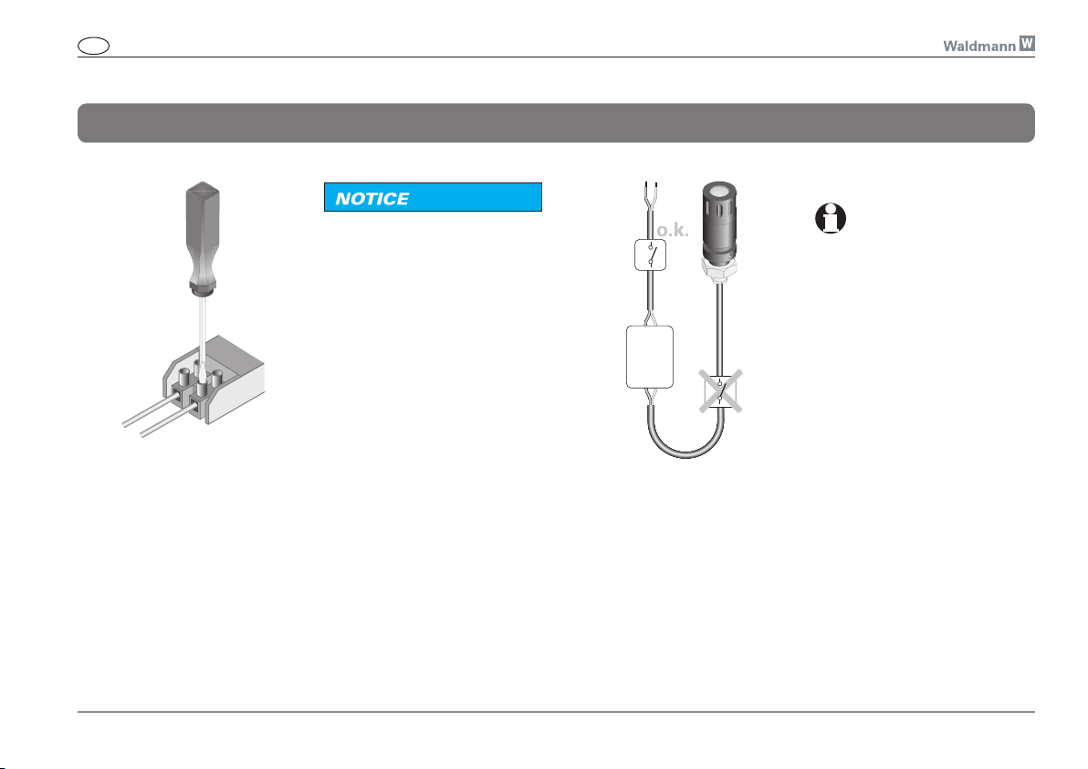
¾ Install the switch always in the
primary electric circuit (see
fig. 14)!
¾ Connection only by a skilled
electrician!
¾ The operating device must be
positioned in accordance with
its type of protection.
Fig. 14
Operating
unit
Connection
Important Information
See connection diagrams on page
31.
Depending on the mains voltage
and the selected operating current, different operating units are
suitable.
Suitable operating units can be
found in the Appendix (page 30).
Connect the light as shown on
page 31.
Two versions of the the Waldmann
operating unit are available, which
have different operating currents.
Note: Higher operating current
means higher light yield and shorter useful life.
25
Page 8
GB Instructions for use Machine light ABLL 1
Operation
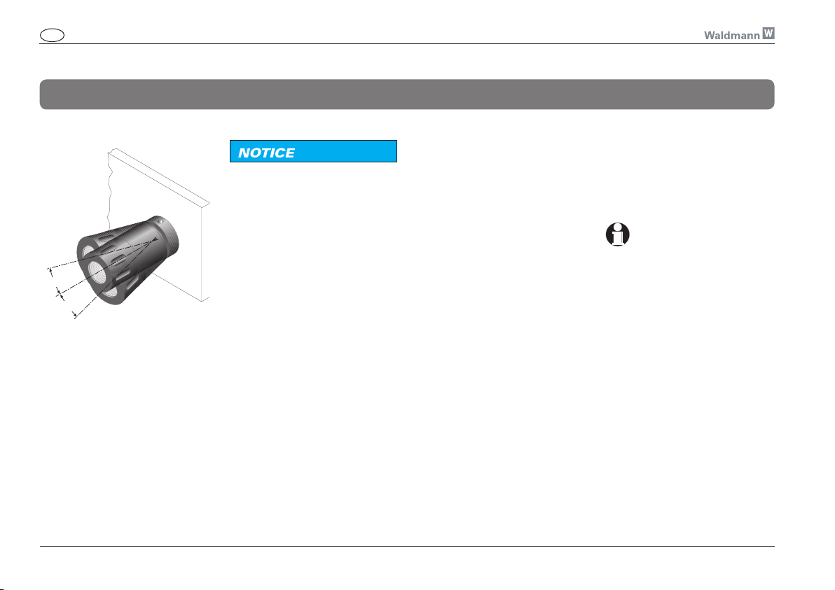
Fig. 15
NOTICE
Damage caused by turning the
light by force!
Turning the light by force will expand the internal spring and reduce
the self-retention of the ball joint.
¾ Do not turn the light axially!
Positioning
The light can be swiveled in any
direction by about 20°.
The light module is held in the set
position by the ball joint. To change
the position, simply swivel the light
module into the desired direction.
Switching ON/OFF
The light is not equipped with
a switch of its own. It is usually switched on/off via external
switching elements.
Important information
Install the switch always in the
primary electric circuit (see fig. 14
on page 25)!
26
Page 9
GB Instructions for use Machine light ABLL 1
Maintenance and repair
! WARNING
Danger due to electrical shock
in case of contact!
Maintenance or repair work carried
out incorrectly may result in serious
injuries or death.
¾ Disconnect the light from the
mains before carrying out any
maintenance or repair work!
¾ Maintenance and repair work
must be carried out by a skilled
electrician only!
¾ Only parts released by the
manufacturer may be used as
spare parts!
Maintenance
The light module ist maintenancefree.
NOTICE
Loss in tightness!
The main parts of the light module
are bonded to each other. When the
two parts are separated from one
another, tightness may get lost.
¾ Do not separate the light parts
from one another!
Defective light source
The light works with one
light emitting diode (LED).
The useful life of LEDs exceeds by
far that of conventional lamps (e.g.
light bulbs). Therefore, a replacement of the light source is rarely
necessary.
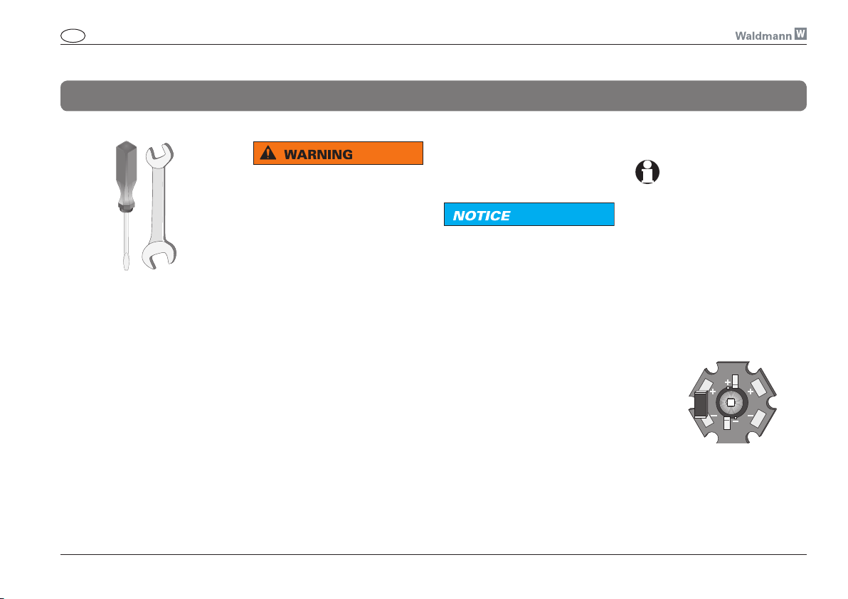
If nevertheless the LED should
break down, the entire LED module
[Fig. 17] must be replaced. To do
so, send the complete light to
the manufacturer.
Fig. 17
27
Page 10
GB Instructions for use Machine light ABLL 1
Care Disposal
28
NOTICE
Risk of damage through wrong
care!
Wrong care may destroy the unit.
¾ Clean the transparent cover at
regular intervals!
¾ Clean the light parts only with
a cloth impregnated with a
suitable household cleaning
agent!
¾ Make sure the agents used
are compatible with paints and
plastics!
NOTICE
Environmental hazard!
Wrong disposal endangers our
environment.
¾ Return the unit at the
end of its useful life to
the available recycling
systems!
Page 11
GB Instructions for use Machine light ABLL 1
Technical data
General:
Protection class III
Protection type IP 67
Operating mode: Continuous
operation
Technical safety check
according to EN 60598-1
Rating according to DIN 60825-1
and VDE 0837 Laser class 1
Dimensions:
Complete approx. Ø 29 x 94 mm
without fastening element:
approx. Ø 29 x 71 mm
Connecting cable
approx. 500 mm
Electrical values:
Operation with Waldmann type A
operating unit or VLM operating
unit type 1
Operating current 700 mA
Power approx. 3.0 W
Useful life * approx. 50,000 h
Operation with Waldmann type C
operating unit or VLM operating
unit type 2
Operating current 350 mA
Power approx. 1.5 W
Useful life ** approx. 50,000 h
* Decrease in luminous flux approx. 70 %
** Decrease in luminous flux approx. 50 %
NOTICE
Risk of damage due to differences from the standard design.
If required, this series of units will
be supplemented by further variants. The technical data may therefore be subject to modifications.
¾ Always observe the data and
symbols given on the rating
plate!
29
Page 12
GB Instructions for use Machine light ABLL 1
Appendix
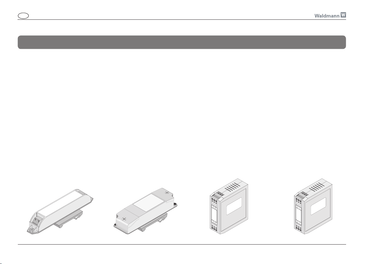
Suitable operating units
For 230 V AC (700 mA)
VLM type 1 operating unit
Order No. 209 585 019
Input voltage 95-240 V
Frequency range 50/60 Hz
Output current 700mA
Assembly:
Adapter plate including clip for
mounting rail
Operating unit/light module line
length max. 10 m
a maximum of 3 light modules
can be connected (in series)
For 230 V AC (350 mA)
VLM type 2 operating unit
Order No. 209 595 019
Input voltage 95-240 V
Frequency range 50/60 Hz
Output current 350mA
Assembly:
Adapter plate including clip for
mounting rail
Operating unit/light module line
length max. 10 m
a maximum of 3 light modules
can be connected (in series)
For 24 V AC/DC (700 mA)
Waldmann-type A operating unit
Order No. 209 582 019
Input voltage 19.2-28.8 V
Frequency range 50/60 Hz / DC
Output current 700 mA
Assembly:
Housing for mounting to mounting rail
Operating unit/light module line
length max. 10 m
a maximum of 3 light modules
can be connected (in series)
For 24 V AC/DC (350 mA)
Waldmann-type C operating unit
Order No. 209 582 039
Input voltage 19.2-28.8 V
Frequency range 50/60 Hz / DC
Output current 350 mA
Assembly:
Housing for mounting to mounting rail
Operating unit/light module line
length max. 10 m
a maximum of 3 light modules
can be connected (in series)
30
Fig. 25bFig. 25a
Fig. 25c Fig. 25d
Page 13
GB Instructions for use Machine light ABLL 1
Appendix
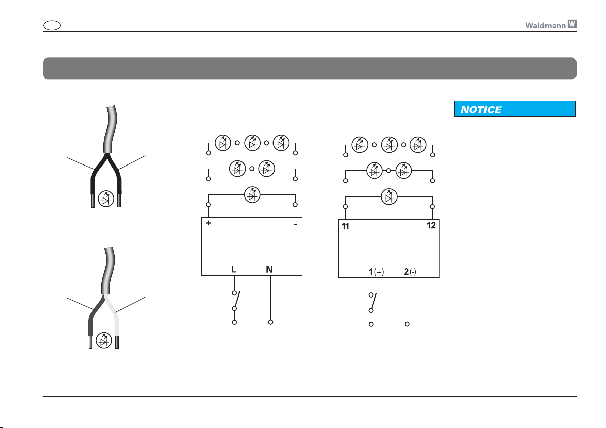
Fig. 26a
1 (+)
Fig. 26b
brown
(+)
2 (_)
white
(_)
Fig. 27
Output
Operating unit
Input
230 V AC
Waldmann operating unitVLM operating unit
Fig. 28
Output
Operating unit
Input
24 V DC
24 V AC
NOTICE
Damage caused by wrong connection!
Wrong connection may result in
the light being damaged or destroyed.
¾ Operate the light only with a
suitable operating unit.
¾ Connect the light only when the
operating device is off!
¾ Install the switch always in the
primary electric circuit (see fig.
14 on page 25)!
¾ Connection only by a skilled
electrician!
31
 Loading...