

WS100/12 Product Manual
Thank you for purchasing Wakespeed Offshore’s Model WS100/12 MultiStage Voltage Regulator. Designed by Michael Frost, one of the pioneers of
smart, multi-stage battery charging systems, the Wakespeed WS100/12
voltage regulator provides optimal care for your batteries, when used in
conjunction with a P-type, externally regulated alternator.
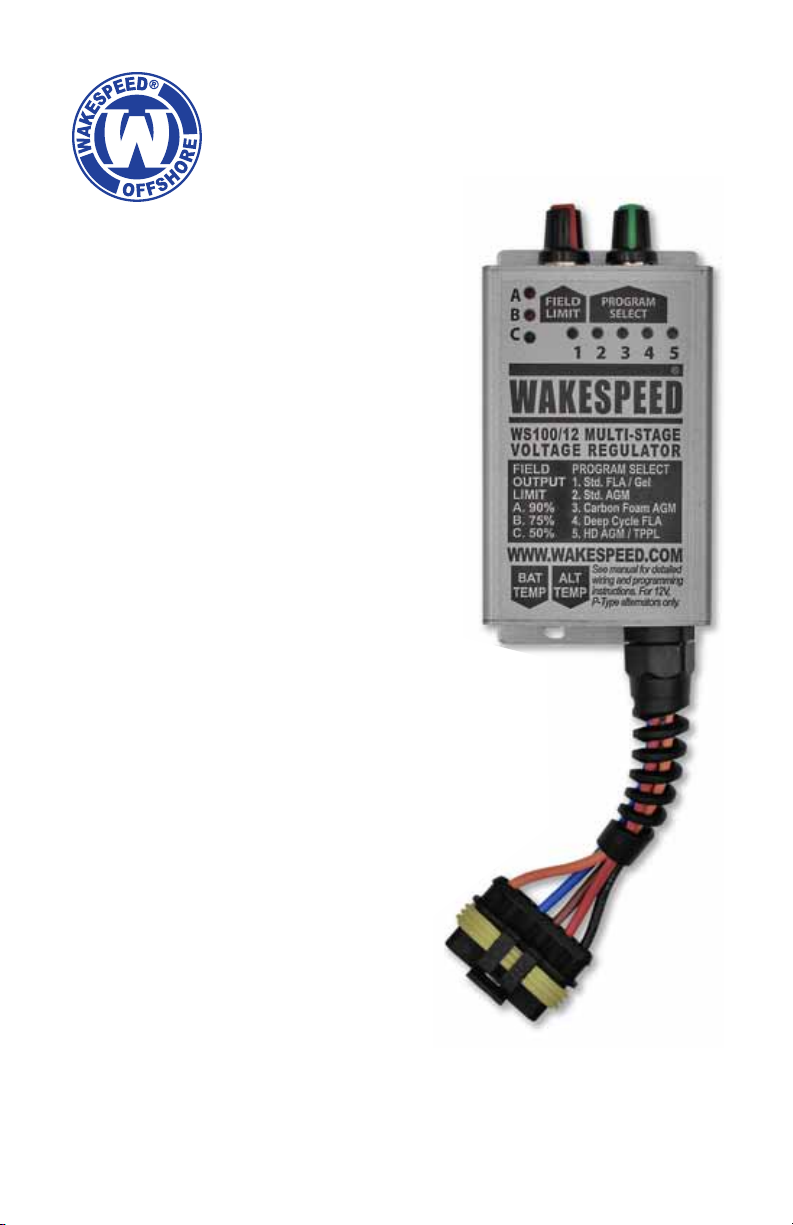
The WS100/12 was designed specically to provide the user with an extremely simple interface — only two adjustments are required to deliver
tailored charging to your batteries. A convenient ve-position rotating
switch enables the user to select one of ve programs based on battery
type: standard ooded/gel, standard AGM, Carbon Foam, deep cycle
ooded and high-density AGM/TPPL.
In addition to the selectable programs for battery type, the WS100/12
provides the ability to adjust the maximum regulator eld output, making
it possible to reduce alternator horsepower load to the engine and belt.
Four settings are available: 100% (no eld reduction), 90%, 75% and
50% eld output.
The WS100/12 can be used alone, or in conjunction with optional WS100-ATS and WS-100-BTS alternator and battery temperature sensors.
With the temperature sensors installed, the WS100/12 can monitor and
respond to changes in ambient battery temperatures and reduce charging
output if the alternator temperature exceeds safe operating temperatures.
Page 1
WS100/12 Product Manual
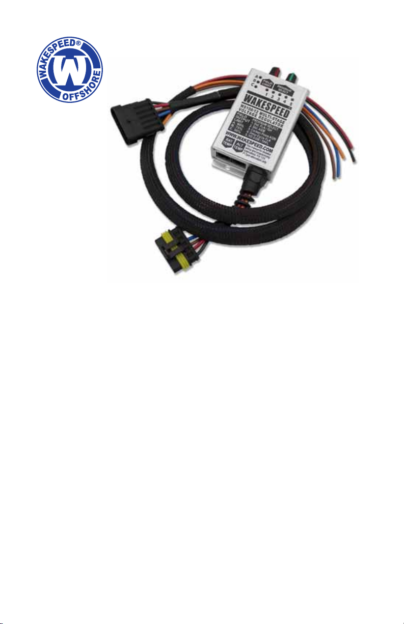
REGULATOR WIRING
The Wakespeed WS100/12 is provided with
a 5-wire harness, which provides wiring
connections required for proper voltage
regulator operation. Wires include Red
(Power), Black (Ground), Blue (Field), Brown
(Ignition) and Orange (Dash Lamp). Wiring
identication and suggested mounting
locations are as follows:
RED (POWER) WIRE —
The WS100/12 Power Wire provides DC
current to support regulator functions
and to provide eld current to control
alternator excitation (eld) output – as well
as providing the regulator with sensing
voltage. The Power Wire must be fused at
10 amps. An ATC-type fuse holder and 10A
ATC fuse are included with the regulator, and
must be installed at the source of power (at the
alternator or battery end of the wiring harness).
Possible connection locations for the RED
Power Wire include:
1. The positive output post of the alternator
(recommended).
2. The positive post of the battery being
charged.
3. If a diode-type battery isolator is
used, the RED power wire must be
installed on the output side of the
isolator, on the post connected to
the larger battery bank.
Regulator Wiring
Page 2

WS100/12 Product Manual
Regulator Wiring
BLACK (GROUND) WIRE —
The WS100/12 Ground Wire provides a connection between the voltage
regulator and system ground. Possible connection locations for the
BLACK Ground Wire include:
1. The ground post of the alternator (recommended).
2. The ground post of the battery being charged.
BROWN (IGNITION) WIRE —
The WS100/12 Ignition Wire provides a switched source of DC system
voltage which acts as the ON/OFF switch for the voltage regulator.
Possible connection locations for the BROWN Ignition Wire include:
1. The ON side of the vessel’s ignition switch. In most cases, a switched
source of ignition voltage will already be established at your engine’s
alternator. Refer to your engine manual to identify your alternator’s
ignition wire. The wire should provide zero volts when the ignition
is off and the engine is not running, and system voltage whenthe
ignition switch is on and the engine is running (recommended).
2. The ON side of an oil pressure switch.
BLUE (FIELD) WIRE —
The BLUE eld wire in the regulator’s wiring harness provides eld current
to the alternator’s positive brush, which enables the regulator to control
excitation and alternator output. The BLUE eld wire is connected to the
eld terminal of an externally regulated P-type alternator.
If your alternator is not designed for external voltage regulation (i.e., an
internally-regulated alternator) it will be necessary to modify the alternator
to provide access to the alternator’s positive brush.
In some cases, this will require that the alternator must be opened up
to disable the internal regulator and diode trio, and a direct pathway be
created between the positive brush and a terminal on the outside of the
alternator that’s isolated from the alternator’s grounded frame. This can
be a difcult process.
We strongly recommend using a qualied alternator shop for any alternator
modications, including conversion to external regulation.
Page 3
WS100/12 Product Manual
Regulator Wiring
ORANGE (DASH LAMP) WIRE —
The ORANGE Dash Lamp circuit is designed to provide a source of
ground to complete a circuit at a warning light or audible alarm if one
of the following conditions exists: low system voltage (alternator is not
charging properly), high system voltage (alternator is charging above safe
voltage), high alternator temperature (requires alternator temperature
sensor), high battery temperature (potential thermal runaway at batteries).
The Dash Lamp wire can be connected to the negative (ground) side of a
user-installed warning lamp or audible alarm.
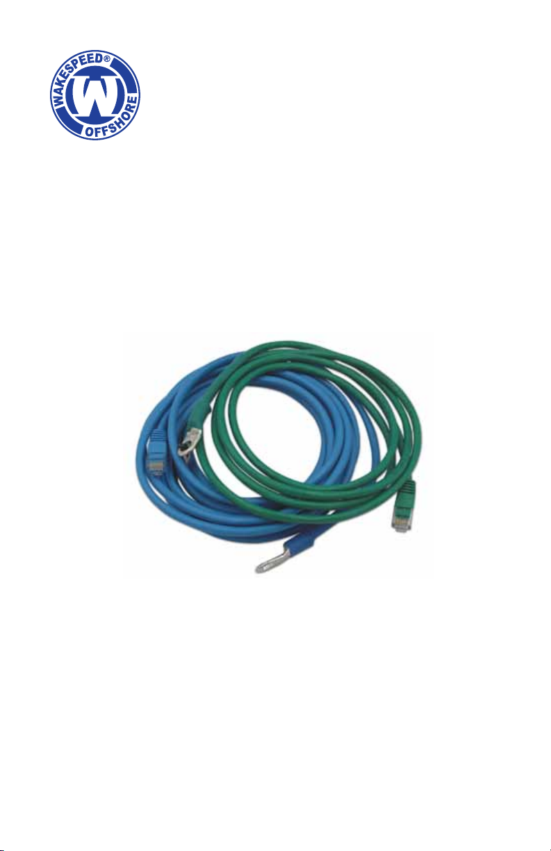
OPTIONAL TEMPERATURE SENSOR CABLES
When used in conjunction with its optional temperature sensor cables,
the WS100 can use ambient temperatures at the batteries and at the
alternator to provide additional safety and charging efciency. Connection
for temperature sensor cables is provided via built-in RJ45 terminals at
the bottom of the regulator.
WS100-BTS-KIT — Battery Temperature Sensor Cable (BLUE)
WS100-ATS-KIT — Alternator Temperature Sensor Cable (GREEN)
Page 4
 Loading...