

DeltaFireTM 500
User’s Guide

WaiLAN Communications, Inc.
DeltaFire 500 User’s Guide
Version: V1.0
Part Number: 311-090001
Copyright © 1998 WaiLAN Communications, Inc.
Address: WaiLAN Communications, Inc.
2032 Bering Drive
San Jose, CA 95131
Phone: 408.452.8081
Fax: 408.452.8381
URL: www.wailan.com
Notice:
AGATE™ and DeltaFire are trademarks of WaiLAN Communications, Inc. All other company
or product names mentioned are the property of their respective owners. All rights reserved.

DeltaFire 500 User’s Guide
FEDERAL COMMUNICATIONS COMMISSION (FCC) STATEMENT -- PENDING
This equipment has been tested and found to comply with the limits for a Class A Digital Device pursuant to Part 15
of the FCC rules. These limits are designed to provide reasonable protection against interference if installed and
operated properly in a commercial environment. This equipment generates, uses, and can radiate radio frequency
energy and if not properly installed and used in accordance with the instructions in this manual, may cause harmful
interference to radio communications. Operation of this equipment in a residential area is likely to cause harmful
interference in which case the user will be required to correct the interference at his own expense.
However, there is no guarantee that interference will not occur in a particular installation. If this equipment does
cause harmful interference to radio or television reception, which can be determined by turning the equipment off
and on, the user is encouraged to try and correct the interference by one or more of the following measures:
• Reorient or relocate the receiving antenna.
• Increase the separation between the equipment and receiver.
• Connect the equipment into an outlet on a circuit different from that to which the receiver is connected.
• Consult the dealer or an experienced radio/TV technician for help.
WARNING! In order to meet FCC emission limits and to prevent interference to nearby radio and
television reception, it is essential that only the supplied AC power adapter be used.
SAFETY PRECAUTION
Before attempting to set up or operate your DeltaFire device, please read the following precautions carefully.
1. Immediately upon unpacking the DeltaFire device, inspect for external damage. If the unit has been damaged in
any way, do not attempt to operate it and return it immediately to WaiLAN Communications, Inc. Do not
connect the AC power adapter to an AC power source if the cord or the plug of the adapter is frayed or split.
2. Do not open the case. There are no user serviceable parts within.
3. Do not attempt to use any other similar AC power adapter rather than the one supplied with the package.
4. The supplied AC power adapter is designed exclusively for operation at 100V~120V, 60Hz AC, unless
otherwise specified.. Before inserting the AC power plug into a wall socket, be certain that your electrical power
is within the correct range of values.
5. Do not operate the DeltaFire device beyond the temperature and humidity range specified (see specifications
section).
6. Do not place near or over sources of heat such as a heater or radiator. Do not expose this unit to rain or
moisture.
7. Do not allow objects or foreign substances to enter the unit. If the unit malfunctions, immediately turn off the
power by removing the power plug from the outlet.
Note: Every effort has been made to make this user’s guide as complete and accurate as possible, but no
warranty or fitness is implied. The information is provided on an “as is” basis. WaiLAN
Communications, Inc. shall have neither liability nor responsibility to any person or entity, with respect to
any loss or damage arising from the information contained in this user’s guide or the use of the product
itself.
311-090001 © 1999 WaiLAN Communications, Inc. Page 1

DeltaFire 500 User’s Guide
TABLE OF CONTENTS
INTRODUCTION................................................................................................................................................ 3
PRODUCT DESCRIPTION................................................................................................................................3
INSTALLATION.................................................................................................................................................4
Connections ............................................................................................................................................. 4
LED Indicators.........................................................................................................................................4
Telephone Wire Requirements..................................................................................................................5
Installation Diagram.................................................................................................................................5
SYSTEM MANAGEMENT.................................................................................................................................6
Accessing System ..................................................................................................................................... 6
Console....................................................................................................................................................6
Telnet....................................................................................................................................................... 6
CONFIGURATIONS & MONITORING............................................................................................................ 6
Main Menu...............................................................................................................................................6
Default Password...................................................................................................................................... 7
System Information.................................................................................................................................. 7
Traffic Statistics ....................................................................................................................................... 8
Virtual LAN (VLAN) Configuration......................................................................................................... 8
Port Configuration .................................................................................................................................... 9
IP Range Table.......................................................................................................................................10
Static Routing Table............................................................................................................................... 10
SNMP Configuration .............................................................................................................................. 11
Change Password ................................................................................................................................... 12
Reset...................................................................................................................................................... 12
Software Upgrade................................................................................................................................... 12
SNMP Support....................................................................................................................................... 13
TROUBLESHOOTING.....................................................................................................................................18
Table 1: Troubleshooting Procedures ..................................................................................................... 18
APPENDIX A TECHNICAL SPECIFICATIONS ............................................................................................ 19
Table 2: Technical Specifications........................................................................................................... 19
Table 3: MSDSL Line Card Rate at Different Cable Lengths................................................................... 19
Table 4: RADSL Line Card Rate at Different Cable Lengths................................................................... 20
APPENDIX B PORT PIN LAYOUTS ............................................................................................................... 21
Table 5: 6-Port DSL Pin Layout (50-pin Centronics)............................................................................... 21
Table 6: Console Port Pin Layout (RS-232)............................................................................................. 22
Table 7: 10/100Base-T Port RJ-45 Pin Layout......................................................................................... 22
User’s Reference Form........................................................................................................................... 23
Technical Support Information ............................................................................................................... 26
311-090001 © 1999 WaiLAN Communications, Inc. Page 2

DeltaFire 500 User’s Guide
INTRODUCTION
Thank you for purchasing these outstanding WaiLAN communication products. This user’s guide
describes how to operate your new DSL Access Switch.
Instructions for installing your DeltaFire device(s) are described in the Installation section, while the
remaining sections review operation of the DeltaFire device(s) after they are installed, such as self-test,
LED indication, and troubleshooting.
PRODUCT DESCRIPTION
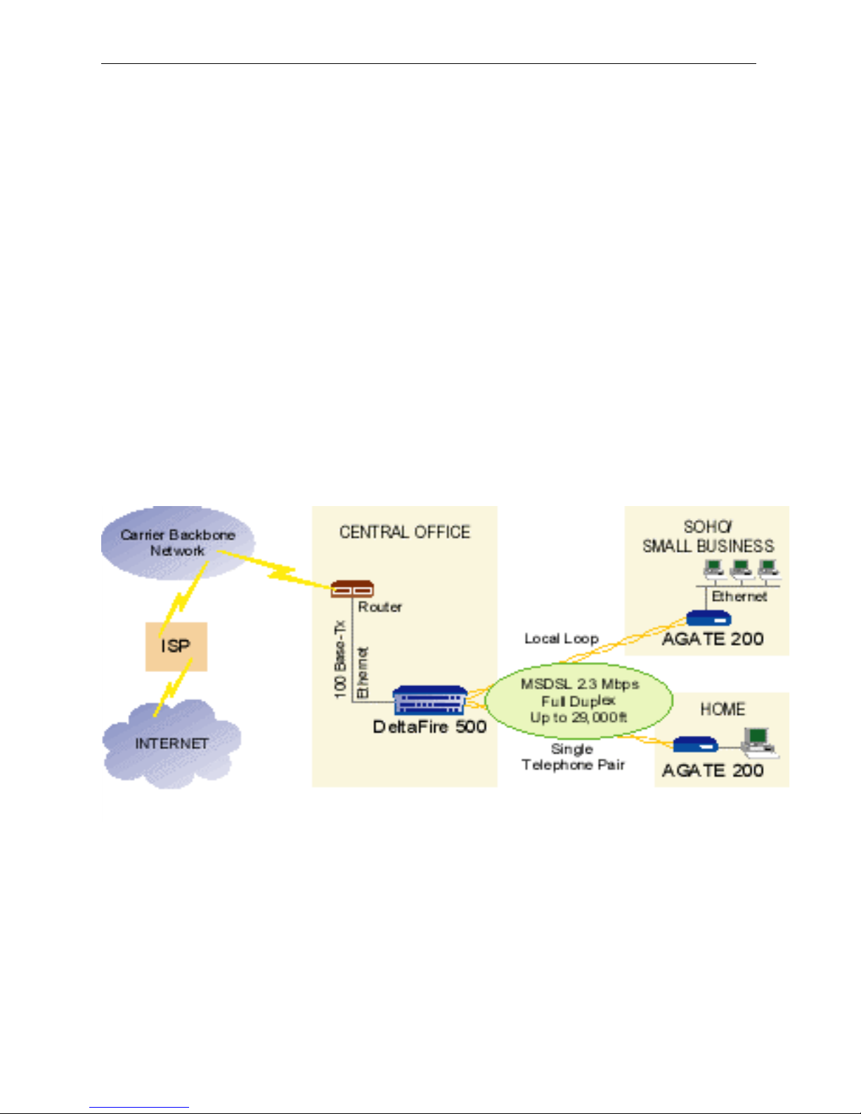
DeltaFire 500 is the industry’s first xDSL access switch router, which combines LAN switching, IP
routing and high-speed xDSL technologies. It is truly a high-speed remote LAN/WAN access device
utilizing RADSL WaiDSL, RADSL and MSDSL.
DeltaFire 500, working in conjunction with the company’s AGATE product line, provides remote
connections for LANs or workstations over regular copper telephone pairs with speeds up to 7 Mbps full
duplex and up to 2.3 Mbps for MSDSL, depending on line quality and distance. The remote LANs or
workstations can be located up to 29,000 feet away.
DeltaFire 500’s chassis is a 5-slot chassis with a dual redundant, load-balancing, hot-swappable plug-in
power supply. The Main Controller Board occupies the bottom slot while the remaining four slots allow
hot-swappable plug-in line cards for different line encoding technologies such as RADSL or MSDSL.
The line card plug-in cards can be mixed.
Features
• Layer-2 access switch for 24 xDSL ports plus Ethernet port; transparent to upper layer protocols
• Static and dynamic IP routing on all DSL and Ethernet ports
• Port-based Virtual LAN (VLAN) with support for up to 8 groups
• Simultaneous VLAN switching and routing
• Holds up to 4 mixed line cards: MSDSL, RADSL, WaiDSL or other xDSL technologies
• Hot-swappable multi-port xDSL line cards
• Bandwidth control on each xDSL port
• Data transport to/from the Internet via 10/100Base-T auto sensing Ethernet Port
• Completely secured communication with individual private line connections
• Compact 5-slot chassis has a plug-in fan module, dual hot-swappable power supplies with load
balancing and full redundancy
• Flash memory for system software upgrade through TFTP
• Centralized network management: SNMP embedded agent and support for standard MIB-II and
WaiLAN private MIB
• Supports VT-100 terminal emulation and telnet for network configuration and monitoring
• Protocols supported: TCP/IP, telnet, ping, tftp, ARP, SNMP, RIP-1, RIP-2
311-090001 © 1999 WaiLAN Communications, Inc. Page 3
DeltaFire 500 User’s Guide
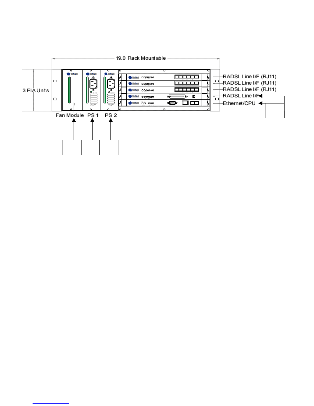
INSTALLATION
(4)
(1) (2) (3)
Connections
(5)
(1) Fan Module
(2) Power Supply 1
(3) Power Supply 2 (optional)
(4) Control Card:
Console Port, RS-232 (DB-9 Female Connector): Console serial port for system configuration
LAN Network Port: Standard 10/100Base-T Ethernet interface port (RJ-45 Jack)
Fiber-Optic I/F (optional plug-in module)
(5) Line Card:
Standard 50-pin Telco connector (optional 6 port, RJ-11, harmonica)
LED Indicators
Power Supply: Power OK – Green LED, on during normal operation
Control Card: PWR – Red LED, on when power failure occurs
SYS – Green LED, on when system failure occurs
RUN – Yellow LED, blinks with normal operation
100M – Yellow LED, on when 100Base-T plugged into LAN port
RX/TX – Yellow LED, on/blinking when 10/100Base-T plugged in/activity
Line Card: Ports 1-6 – Yellow LED, on/blinking when port is linked/activity
311-090001 © 1999 WaiLAN Communications, Inc. Page 4
DeltaFire 500 User’s Guide
Telephone Wire Requirements
The telephone circuits recommended for the DeltaFire are commonly known as Dry Line, Dry Pair, Raw
Copper Line, or Alarm Circuit. Now, it is often referred as DSL Line or ADSL Line.
When ordering a DSL line from a Telco, make sure to tell the telephone company that you need a line
with no load coils or bridge taps on it. For example, Pacific Bell’s Local Area Data Channels (LADC) use
USOC code to specify a 2-wire dry line as “T6E2D”.
NOTE:
The term “non-loaded” or “non-loaded coils” means no passive lowpass filter for voice spectrum on the
line. With a lowpass filter, the loop is used for voice signal only, the high frequency spectrum of signals
(above 4Khz) will be filtered out, and the loop cannot be used for xDSL signal transmission.
To have the dry line from a Telco, the loaded coils in the Telco’s Central Office and bridge taps at punch
down blocks MUST BE REMOVED from the subscribed line.
Installation Diagram
311-090001 © 1999 WaiLAN Communications, Inc. Page 5

DeltaFire 500 User’s Guide
Console Management, Version DeltaFire 1.0 Beta (Feb 15 1999)
SYSTEM MANAGEMENT
Accessing System
Access to the System Management Main Menu can be gained either through a Console Port or LAN Port
(Telnet):
• CONSOLE PORT – The console port is located on the Controller Card of the DeltaFire. Console
connection is through an RS-232 DB-9 male cable to the terminal/computer’s serial COM 1 or COM
2 port. Users may choose to use any terminal emulation software (PROCOMM Plus is
recommended).
COM Port Configuration for direct connection to Console Port:
Terminal Emulation: VT-100
Speed : 9600, 14,400, 19,200, 28,800, 38,400, 57,600 or 115,200
Data Bit : 8
Parity Bit : None
Stop Bit : 1
• TELNET – Once the IP Address is assigned to the DeltaFire device, users can telnet to the DeltaFire
device for system configuration. An appropriate IP address for the user’s network must be configured
by a console terminal before the telnet command can be used.
CONFIGURATIONS & MONITORING
Main Menu
After making a connection to the DeltaFire device press <Enter> a few times to see the screen below.
Select the desired function by entering the corresponding number.
Copyright (C) 1998-1999, WaiLAN Communications, Inc.
Main Menu
1. System Information
2. Traffic Statistics
3. VLAN Configuration
4. Port Configuration
5. IP Range Table
6. Static Routing Table
7. SNMP Configuration
8. Password Change
9. Reset
0. Exit
Tab : Move to next changable field
Up/down Arrow : Move cursor by one line
Left/right Arrow: Move cursor by one character
Space/enter : Next choice when in selection field
311-090001 © 1999 WaiLAN Communications, Inc. Page 6

DeltaFire 500 User’s Guide
Please Enter Password :
Default Password
When you try to access a Sub-menu, the DeltaFire device will prompt you to enter the password by
displaying the following screen.
The password is required in order to access the System Management Sub-menus. You will need to reenter the password each time the device is restarted, reset or left idle for several minutes. The default
password is set to “wailan”. You may change the password in the main menu.
Press Esc to return to the main menu:
System Information
- The first line of System Information sub-menu shows the system name. This is for users to identify
the DeltaFire devices.
- The next line shows the Security Level.
- The following line displays if TFTP download is enabled. You can change this by pressing <y/n> or
<Enter>. You must press <Ctrl-s> and then press <Enter> to save the changes.
- The Ethernet Address is for the Controller Card fast Ethernet port.
- The next three lines display the currently assigned IP Address, Subnet Mask and Default Gateway.
These values should be changed to fit into the user’s network in which the DeltaFire will be deployed.
- The Microprocessor line shows the CPU type on the Controller Board and the serial number of the
Board in on the following line.
- The tenth and eleventh lines display the Hardware Revision and Software Version. (You should
check the WaiLAN Web site (www.wailan.com) to see if the software is the latest version; if not, you
should upgrade your software.)
- The last four lines notify the user of the current ROM, RAM size, the baud rate of the serial port and
the current speed of the fast Ethernet port.
(NOTE: ALL CHANGES SHOULD BE SAVED BY PRESSING <CTRL-S> FOLLOWED BY PRESSING <ENTER>.
EXAMPLE OF SUB-MENU #1: SYSTEM INFORMATION
===== System Information =====
. System Name : DeltaFire A
. Security Level : High
. Allow TFTP Download : N
. Ethernet Address : 00 E0 F3 FF 34 98
. IP Address (Ethernet port) : 192.168. 0.170
. Subnet Mask : 255.255.255. 0
. Default Gateway : 0. 0. 0. 0
. Microprocessor : R4640 CPU 200MHz
. Serial Number : 00000321AF8B
. Hardware Revision : Rev.D
. Software Version : DeltaFire 1.0 Beta (Feb 15 1999)
. ROM Size : 4194304
. RAM Size : 16777216
. Serial Port Baud Rate : 38400
. Ethernet Current Speed : 10Mbps
311-090001 © 1999 WaiLAN Communications, Inc. Page 7

DeltaFire 500 User’s Guide
Traffic Statistics
The Statistics sub-menu 2 provides traffic statistics from/to the Ethernet port and from/to DSL ports
- RX: Number of packets received
- TX: Number of packets transmitted
- ERR: Number of errors while receiving
Note: The 6-port line cards are counted from top to bottom, i.e. the top card is Slot 1.
===== Traffic Statistics =====
Ethernet Port: RX 10 TX 18 ERR 0
|Slot1|---Port1---|---Port2---|---Port3---|---Port4---|---Port5---|---Port6---|
| RX | 0 | 0 | 341 | 0 | 0 | 0 |
| TX | 0 | 0 | 20 | 0 | 0 | 0 |
| ERR | 0 | 0 | 0 | 0 | 0 | 0 |
|Slot2|-----------|-----------|-----------|-----------|-----------|-----------|
| RX | 0 | 0 | 0 | 0 | 0 | 0 |
| TX | 0 | 0 | 0 | 0 | 0 | 0 |
| ERR | 0 | 0 | 0 | 0 | 0 | 0 |
|Slot3|-----------|-----------|-----------|-----------|-----------|-----------|
| RX | 0 | 0 | 0 | 0 | 0 | 0 |
| TX | 0 | 0 | 0 | 0 | 0 | 8 |
| ERR | 0 | 0 | 0 | 0 | 0 | 0 |
|Slot4|-----------|-----------|-----------|-----------|-----------|-----------|
| RX | 0 | 0 | 0 | 0 | 0 | 0 |
| TX | 0 | 0 | 0 | 0 | 0 | 0 |
| ERR | 0 | 0 | 0 | 0 | 0 | 0 |
|-----|-----------|-----------|-----------|-----------|-----------|-----------|
0 Clear to zero - Use -- border Esc Return to the main menu
Virtual LAN (VLAN) Configuration
The VLAN Configuration Sub-Menu 3 displays VLANs grouping configuration. The maximum number
of VLANs possible is eight. The “X” signifies that a port is part of that VLAN. “ETH” means fast
Ethernet port. The user can change the name and configuration of the VLAN.
- To change the name just type in the new name in the appropriate VLAN No. column and press <Ctrl-
s> and <Enter>
- To change the configuration of the VLAN the user must press the <Space Bar> on the appropriate
parts to add or remove an “X” and then press <Ctrl-s> and <Enter> to save
- Note: No changes will be saved if the user does not press <Ctrl-s> and then <Enter>
===== VLAN Configuration =====
Slot1 Slot2 Slot3 Slot4
No. VLAN Name ETH 1 2 3 4 5 6 1 2 3 4 5 6 1 2 3 4 5 6 1 2 3 4 5 6
1 vlan1 X X X X X X X X X X X X X X X X X X X X X X
2 vlan2 X X X
3
4
5
6
7
8
Press Esc to return to the main menu:
311-090001 © 1999 WaiLAN Communications, Inc. Page 8

DeltaFire 500 User’s Guide
Port Configuration
The Port Configuration Sub-Menu 4 is used to configure the individual DSL ports. The port name and the
administration can be assigned. The type of card, DFLC200 MSDSL or DFLC700 RADSL, the speed and
the operating status are automatically detected. If the operating status is UP, that means that that port is
linked. The speed of the link is currently set by the remote AGATE’s line configuration.
NOTE: Press <Ctrl-s> and then <Enter> to save any changes made.
===== Port Configuration =====
Speed InBw OutBw
|-Slot|Port|-Type----|--Port Name--|-(kbps)|-AdmSta-|-OpSta-|(kbps)|(kbps)-|
| 1 | 1 | DFLC700 | | 0 | ON | DOWN | 0 | 0 |
| 1 | 2 | DFLC700 | | 0 | ON | DOWN | 0 | 0 |
| 1 | 3 | DFLC700 | | 4480 | ON | UP | 0 | 0 |
| 1 | 4 | DFLC700 | | 0 | ON | DOWN | 0 | 0 |
| 1 | 5 | DFLC700 | | 0 | ON | DOWN | 0 | 0 |
| 1 | 6 | DFLC700 | | 0 | ON | DOWN | 0 | 0 |
| 2 | 1 | DFLC200 | | 0 | ON | DOWN | 0 | 0 |
| 2 | 2 | DFLC200 | | 0 | ON | DOWN | 0 | 0 |
| 2 | 3 | DFLC200 | | 0 | ON | DOWN | 0 | 0 |
| 2 | 4 | DFLC200 | | 0 | ON | DOWN | 0 | 0 |
| 2 | 5 | DFLC200 | | 0 | ON | DOWN | 0 | 0 |
| 2 | 6 | DFLC200 | | 0 | ON | DOWN | 0 | 0 |
|-----|----|---------|-------------|-------|--------|-------|------|-------|
Use Up/Down Arrows to Scroll the Table.
Ctrl-s Save all - Use -- border Esc Return to the main menu
IP Range Table
The IP Range Table Sub-Menu 5 allows the user to assign a name to a DSL port, give that port a Network
ID (IP address) and assign the Subnet Mask for that port. RIP can be enabled or disabled as well. The user
can choose what Slot no. (line card) and what port on that line card to change. The screen also displays
what VLAN group, if any, the particular port belongs to (this can not be changed here). Note: All
changes require that the user press <Ctrl-s> and then <Enter>.
===== IP Range Table =====
RIP VLAN Gps
|-Slot|Port|--Port Name--|---Network ID---|---Subnet Mask--|Enabled|-12345678-|
| 1 | 1 | | 0. 0. 0. 0| 0. 0. 0. 0| N | X |
| 1 | 2 | | 0. 0. 0. 0| 0. 0. 0. 0| N | X |
| 1 | 3 | | 0. 0. 0. 0| 0. 0. 0. 0| N | X |
| 1 | 4 | | 0. 0. 0. 0| 0. 0. 0. 0| N | X |
| 1 | 5 | | 0. 0. 0. 0| 0. 0. 0. 0| N | X |
| 1 | 6 | | 0. 0. 0. 0| 0. 0. 0. 0| N | X |
| 2 | 1 | | 0. 0. 0. 0| 0. 0. 0. 0| N | X |
| 2 | 2 | | 0. 0. 0. 0| 0. 0. 0. 0| N | X |
| 2 | 3 | | 0. 0. 0. 0| 0. 0. 0. 0| N | X |
| 2 | 4 | | 0. 0. 0. 0| 0. 0. 0. 0| N | X |
| 2 | 5 | | 0. 0. 0. 0| 0. 0. 0. 0| N | X |
| 2 | 6 | | 0. 0. 0. 0| 0. 0. 0. 0| N | X |
|Total 24--|-------------|----------------|----------------|-------|-12345678-|
Use Up/Down Arrows to Scroll the Table.
Ctrl-s Save all - Use -- border Esc Return to the main menu
311-090001 © 1999 WaiLAN Communications, Inc. Page 9

DeltaFire 500 User’s Guide
Static Routing Table
The Static Routing Table Sub-Menu 6 allows the user to configure a network that is not directly
connected to DeltaFire ports. The Slot number (line card) and port number specifies that port that
connects to the network. The Network ID and a Subnet Mask specify the IP network and the Next Hop is
the default gateway from which the packets can pass through. The Metric specifies the cost to that
network..
Note: All changes require that the user press <Ctrl-s> and then <Enter>.
===== Static Routing Table =====
|Slot|Port----Network ID---|---Subnet Mask---|----Next Hop-----|-Metric-|
| 0 | 0 | 0. 0. 0. 0 | 0. 0. 0. 0 | 0. 0. 0. 0 | 0 |
| 0 | 0 | 0. 0. 0. 0 | 0. 0. 0. 0 | 0. 0. 0. 0 | 0 |
| 0 | 0 | 0. 0. 0. 0 | 0. 0. 0. 0 | 0. 0. 0. 0 | 0 |
| 0 | 0 | 0. 0. 0. 0 | 0. 0. 0. 0 | 0. 0. 0. 0 | 0 |
| 0 | 0 | 0. 0. 0. 0 | 0. 0. 0. 0 | 0. 0. 0. 0 | 0 |
| 0 | 0 | 0. 0. 0. 0 | 0. 0. 0. 0 | 0. 0. 0. 0 | 0 |
| 0 | 0 | 0. 0. 0. 0 | 0. 0. 0. 0 | 0. 0. 0. 0 | 0 |
| 0 | 0 | 0. 0. 0. 0 | 0. 0. 0. 0 | 0. 0. 0. 0 | 0 |
| 0 | 0 | 0. 0. 0. 0 | 0. 0. 0. 0 | 0. 0. 0. 0 | 0 |
| 0 | 0 | 0. 0. 0. 0 | 0. 0. 0. 0 | 0. 0. 0. 0 | 0 |
| 0 | 0 | 0. 0. 0. 0 | 0. 0. 0. 0 | 0. 0. 0. 0 | 0 |
| 0 | 0 | 0. 0. 0. 0 | 0. 0. 0. 0 | 0. 0. 0. 0 | 0 |
|Total 32|-----------------|-----------------|-----------------|--------|
Use Up/Down Arrows to Scroll the Table.
Ctrl-s Save all - Use -- border Esc Return to the main menu
SNMP Configuration
The SNMP Configuration Sub-Menu 7 allows the user to assign names to the various SNMP
configurations. To add or remove from a table the user must press <Enter> while the cursor is in front of
the table they want to access. For additional information on SNMP refer to the SNMP Support section.
Note: All changes require that the user press <Ctrl-s> and then <Enter>.
===== SNMP Configuration =====
. Limit Access to SNMP Hosts: N
. Communities (16 bytes max.)
|---------|----Community----|------Read-------|------Write------|
| 1 |public | Y | N |
| 2 | | N | N |
| 3 | | N | N |
|Total 1--|-----------------|-----------------|-----------------|
. SNMP Management Hosts
|---------|----Host Name----|----Community----|-------IP--------|
| 1 | | | 0. 0. 0. 0 |
| 2 | | | 0. 0. 0. 0 |
| 3 | | | 0. 0. 0. 0 |
|Total 0--|-----------------|-----------------|-----------------|
. Trap Destinations
|---------|----Host Name----|----Community----|-------IP--------|
| 1 | | | 0. 0. 0. 0 |
| 2 | | | 0. 0. 0. 0 |
| 3 | | | 0. 0. 0. 0 |
|Total 0--|-----------------|-----------------|-----------------|
Ctrl-s Save all - Use -- border Esc Return to the main menu
311-090001 © 1999 WaiLAN Communications, Inc. Page 10

DeltaFire 500 User’s Guide
Password Change
The Password Change Sub-Menu allows you to change the password. The new password can be up to 15
characters.
===== Password Change =====
Enter New Password :
Password cannot be longer than 15 characters!
Press Esc to return to the main menu:
Reset
For a soft reboot press <y>, and the system will reboot.
===== Reset =====
Are you sure you want to reset the system?(y/n):
Press Esc to return to the main menu:
Software Upgrade
• Trivial File Transfer Protocol (tftp) Download
Have the new software ready and know the file location. Make sure you have the tftp command file in
your system. You can download the tftp DOS Version from WaiLAN’s Web site (www.wailan.com)
under SUPPORT. Enter the following command at a PC DOS prompt (if you use tftp DOS Version) or at
your normal tftp environment: (the firmware file should be in the current directory):
tftp -i [DeltaFire’s IP Address] put [download_filename]
SNMP Support
The DeltaFire devices support the industry-standard Simple Network Management Protocol (SNMP).
This protocol allows users running popular network management software (such as HP’s OpenView and
Castle Rock’s SNMPc) to manage and monitor the DeltaFire devices. The section below describes how to
configure your DeltaFire devices to support SNMP.
Note: This document assumes you know how to use SNMP network management software and how to
configure hosts and set up communities under SNMP. For information about SNMP, you can consult
some reference information about this subject. Below is information about a few good reference books
about SNMP:
SNMP, SNMPv2, and RMON, written by Williams Stallings, published by Addison Wesley
Understanding SNMP MIBs, written by David Perkins and Evan McGinnis, published by Prentice
Hall
Managing Internetworks with SNMP, written by Mark A. Miller, published by M&T books
You can also find frequently asked questions and technical information regarding SNMP at the
following University of Twente Web site: http://snmp.cs.utwente.nl/
311-090001 © 1999 WaiLAN Communications, Inc. Page 11

DeltaFire 500 User’s Guide
Note: WaiLAN provides information about Web sites to assist our customers in obtaining potentially
useful information. WaiLAN is not affiliated with these Web sites and is not responsible for their content
or any changes to their URLs.
Installing the DeltaFire Software MIB Files
To use your SNMP management software to access a DeltaFire device, you must first install the two
Management Information Bases (MIB) files that come with the DeltaFire software: wailan.mib and
df500.mib. The steps for installing MIB files depend on the SNMP management program you are using,
so you should check the documentation that came with your SNMP management software for instructions on how to
install MIBs. Below is some information describing how you can get the latest MIB files and how to install them:
• In an effort to continually improve our products, WaiLAN will update the DELTAFIRE MIB files
and post the updated MIB files on the WaiLAN Web site (www.wailan.com). Check the Web site to
see if any new MIBs are available. (Use a text editor to open the MIB files and check the release
history information in each MIB file’s header to see if you have the latest MIB files.) If new MIBs are
available, you should download them from the WaiLAN Web site and install the new MIBs in your
SNMP management software.
• After you install the MIB files in your SNMP management software, make sure you re-compile the
MIB files using your SNMP management software. Make sure you compile the wailan.mib first, then
the df500.mib.
SNMP Configuration
Before you can use SNMP management software to monitor and manage a DeltaFire device, you must
first use the DeltaFire software console user interface to configure certain SNMP information.
Note: You must configure SNMP support separately for the DeltaFire and AGATE devices because they
are independently managed SNMP devices. To access the screen used to configure SNMP information, select
the SNMP Configuration option from the Main Menu. If prompted, enter your password. The SNMP
Status/Configuration screen appears.
===== SNMP Configuration =====
. Limit Access to SNMP Hosts: N
. Communities (16 bytes max.)
|---------|----Community----|------Read-------|------Write------|
| 1 |public | Y | N |
| 2 |private | Y | Y |
| 3 | | N | N |
|Total 1--|-----------------|-----------------|-----------------|
. SNMP Management Hosts
|---------|----Host Name----|----Community----|-------IP--------|
| 1 | | | 0. 0. 0. 0 |
| 2 | | | 0. 0. 0. 0 |
| 3 | | | 0. 0. 0. 0 |
|Total 0--|-----------------|-----------------|-----------------|
. Trap Destinations
|---------|----Host Name----|----Community----|-------IP--------|
| 1 | | | 0. 0. 0. 0 |
| 2 | | | 0. 0. 0. 0 |
| 3 | | | 0. 0. 0. 0 |
|Total 0--|-----------------|-----------------|-----------------|
Ctrl-s Save all - Use -- border Esc Return to the main menu
The SNMP Configuration screen consists of one option and three tables:
311-090001 © 1999 WaiLAN Communications, Inc. Page 12

DeltaFire 500 User’s Guide
• Limit Access to SNMP Hosts option
• Communities table
• SNMP Management Hosts table
• Trap Destinations table
These items are described below.
Selecting Settings for SNMP Options
You can enter and edit text in the following fields in the SNMP Configuration screen:
• Communities
• HostName
• Community
• IP
For all the other fields (including the Limit Access to SNMP Hosts field), you simply need to move the
cursor beside the desired option, and then press the <Enter> key to display the desired setting (Y = option
turned on; N = option turned off).
Follow the steps below to change a setting in one of the tables:
1. If the cursor appears inside one of the tables, press the <Esc> key. The cursor moves outside the table.
2. Press the <Up/Down> arrow keys to move the cursor beside the table you want to change. For example, if you
want to modify information in the Communities table, move the cursor beside the Communities title.
3. Press the <Enter> key. The cursor moves to the first field in the current table. Press the <Up/Down> arrow keys to
move the cursor up or down a row; press the <Left/Right> arrow keys to move the cursor to the column to the left or
right (note that you cannot change the Read setting, so the cursor always skips the Read fields).
4. If you are in a field that requires you to enter or edit information (see the above list of fields in which you can
enter/edit information). Press the<Left/Right> arrow keys to move the cursor to the left and right in the current field.
Press the <Backspace> key to delete characters in the field. Type the information (IP addresses for the IP fields, text
for the other fields).
5. Press the arrow keys to move the cursor up, down, left, or right to the next field you want to edit.
6. Press the <Esc> key when you are finished editing information in the current table.
Deleting a Row
To delete a row of information:
1. Position the cursor in the row you want to delete.
2. Type <Ctrl-d>. A prompt appears to confirm you want to proceed. Press the <Enter> key to delete the
current row; press the <Esc> key to cancel the deletion.
Adding a Row
You can add up to 8 rows of entries to the Communities, SNMP Management Hosts, and Trap
Destinations tables.
To add a row for a new entry:
1. Position the cursor in the table where you want the new row to appear.
2. A new row is added to the table. Follow the editing instructions in the “Selecting
Settings for SNMP Options” section to modify the information in the new row.
Saving Changes
After you make any changes to the contents of the SNMP Status/Configuration screen, you need to save
your changes. If you don’t save your changes and exit from the DeltaFire software, your changes will be
discarded.
To save changes, type <Ctrl-s>. A prompt appears to confirm you want to proceed. Press the <Enter> key
to save the changes; press the <Esc> key to cancel the save.
Limit Access to SNMP Hosts Option
This option controls whether or not your DeltaFire device only allows the hosts defined in the SNMP
Management Hosts table to access the device. When this option is turned off (N), the DeltaFire device
allows all the members of the communities defined in the Communities table to access the device. When this option
is turned on (Y), only the hosts defined in the SNMP Management Hosts table are allowed to access the device. See
the “Specifying Who Can Access the Device” section on page 43 for information about the SNMP Management
Hosts table.
311-090001 © 1999 WaiLAN Communications, Inc. Page 13

DeltaFire 500 User’s Guide
Defining Communities Information
You need to define the communities to which the DeltaFire device belongs. You can assign the device to
up to 12 communities. The community information determines which hosts on the network are allowed to
do the following:
• Read the device’s configuration information
• Modify (write) the configuration
Note: Be careful when you define community information. You must enter the community names exactly
as they are defined in your SNMP management software or your management software will not be able to
recognize the device. Community names are case-sensitive.
After you assign the device to the communities you want, assign the permissions you want for members
of each community. You assign permission by selecting Yes (Y) or No (N) for each permission.
Y = allow members of the community to do this
N = don’t allow members of the community to do this
The list below defines the available access options:
Read = allow (Y)/disallow (N) members of the community to read the device’s configuration.
The Read option is automatically turned on for all the communities to which you assign the device. You
cannot change this setting. However, if the Limit Access to SNMP Hosts option is turned on, only hosts
you designate in the SNMP Management Hosts table will be allowed to read the device’s configuration
(see the “Specifying Who Can Access the Device” section below for information). Write = allow
(Y)/disallow (N) members of the community to modify the device’s configuration. You can designate the
members of the community you want to be able to access the device in the SNMP Management Hosts
table.
Specifying Who Can Access the Device
You can specify the hosts on the network that will be allowed to access the device. You use the SNMP
Management Hosts table to do this. This feature adds an additional level of security to the device. Note: If
the Limit Access to SNMP Hosts option is turned on, only the hosts you specify will be allowed to access
the DeltaFire device. (If the Limit Access to SNMP Hosts option is turned off, all members of the
communities you assigned to the DeltaFire device will be allowed to access the device, contingent on the
permissions you assigned to each community. See the “Defining Communities Information” section
above for more information.)
The hosts you specify must belong to the communities in the Communities table. Also, the permissions
you defined in the Communities table apply to the hosts you specify. For example, suppose you assign the
DeltaFire device to a community named “public” and a community named “netman”. You assign write permission to
members of the public community but not to the netman community. Also, suppose you set up the following two
hosts in the SNMP Management Hosts table: Jupiter and Saturn. Jupiter belongs to the public community and Saturn
belongs to the netman community. Jupiter, as a member of the public
community, which has write permission, will be able to modify the device’s configuration. Saturn, as a
member of the netman community, which doesn’t have write permission, will only be able to read the
device’s configuration, but not modify (write) it.
You can designate up to 12 hosts in the SNMP Management Hosts table. You must define the following
correct information about each host you want to access the DeltaFire device:
• Host name
• Community name (the community to which the host belongs)
• IP address
311-090001 © 1999 WaiLAN Communications, Inc. Page 14

DeltaFire 500 User’s Guide
SNMP Features Supported
The main features of the DeltaFire devices’ SNMP support are as follows:
• Supports standard MIB-II MIBs, as defined in RFC 1213.
• Supports two WaiLAN private MIBs: wailan.mib and df500.mib.
311-090001 © 1999 WaiLAN Communications, Inc. Page 15

DeltaFire 500 User’s Guide
TROUBLESHOOTING
If your DeltaFire device fails to operate properly, follow the troubleshooting procedure listed in Table 1. If
the DeltaFire device is still not working, turn off the power and contact Technical Support (see the section
entitled Technical Support Information).
Table 1: Troubleshooting Procedures
SYMPTOM PROBLEM SOLUTION
No LED display AC cord unplugged Check connections
Green light/all LED steady ON System Down
No Response from LAN port
Can’t Telnet/Ping to the
remote AGATE
Possibly wrong 10Base-T
cable being used
Possibly an IP address not
assigned to the AGATE yet
Try Reset by unplugging/
plugging the power jack
-Use straight 10Base-T cable
to hub or switch
-Use crossed 10Base-T cable
to PC or Router
Use system Main Menu on
AGATE to assign an IP
address
311-090001 © 1999 WaiLAN Communications, Inc. Page 16

DeltaFire 500 User’s Guide
Appendix A: Technical Specifications
Table 2: Technical Specifications
Items Specifications
Line Code MSDSL/RADSL (CAP 8 ~ CAP 256)
Serial Payload (Full-duplex)
Baud Rate
Symbol Rate
Line Rate(Full-duplex)
xDSL Interface 2 wire, RJ-11
Console Port RS-232, DB-9
Network Interface Standard Ethernet 10/100 Base-T RJ-45 Jack
Power Requirements 115/220 VAC, 1.5/0.75 Amp; -48 VDC option
Environmental
Humidity
Operating Temp
Storage Temp
Physical Dimensions H = 51/4 “ x W = 171/4” x D = 14 “
128 K ~ 2.304 Mbps MSDSL
264 K – 7.104 Mbps RADSL
72 Kbauds ~ 386.6 Kbauds MSDSL
136 Kbauds – 952 Kbauds RADSL
2-6 Bits/Baud MSDSL
7 Bits/Baud RADSL
144K - 2.320 Mbps MSDSL
272 K – 7.168 Mbps RADSL
Up to 95% non-condensing
32°~122°F
-4°~158°F
Table 3: MSDSL Line Card Rate at Different Cable Lengths
When the DFLC200 line card is connected to AGATE 200, the data rate is automatically adapted
according to the configuration setting from the AGATE 200.
NOTE: The reach distance can change significantly due to line quality and noise conditions.
Config. NO.1
Config. NO.2
Config. NO.3
Config. NO.4
Config. NO.5
Config. NO.6
Config. NO.7
Config. NO.8
Config. NO.9
Symmetric Ethernet
(Kbps)
2,320 10.3kft 13.7kft
2,064 11.0kft 14.7kft
1,552 12.5kft 16.9kft
1,040 14.1kft 19.3kft
784 15.0kft 20.5kft
528 17.7kft 24.8kft
400 18.8kft 26.0kft
272 20.6kft 27.9kft
144 21.3kft 29.0kft
26AWG
(Kft/Km)
24AWG
(Kft/Km)
311-090001 © 1999 WaiLAN Communications, Inc. Page 17

DeltaFire 500 User’s Guide
Table 4: RADSL Line Card Rate at Different Cable Lengths
When the DFLC700 line card is connected to AGATE 700, the data rate is automatically adapted
according to the configuration setting from the AGATE 700.
NOTE: The reach distance can change significantly due to line quality and noise conditions.
Config. NO.1
Config. NO.2
Config. NO.3
Config. NO.4
Downstream
Ethernet (Kbps)
7168
6272
4480
2688
5120
4480
3200
1920
2560
2240
1920
1600
1280
960
640
1088
952
816
680
544
408
272
Upstream
Ethernet (Kbps)
1088
952
816
680
544
408
272
1088
952
816
680
544
408
272
1088
952
816
680
544
408
272
1088
952
816
680
544
408
272
26AWG
(Kft/Km)
9.3/2.8
10.1/3.1
11.0/3.4
12.0/3.7
10.3/3.1
11.1/3.4
12.1/3.7
13.4/4.1
11.8/3.6
12.9/3.9
13.5/4.1
14.1/4.3
14.7/4.5
15.1/4.6
15.8/4.8
10.8/3.3
11.4/3.5
12.2/3.7
13.3/4.1
14.1/4.3
14.5/4.4
15.4/4.7
24AWG
(Kft/Km)
11.9/3.6
12.7/3.9
14.0/4.3
15.2/4.6
13.1/4.0
14.2/4.3
15.5/4.7
16.9/5.2
15.1/4.6
16.5/5.0
17.2/5.2
18.2/5.5
19.1/5.8
19.9/6.1
20.5/6.3
17.2/5.2
17.8/5.4
19.3/5.9
20.2/6.2
21.6/6.6
22.2/6.8
23.3/7.1
Note: Configuration 5 to 8 can not be used on AGATE 700 when connected to DeltaFire 500.
311-090001 © 1999 WaiLAN Communications, Inc. Page 18

DeltaFire 500 User’s Guide
Appendix B: Port Pin Layouts
Table 5: Layout for 6-Port DSL lines to 50-PIN telco connector
PIN PIN Assignment
1 Port 1, Ring
26 Port 1, Tip
2 N/A
27 N/A
3 N/A
28 N/A
4 Port 2, Ring
29 Port 2, Tip
5 N/A
30 N/A
6 N/A
31 N/A
7 Port 3, Ring
32 Port 3, Tip
8 N/A
33 N/A
9 N/A
34 N/A
10 Port 4, Ring
35 Port 4, Tip
11 N/A
36 N/A
12 N/A
37 N/A
13 Port 5, Ring
38 Port 5, Tip
14 N/A
39 N/A
15 N/A
40 N/A
16 Port 6, Ring
41 Port 6, Tip
17 N/A
42 N/A
18 N/A
43 N/A
19 N/A
44 N/A
20 N/A
45 N/A
21 N/A
46 N/A
22 N/A
47 N/A
23 N/A
48 N/A
24 N/A
49 N/A
25 N/A
50 N/A
311-090001 © 1999 WaiLAN Communications, Inc. Page 19

DeltaFire 500 User’s Guide
OUTPUT
INPUT
⇔
OUTPUT
OUTPUT
INPUT
INPUT
Table 6: Console Port Pin Layout (RS-232)
DB-9 PIN Direction PIN Assignment
1 N/A N/A
2
3
4 N/A N/A
5
6 N/A N/A
7 N/A N/A
8 N/A N/A
9 N/A N/A
Signal /Common Ground
TXD
RXD
Table 7: 10/100Base-T Port RJ-45 Pin Layout
RJ-45 PIN Direction PIN Assignment
1
2
3
4 N/A N/A
5 N/A N/A
6
7 N/A N/A
8 N/A N/A
TXD+
TXD-
RXD+
RXD-
NOTE: You must use straight Ethernet cable to connect to an Ethernet hub, switch, etc.
To connect to a PC, router, etc., you must use a cross-over Ethernet cable.
311-090001 © 1999 WaiLAN Communications, Inc. Page 20

DeltaFire 500 User’s Guide
User’s Reference Form
DeltaFire 500
DeltaFire 500 Location: ___________________; System Install Date: __________________
The firmware version is: __________________; Console Management Password: _________
The Ethernet Address assigned: ________________; IP Address assigned: ________________
System Install Date: _________________ Serial Number: _______________
Local Unit References:
Slot 1 Line Card type: ___________________________ Slot 2 Line Card type: ___________________________
Slot 3 Line Card type: ___________________________ Slot 4 Line Card type: ___________________________
Remote Unit References:
Unit 1
Unit 1 Location: ___________________________________; System Install Date: ______________________________
The firmware version is: ____________________________; The console management password is: ________________
Line/Circuit Number: ________________________; Copper pair’s length: ________(Kft/Km), Impedance: ___________(Ω)
The Ethernet Address assigned: _____________________; IP Address assigned: ______________________________
Unit 2
Unit 2 Location: ___________________________________; System Install Date: ______________________________
The firmware version is: ____________________________; The console management password is: ________________
Line/Circuit Number: ________________________; Copper pair’s length: ________(Kft/Km), Impedance: ___________(Ω)
The Ethernet Address assigned: _____________________; IP Address assigned: ______________________________
Unit 3
Unit 3 Location: ___________________________________; System Install Date: ______________________________
The firmware version is: ____________________________; The console management password is: ________________
Line/Circuit Number: ________________________; Copper pair’s length: ________(Kft/Km), Impedance: ___________(Ω)
The Ethernet Address assigned: _____________________; IP Address assigned: ______________________________
Unit 4
Unit 4 Location: ___________________________________; System Install Date: ______________________________
The firmware version is: ____________________________; The console management password is: ________________
Line/Circuit Number: ________________________; Copper pair’s length: ________(Kft/Km), Impedance: ___________(Ω)
The Ethernet Address assigned: _____________________; IP Address assigned: ______________________________
Unit 5
Unit 5 Location: ___________________________________; System Install Date: ______________________________
The firmware version is: ____________________________; The console management password is: ________________
Line/Circuit Number: ________________________; Copper pair’s length: ________(Kft/Km), Impedance: ___________(Ω)
The Ethernet Address assigned: _____________________; IP Address assigned: ______________________________
Unit 6
Unit 6 Location: ___________________________________; System Install Date: ______________________________
The firmware version is: ____________________________; The console management password is: ________________
Line/Circuit Number: ________________________; Copper pair’s length: ________(Kft/Km), Impedance: ___________(Ω)
The Ethernet Address assigned: _____________________; IP Address assigned: ______________________________
Unit 7
Unit 7 Location: ___________________________________; System Install Date: ______________________________
The firmware version is: ____________________________; The console management password is: ________________
Line/Circuit Number: ________________________; Copper pair’s length: ________(Kft/Km), Impedance: ___________(Ω)
The Ethernet Address assigned: _____________________; IP Address assigned: ______________________________
311-090001 © 1999 WaiLAN Communications, Inc. Page 21

DeltaFire 500 User’s Guide
Unit 8
Unit 8 Location: ___________________________________; System Install Date: ______________________________
The firmware version is: ____________________________; The console management password is: ________________
Line/Circuit Number: ________________________; Copper pair’s length: ________(Kft/Km), Impedance: ___________(Ω)
The Ethernet Address assigned: _____________________; IP Address assigned: ______________________________
Unit 9
Unit 9 Location: ___________________________________; System Install Date: ______________________________
The firmware version is: ____________________________; The console management password is: ________________
Line/Circuit Number: ________________________; Copper pair’s length: ________(Kft/Km), Impedance: ___________(Ω)
The Ethernet Address assigned: _____________________; IP Address assigned: ______________________________
Unit 10
Unit 10 Location: __________________________________; System Install Date: ______________________________
The firmware version is: ____________________________; The console management password is: ________________
Line/Circuit Number: ________________________; Copper pair’s length: ________(Kft/Km), Impedance: ___________(Ω)
The Ethernet Address assigned: _____________________; IP Address assigned: ______________________________
Unit 11
Unit 11 Location: __________________________________; System Install Date: ______________________________
The firmware version is: ____________________________; The console management password is: ________________
Line/Circuit Number: ________________________; Copper pair’s length: ________(Kft/Km), Impedance: ___________(Ω)
The Ethernet Address assigned: _____________________; IP Address assigned: ______________________________
Unit 12
Unit 12 Location: __________________________________; System Install Date: ______________________________
The firmware version is: ____________________________; The console management password is: ________________
Line/Circuit Number: ________________________; Copper pair’s length: ________(Kft/Km), Impedance: ___________(Ω)
The Ethernet Address assigned: _____________________; IP Address assigned: ______________________________
Unit 13
Unit 13 Location: __________________________________; System Install Date: ______________________________
The firmware version is: ____________________________; The console management password is: ________________
Line/Circuit Number: ________________________; Copper pair’s length: ________(Kft/Km), Impedance: ___________(Ω)
The Ethernet Address assigned: _____________________; IP Address assigned: ______________________________
Unit 14
Unit 14 Location: ___________________________________; System Install Date: ______________________________
The firmware version is: ____________________________; The console management password is: ________________
Line/Circuit Number: ________________________; Copper pair’s length: ________(Kft/Km), Impedance: ___________(Ω)
The Ethernet Address assigned: _____________________; IP Address assigned: ______________________________
Unit 15
Unit 15 Location: __________________________________; System Install Date: ______________________________
The firmware version is: ____________________________; The console management password is: ________________
Line/Circuit Number: ________________________; Copper pair’s length: ________(Kft/Km), Impedance: ___________(Ω)
The Ethernet Address assigned: _____________________; IP Address assigned: ______________________________
Unit 16
Unit 16 Location: __________________________________; System Install Date: ______________________________
The firmware version is: ____________________________; The console management password is: ________________
Line/Circuit Number: ________________________; Copper pair’s length: ________(Kft/Km), Impedance: ___________(Ω)
The Ethernet Address assigned: _____________________; IP Address assigned: ______________________________
Unit 17
Unit 17 Location: ___________________________________; System Install Date: ______________________________
The firmware version is: ____________________________; The console management password is: ________________
Line/Circuit Number: ________________________; Copper pair’s length: ________(Kft/Km), Impedance: ___________(Ω)
The Ethernet Address assigned: _____________________; IP Address assigned: ______________________________
311-090001 © 1999 WaiLAN Communications, Inc. Page 22

DeltaFire 500 User’s Guide
Unit 18
Unit 18 Location: ___________________________________; System Install Date: ______________________________
The firmware version is: ____________________________; The console management password is: ________________
Line/Circuit Number: ________________________; Copper pair’s length: ________(Kft/Km), Impedance: ___________(Ω)
The Ethernet Address assigned: _____________________; IP Address assigned: ______________________________
Unit 19
Unit 19 Location: __________________________________; System Install Date: ______________________________
The firmware version is: ____________________________; The console management password is: ________________
Line/Circuit Number: ________________________; Copper pair’s length: ________(Kft/Km), Impedance: ___________(Ω)
The Ethernet Address assigned: _____________________; IP Address assigned: ______________________________
Unit 20
Unit 20 Location: __________________________________; System Install Date: ______________________________
The firmware version is: ____________________________; The console management password is: ________________
Line/Circuit Number: ________________________; Copper pair’s length: ________(Kft/Km), Impedance: ___________(Ω)
The Ethernet Address assigned: _____________________; IP Address assigned: ______________________________
Unit 21
Unit 21 Location: __________________________________; System Install Date: ______________________________
The firmware version is: ____________________________; The console management password is: ________________
Line/Circuit Number: ________________________; Copper pair’s length: ________(Kft/Km), Impedance: ___________(Ω)
The Ethernet Address assigned: _____________________; IP Address assigned: ______________________________
Unit 22
Unit 22 Location: __________________________________; System Install Date: ______________________________
The firmware version is: ____________________________; The console management password is: ________________
Line/Circuit Number: ________________________; Copper pair’s length: ________(Kft/Km), Impedance: ___________(Ω)
The Ethernet Address assigned: _____________________; IP Address assigned: ______________________________
Unit 23
Unit 23 Location: ___________________________________; System Install Date: ______________________________
The firmware version is: ____________________________; The console management password is: ________________
Line/Circuit Number: ________________________; Copper pair’s length: ________(Kft/Km), Impedance: ___________(Ω)
The Ethernet Address assigned: _____________________; IP Address assigned: ______________________________
Unit 24
Unit 24 Location: __________________________________; System Install Date: ______________________________
The firmware version is: ____________________________; The console management password is: ________________
Line/Circuit Number: ________________________; Copper pair’s length: ________(Kft/Km), Impedance: ___________(Ω)
The Ethernet Address assigned: _____________________; IP Address assigned: ______________________________
311-090001 © 1999 WaiLAN Communications, Inc. Page 23

DeltaFire 500 User’s Guide
Technical Support Information
WaiLAN Communications, Inc.
2032 Bering Drive
San Jose, CA 95131
Technical Support: Phone: 408.452.8081
FAX: 408.452.8381
Email: support@wailan.com
Response within one working day
URL: www.wailan.com – for additional information, diagrams and firmware updates
311-090001 © 1999 WaiLAN Communications, Inc. Page 24

Printed in USA
$15.00
311-090001 © 1998 WaiLAN Communications, Inc.
All Rights Reserved
 Loading...