

Wahsega Labs WL-IC-FLMT-SIP-I-W Installer's Manual
Flush Mount
SIP Access Control Intercom
Installer’s Guide
This step-by-step guide will help you install your
Wahsega Labs flush mount SIP access control intercom.
What’s in the Box
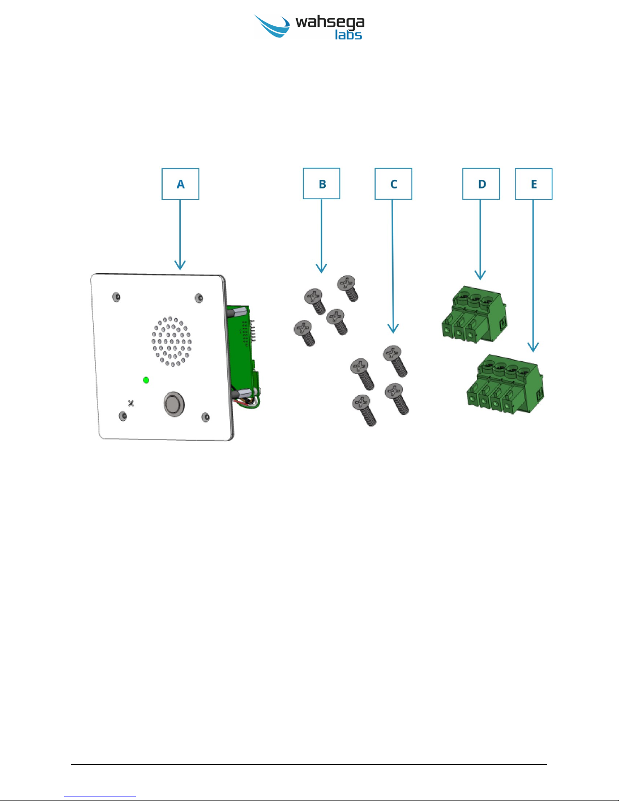
A. (1) VoIP intercom assembly
B. (4) ½” Phillips head faceplate screws for ¼” drywall
C. (4) 1” Phillips head faceplate screws for ½”+ drywall
D. (1) 3-pin male connector for controlling door access
E. (1) 4-pin male connector for request to exit & door
status monitor
www.wahsega.com Page 2

What You Will Need
PoE power
Power-over-Ethernet (PoE) injector
or
PoE capable switch
Remote communication point
SIP server
or
Peer-to-peer device to call
Network cable (Cat 5 or Cat 6)
Screwdriver
Small flat head screwdriver
Phillips head screwdriver
Back box
4-11/16" square back box, minimum 2-½” deep, with
multiple conduit knockouts
(Similar to Orbit 5SLB-MKO or Garvin 72181-S)
Conduit and connectors
See page 13 for details
www.wahsega.com Page 3
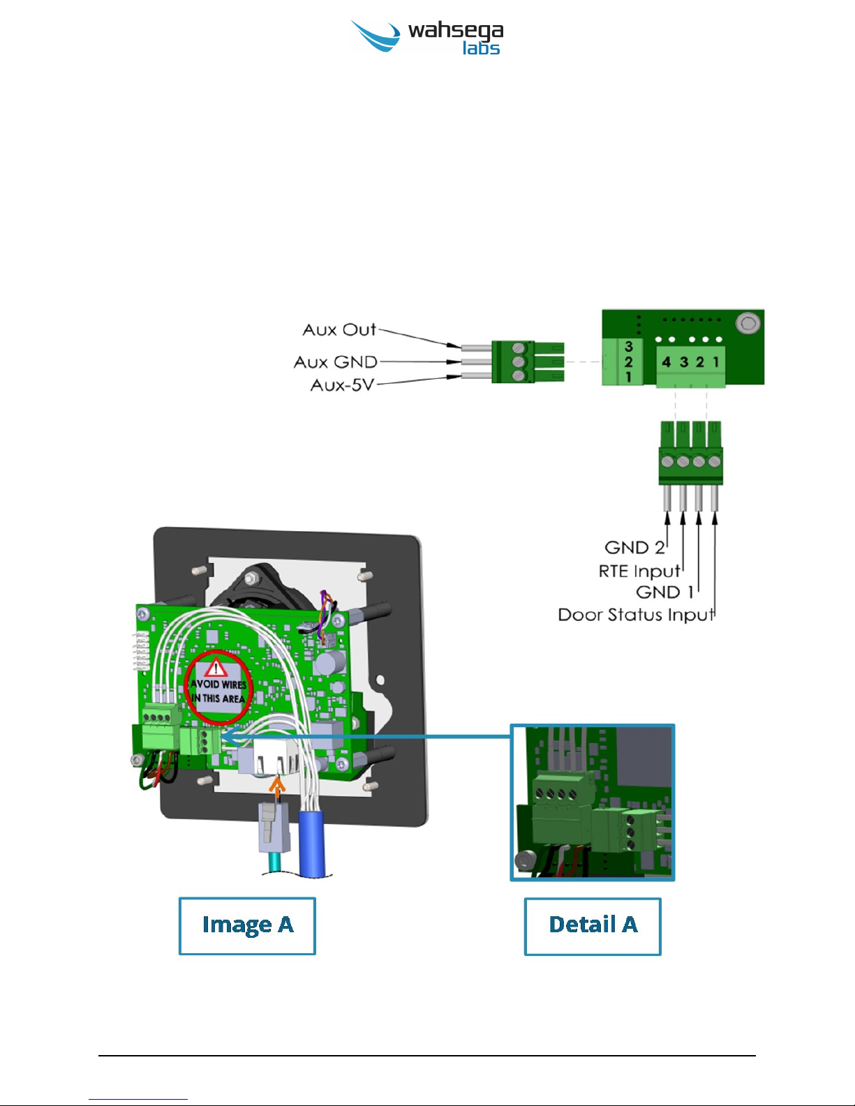
Request to Exit and Door Latch Wiring
The access control intercom provides connections for controlling
magnetic door latches, request to exit (RTE) functionality for buttons
and/or exit motion sensors as well as door closed status monitor.
www.wahsega.com Page 4
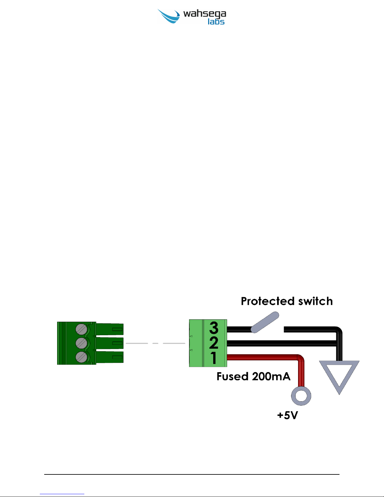
Auxiliary Output (Door Control)
The connector for Auxiliary Output is a 3-pin male connector used to
connect and control door latches, gates and other points of entry.
Pin 1 is a 200mA fused 5V DC signal intended to provide power to
the coil of an external relay.
Pin 2 is ground.
Pin 3 is the auxiliary output, which is voltage and current protected.
The output provides the ground for the external circuit and can be
connected to external devices up to 24V DC and sink up to 1.5A of
current.
www.wahsega.com Page 5
 Loading...