

Wahsega Labs WL-IC-BKMT-SIP-OV Installation Manual
Back Mount
SIP Access Control Intercom
Installer’s Guide
This step-by-step guide will help you install your
Wahsega Labs back mount SIP access control intercom.
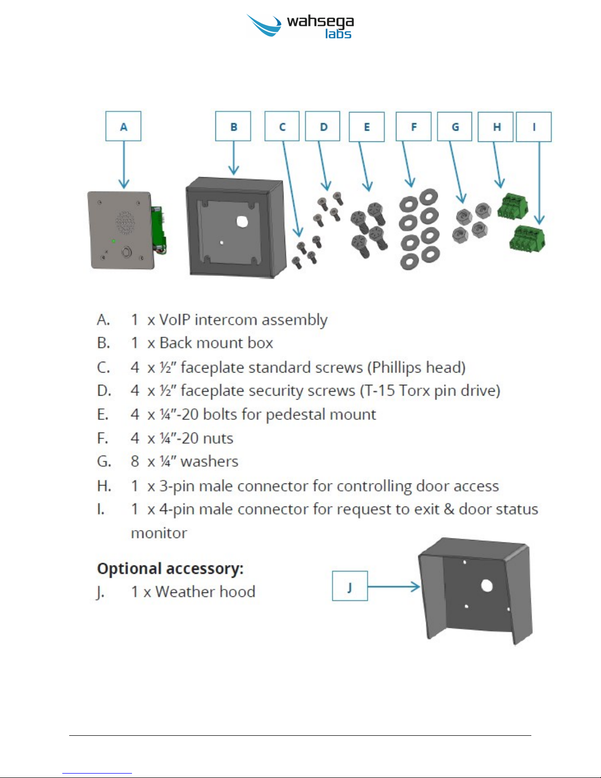
What’s in the Box
www.wahsega.com Page 2

What You Will Need
PoE power
Power-over-Ethernet (PoE) injector
or
PoE capable switch
Remote communication point
SIP server
or
Peer-to-peer device to call
Network cable (Cat 5 or Cat 6)
Wrench or ratchet set
RTV sealant for weatherproofing
Screwdriver
Small flat head screwdriver
Phillips head screwdriver
T-15 Torx pin screwdriver (optional for security screws)
For wall mount installations:
½” conduit
½” set screw style connector
½” conduit nut
½” conduit sealing ring
(4) ¼”-20 concrete or drywall anchors
www.wahsega.com Page 3
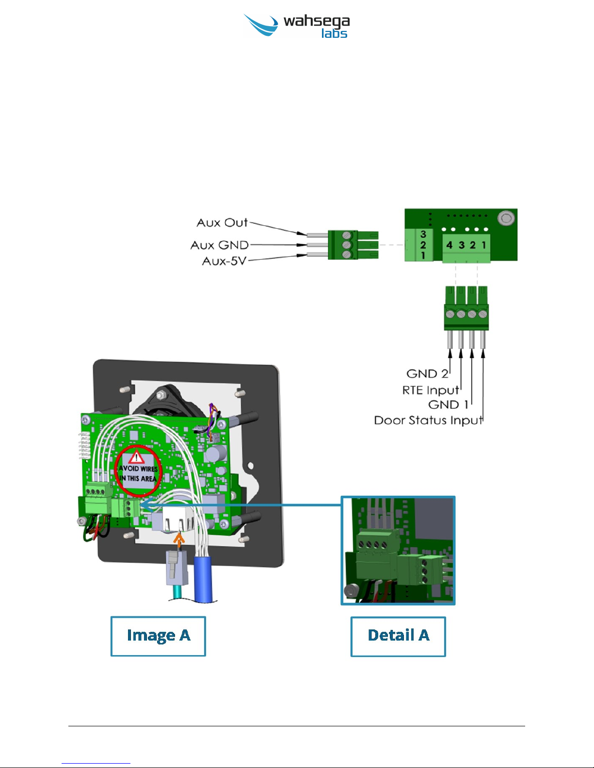
Request to Exit and Door Latch Wiring
The access control intercom provides connections for controlling magnetic
door latches, request to exit (RTE) functionality for buttons and/or exit
motion sensors as well as door closed status monitor.
www.wahsega.com Page 4
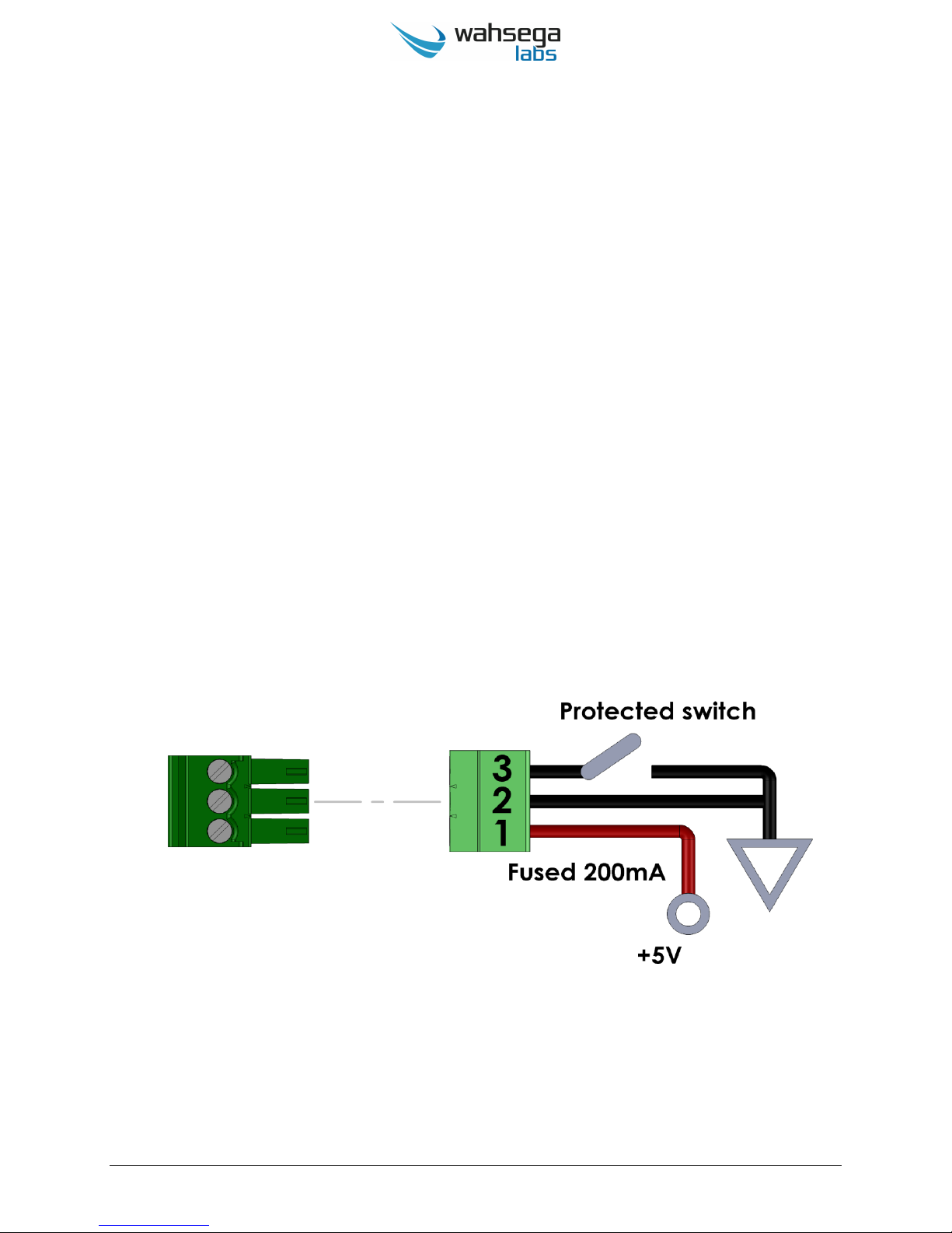
Auxiliary Output (Door Control)
The connector for Auxiliary Output is a 3-pin male connector used to
connect and control door latches, gates and other points of entry.
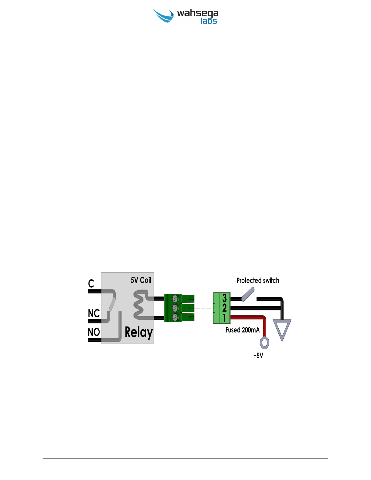
Pin 1 is a 200mA fused 5V DC signal intended to provide power to
the coil of an external relay.
Pin 2 is ground.
Pin 3 is the auxiliary output, which is voltage and current protected.
The output provides the ground for the external circuit and can be
connected to external devices up to 24V DC and sink up to 1.5A of
current.
www.wahsega.com Page 5
Auxiliary Output Configurations
External Relay
Externally Powered Device
External Relay:
An external relay is normally used to switch a voltage or current which
is beyond the direct switching capabilities of the Auxiliary Output.
Examples are higher voltages or AC signals. In this configuration, the
5V DC relay coil high side (if polarized) should be wired to Pin 1 and the
low side wired to Pin 3. The output side of the relay should be rated for
the required load.
www.wahsega.com Page 6
 Loading...