

Page 1
www.twiline.ch
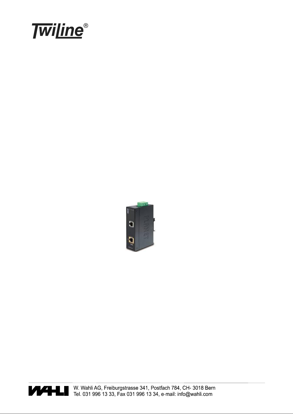
PoE Injector Hutschiene
PoE-H
BESCHREIBUNG
Spannungsversorgung zu den Touch Panels TP-7 und TP-10 mittels Power over Ethernet. Das Gerät wird in
der Verteilung eingebaut. Es benötigt eine Spannungsversorgung 24VDC. Es wird in die LAN-Verbindung
von der Zentrale / Switch auf das Touch Panel zwischengeschaltet.
PoE-H.docx, 10.11.2017
Page 2

Industrial IEEE 802.3at/af
Gigabit PoE+ Injector
IPOE-162
User’s Manual
Page 3

Table of Contents
1. Package Content ....................................................................... 3
2. Product Features ....................................................................... 4
3. ProductSpecication ................................................................. 6
4 Hardware Description ................................................................. 8
4.1 Physical Dimension ............................................................. 8
4.2 Product Outlook .................................................................. 9
4.3 Industrial PoE+ Injector Upper Panel ...................................10
4.4 Wiring the Power Inputs .....................................................10
4.5 Wiring the Fault Alarm Contact ...........................................12
5. Mounting Installation ................................................................13
5.1 DIN-Rail Mounting..............................................................13
5.2 Remove DIN-Rail Mounting .................................................14
5.3 Wall Mount Plate Mounting .................................................15
6. Hardware Installation ................................................................16
Customer Support ..........................................................................19
Page 4

1. Package Content
Thank you for purchasing PLANET Industrial IEEE 802.3at High Power
over Ethernet Injector, IPOE-162. Terms of “802.3at PoE+ Injector”
in following section of this User’s Manual means the IPOE-162.
Upon open the box of the Industrial IEEE 802.3at High Power over
Ethernet Injector and carefully unpack it. The box should contain the
following items:
IPOE-162:
Industrial IEEE 802.3at Gigabit High Power over Ethernet Injector x 1 l
User’s Manual x 1 l
DIN Rail Kit x 1 l
Wall Mount Kit x 1 l
Dusty cap x 2 l
If any of these are missing or damaged, please contact your dealer
immediately, if possible, retain the carton including the original packing
material, and use them against to repack the product in case there is a
need to return it to us for repair.
3
Page 5

2. Product Features
Interface
l 2-Port RJ-45 interfaces
1-Port Data + Power output
1-Port Data input
lOne terminal block for master and slave power input. (Power
Range: 24 ~ 48V DC / 24V AC redundant power.
PoE
l Gigabit High Power over Ethernet Mid-Span PSE
l IEEE 802.3at / 802.3af PoE compliant
l IEEE 802.3at / 802.3af splitter devices compatible
l Support PoE Power up to 30 Watts for PoE port
l Provides DC 56V power over RJ-45 Ethernet cable to device with
Ethernet port
l Auto-detect of PoE IEEE 802.3at / 802.3af equipment and devices
from being damaged by incorrect installation
l Remote power feeding up to 100m
Hardware
l IP30 Slim Type Metal Case
l LED indicators for Power LED and PoE In-Use
4
Page 6
Industrial Case / Installation
Note
l DIN Rail and Wall Mount Design
l Supports EFT protection 6000 VDC for power line
l Supports 6000 VDC Ethernet ESD protection
l -40 to 75 Degree C operation temperature
PD (Powered Device) is a PoE-enabled terminal by PSE
and thus consumes energy, such as IP Phones, network
cameras and Wireless access points, etc.
PSE (Power Sourcing Equipment) is a device (switch,
or hub for instance) that will provide power in a PoE
setup. Maximum allowed continuous output power per
such device in IEEE 802.3af is 15.4W, 30W in IEEE
802.3at.
5
Page 7
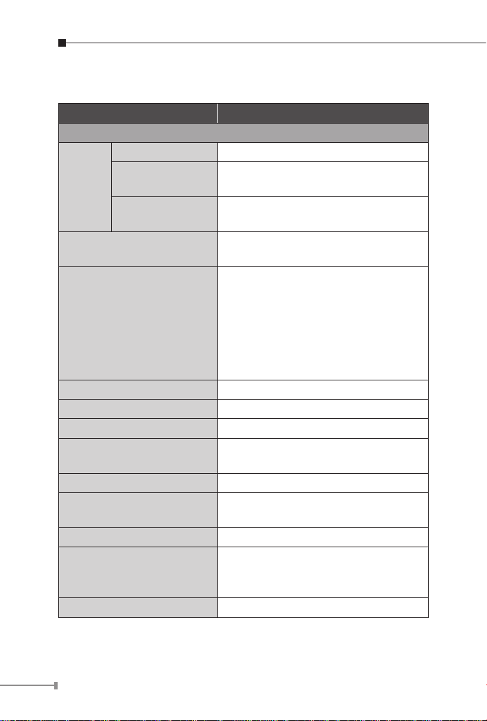
3.ProductSpecication
Product IPOE-162
HardwareSpecication
"Data" Input Port 1 x RJ-45 STP
"PoE (Data+Power)"
Interface
LED Indicator
Network Cable
Data Rate 10/100/1000Mbps
Dimension (W x D x H) 135 x 97 x 32 mm
Weight 473g
Unit Input Voltage
Power Consumption 30 Watts max.
Number of device can be
powered
Installation DIN Rail kit and Wall Mount ear
Alarm
Enclosure IP30 Slim Type Metal Case
Output Port
Input power
terminal block
1 x RJ-45 STP
1
System: Power 1, Power 2, Fault (Green)
PoE Port: PoE In-Use x 1 (Green)
10Base-T:
UTP Cat. 3, 4, 5, up to 100m (328ft)
100Base-TX:
UTP Cat. 3, 4, 5, up to 100m (328ft)
1000Base-T:
UTP Cat. 5, 5e, 6 up to 100m (328ft)
EIA/TIA- 568 100-ohm STP (100m)
24 ~ 48V DC
24V AC
1
Provides one relay output for power fail,
Alarm Relay current carry ability: 3A @
DC 30V
6
Page 8
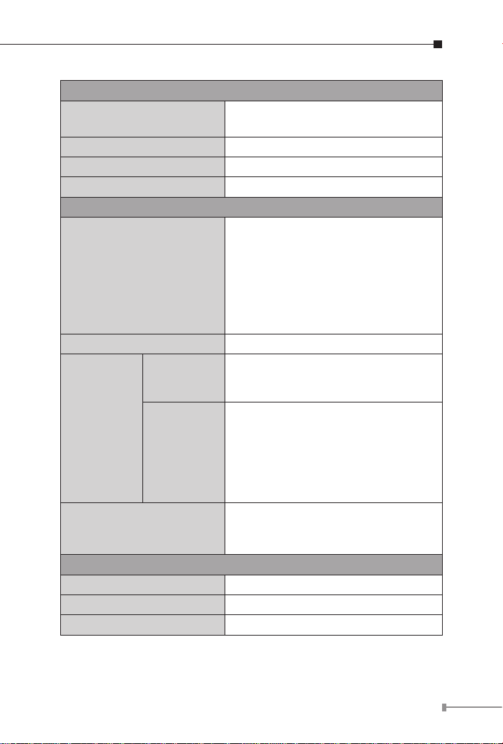
Power over Ethernet
PoE Standard
PoE Power Output DC 56V / 30 Watts
PoE Power supply Type Mid-Span
Power Pin Assignment 4/5(+), 7/8(-)
Standards Conformance
Standards Compliance
FCC FCC Part 15B Class A
EMI
CE
EMS
IEEE 802.3at High Power over Ethernet
/ Mid-Span PSE
IEEE 802.3 10Base-T Ethernet
IEEE 802.3u 100Base-TX Fast Ethernet
IEEE 802.3ab 1000Base-T Gigabit
Ethernet
IEEE 802.3af Power over Ethernet
IEEE 802.3at Power over Ethernet
enhancement standard
EN 55022
EN 61000-3-2
EN 61000-3-3
EN 61000-4-2 (ESD)
EN 61000-4-3 (RS)
EN 61000-4-4 (EFT)
EN 61000-4-5 (Surge)
EN 61000-4-6 (CS)
EN 61000-4-8 (PFMF)
IEC60068-2-32 (Free fall)
Stability Testing
Environment
Operating Temperature -40 ~ 75 Degree C
Storage Temperature -40 ~ 85 Degree C
Humidity 5 ~ 95% (Non-condensing)
IEC60068-2-27 (Shock)
IEC60068-2-6 (Vibration)
7
Page 9
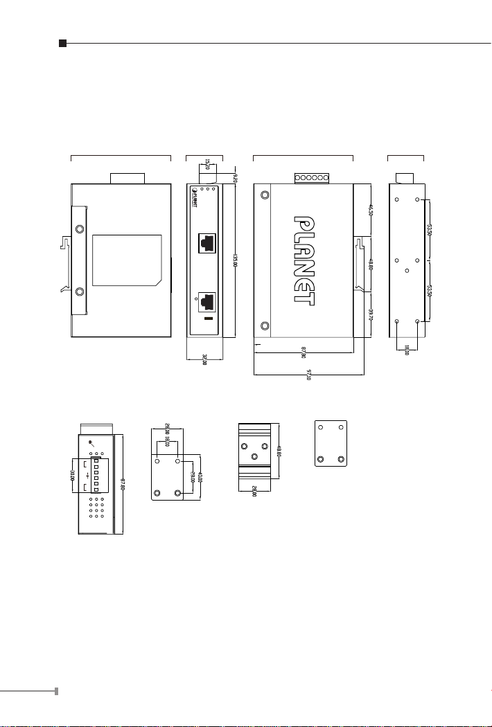
4 Hardware Description
Side View
Bottom View Front View Top View
Mounting Kit Mounting KitDIN-Rail Kit
Rear View
10/100/1000T
10/100/1000T
Ethernet+DC
Ethernet
PoE
In-Use
IPOE-162
P1 P2 FAULT
802.3at
Input
DC 24~48V, AC 24V
V1- V1+ V2- V2+
PWR1
PWR2Fault
4.1 Physical Dimension
8
Figure 4-1
Page 10
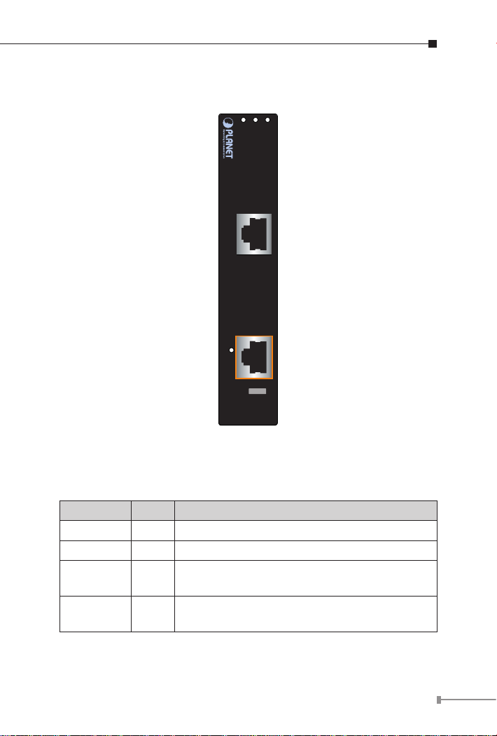
4.2 Product Outlook
10/100/1000T
10/100/1000T
Ethernet+DC
Ethernet
PoE
In-Use
IPOE-162
P1 P2 FAULT
802.3at
LED Indicators
Figure 4-2
LED Color Function
P1 Green Indicate the power 1 has power.
P2 Green Indicate the power 2 has power.
FAULT Green
PoE In-Use Green
Indicate the either power 1 or power 2 has no
power.
Indicate the port is providing 56V DC in-line
power.
9
Page 11
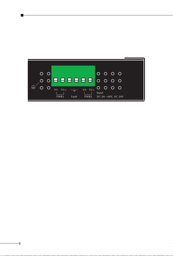
4.3 Industrial PoE+ Injector Upper Panel
1 2 3 4 5 6
The upper panel of the Industrial PoE+ Injector consist one terminal
block connector within two DC / AC power inputs. Figure 1 shows the
upper panel of the Industrial PoE+ Injector.
Figure 1: Industrial PoE+ Injector Upper Panel.
4.4 Wiring the Power Inputs
The 6-contact terminal block connector on the top panel of Industrial
PoE+ Injector is used for two DC / AC redundant powers input. Please
follow the steps below to insert the power wire.
10
Page 12
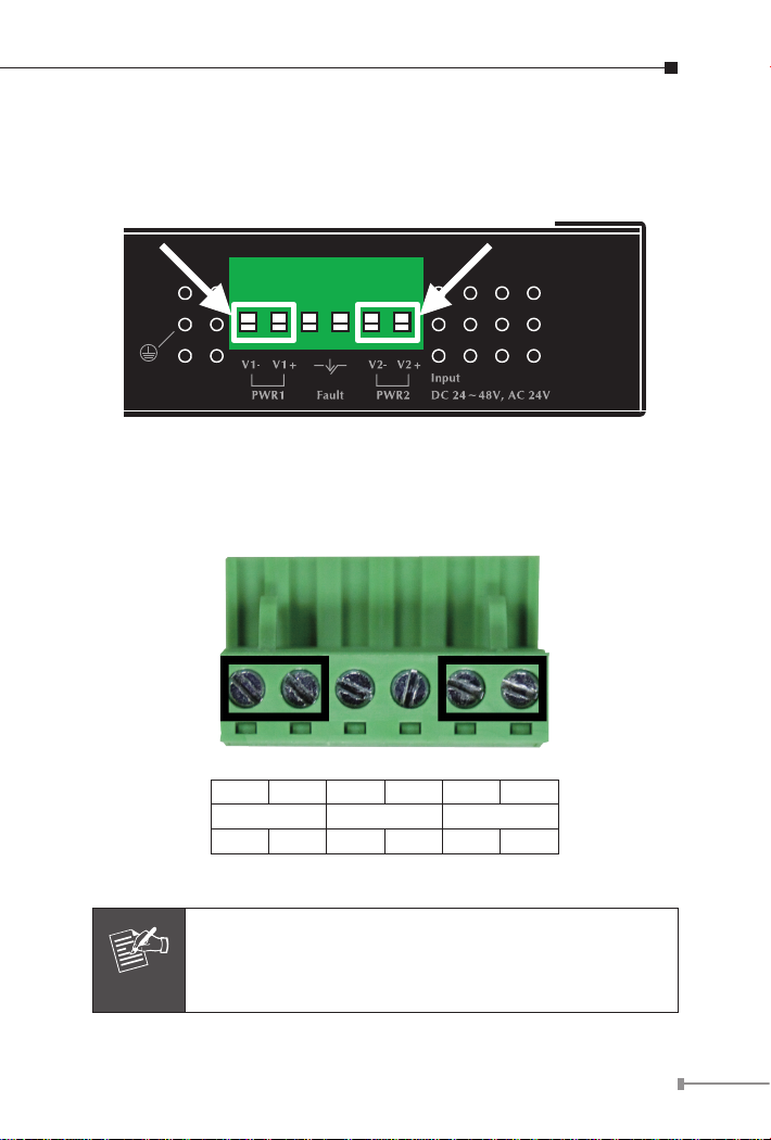
1. Insert Positive / Negative DC power wires or Neutral / Line AC power
1 2 3 4 5 6
Note
wires into the contacts 1 and 2 for POWER 1, or 5 and 6 for POWER
2.
Figure 2: Power input PINs.
2. Tighten the wire-clamp screws for preventing the wires from loosing.
1 2 3 4 5 6
Power 1 Fault Power 2
- + - +
Figure 3: PWR1 & PWR2 Pin of Terminal Block.
The wire gauge for the terminal block should be in the
range between 12 ~ 24 AWG.
11
Page 13
4.5 Wiring the Fault Alarm Contact
Note
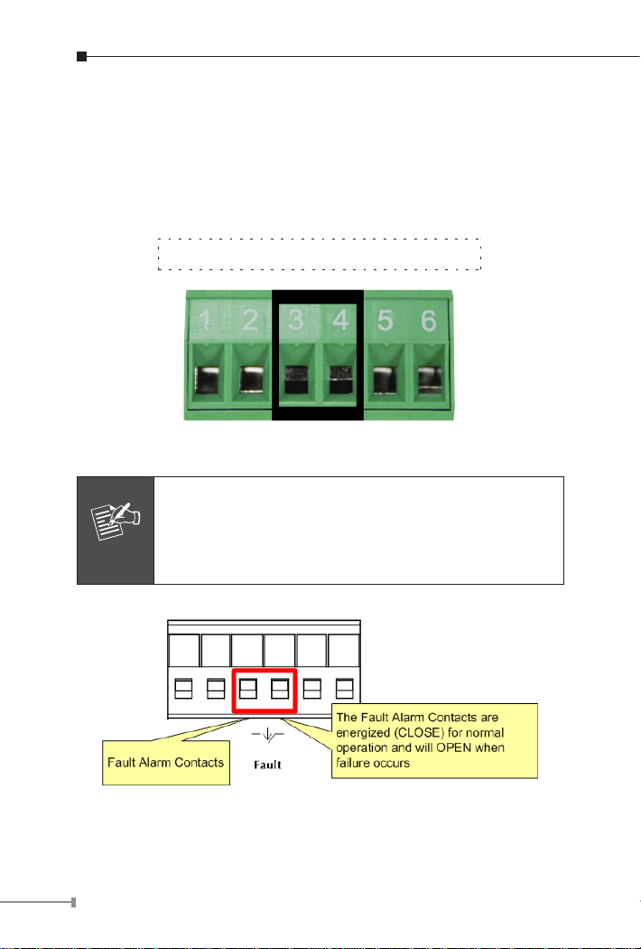
The fault alarm contacts are in the middle of the terminal block
connector as the picture shows below. Inserting the wires, the
Industrial PoE+ Injector will detect the fault status of the power failure
and then forms an open circuit. The following illustration shows an
application example for wiring the fault alarm contacts.
Insert the wires into the fault alarm contacts
Figure 4: Fault Pin of Terminal Block.
1. The wire gauge for the terminal block should be in
the range between 12 ~ 24 AWG.
2. Alarm relay circuit accepts up to 30V, max. 3A
currents.
Figure 5: Fault Alarm Contact.
12
Page 14
5. Mounting Installation
Note
This section describes how to install the Industrial Equipment and make
connections to it. Please read the following topics and perform the
procedures in the order being presented.
In the installation steps below, this Manual use IGS-801
(PLANET 8 Port Industrial Gigabit Switch) as the
example. However, the steps for PLANET Industrial slim
type Switch, Industrial Media / Serial Converter and
Industrial PoE equipment are similar.
5.1 DIN-Rail Mounting
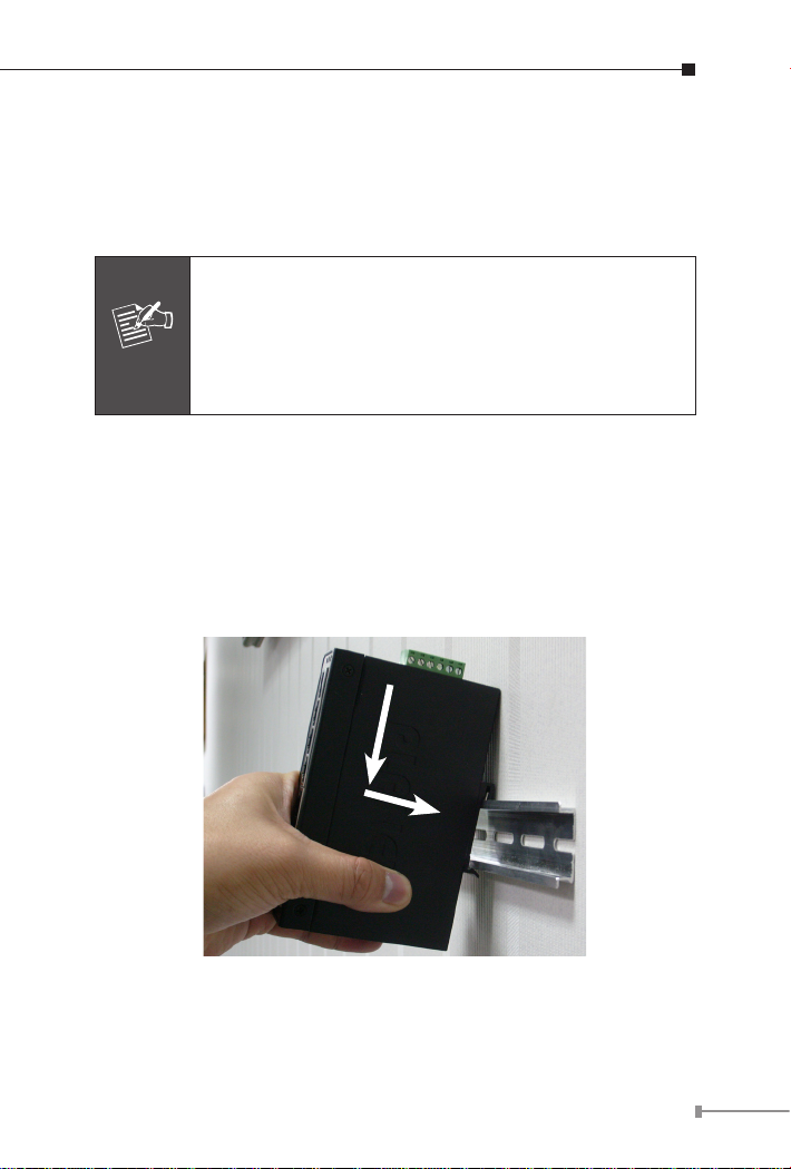
The DIN-Rail is already screwed on the Industrial Equipment. Please
refer to following gures and know how to hang the Industrial
Equipment:
Step 1: Lightly press the button of DIN-Rail into the track.
1
2
Figure 6: Install Industrial Equipment in DIN-Rail mount.
13
Page 15
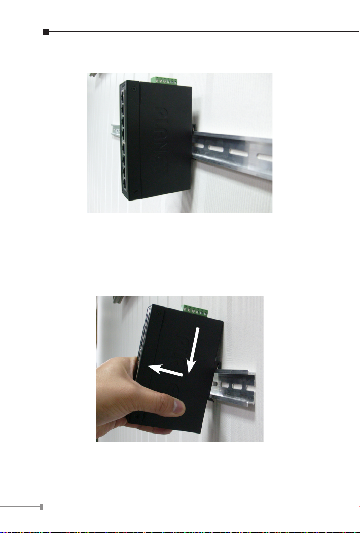
Step 2: Check the DIN-Rail is tightly on the track.
Figure 7: Industrial Equipment installed in DIN-Rail mount.
5.2 Remove DIN-Rail Mounting
Step 1: Please refer to following procedures to remove the Industrial
Equipment from the track.
1
2
Figure 8: Remove Industrial Equipment in DIN-Rail mount.
14
Page 16
Step 2: Lightly press the button of DIN-Rail for remove it from the
track.
5.3 Wall Mount Plate Mounting
To install the Industrial Equipment on the wall, please follows the
instructions described below.
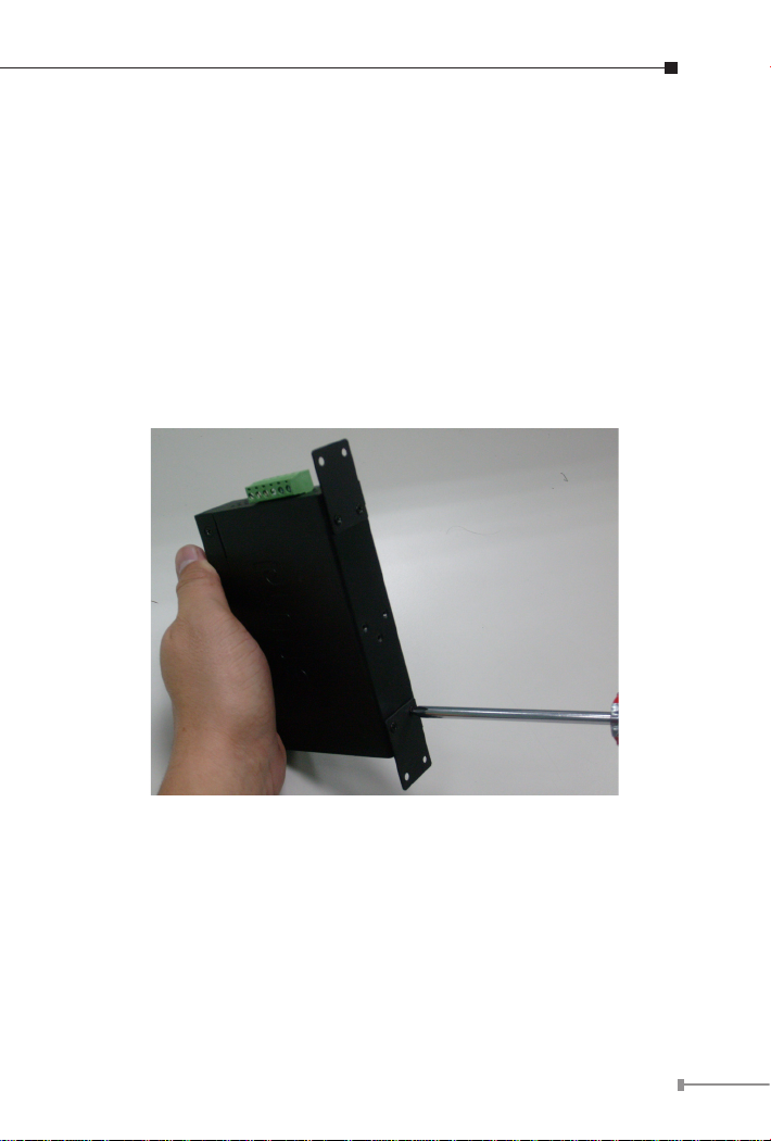
Step 1: Remove the DIN-Rail from the Industrial Equipment; loose
the screws to remove the DIN-Rail.
Step 2: Place the wall mount plate on the rear panel of the Industrial
Equipment.
Figure 9: Attach Brackets to the Industrial Equipment.
Step 3: Use the screws to screw the wall mount plate on the
Industrial Equipment.
Step 4: Use the hook holes at the corners of the wall mount plate to
hang the Industrial Equipment on the wall.
Step 5: To remove the wall mount plate, reverse steps above.
15
Page 17

6. Hardware Installation
Note
This Industrial IEEE 802.3at Gigabit High Power over Ethernet Injector
provides three different running speeds – 10Mbps, 100Mbps and
1000Mbps in the same device and automatically distinguishes the
speed of incoming connection. Please refer to following sections for
detail information about Industrial IEEE 802.3at Gigabit High Power
over Ethernet Injector.
Before Installation
Before your installation, it is recommended to check your network
environment. If there has any IEEE 802.3at devices need to power on,
the IPOE-162 can provide you a way to supply power for this Ethernet
device conveniently and easily.
If there is very difcult to nd a power socket for AC-DC Adapter to
your Non-IEEE 802.3at networked device, the IPOE-162 with POE-162S
/ IPOE-162S can provide you a way to supply DC power for this
Ethernet device conveniently and easily.
The IPOE-162 with IPOE-162S / POE-162S is installed
in pair. However, the use of third-party device is allowed
if the device complied with IEEE 802.3at Power over
Ethernet.
IPOE-162 Injector Installation
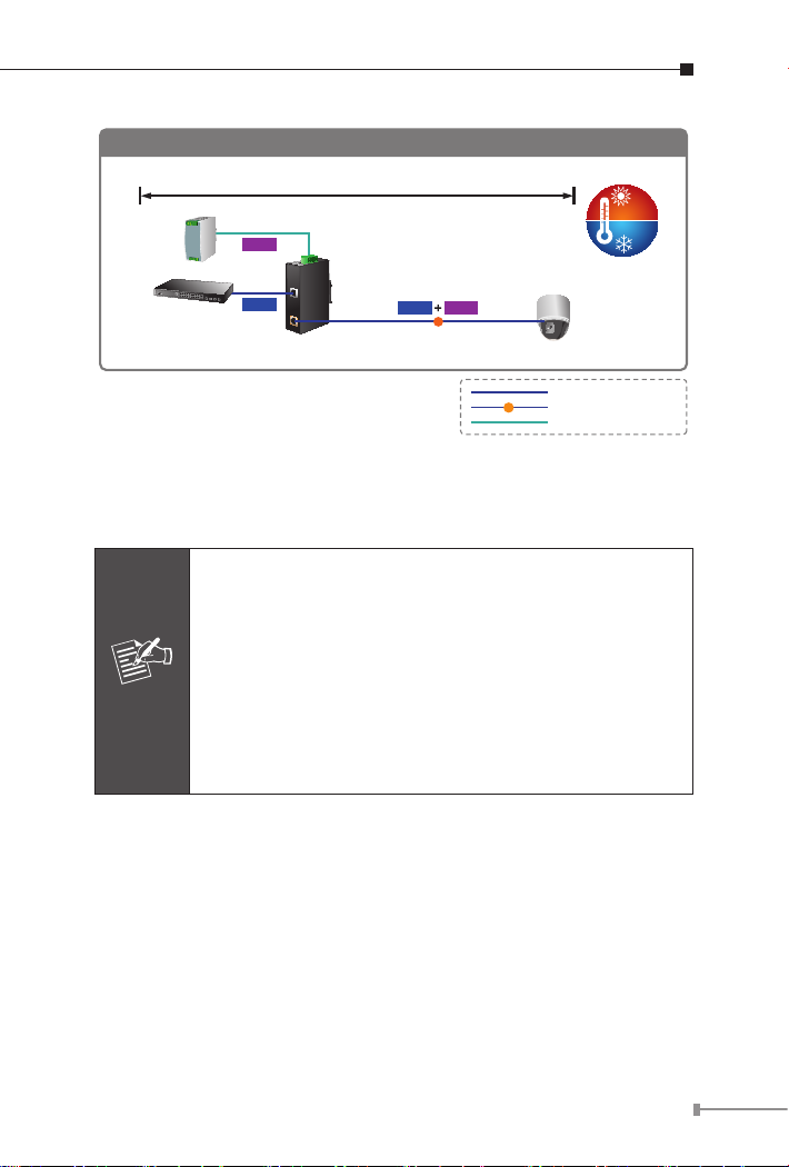
1. Connect the Power (Range from AC 24V or DC 24 ~ 48V) to 6-pin
terminal block of IPOE-162. The power LED will be steady on.
2. Connect a standard network cable from Switch / workstation to
“Ethernet” port of IPOE-162.
3. Connect the long cable that will be used to connect to the remote
device to the port “Ethernet + DC”.
4. Due to the capability of IEEE 802.3at Power over Ethernet, the IPOE162 can directly connect with any IEEE 802.3at / IEEE 802.3af endnodes such as PTZ (Pan, Tilt & Zoom) network cameras, PTZ Speed
Dome, color touch- screen Voice over IP (VoIP) telephones, multichannel wireless LAN access points.
16
Page 18
Power Line
1000Base-T UTP
PoE
1000Base-T UTP with PoE
IPOE-162
Industrial
Switch
Power
Supply
AC 24V/DC 24~48V
IPOE-162 Installation
-40
℃
75
℃
Power
Data
PoE
PTZ Camera
PoE
Power
Data
100 meters
Once IPOE-162 detects the existence of an IEEE 802.3at device, the
Note
POE In-use LED indicator will be steady on to show it is providing
power.
1. Due to the IPOE-162 PoE port supports 56V DC PoE
power output, please check and assure the Powered
Device (PD) acceptable DC power range is from 52
to 56V DC. Otherwise, it will damage the Powered
Device (PD).
2. If the connected device (PD) is not fully complying
with IEEE 802.3at Power over Ethernet or in-line
power device, the IPOE-162 might encounter incompatible issue which fails to power up the devices.
IPOE-162 and IPOE-162S, the IEEE 802.3at Injector Splitter
Installation
1. Connect the Power (Range from AC 24V or DC 24 ~ 48V) to 6-pin
terminal block of IPOE-162. The power LED will be steady on.
2. Connect a standard network cable from “Ethernet+DC” port of
IPOE-162 to “PoE In” port of IPOE-162S. The POE In-use LED of
IPOE-162 / IPOE-162S will light on continuance.
17
Page 19
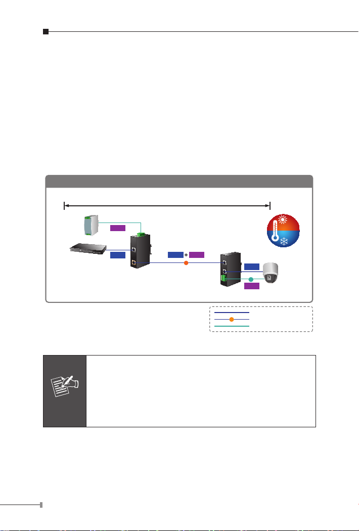
3. Connect a standard network cable from Switch/workstation to
Power Line
1000Base-T UTP
PoE
1000Base-T UTP with PoE
IPOE-162
Industrial
Switch
Power
Supply
AC 24V/DC 24~48V
IPOE-162 + IPOE-162S Installation
-40
℃
75
℃
802.3at
PoE Splitter
Power
Data
Power
DC
PTZ Camera
12V/24V DC Output
PoE
Power
Data
Data
100 meters
Note
“Ethernet” port of IPOE-162.
4. Connect the UTP cable from “Ethernet” port of IPOE-162S to the
RJ-45 port of remote device.
5. Adjust proper DC voltage power output and connect DC plug from
“Power Output” of IPOE-162S to remote device.
6. Power on the remote device and its power LED indicator will remains
on.
18
1. According to IEEE 802.3at Power over Ethernet, the
IPOE-162 will not inject power to the cable if not
connecting to IEEE 802.3at devices.
2. Please ensure the output voltage is correct before
applying power to remote device. Otherwise, it will
damage the Powered Device (PD).
Page 20

Customer Support
Thank you for purchase PLANET products. You can browse our online
FAQresourceatthePLANETWebsitersttocheckifitcouldsolveyou
issue. If you need more support information, please contact PLANET
switch support team.
PLANET online FAQ :
http://www.planet.com.tw/en/support/faq.php?type=2
Switch support team mail address :
[email protected]
Copyright © PLANET Technology Corp. 2012.
Contents subject to revision without prior notice.
PLANET is a registered trademark of PLANET Technology Corp. All other
trademarks belong to their respective owners.
19
Page 21

EC Declaration of Conformity
For the following equipment:
*Type of Product: Industrial IEEE 802.3at High Power over Ethernet Injector (30 Watts)
*Model Number: IPOE-162
* Produced by:
Manufacturer‘s Name : Planet Technology Corp.
Manufacturer‘s Address: 10F., No.96, Minquan Rd., Xindian Dist.,
New Taipei City 231, Taiwan (R.O.C.)
is herewith confirmed to comply with the requirements set out in the Council Directive on the
Approximation of the Laws of the Member States relating to Electromagnetic Compatibility Directive
on (2004/108/EC).
For the evaluation regarding the EMC, the following standards were applied:
EN 55022 (Class A: 2010)
EN 55024 (2010)
IEC 61000-4-2 (2008)
IEC 61000-4-3 (2006 + A1: 2007 + A2: 2010)
IEC 61000-4-4 (2004 + A1: 2010)
IEC 61000-4-5 (2005)
IEC 61000-4-6 (2008)
IEC 61000-4-8 (2009)
Responsible for marking this declaration if the:
Manufacturer Authorized representative established within the EU
Authorized representative established within the EU (if applicable):
Company Name: Planet Technology Corp.
Company Address: 10F., No.96, Minquan Rd., Xindian Dist., New Taipei City 231, Taiwan
(R.O.C.)
Person responsible for making this declaration
Name, Surname Kent Kang
Position / Title : Product Manager
Taiwan
17 Aug., 2012
Place Date Legal Signature
PLANET TECHNOLOGY CORPORATION
e-mail: [email protected] http://www.planet.com.tw
10F., No.96, Minquan Rd., Xindian Dist., New Taipei City, Taiwan, R.O.C. Tel:886-2-2219-9518 Fax:886-2-2219-9528
 Loading...