

Page 1
TM612 and TM612A
Pocket RTD
Thermometer
User Manual
WD1020 Rev F
04/08/15
TM612
- 2 -
Acknowledgements
Thank you for choosing this Wahl Instruments high accuracy measuring instrument. Wahl has been pro viding
high quality, high accuracy measuring instruments for over 50 years.
Because of this, we are able to continue our policy of continuous innovation, which has served our customers
so well for the last 50 years. Wahl Instruments encourages your comments and would willingly accept any
suggestions from you to help us to perfect our know-how and improve our future products.
LIMITED GUARANTEE
LIMITED LIABILITY
Manufacturer warrants the TM612 and TM612A RTD Digital Thermometer to be free from def ects in material or
workmanship under normal us e and service for a period of 12 months from date of purchase. The
Manufacturer agrees to repair or replace any product, which upon examination is revealed to have been
defective due to faulty workmanship or material if re turned to our factory, transportation charges prepaid,
within the above s tated warranty period. This warranty is in lieu of all other warranties, expressed or implied
and of all obligations or liabilities on its part for damages including but not limited to consequential damage s,
following the use or misuse of instruments so ld by the Manufacturer. No ag ent is authorized to assume for
Manufacturer any liability except as set forth above.
Page 2

TM612
-
3 - - 3 -
Unpacking Contents
The T M612 (a ll refere nces t o the T M612 also include the TM612A u nless otherwise indicated) was checked
mechanically and elect rically prior to shipment. The necessary precautions have been tak en to ensure it
reaches the user without being damaged.
Nonetheless, it is wise to make a quick check t o detect any damage tha t may have occurred during transport.
If this is the case, inform the carrier immediately thereof.
The standard accessories are the following:
• This users guide
• 4 AA batteries (1.5V).
• Wrist strap.
• Rubber boot
If s ervice or re-certification of your instrument is needed, please contact us via phone, fax or e-mail, f or a
Return Material Authorization (RMA) number.
If the unit is to be returned, it is preferable to use the original packag ing and return with transportation
charges prepaid.
WARRANTY & CALIBRATION
REGISTRATION at
www.palmerwahl.com/register
Registration is fast and easy. In about a minute you can
have your product automatically registered for Warranty
Protection and our Calibration Rem inder service. Let
Palmer Wahl help you protect your investment, and
maintain product accuracy and compliance with ISO and
other quality standards.
Questions? Call Customer Service
at 1-800-421-2853 or 828-658-3131,
Or email: register@palmerwahl.com
Wahl Instruments, Inc.
234 Old Weaverville Road
Asheville, NC 28804 USA
Phone: 800.421.2853
828.658.3131
Fax: 828.658.0728
e-mail:rma@palmerwahl.com
website:www.palmerwahl.com
T
M612
- 4 -
Contents
A. General ........ ..... .... .... ..... ..... ..... .......... ......... .... ..... ..... ..... .......... ......... ..... .... .... ..... .... 5
A.1 Introduction ....... ..... ..... .......... ......... ..... .... ..... ..... ..... ......... .... ..... .... ..... ..... ..... ......... 5
A.2 Parts ...... ..... ..... ..... .......... ......... .... ..... ..... ..... ..... ......... ..... .... .... ..... ..... ..... .......... .... 5
A.3 Safety..... ..... ......... .... ..... ..... ..... .......... .......... ......... .... .... ..... ..... ..... .......... .......... .... 5
A.3.1 Co mpliance with safety standards ...... ..... ..... .......... ......... .... ..... .... ..... ..... ..... ......... 5
A.3.2 Env ironmental conditions .... ..... ..... ......... ..... .... ..... ..... ..... ......... .... .... ..... ..... ..... .... 6
A.3.3 Wo rn devices .... ..... ..... ..... ......... ..... .... ..... ..... ..... .......... ......... .... .... ..... ..... ..... .... 6
A.3.4 Devic e destruction procedure .... ..... ..... ..... .......... ......... .... ..... ..... ..... .......... .......... . 6
A.3.5 Instr uctions ...... ..... ..... ......... .... ..... ..... ..... ..... ......... .... ..... .... ..... ..... .......... ..... .... 6
A.3.6 Making measur ements ....... ......... .... ..... ..... ..... ..... ......... .... ..... .... ..... ..... ..... ......... 6
A.3.7 Def ects and abnormal stresses .... .... ..... .... ..... ..... ..... .......... ......... .... ..... ..... ..... ...... 6
A.3.8 Def initions...... ..... ..... .......... ......... .... ..... .... ..... ..... ..... ......... ..... .... ..... ..... ..... ...... 7
A.4 Maintenance ...... ..... .... ..... ..... .......... .......... ......... .... ..... .... ..... ..... ..... .......... ......... .... . 7
B. Using the instrument .... ..... ..... ..... ......... ..... .... ..... ..... ..... .......... ......... .... .... ..... ..... ..... .... 8
B.1.1 The keyboard ......... ......... .... ..... ..... ..... .......... .......... ......... .... .... ..... ..... ..... ..... .... 8
B.1.2 The measuring and simulation terminals ........ ..... ..... ..... ..... ......... .... ..... .... ..... ..... .... 9
B.1.3 The USB connector ....... ......... ..... .... ..... ..... ..... .......... ......... .... .... ..... ..... ..... ....... 12
B.1.4 The screen .... .... .... ..... ..... ..... .......... .......... ......... .... ..... ..... ..... .......... .......... .... 12
B.1.5 Get ting started (after power-up) ..... ..... ..... ..... .......... ......... .... ..... ..... ..... ......... ..... 13
B.1.6 Main c haracteristics ..... .... ..... ..... ..... .......... ......... .... .... ..... ..... ..... .......... .......... .. 13
C. Mode Programming ..... .... ..... ..... ..... .......... .......... ......... .... .... ..... ..... ..... .......... .......... .. 14
C.1.1 Resistance or temp erature measurement using resistive sensors ........ ......... ..... .... .... .. 14
D. Related Functions....... ..... ......... ..... .... .... ..... ..... ..... .......... ......... .... ..... ..... ..... ..... ......... 16
D.1 Scaling....... ..... ..... ......... .... .... ..... ..... ..... ..... ......... ..... .... ..... ..... .......... .......... ......... 16
D.2 Differential measurements .... ..... ......... ..... .... ..... ..... ..... .......... ......... .... .... ..... ..... ..... .. 17
D.3 Calibrated sensors ........ .... ..... ..... .......... .......... ......... .... ..... .... ..... ..... .......... ..... ....... 18
D.4 Storage of acquisitions in progress. ..... .... .... ..... ..... ..... ..... ......... .... ..... ..... ..... .......... .... 20
E. Parameter settings ....... ..... .......... ......... ..... .... ..... ..... ..... ......... ..... .... .... ..... ..... ..... ..... .. 27
E.1 Contrast adjustment ..... ..... ..... ......... ..... .... .... ..... ..... ..... .......... ......... .... ..... ..... ..... .... 27
E.2 Date and time setting ..... ..... ..... .......... .......... ......... .... ..... ..... ..... ......... ..... .... ..... .... .. 27
E.3 “Preferences” setting. ..... ..... ..... ......... .... ..... ..... ..... ..... ......... .... ..... .... ..... ..... ..... ....... 28
E.3.1 Filtering setting. ..... ..... ..... ..... ......... .... ..... ..... ..... ..... ......... .... ..... .... ..... ..... ..... .. 28
E.3.2 Display resolution setting. ... ..... ......... ..... .... ..... ..... ..... ......... ..... .... .... ..... ..... ..... .. 28
E.3.3 Lighting duration setting. ........ .... ..... ..... ..... ..... ......... .... .... ..... ..... ..... .......... ....... 28
E.3.4 “Key beeping” setting. ....... .... ..... ..... ..... .......... ......... .... ..... .... ..... ..... .......... ....... 28
E.3.5 Language setting ....... ..... ......... .... ..... .... ..... ..... ..... .......... ......... .... ..... ..... ..... .... 28
E.3.6 Temperature unit setting .... ..... ......... .... ..... ..... ..... ..... ......... ..... .... .... ..... ..... ..... .. 29
E.4 “Maintenance” menu .. .... ..... ..... ..... ......... ..... .... ..... ..... ..... .......... ......... .... .... ..... ..... .. 29
E.4.1 Adjustment from the Maintenance menu ......... .... ..... ..... ..... ..... ......... .... ..... .... ..... .. 29
E.5 “About the instrument” menu ... ..... .......... .......... ......... .... .... ..... ..... ..... .......... .......... .. 31
F. Software Update ......... .... ..... ..... ..... .......... ......... .... ..... .... ..... ..... .......... .......... ......... ... 32
G. Technical specifications....... ..... ..... ......... ..... .... ..... ..... .......... ......... .... ..... .... ..... ..... ..... .. 33
G.1 Measurement Function ....... ......... .... ..... .... ..... ..... ..... .......... ......... .... ..... ..... ..... ......... 33
G.1.1 Resistance .... .... .... ..... ..... ..... ......... ..... .... ..... ..... ..... ......... .... ..... .... ..... ..... ..... .. 33
G.1.2 Temperature by resistive sensors. ... ..... ......... ..... .... ..... ..... ..... ......... ..... .... .... ..... .. 33
Page 3

TM612
- 5 - - 5 -
A. GENERAL
A.1 Introduction
The TM612 is a portable RTD thermometer (compliant with EC standards). It is especially designed for
calibration and maintenance. It is us ed to measure resistance values or temperatures bot h on site and in the
laboratory.
The TM612 features a large number of related functions which extend its range of application:
• Storage of acquisitions and display in the form of tables or trend curves.
• Use of calibrated sensors with their coefficients of correction
A range of improvements facilitates its operation:
• Rapid access to all functions.
• Intuitive user interface.
• 160x160 graphic display
• Connection via 4 mm safety plugs or a miniature flat plug.
• Power supply via 4 AA batteries or rechargeable batteries with rapid internal charger (Option).
The device is housed in an ABS case with a rubber boot.
A.2 Parts
General characteristics:
• Portable device powered by 4 AA batteries (pack of Ni-MH storage batteries, 1.7 Ah optional).
• Hand strap for carrying and use on-site
• Graphic liquid crystal display: 160 x 160 pixels.
• Choice of language used for messages and programming of functions, gauges and parameters via
6-key keyboard + 1 navigator.
• Backlit dis play accessible via a keyboard key, with the possibility o f automatic black-ou t aft er a
specific programmable period of inactivity.
• Appearance: ABS case (with rubber boot).
• Dimensions: 6.18 x 3.35 x 1.77 inches (157 x 85 x 45 mm) (without rubber boot).
• Weight: 10.8 oz. (306 g) without rubber boot.
• IP54 rating in compliance with standard EN 60529
Accessories:
Part No. Name
12436-01 Rechargeable battery pack with charger
12436-04 4 pin RTD connector (
mating plug)
for TM612 and TM630
(and TC622)
12436-05 Carrying Case, hard plastic
12436-06 Rubber boot (replace
ment)
12436-07 Cable, USB 2.0A to Mini USB Type B, 5 pin, 6 ft. length
12436-32 4 pin RTD connector (
mating plug) for TM612A and TM630A
(and TC622A)
A.3 Safety
A.3.1 Compliance with safety standards
The device complies with the applicable standards in force on the subject of electrical safety (EN 61010) as
well as on the electromagnetic compatibility of the electrical measuring instruments (EMC: EN61326).
These instructions for use contain information and warnings which must be observed by the user to protect
the latter against the dangers of electricity, to ensure the safe operation of the device and to protect it against
any mishandling which could damage or compromise the safety of use of the device.
TM612
- 6 -
A.3.2 Environmental conditions
In accordance with publication CEI 359: operating category I.
Range of application of standards from 0 to 2,200 m.
Reference temperature range: 23°C ± 5°C, relative humidity: 45 % to 75 %.
Nominal operating range: -10°C to +50°C, relative humidity: 20 % to 80 % non-condensing.
Operating range limit: -15°C to +55°C, relative humidity: 10 % to 80 % (70 % at 55°C).
Storage and transport temperature range limit: - 30°C to + 60°C (without the batteries).
A.3.3 Worn devices
Worn electrical d evices can pollute the env ironment. We recommend you refrain from disposing of this device
in an ordinary waste bin, but rather that you use the recycling circuits available locally.
A.3.4 Device destruction procedure
Opening the d evice: unscrew the sc rew on the b attery compartment, followed by the 5 screws securing the 2
shells.
Separate the 2 shells. Separate the PCB from the upper shell.
With regard to the batteries, you will find them in the battery compartment (see commissioning chapter).
In t he case of the pack of batteries, there are 2 co ntaminants: NI-MH (Nickel-Metal Hyd ride) batteries and a
PCB. Separate these 2 items.
A.3.5 Instructions
The device was designed to operate safely if the instructions provided in the accompanying documents are
followed. Any other use may jeopardize the safety of the operator. Any use other than those specified in the
instructions is therefore dangerous and forbidden.
A.3.6 Making measurements
The measuring leads and wires must be in good condition and must be replaced if their insulation appears
faulty (insulating material cut, burned, etc).
Never exceed the protection value limits indicated in the specifications.
Before changing function, disconnect the measuring wires from the external circuit. When voltage
measurements are being made, even weak ones, keep in mind that the circuits may contain a dangerous
voltage for the operator when referenced to ground.
Do not make any measurements when the device is linked up to another device using the USB link or when
the batteries are being charged.
A.3.7 Defects and abnormal stresses
If you believe the device’s protection may have been compromis ed, switch off the device and prevent it fro m
being switched back on unexpectedly.
The protection may be impaired in the following cases, for example:
The device is visibly worn.
The device is no longer able to make precise measurements.
The device was stored in unfavorable conditions.
The device has undergone severe stresses during transport.
Page 4
TM612
-
7 - - 7 -
A.3.8 Definitions
A.3.8.1 Definition of the category and degree of pollution
CAT II 60V:
This notion of categories determines t he maximum voltage which can be applied to the measuring inpu ts (it is
also referred to as the over voltage category). For the TM612, the ceiling over voltage is (DC or AC)
POL 2°:
The notion of pollution determines the clearanc e between circuits. Degree 2 authorizes temporary con ductivity
caused by condensation.
A.3.8.2 Table of symbols used
Symbol Name Attention: see the accompanying documents
Earth
Compliant with the European Union directives
60V CAT II Pol 2
Category II, Pollution 2.
Maximum common mode voltage compared with the ground=60V
A.4 Maintenance
The device must always be repositioned in accordance with the instructions provided herein. Any incomplete or
incorrect assembly could compromise the safety of the operator.
The authority responsible must regularly ensure that all safety-related items are not worn and ensure all the
preventive maintenance operations required are performed.
Before opening the device for any maintenance operations, you must make sure that all the wires are
disconnected from the appliance.
All adjustments, maintenance and repair work on the open device must be avoided as much as possible and,
when these are indispensable, they must be performed by qualified staff, who are well aware of the risks
involved.
T
M612
- 8 -
B. USING THE INSTRUMENT
In order to use the device in a safe manner, all operators must read the paragraph on safety carefully, along
with the paragraph below.
B.1 Power-up
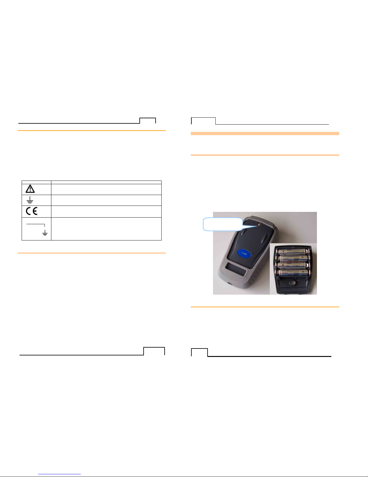
The device is delivered with 4 AA batteries of 1.5V each. To install the batteries into the compartment,
unscrew the screw on the back of the unit. Once the batteries are in place, screw the cover back on.
Observe the polarity: an incorrect battery positioning could damage the device. The correct polarity is
indicated inside the compartment. The figure below illustrates how to open the battery compartment as well as
the correct positioning of each battery.
To turn the unit ON, press the ON/OFF key until the first “Checking EEPROM” screen comes up. (This may
require pressing and holding the key for up to 5 seconds.)
To turn the unit OFF, press the ON/OFF key until the “Instrument in power off mode” screen comes up. Please
note: instruments, whose serial number ends in “B”, will not retain the time and date when powered off. If
time and date need to be retained, the unit can be put in standby mode.
To enter standby mode, press both the HOLD and ON/OFF buttons until the screen displays “Instrument in
standby mode”.
To return to normal operating mode from standby mode, press the ON/OFF key until the original screen comes
up. Please allow a minimum of 10 seconds between going into standby mode and returning from it.
B
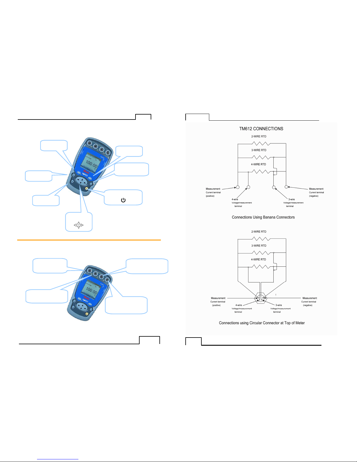
.1.1 The keyboard
The keyboard features:
• 2 function keys (F1 and F2) for the selection of the various menus displayed on the screen.
• The navigator, consisting of 4 arrows (up (↑↑↑↑), down (↓↓↓↓), right (→→→→), left (←←←←).
• A clear key (CLEAR).
• A device on/off and backlighting on/off key (ON/OFF).
Press briefly to start the device. During operation, press briefly to turn the backlight on or off.
Press it longer for 2 seconds to turn off the device.
• A validation key (VAL).
• A HOLD key allows you to suspend a process temporarily (when pressed briefly). If you press it
longer, this key makes it possible to switch from measuring mode to emission mode and viceversa.
Battery
compartment screw
Page 5
TM612
-
9 - - 9 -
B
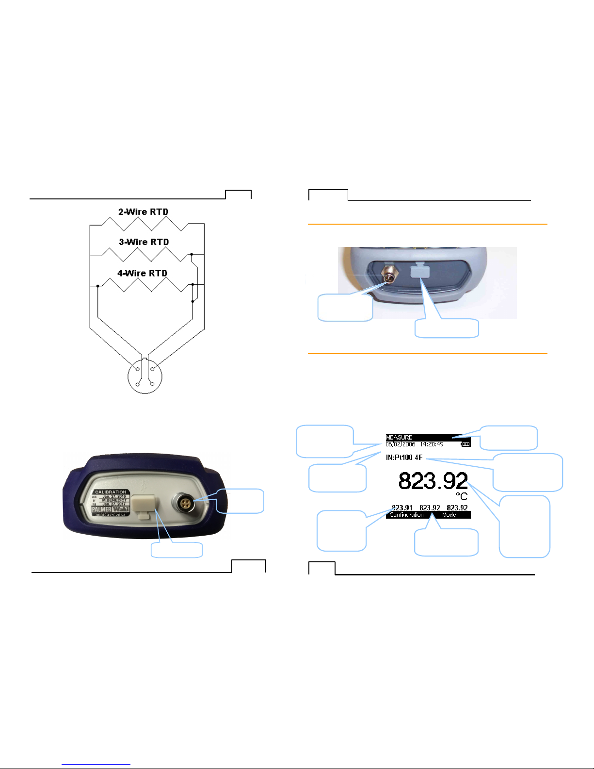
.1.2 The measuring and simulation terminals
The TM612 is fitted with 4 safety banana jacks (4 mm in diameter) and a 4-pin circular connector. These
connector assemblies are used for measurements.
HOLD
key
F1
function
key
CLEAR
key
Navigation
key
ON/OFF key
Confirmation key
(VAL)
F2 function
key
Measurement:
Current terminal
(positive)
4-wire
voltage/measurement
terminal
Measurement:
Current terminal
(negative)
3-wire
voltage/measurement
terminal
T
M612
- 10 -
Page 6
TM612
- 11 - -
TM612A Connector
TM612
- 12 -
B.1.3 The USB connector
The T M612 is fitted with a USB connector ( mini B) intended f or uploading new s oftware versions and device
adjustment.
B.1.4 The screen
The TM612 is fitted with a graphic LCD display with back-lighting. The display resolution is 160 x 160 pixels.
In normal operating conditions, the display is divided up into seven horizontal fields:
• The 1st field indicates the operating mode.
• The 2nd field indicates the date, time and battery charge.
• The 3rd field is reserved for icons indicating the operating mode (related functions: Scaling,
filtering, etc).
• The 4th field indicates the operating mode, the gauge and certain related
functions.
• The 5th field indicates the value of the measurement. T hese values are expressed in ohms, °C, °F
or %.
• The 6th field indicates (in measurement mode) the minimum, average and maximum values of the
measurement.
• Lastly, the 7th field indicates the function of keys F1 and F2.
1st field
indicating the
operating mode
2nd
field
indicating the
Date, time and
battery charge.
3rd
field
indicating the
configuration by
pi
ctograms
4th field indicating the
measurement, the
gauge and the main
related functions.
5th field
indicating the
value of the
measurement
of the
transmission
setpoint (in
mV, °C, °F or
%)
6th field
indicating the
min, avg and
max.
measurement
values.
7th
field indicating
the functions of the
F1 and F2 keys.
USB port
(mini B connector)
US B port
(mini B connector)
TM612A
Connector
TM612
Connector
TM612
Connector
Page 7

TM612
-
13 - - 13 -
The table below provides a definition of each pictogram displayed on the screen:
Symbol Description
Scaling On hold Filtering %FS function (Full Scale)
Error
Condition
- indicates open input or extreme over-range of instrument
(negative symbol with 6 dashes)
+ : indicates measurement is over- range of instrument
(positive symbol, colon and 5 dashes)
- : indicates measurement is under-range of instrument
(negative symbol, colon and 5 dashes)
Incremental mode using the arrows
Battery life indication
Acquisition in progress (the value on the right of the pictogram indicates the
number of values recorded)
The table below provides a definition of each pictogram of the function keys
Symbol Description
Tab key
Open a drop-down list
Close a drop
-
down list Delete the selected item
Clear the selection
Add the item being edited
B
.1.5 Getting started (after power-up)
On power-up (inserting the batteries or p ack of batter ies), the device is automatically turned on (lo ading the
software in the memory).
B.1.6 Main characteristics
B.1.6.1 Resistance/temperature measurement
The following gauges are available:
Gauge 400 Ohm (for PT100) 3600 Ohm (for
PT1000)
Resolution (display)
10 m
Ω or 0.01 °C or
0.01°F 100 m
Ω or 0.01 °C or
0.01°F
Scope of range:
0 Ω to 400 Ω
-220°C to 850°c
-
220.00 °C to 850.00 °C
0
Ω to 3600 Ω
-220°C to 760°C
-
220.00 °C to 760.00°C
Scaling yes yes
B.1.6.2 Electrical characteristics not to be exceeded.
Function Gauges Max Vin I measurement
Ohm measurement 400Ω/3600Ω 60 V
TM612
- 14 -
C. MODE PROGRAMMING
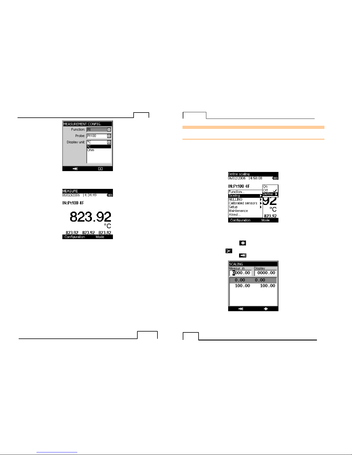
C.1.1 Resistance or temperature measurement using resistive sensors
• The function type selection (Resistive sensor type) is made using the F1 key (Configuration
menu).
• Using the navigation keys (↑↑↑↑ and ↓↓↓↓), position the cursor in the Function field.
• Confirm the latter using the VAL key.
In the MEASUREMENT CONFIGURATION menu, position the cursor in the Probe field using the F1
key.
• Enter the Probe menu using the F2 key.
• Choose the type of sensor (PT50, PT100, PT200, etc), using the navigation keys (↑↑↑↑ and ↓↓↓↓).
• Press VAL to confirm.
• Using the F1 key, define the Display Unit by positioning the cursor on it.
• Enter the menu by pressing F2.
• Using the navigation keys (↑↑↑↑ and ↓↓↓↓), select the unit.
• Press VAL to confirm.
Page 8
TM612
- 15 - - 15 -
Attention, the choice of °C or °F is made in the Setup\Preferences\Unit of temp. menu
• Press VAL (again) to confirm the desired function and go back to the measurement screen.
The Measure mode makes it possible to display the Minimum (bottom left), Average (bottom center) and
Maximum values (bottom right) from the last Min/Max reset command.
• Access this command by pressing the F2 key.
• Using the navigation keys (↑↑↑↑ and ↓↓↓↓), position the cursor in the Min/Max reset field.
• Confirm the latter using the VAL key.
TM612
- 16 -
D. RELATED FUNCTIONS
D.1 Scaling
The scale correction function performs conversion operations between the electrical values measured and the
physical values converted.
This linearization op eration makes it possible to p artially correct the errors induced by non-linear
sensor/converter systems.
The Scaling func tion allows definition o f up to 11 correction values, i.e. 10 segments, in order to a pproach as
much as pos sible the no n-linear response curve, and to make th e scale corr ections according to each defined
segment.
The pictogram is displayed on the screen in the active window when the scaling function is enabled.
The Define/list of points menu makes it possible to program up to 10 lines of 2 values: X and Y= f(X).
In measurement mode: X = Value measured and Y = Value Displayed.
The lines entered are sorted according to the X in increasing order, to scale an X-value, the device seeks the 2
lines n and m=n+1 which frame it, and extrapolates linearly: Y = Yn + (X-Xn) x (Ym-Yn)/(Xm-Xn)
Use the function keys to edit the points:
To add a line: enter X and Y, then press the function key.
To select a line in a list, use the Up and Down navigation keys.
To delete a selected line, use the key.
To move from one field to the next, use the key.
The Define/parameters menu makes it possible to define the format (Number of digits displayed) and unit.
Page 9

TM612
-
17 - - 17 -
O
nce the parameters have been set, the scaling is automatically enabled. To disable it, enter the
Configuration/Scaling ON menu, select OFF and confirm by pressing the VAL key.
D.2 D ifferential measurements
The relative measurement function available on the device makes it pos sible to cance l a constant or spurious
value via programming. Selecting Configuration/NULLING/ON will null out the value defined in the Tare
value box. Selec ting Tare w ill null the cur rent value displayed and will update the NULLING/Define... Tare
value box with this new value. Selecting Configuration/NULLING/OFF will return the unit to its original
display value.
When the relative measurement function is enabled, the symbol is displayed on the measurement
screen.
Scaling
pictogram
Pictogram of the
TARE mode
T
M612
- 18 -
The NULLI NG/Define menu makes it p ossible to program the value of the Tare (positive or negative). This
value is obtained from the measurements:
Value Displayed = Value measured – Value of the Tare
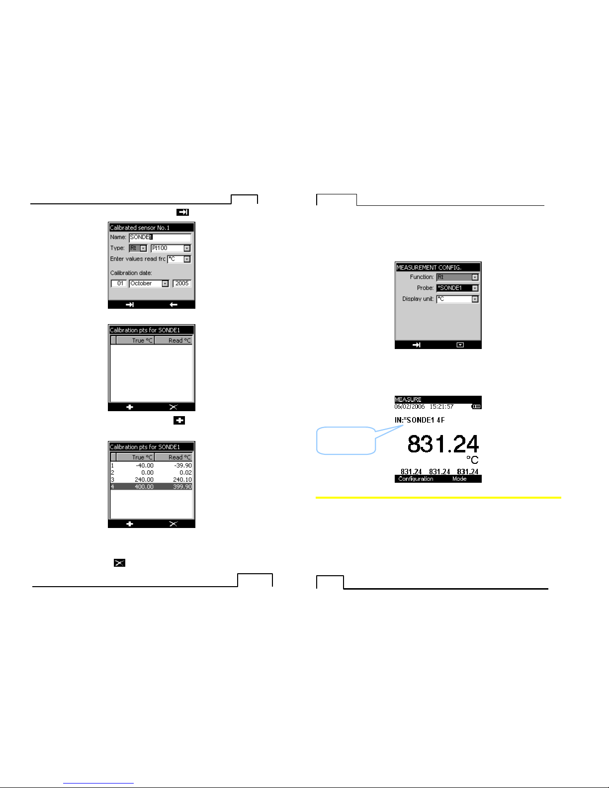
D.3 Calibrated sensors
The calibrated sensors function of the device makes it possible to use sensors, the calibration (co rrection)
coefficients of which are taken into consideration by the device during measurement.
• Using t he F1 key, enter the Configuration menu.
• Select the Calibrated sensors function, followed by one of the 5 available sensors.
• Confirm by pressing VAL.
Page 10
TM612
-
19 - - 19 -
• Enter the sensor information fields. Use the F1 function key ( ) to move from one field to the next.
• Confirm your choice using the VAL key.
• To add a value in the tab le of calibration points, use the keys, enter the c alibration points (real
value and value read) then confirm using the VAL key.
• Repeat this operation for all the calibration points (maximum of 4).
To delete a line, select it then use the key.
T
M612
- 20 -
To edit a line, select it then use the navigation key () to make editing possible.
• Confirm using the VAL key to return to the measurement screen.
To ensure the measur ements are made using t he calibration coefficients defined earlier, g o to the
Configuration/Function menu.
• In the Probe field, select sensor1 (SONDE1-SENSOR1 below).
Note: the Calibrated sensors are at the top of the list and their name is preceded by an *.
• Confirm the latter using the VAL key.
The chosen calibrated sensor is displayed in the measurement screen.
D
.4 Storage of acquisitions in progress.
The TM612 is designed to store 10,000 values in one or more acquisition bursts.
• Using t he F2 key, enter the Mode menu.
• Select the Memory function.
• Confirm us ing the VAL key.
Name of
calibrated sensor
used
Page 11
TM612
-
21 - - 21 -
T
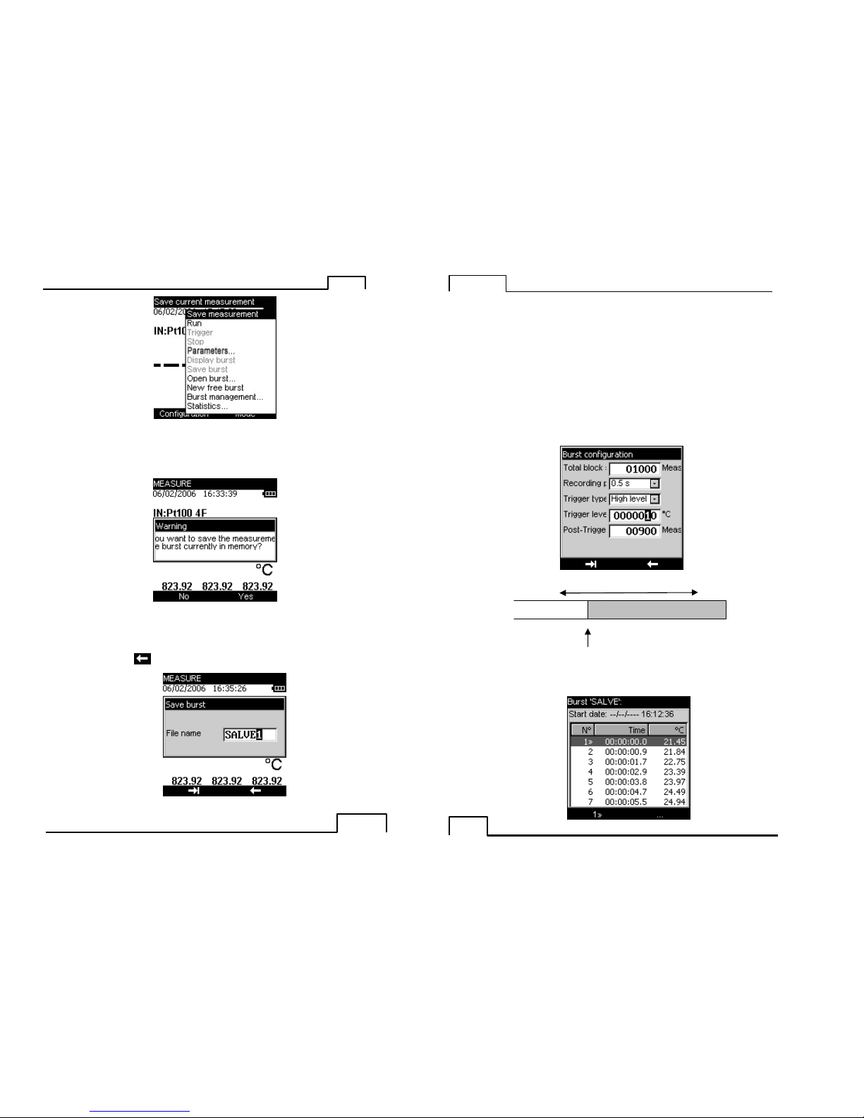
he drop-down list displays the following functions:
SAVE MEASUREMENT:
Enable the triggering of an acquisition on a case-by-case basis.
If an acquisition has already been opened, then the following screen is displayed:
Press the F2 key (YES) to confirm.
• You are then requested to enter the name of a file. Using the navigation keys (↑↑↑↑ and ↓↓↓↓), scroll
down the letters.
• Using the navigation keys ( and ), move the cursor by one position.
• Using the F2 key( ), you can delete the characters entered
• Once you have entered the file name, confirm by pressing the VAL key.
T
M612
- 22 -
RUN:
Launches the storage of data following the parameters set in the “parameters” function. The p ictogram is
displayed on the measurement screen
STOP:
Stops the storage in progress.
PARAMETERS:
Allows you to define:
• The size of the acquisition (max 10,000 values),
• The sampling period from 0.5 S to 30 Min,
• The type of trigger (None, low level, high level).
If you have selected a low level or high level trigger, you must define the trigger level and the number of data
to record after this trigger (Post-trigger).
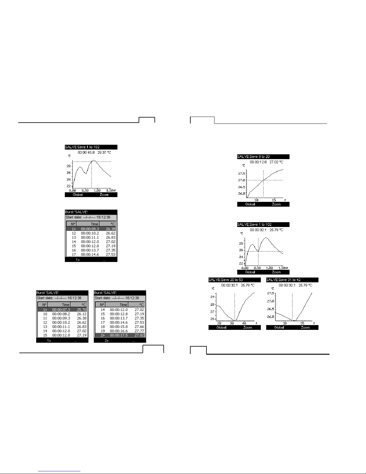
Display burst:
You can display the burst in the form of a table of values or a trend curve.
Post trigger = 900 measurements
Size of block (1,000 meas
urements)
Trigger on programmed
value= 10 °C
Page 12
TM612
- 23 - - 23 -
At this level, it is possible to
- display the trend curve entirely: press the F1 key (GRAPH).
- or place markers so as to display in the form of a gra ph all the values included between these 2 markers. To
do so, press the F2 key.
• Using the navigation keys (↑↑↑↑ and ↓↓↓↓), move the cursor to the value to be marked “value 1” and
press the F1 key (1>>).
• For the second marker, press the F2 key (…) and using the navigation keys (↑↑↑↑ and ↓↓↓↓), move the
cursor to the value to be marked “value 2” and press the F1 key (2>>).
TM612
- 24 -
In this particular example, the graph will display values included between positions 9 and 20.
• Press the F2 key twice, to reach the GRAPH function, then press F1 to confirm.
At th is level, you can display the whole curve or a zoom around the curso r. The cursor is moved us ing the
navigation keys ( and )
• Press CLEAR to return to the table of values.
Page 13

TM612
- 25 - - 25 -
At this level, you can find out some statistics on the measurements made (Minimum, Maximum, Average and
Standard Deviation).
• Press the F2 key three times (…) followed by the F1 key (STAT).
• Press F2 (measurements) to return to the table of values.
• Press CLEAR to quit the storage function.
Save burst:
This function makes it possible to record the burst in the memory.
• You are then requested to enter the name of a file. Using the navigation keys (↑↑↑↑ and ↓↓↓↓), scroll
down the letters.
• Using the navigation keys ( and ), move the cursor by one position.
• Using the F2 key( ), you can delete the characters already entered
• Using the F2 key( ), you can delete the characters entered
• Once you have entered the file name, confirm by pressing the VAL key.
Open a burst:
Allows yo u to choose a specific b urst from the list and open it to dis play the values. At this level, you c an
obtain information on the acquisition burst, such as the number of measurements, the date o f acquisition, the
sensor used, etc.
New free burst:
TM612
- 26 -
Allows you to start a new acquisition burst. If a burst is under way, you will be requested to save it.
Burst management:
Allows you to display all the bursts recorded. At this level, you can delete one or all bursts.
Statistics:
Allows you to find out the number of bursts recorded, the number of bytes free as well as the number of
measurements that can be recorded.
Page 14

TM612
-
27 - - 27 -
E. PARAMETER SETTINGS
E.1 Cont rast adjustment
In the CONFIGURATION/SETUP menu, you can adjust the display contrast.
• Access this menu using the F1 key.
• Select the Setup field using the navigation keys (↑↑↑↑ and ↓↓↓↓), then confirm.
• Select the Contrast field using the navigation keys (↑↑↑↑ and ↓↓↓↓), then confirm.
• Using the navigation keys ( and ), modify the contrast as required.
E.2 Date and time setting
In the CONFIGURATION/SETUP menu, you can set the time and date.
• Access this menu using the F1 key.
• Select the Setup field using the navigation keys (↑↑↑↑ and ↓↓↓↓), then confirm.
• Select the Date/hours field using the navigation keys (↑↑↑↑ and ↓↓↓↓), then confirm.
• Use the navigation keys (↑↑↑↑ and ↓↓↓↓) to modify the various parameters.
• Use the navigation keys ( and ) to go to the next field.
• Press VAL to confirm.
T
M612
- 28 -
E.3 “Pre ferences” setting.
E.3.1 Filtering setting.
In the event of noisy measurements, you can filter the latter to make the value displayed on the screen more
stable.
• Access this menu using the F1 key (configuration menu).
• Select the Setup field using the navigation keys (↑↑↑↑ and ↓↓↓↓), then confirm.
• Select the Preferences field using the navigation keys (↑↑↑↑ and ↓↓↓↓), then confirm.
• Select the Filtering field by pressing the F1 key.
• Four filtering values are available (OFF, 0.5s, 1s and 2s). Select these values using the navigation
keys (↑↑↑↑ and ↓↓↓↓).
• Confirm by pressing the VAL key.
E.3.2 Display resolution setting.
In the CONFIGURATION/SETUP/PREFERENCES menu, you can select the desired display resolution:
• Access this menu using the F1 key.
• Select the Setup field using the navigation keys (↑↑↑↑ and ↓↓↓↓), then confirm.
• Select the Preferences field using the navigation keys (↑↑↑↑ and ↓↓↓↓), then confirm.
• Select the Display resolution field by pressing the F1 key.
Three types of resolution are available: high (.01), medium (.1) and low (1).
• Select this resolution using the navigation keys (↑↑↑↑ and ↓↓↓↓).
• Confirm by pressing the VAL key.
E.3.3 Backlight duration setting.
In the same menu (CONFIGURATION/SETUP/PREFERENCE), you can control the duration of the backlight
(manual, 10s or 1min). Press the ON/OFF key briefly to turn on the backlight for the selected duration (10s
or 1min). Press it again briefly to start the timing or to turn off the backlight when in manual mode.
• Access this menu using the F1 key.
• Select the Setup field using the navigation keys (↑↑↑↑ and ↓↓↓↓), then confirm.
• Select the Preferences field using the navigation keys (↑↑↑↑ and ↓↓↓↓), then confirm.
• Select the Lighting field by pressing the F1 key.
• Choose the manual or timed mode using the navigation keys (↑↑↑↑ and ↓↓↓↓).
• Confirm by pressing the VAL key.
E.3.4 “Key beeping” setting.
In the CONFIGURATION/SETUP/PREFERENCE menu, you can emit a beeping sound every time a key is
pressed:
• Access this menu using the F1 key.
• Select the Setup field using the navigation keys (↑↑↑↑ and ↓↓↓↓), then confirm.
• Select the Preferences field using the navigation keys (↑↑↑↑ and ↓↓↓↓), then confirm.
• Select the Key beep field using the F1 key.
• Using the navigation keys (↑↑↑↑ and ↓↓↓↓), select the ON or OFF mode then confirm by pressing the VAL
key (if the parameter settings are completed or go to the next field using the F1 key).
E.3.5 Language setting
In the CONFIGURATION/SETUP/PREFERENCES menu, the interface language can be selected from
English, French, German, Italian or Spanish.
• Access this menu using the F1 key.
• Select the Setup field using the navigation keys (↑↑↑↑ and ↓↓↓↓), then confirm.
• Select the Preferences field using the navigation keys (↑↑↑↑ and ↓↓↓↓), then confirm.
• Select the Language field using the F1 key.
• Using the navigation keys (↑↑↑↑ and ↓↓↓↓), select your desired language then confirm by pressing the
VAL key (if the parameter settings are completed or to go to the next field use the F1 key).
Page 15

TM612
- 29 - - 29 -
E.3.6 Temperature unit setting
In the CONFIGURATION/SETUP/PREFERENCES menu, you can choose the temperature unit that will be
displayed.
• Access this menu using the F1 key.
• Select the Setup field using the navigation keys (↑↑↑↑ and ↓↓↓↓), then confirm.
• Select the Preferences field using the navigation keys (↑↑↑↑ and ↓↓↓↓), then confirm.
• Select the Unit of temp. field using the F1 key.
• Using the navigation keys (↑↑↑↑ and ↓↓↓↓), select the desired unit then confirm by pressing the VAL key.
E.4 “Maintena nce” menu
As par t of the follow-up on measurement quality, the user may be asked to perfor m a regular c heck o f the
performance levels.
This check must take into consideration the customary measur ement precautions. The following instructions
should be followed.
Any handling operations should be performed in the following reference conditions:
• Temperature of the room: 23°C ± 1°C.
• Relative humidity: 45 % to 75 %.
Following this chec k, should the user find that one or more characteristics of the device are outside the
tolerances specified in chapter F, said user may:
• Either proceed with the appropriate adjustment, according to the following procedure, which
requires equipment which features at least the same performance levels as the one used for the
previous check.
• Or return the device to the following address for checking and adjustment.
If s ervice or re-certification of your instrument is needed, please contact us via phone, fax or e-mail, f or a
Return Material Authorization (RMA) number.
If the unit is to be returned, it is preferable to use the original packag ing and return with transportation
charges prepaid.
Wahl Instruments, Inc.
234 Old Weaverville Road
Asheville, NC 28804-1228
Phone: 828-658-3131
Fax: 828-658-0728
Email : rma@palmewahl.com
E.4.1 Adjustment from the Maintenance menu
TM612
- 30 -
The TM612 may be adjusted using an instrument with a precision of more than 50 ppm.
To adjust the device, go to the Configuration/Maintenance menu, enter the pass word 9456 and then press
the VAL key.
Using the F1 function key, open the menu to access the following functions:
Init EEP:
Allows you to initialize part of the EEPROM (Calibrated Sensors Coefficient)
Measurement:
Allows you to access the gauge adjustment functions.
Page 16

TM612
- 31 - - 31 -
The 1st screen indicates the gain and offset correction value found for the adjustment of this gauge. The
counter indicates the number of adjustments the device has undergone with the date of the last adjustment.
To perform an adjustment:
• Press the VAL key.
The adjustment is performed in 2 points, around 010 Ohm and 300 Ohm. Apply the calibration resistance
every time it is requested, and enter the value of this calibration in the “Value Applied” field.
• Confirm each step using the VAL key.
Calibration information:
Should the device undergo calibration, you can enter the date of this calibration and the certificate reference
number.
E.5 “Ab out the instrument” menu
In the Configuration/About menu, you can find out:
• The instrument part number
• The Serial number
• The software version
• The name of the company
• The date of adjustment
• The date of calibration
TM612
- 32 -
F. SOFTWARE UPDATE
The software is updated by the U PG32 program available from Palmer Wahl. To find out w hich version of
firmware is installed in your unit, use the Configuration About menu.
The quickest way to find out if an update is available is to contact Customer Service at Palmer Wahl.
To update the firmware, proceed as follows:
1. If necessary, install on the PC the USB driver for communication with Wahl instruments.
2. Disconnect the leads connected to the measurement and simulation terminals.
3. Connect the instrument to the PC using the USB lead.
4. Download and run the firmware update program.
5. Select the language then the file containing the firmware and download in the first stage.
6. Choose the communication parameters that match the parameters of the TM612. The
communication port used is a virtual port which does not correspond to a physical port on your
computer. The other parameters to be selected are defined in the diagram below.
7. Confirm the update by pressing “OK” and wait for the firmware to load into the unit.
Page 17

TM612
- 33 - - 33 -
G. TECHNICAL SPECIFICATIONS
The precision expressions mentioned herein apply fro m + 18°C to + 28°C, unless otherwise specified, and are
expressed in ± (n % R + C) where R = Reading and C = Constant expressed in practical units, for a
confidence interval of 95%.
They apply to a device positioned in the reference conditions defined after fifteen minutes of pre-heating.
The precision includes the precision of the reference calibrations, the non-linearity, hysteresis, repetitiveness
and long-term stability over the time period mentioned.
G.1 Measurement Function
Rated maximum voltage in common mode: 60 VDC or VAC.
G.1.1 Resistance
The resistance measurement function is obtained by configuring the device as follows:
Sensor: PT100 and Unit: Ohm for the 400 Ohm gauge.
Sensor: PT1000 and Unit: Ohm for the 3600 Ohm gauge.
Gauge Scope of
measurement
Resolution
(min)
Precision / 1year
400 Ohm
0 Ω to 400 Ω
10 mΩ
0.012% R + 10 m
Ω
3600 Ohm
0 Ω to 3600 Ω
100 mΩ
0.012% R +100 m
Ω
Temperature coefficient < 10 ppm/°C from 0°C to 18°C and from 28°C to 50 °C.
• Automatic wiring diagram detection: 2 wires, 3 wires or 4 wires.
• In the 2-wire assembly, the measurement includes the line resistances.
• In the 3-wire assembly, add the line resistances imbalance.
• Measurement current 0.65mA
G.1.2 Temperatur e by resistive sensors.
Sensor Scope of measurement R esolution Precision / 1year
Pt 50 (α
= 3851) - 220°C + 850°C
0.01°C 0.012 % R+ 0.06°C
Pt 100 (α
= 3851) - 220°C + 850°C
0.01°C 0.012 % R+ 0.05°C
Pt 100 (α
= 3916) - 200°C + 510°C
0.01°C 0.012 % R+ 0.05°C
Pt 100 (α
= 3926) - 210
°C + 850°C
0.01°C 0.012 % R+ 0.05°C
Pt 200 (α
= 3851) - 220°C + 1,200°C
0.01°C 0.012 % R+ 0.12°C
Pt 500 (α
= 3851)
- 220°C + 1,200°C 0.01°C 0.012 % R+ 0.07°C
Pt 1,000 (
α
= 3851) - 220°C + 760°C
0.01°C 0.012 % R+ 0.05°C
Ni 100 (α
= 618) - 60°C + 180°C
0.01°C 0.012 % R+ 0.03°C
Ni 120 (α
= 672) - 40°C + 205°C
0.01°C 0.012 % R+ 0.03°C
Ni 1,000 (
α
= 618) - 60°C + 180°C
0.01°C 0.012 % R+ 0.03°C
Cu 10 (α
= 427)
- 70°C + 150°C 0.10°C 0.012 % R+ 0.18°C
Cu 50 (α
= 428)
- 50°C + 150°C
0.01°C 0.012 % R+ 0.06°C
For negative temperatures, use the value displayed R and not its absolute value.
Temperature coefficient: < 10 % of precision/°C.
The above precision is given for a 4-wire connection to the temperature sensor.
You should also take into consideration the actual error of the temperature sensor used, as well as the
conditions of its setup.
Measurement current: 0.65 ma
 Loading...