

Page 1

Wahl Heat Spy®
DHS520/520B
Po r t a ble Inf r a r ed T her m o me t er
User Manual
Palmer Wahl Inc.
234 Old Weaverville Road
Asheville, North Carolina 28804
Telephone: (828) 658-3131
Fax: (828) 658-0728
info@palmerwahl.com
www.palmerwahl.com
WD1014 Rev B 10/3/07
Page 2

Page 3

Page 4

User Manual Wahl DHS520
The Quality Management System of Wahl Instruments Inc. is approved for the
design, manufacture, and sales of temperature and pressure measuring devices for
a variety of industries.
This product complies with current European directives
relating to electromagnetic compatibility and safety (EMC
directive 89/336/EEC; Low voltage directive 73/23/EEC).
All packaging material used for this product can be recycled.
Quality Assurance
Page 5
Wahl DHS520
User Manual
SAFETY INFORMATION
SYMBOL PUBLICATION DESCRIPTION
Direct
IEC 417, No.5031
Current
IEC 417, No.5032
Alternating
Current
IEC 417, No.5033
Both direct and
alternating current
3
IEC 617-2, No.02-02-06
Three-phase alternating
Current
IEC 417, No.5017
Earth
(ground) terminal
IEC 417, No.5019
Protective conductor
terminal
IEC 417, No.5020
Frame or chassis
terminal
IEC 417, No.5021
Equipotentiality
IEC 417, No.5007
On (supply)
IEC 417, No.5008
Off (supply)
IEC 417, No.5172
Equipment protected
throughout by double
insulation or reinforced
insulation (equivalent to
Class II of IEC 536)
Safety Information
Page 6
User Manual Wahl DHS520
SAFETY INFORMATION (CONTINUED)
SYMBOL PUBLICATION DESCRIPTION
ISO 3864, No. B.3.6
WARNING
Risk of electric shock
ISO 3864, No. B.3.1
Caution
BS EN 100015
BS EN 60825-1
Observe precautions for
handling electrostatic
discharge sensitive
devices
WARNING
Laser Radiation
Refer to the operating
instructions
Note
Do
not dispose of this product
together with your household
waste. Please refer to the
information of your local
community or contact our
distributors regarding the proper
handling of end-of-life electric
and electronic equipment.
Recycling of this product will
help to conserve natural
resources and prevent potential
negative consequences for the
environment and human health
caused by inappropriate waste
handling
Safety Information
Page 7

Wahl DHS520
User Manual
TECHNICAL SUPPORT
Technical support for the Wahl DHS520 portable infrared thermometer can be
obtained by using the contact details given on the cover of this User Guide
or
by e-mail at the following address: info@palmerwahl.com.
Technical Support
Page 8

User Manual Wahl DHS520
PRODUCT WARRANTY
12 MONTH WARRANTY
Thank you for purchasing your new product from Palmer Wahl. This warranty
covers product malfunctions arising from defects in design or manufacture.
The warranty period begins on the date product is shipped from the factory in
Asheville, NC.
EXCLUSIONS FROM WARRANTY
It should be noted that costs associated with calibration checks which may be
requested during the warranty period are not covered within the warranty. Wahl
reserves the right to charge for service/calibration checks undertaken
during the warranty period if the cause is deemed to fall outside the terms
of the warranty. This Wahl manufacturer’s warranty does not cover product
malfunction arising from:
• incorrect electrical wiring.
• connection to electrical power sources outside the rating of the product.
• physical shock (being dropped, etc.) and impact damage.
• environmental conditions exceeding the IP/NEMA rating of the product.
• environmental conditions outside the ambient temperature, humidity
and vibration rating of the product.
• environmental contamination (solvent vapors, deposition of airborne
contamination, cooling liquids of non-neutral pH, etc.).
• overheating as a result of interruption of water/air flow through cooling
jackets or of incorrect installation.
• inappropriate modification (drilling holes in thermometer bodies, etc.).
• inappropriate recalibration resulting in calibration outside specification.
• attempted repair by a non-Wahl-authorized repair center.
Product Warranty
Page 9

Page 10

Wahl DHS520
User Manual
CONTENTS
QUALITY ASSURANCE
SAFETY INFORMATION
TECHNICAL SUPPORT
PRODUCT WARRANTY
1.0 INTRODUCTION 1
1.1 General Introduction
1
1.2 About Wahl DHS520/520B Portable Thermometers
1
1.3 Nomenclature
3
2.0
SPECIFICATIONS
4
3.0
THERMOMETER DESCRIPTION
5
3.1 Wahl DHS520/520B 5
4.0 THERMOMETER POWER SUPPLY OPTIONS 6
4.1 Using a Battery
6
4.2 Using an External Power Source
7
5.0 THERMOMETER CONTROLS 8
5.1 ON/OFF Switch
8
5.2 Trigger Operation
8
5.3 LCD Display Panel & Keypad
8
5.4 Adjustable Eyepiece
9
5.5 Optical Focus Ring
9
5.6 External Connection Socket
9
6.0 OPTICS 10
6.1 Target Size Calculation
10
6.2 Lens Options
11
6.3 Fitting a Close-up Lens
11
6.4 Fitting a Dark Filter
11
6.5 Fitting a Dark Filter to a Close-up Lens
11
6.6 Eyepiece Optics
12
Contents
Page 11

Wahl DHS520
CONTENTS (CONTINUED)
User Manual
7.0 DISPLAY PANEL MODES 13
7.1 Introduction
13
7.2 Measure Mode
13
7.3 Menu Mode
17
7.4 Menu Mode - Icon Descriptions
18
8.0 OPERATIONAL (TRIGGER) MODES 25
8.1 Introduction
25
8.2 Classic Mode
25
8.3 History Mode
26
8.4 Burst Mode
27
9.0 THERMOMETER OPERATION 28
9.1 Simple temperature measurement
29
9.2 Complex temperature measurement
29
10.0
DATA STREAMING
32
10.1 Serial Communications
32
10.2 ‘Bluetooth’ Wireless Comms (Wahl DHS520B)
33
11.0
EMISSIVITY
34
11.1 Refractories
34
11.2 Alloys
35
11.3 Metals
36
11.4 Miscellaneous
37
12.0
MAINTENANCE
38
13.0
ACCESSORIES AND SPARE PARTS
39
13.1 Accessories
39
14
USER CONFIGURATION RECORD
42
APPENDIX
Serial Communications Data Logging Protocol
Contents
Page 12

Page 13

Page
1
User Manual Wahl DHS520
1.0 INTRODUCTION
1.1 General Introduction
This publication gives you the information required to safely operate
Wahl DHS520/520B portable thermometers.
It is important to check all equipment with which you have been supplied, and
read all the literature provided with the Wahl DHS520/520B before using the
thermometer for the first time. Additionally, keep all supplied literature
readily available, for reference when the equipment is in general use.
The equipment must only be used and maintained by suitably trained personnel,
capable of following the procedures and guidelines given in this User Guide
and the Wahl DHS520/520B Quick-Start Guide.
1.2 About Wahl DHS520/520B Portable Thermometers
The Wahl DHS520/520B is a highly accurate, portable, short wavelength
infrared thermometer, designed to measure and display temperatures in the
range 550 to 3000°C/1022 to 5432°F. The thermometer can also measure
and display these temperatures in Kelvin and °Rankine.
The target temperature is measured and displayed in four simultaneous
measurement types: ‘Peak’, ‘Continuous’, ‘Average’ and ‘Valley’. You can
choose which of these measurements is displayed in the internal viewfinder
display.
The wide angle (9°) field of view and the small (1/3°) measurement point ensure
that the target is defined clearly and accurately. The focus is continuously
variable from one meter to infinity. Auxiliary lenses are available, which provide
close focus capability.
The emissivity compensation setting can be controlled digitally, via the simple
to use, icon-based menu system, which is available at the touch of a button.
The operating waveband has been chosen specifically to minimize errors due
to uncertainty in emissivity, while eliminating the effects of atmospheric
absorption.
Both models feature RS232 serial communications, with simple configuration
of the available data output formats. The Wahl DHS520B variant also features
user-friendly ‘Bluetooth’ communications.
Page 14
Page
2
Wahl DHS520
User Manual
Fig. 1 Wahl DHS520/520B portable infrared thermometer
Page 15
Page
3
User Manual Wahl DHS520
1.3 Nomenclature
The instrument detail label is positioned centrally, on the right-hand side of the
Wahl DHS520/520B casing. The Instrument Type specifies the
thermometer variant and the Serial Number is a unique identification number,
incorporating the manufacture date code (see Fig. 2)
Upon receipt of the instrument, make a note of the Instrument Type and Serial
Number in the spaces provided below.
Instrument Type:
Serial Number:
100 - (550 to 3000°C/1022 to 5432°F, 1µm wavelength)
B - (‘Bluetooth’ communications variant)
123456 - (unique instrument serial number) 01 - (date code)
315002
Fig. 2 Wahl DHS520/520B portable thermometer nomenclature
A second instrument label is positioned on the instrument chassis, in the battery
compartment. This label displays the instrument serial number, the unique
‘Bluetooth’ address (Wahl DHS520B variants only) and the recommended battery
details.
Page 16

Page
4
Wahl DHS520
User Manual
2.0 SPECIFICATIONS
Temperature range: 550 to 3000°C / 1022 to 5432°F (actual)
600 to 3000°C / 1112 to 5432°F (specified)
Viewfinder display: 4-digit temperature in 1° steps
External display: Peak, Continuous, Average and Valley temperatures
on LCD display panel
Optical system: 9° field of view with 1/3° measuring circle; single-lens-
reflex system; with eyepiece adjustment from -3.75 to
+2.5 diopters
Focusing: 1m/39.4in. to infinity (standard) from body datum
nominally 450 to 620mm/17.7 to 24.5in. (135 c.u.lens)
nominally 215mm/8.5in. fixed focus (110 c.u. lens)
Minimum target diameter: 4.8mm/0.19in. at 101.4cm/39.9in. (standard)
1.8mm/0.07in. (135 close-up lens)
0.4mm/0.02in. (110 close-up lens)
Detector: silicon photocell
Spectral response: nominally 0.85 to 1.10µm
Emissivity adjustment: 0.10 to 1.20, in 0.01 steps
Response time: digital display update: 0.5 seconds (approx.); peak and
valley operation: acquisition time 30ms (approx.)
Operating temperature range: 0 to 50°C (32 to 122°F)
Storage temperature range: -20 to 60°C (-4 to 140°F)
Accuracy:
<0.25% of reading (K or °R)
Repeatability: <1°C
Drift with ambient temperature: <0.15%(C)/10°C, <0.10%(F)/10°F
Power source: one 9V dry battery (Duracell 6LR61/12232 or
equivalent); typical alkaline battery life: >100hrs in
‘from-factory’ configuration
Digital outputs:
ASCii code; RS232 serial out
IP rating: IP40
Dimensions:
210 x 70 x 140mm / 8¼ x 2¾ x 5½in.
Weight: 800g/1lb12oz (without battery)
Standard accessories: lens cap; 9V alkaline battery; protective window; dark
glass eye protection filter; wrist strap
Optional accessories: type 135 and 110 close-up lenses; protective hard
carry case.
Page 17
Page
5
User Manual Wahl DHS520
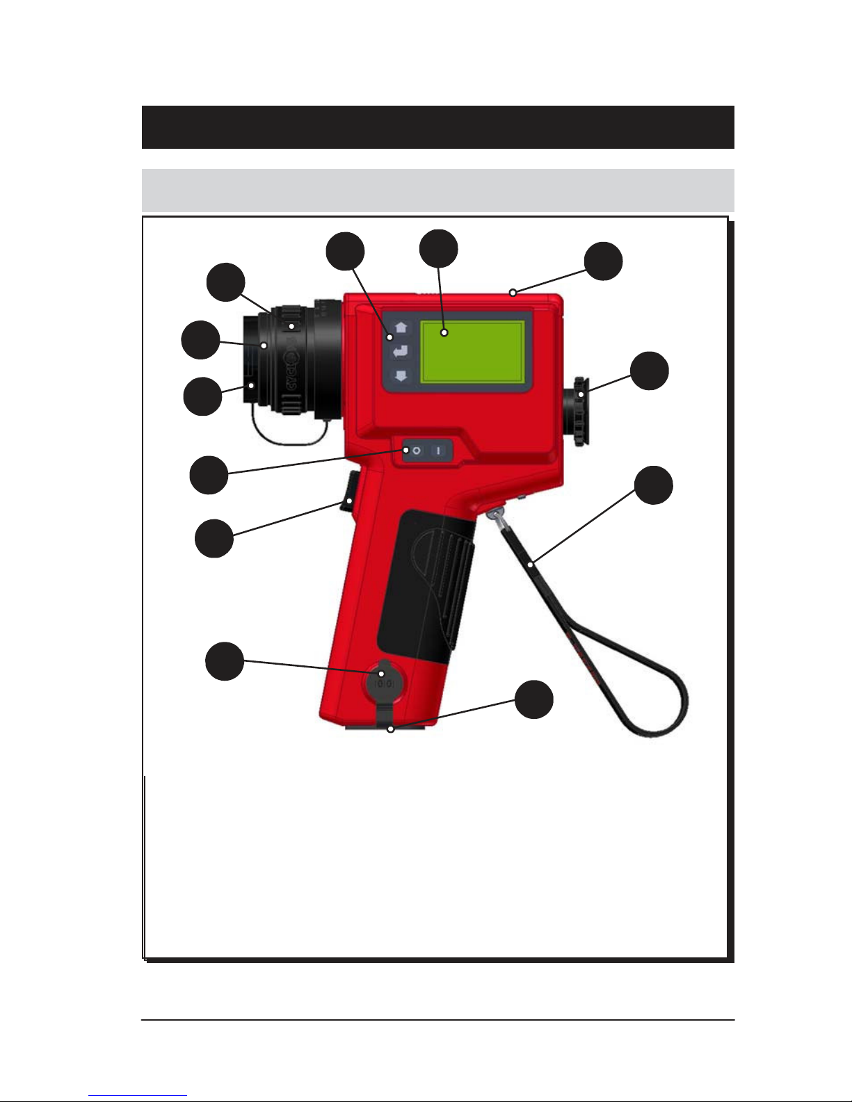
3.0 THERMOMETER DESCRIPTION
3.1 Wahl DHS520/520B
2
1
12
3
4
11
5
6
10
7
8
9
315003
1
LCD display panel
7
Trigger switch (2 position)
2
Keypad
8
External connection cover
3
Optical focusing ring
9
Tripod mounting hole
4
Protective window
10
Adjustable wrist strap
5
Lens cap
11
Adjustable eyepiece
6
ON/OFF switch
12
Battery compartment cover
Fig. 3 Wahl DHS520/520B portable infrared thermometer description
Page 18
Page
6
Wahl DHS520
User Manual
4.0 THERMOMETER POWER SUPPLY OPTIONS
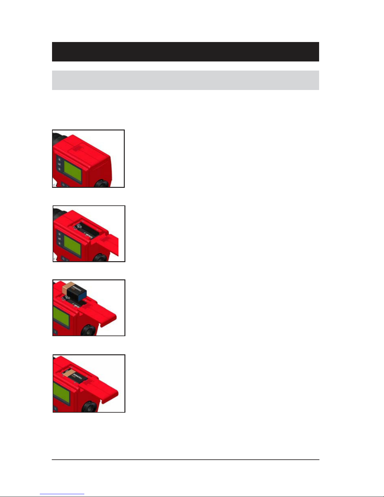
4.1 Using a Battery
The Wahl DHS520/520B portable thermometer is designed to be powered by a
9V dry cell battery. A Duracell 6LR61/12232 (or equivalent) battery is supplied
with the thermometer. The battery is fitted as follows:
Fig. 4
Fig. 5
Fig. 6
Fig. 7
315004
315005
315006
315007
1) Before inserting or changing the battery, ensure
that the thermometer is switched OFF.
2) The battery cover is on the top surface of the
thermometer body (see Fig. 4).
3) Press down on the finger grip of the battery cover
to disengage the cover catch and slide the cover
back to fully expose the battery compartment (see
Fig. 5).
4) A lig n th e bat tery so th at the te rmin als
co rres po nd wi th the la bel i n t he b att er y
compartment (see Fig. 6).
5) Insert the battery, ensuring that the contact springs
engage centrally into the battery terminals. Slide
the battery cover back into place and ensure that
the cover catch engages with the thermometer
chassis (see Fig. 7).
6) With the battery fitted, switch the instrument on
and check for correct operation (see Section 7.0).
When switched on, a battery power indicator
appears in the LCD display panel, which gives an
indication of how much power is left in the battery.
When the battery needs replacing, the battery
indicator on the LCD display panel will flash. To
prolong the remaining battery life, the display
backlight and ‘Bluetooth’ (DHS520B only) should
be switched off. The battery should be changed
as soon as possible in order to ensure that the
readings from the instrument remain within
specification.
Page 19

Page
7
User Manual Wahl DHS520
Note
It is recommended that a fully charged spare battery is kept with
the thermometer at all times.
To preserve battery lifetime, the thermometer has the following power saving
features:
• If the thermometer is in Menu Mode for over one minute without any
key being pressed, the display returns to Measure Mode.
• If the thermometer is in Measure Mode for over two hours without any
key being pressed, the instrument is switched off.
4.2 Using an External Power Source
Although the Wahl DHS520/520B portable thermometer is designed to
be powered by an internal battery, it can be powered by a suitable external
power source (9 to 12V d.c./100mA rated).
Note
If the thermometer is to be used with an external power source,
ensure that the internal battery is removed before applying
external power.
To connect an external power source:
1) Switch off the thermometer and remove the battery.
2) Connect the external power source (9 to 12V d.c./100mA rated) to a
‘HIROSE’ connector (HR10-10P-12P). Connect the ‘positive’ to pin 5
and the ‘0V’ to pin 7.
3) Remove the rubber cover from the external connection socket, located
near the base of the thermometer (see Fig. 3, item 8).
4) Connect the ‘HIROSE’ plug to the external connection socket.
5) Switch the thermometer ‘ON’ and check for correct operation.
Page 20
Page
8
Wahl DHS520
User Manual
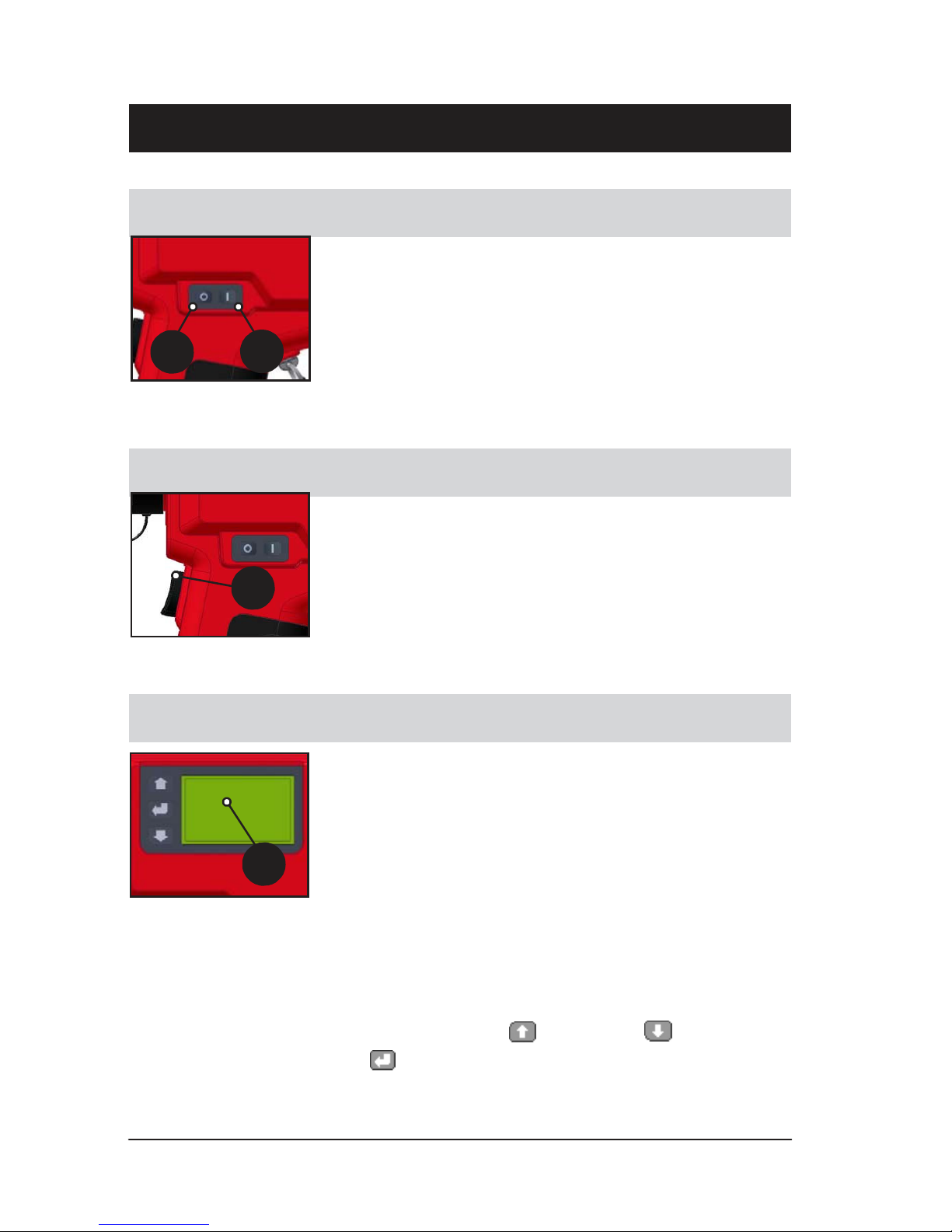
5.0 THERMOMETER CONTROLS
5.1 ON/OFF Switch
a
Fig. 8
315008
b
The On/Off switch is on the left-hand side of the
thermometer (see Fig. 3, item 6). The switch has two
push buttons, Off (a) and On (b).
A single press of the switch will activate/de-activate
the unit.
5.2 Trigger Operation
Fig. 9
315009
c
The Trigger (c) is on the thermometer handle (see Fig.
3, item 7). The trigger function depends upon the
chosen mode of operation: Classic, History or Burst.
In Classic mode, the trigger has one function, to read
and display temperature. In History and Burst modes,
the trigger activates advanced functions within the
thermometer (see Section 8.0).
5.3 LCD Display Panel & Keypad
315010
d
Fig. 10
The LCD display panel (d) is on the left-hand side of
the thermometer body (see Fig. 3, item 1). It operates
in two modes: Measure Mode and Menu Mode.
In Measure Mode, the scene temperature and
thermometer setup information (including battery life
indication) is displayed.
In Menu Mode, the function menus of the thermometer
can be accessed. You can select functions and set
the required parameters, as described in Section 7.0.
There are three action keys on the Keypad to the left
of the main display:
(Scroll Up), (Scroll Down)
and (Enter/select). These are used to navigate
around the various menus and displays.
Page 21

Page 22

Page
10
User Manual Wahl DHS520
5.4 Adjustable Eyepiece
315011
e
Fig. 11
The Adjustable Eyepiece (e) is on the rear face of the
thermometer (see Fig. 3, item 11).
The eyepiece allows you to view the scene being
measured by the thermometer. The eyepiece can be
adjusted manually to match each user ’s eyesight
characteristics (See section 6.6).
5.5 Optical Focus Ring
315012
g
315013
f
Fig. 12
h
Fig. 13
The Optical Focus Ring (f) is on the lens assembly at
the front of the thermometer (see Fig. 3, item 3). The
focus ring allows you to manually adjust the lens
assembly and sharpen the scene in view.
The focal range is 1m/39.4in (as measured from the
instrument datum) to infinity, which equates to
approximately 90° of rotation. The datum mark (h) is
on the instrument label on the right-hand side of the
thermometer.
As standard, the thermometer is supplied with two
protective windows. The clear window is for general
use, and the dark window is for use where temperatures
in the scene are likely to exceed 1200°C/2192°F.
A protective lens cap (g) is supplied and should be fitted
at all times when the thermometer is not in use.
5.6 External Connection Socket
i
Fig. 14
315014
The External Connection Socket (i) is on the left-hand
side of the thermometer handle (see Fig. 3, item 8).
The socket has two main functions: it allows an external
power source to be connected to the thermometer, and
it enables the thermometer to interface with an IPAQ or
laptop, giving datalogging facilities via serial RS232
communications.
The protective rubber cover should be fitted at all times
when the socket is not in use.
Page 23

Page
11
Wahl DHS520
6.0 OPTICS
User Manual
The Wahl DHS520/520B has a precision reflex optical system, which provides
user-focusable ‘through the lens’ sighting and gives precise definition of the
target spot. The specified focal range is 1m/39.4in to infinity.
6.1 Target Size Calculation
The precision reflex optical system gives a narrow field of view (180:1 to 98%
energy).
As the instrument is focusable, you can calculate an approximate target size
from the information given in Fig. 15.
target distance (D) from optical datum
field of view
optical
datum
target size (T)
Not to scale
target diameter (T) (mm) = target distance (D) from optical datum (mm) - 100
field of view (180)
or
target diameter (T) (in) = target distance (D) from optical datum (in) - 4
field of view (180)
315015
Fig. 15 Wahl DHS520/520B thermometer target size calculation
Page 24

Page
12
User Manual Wahl DHS520
6.2 Lens Options
The Wahl DHS520/520B is supplied, as standard, with a protective window
which covers and protects the instrument lens.
Palmer Wahl can supply optional close-up lenses, which enable smaller
targets to be measured.
CAUTION
Never look at the sun through this instrument - this could cause
severe damage to the eye. When measuring temperatures above
1200°C/2192°F, a dark filter must be fitted to the lens assembly.
6.3 Fitting a Close-up Lens
To fit a close-up lens to the Wahl DHS520/520B thermometer, unscrew
the clear protection window from the lens assembly and replace it with the
relevant close-up lens.
The optical transmission characteristics of the protection window and the closeup lens are similar. Therefore, there will be no significant calibration error, so
window compensation is not required.
6.4 Fitting a Dark Filter
When measuring temperatures above 1200°C/2192°F, the image through the
viewfinder is uncomfortably bright on the eye. To counter this effect, a dark
filter must be fitted in place of the clear protection window.
To fit a dark filter to the Wahl DHS520/520B thermometer, unscrew the clear
protection window from the lens assembly and replace it with the dark filter.
The optical transmission characteristics of the protection window and the dark
filter are similar. Therefore, there will be no significant calibration error, so
window compensation is not required.
6.5 Fitting a Dark Filter to a Close-up Lens
When measuring a small target where the temperature rises above 1200°C/
2192°F, the image through the viewfinder becomes uncomfortably bright on
the eye. A close-up lens and a dark filter combination must be fitted in place of
the clear protection window. (Continued...)
Page 25

Page
13
Wahl DHS520
User Manual
To fit a dark filter and close-up lens combination, unscrew the protection window
from the lens assembly and replace it with a close-up lens (first), followed by
a dark filter. As there is now an extra optical element in the sight path of the
instrument, a window compensation factor of 0.93 must be entered to allow
for the associated energy losses.
6.6 Eyepiece Optics
target reticule
(1/3° circle)
Not to scale
display panel
temperature
reading
315016
Fig. 16 Wahl DHS520/520B Eyepiece Optics
The eyepiece allows you to look into the thermometer and view the target
scene. Accurate target definition is provided by the wide angle (9°) field of
view and small, clearly defined (1/3°) target reticule.
The eyepiece can be focused manually to match each user’s eyesight
characteristics:
1) Use the viewfinder to view a plain, brightly lit background, such as a
blank wall.
2) Rotate the rubber eye cup to bring the reticule circle to the sharpest
possible focus. The eyepiece is now adjusted to your eye.
3) Adjust the main focusing ring to bring the target scene to the sharpest
possible focus on the reticule circle.
When a temperature reading is taken (the trigger pressed), the measured
value is displayed in the eyepiece display panel. The temperature is displayed
in the units selected from the Main Menu.
Page 26

Page
14
User Manual Wahl DHS520
7.0 DISPLAY PANEL MODES
7.1 Introduction
The LCD display panel has two basic modes of operation:
• Measure Mode
• Menu Mode
When the thermometer is switched on, an introduction screen is displayed.
This screen times-out automatically and is replaced by the Measure Mode
display.
To access the Menu Mode from the Measure Mode, press the (Enter/
select) key on the keypad.
7.2 Measure Mode
When the unit is in Measure Mode, the display indicates the Peak,
Continuous, Average, and Valley temperature values simultaneously.
Scroll using the and keys to select and highlight the required
measurement type. This measurement type is then displayed in the viewfinder.
On the side LCD display panel, the selected measurement type is displayed
larger and bolder than the three non-selected measurement types. Note that
the thermometer measures in all four measurement types continuously.
Peak reading
Continuous
reading
Average reading
Valley reading
Fig. 17 Typical ‘Measure Mode’ display
315017
Page 27

Page
15
User Manual
Wahl DHS520
7.2.1 Peak temperature measurement
The Peak temperature measurement mode is used to measure and display
information about the highest temperatures recorded by the thermometer.
The peak temperature values can be viewed in the instrument eyepiece and
streamed to the serial or ‘Bluetooth’ outputs.
e
f
g
j
c
d
h
i
b
fluctuating object
a
temperature reading
315018
Fig. 18 Graphical representation of typical Peak temperature measurement
a Thermometer trigger pressed
b Peak temperature value on display jumps to instantaneous temperature
value and rises with rise in object temperature
c Object temperature falls, last Peak temperature value held on display
d New ‘Peak’ temperature value reached, display updated
e Object temperature falls, last Peak temperature value held on display
f Trigger released, last Peak temperature value frozen on display
g Thermometer trigger pressed
h Peak temperature value on display jumps to instantaneous temperature
value (even if lower than last Peak value held before trigger release).
Peak temperature value held on display
i New Peak temperature value reached, display updated as object
temperature rises
j Object temperature falls, last Peak temperature value held on display
Page 28

Page
16
User Manual
Wahl DHS520
7.2.2 Continuous temperature measurement
Continuous temperature measurement provides the real-time observed
temperature value. The temperature is updated continuously and the value is
viewed in the instrument eyepiece.
7.2.3 Averaged temperature measurement
Averaged temperature measurement gives a ‘smoothed’ temperature value. To
use the averaging function, press and hold down the trigger. The averaging
function operates for the period during which the trigger is held down. Averaging
stops when the trigger is released.
The response time of the averaging is controlled by the Averager Time
Constant setting in Menu Mode. The options are Slow, Mid and Fast. Use
the and keys to select the required option from the menu.
With a Fast time constant selected, the temperature reading closely matches
the object temperature. Only the most rapid fluctuations in the input are
smoothed in the output. With a Slow time constant selected, the temperature
reading is much smoother, displaying more of a ‘trend’ value rather than showing
any rapid changes. With a Mid time constant selected, the temperature reading
is calculated somewhere between the fast and slow time constant values.
‘Slow’ averager
time constant
‘Fast’ averager
time constant
‘Mid’ averager
time constant
b
fluctuating object
temperature reading
a
315019
Fig. 19 Graphical representation of typical Averaged temperature
measurement with Slow, Mid and Fast time constants
a Thermometer trigger pressed
b Averaging is initiated at the instantaneous temperature value. Averaged
temperature values are calculated, displayed and updated
Page 29

Page
17
User Manual
Wahl DHS520
7.2.4 Valley temperature measurement
Valley temperature measurement is the inverse of Peak temperature
measurement, in that it allows you to monitor the lowest temperature value
rather than the highest. Temperature measurement starts when the trigger is
pressed in and continues until the trigger is released (See Fig. 20).
The temperature is updated instantaneously and the value is viewed in the
instrument eyepiece. It is also streamed to the serial or ‘Bluetooth’ outputs (if
fitted).
fluctuating object
temperature reading
g
h
b
c
e
d
f
a
315020
Fig. 20 Graphical representation of typical Valley temperature measurement
a Thermometer trigger pressed
b Valley temperature value on display jumps to instantaneous temperature
value and is held on display with rise in object temperature
c Object temperature falls, new Valley temperature value reached, display
updated as object temperature falls. Object temperature rises, last
Valley temperature value held on display
d Object temperature falls, new Valley temperature value reached, display
updated as object temperature falls. Object temperature rises, last
Valley temperature value held on display
e Trigger released, last Valley temperature value frozen on display
f Trigger pressed
g Valley temperature value on display jumps to instantaneous temperature
value (even if higher than last Valley value held before trigger release).
Display updated as object temperature falls
h Object temperature rises, last Valley temperature value held on display
Page 30

Page
18
Wahl DHS520
User Manual
7.3 Menu Mode
When the thermometer is in Menu Mode, the menu options available in the
Wahl DHS520/520B thermometer can be accessed. This allows you to
view and configure the setup of the thermometer and select the options that
best suit your temperature measurement requirements.
At start-up and during normal operation, the thermometer is in Measure Mode.
1) To access Menu Mode press the key.
The main menu options are displayed as icons. There are 11 main
menu options, although only 8 icons are displayed within the screen at
any one time (See Fig. 21).
2) Use the and keys to scroll through the menu options. The
currently selectable menu item is highlighted by a ‘flashing’ frame.
3) To select a menu option, press the key.
When a main menu option is selected, the available sub-options are
displayed.
4) Use the and keys to highlight the required sub-option in the
menu. Press the key to select it.
5) For sub-options where a numeric value is required, use the scroll keys
to select the required numeric value, then click on the key to set this
value. For example, to change the emissivity from 1.00 to 0.78, select
the Emissivity menu, then press and hold in the key to change the
value from 1.00 to 0.78. If you ‘overshoot’ the value, use the key to
return to the required value
6) When you have set a required parameter value, press the key to
return to the main menu options.
Fig. 21 Typical ‘Menu Mode’ screen display
315021
Page 31

Page
19
User Manual Wahl DHS520
7.4 Menu Mode - Icon Descriptions
The information in this chapter should be used in conjunction with the
navigational flow chart (see Fig. 22).
(a) Exit
When in Menu Mode, clicking on the exit icon (a) will
return you to Measure Mode. The icon is also used in
History Mode setup, to return back to Trigger Mode.
(b) Emissivity
Clicking on the emissivity icon (b) will open a screen in
which the emissivity value can be set. Use the and
keys to enter t he r equired value. For a
comprehensive list of emissivity values, see Section
11.0 - Emissivity. The default value is 1.00.
(c)
(d) (e)
Trigger Mode
The trigger mode determines the way in which the thermometer operates,
and what happens to the readings taken by the instrument. The are
three trigger modes: Classic (c), Burst (d) and History (e). See Section
8.0 - Operational (Trigger) Modes. The default trigger mode is Classic.
(f)
(g)
(h)
Alarms
The alarms function allows you to specify alarm values for the scene
under observation. The function has three sub-options: High Alarm (f),
Low Alarm (g) and Alarm Off (h). When high or low alarms are selected,
a value setting screen appears. Use the and keys to enter the
alarm trigger temperature. The default setting for High and Low alarm is
the thermometer mid-range value.
Page 32

Page
20
Wahl DHS520
User Manual
(i) (j) (k)
Averager time constant : the averager time constant function allows you
to set the rate of averaging of the temperature values taken. There are
three options: Fast (i), Mid (j) and Slow (k). The default setting is Mid.
(l) (m)
(n)
(o)
Units
This menu allows you to select the unit of measurement. There are four
options: °Celsius (l), °Fahrenheit (m), °Rankine (n) and Kelvin (o). The
default setting is °C.
(p) (q)
(r)
Backlight
This option allows you to control the brightness of the side display
backlight. There are three backlight options available: High (p), Low (q)
and Off (r). When High or Low are selected, a sub-menu appears in
which you can specify a time limit (in seconds) after which the backlight
turns off if the thermometer is inactive. The default setting is Off.
Note: Use of the backlight will reduce the life of the battery. It is
recommended that the backlight is switched off when not required.
Page 33

Page
21
User Manual Wahl DHS520
(s) (t)
Sounder
This option allows you to either switch on or mute the sounder. When
switched on, the sounder indicates trigger operation, alarm trip, active
communications response, and los t communications response
(Bluetooth). The available sounder options are: Sounder On (s), or
Sounder Off (t). The default setting is On.
(u) (v)
Window compensation
This function allows you to manually incorporate a known compensation
value into the temperature calculation, which allows for the reflectivity of
unusual combinations of thermometer windows. This function can be
selected On (u) or Off (v).
If you switch the function On, a screen is displayed in which you can set
the required window compensation. Use the and keys to adjust
the value. The default setting is 1.000.
Examples:
Clear protection window fitted : Window compensation Off
Dark eye comfort filter fitted : Window compensation Off
Close-up lens fitted : Window compensation Off
Eye comfort filter and Window compensation On
close-up lens fitted : Value set to 0.93
Any combination of the Window compensation On
above and an external value to be determined practically
viewing window into the
customer process :
Page 34

Page
22
Wahl DHS520
User Manual
(w)
About
This function (w) accesses general information about the product. The
details displayed include: calibration information, thermometer serial
number, Bluetooth identifier (for Bluetooth models), software version,
Tmax and Tmin ambient temperature readings since last calibration and
a link to the Palmer Wahl website.
(x) (y)
Bluetooth
Bluetooth communications allow wireless streaming of information from
the thermometer to a remote facility. This function is only available in
Bluetooth enabled models. The Bluetooth communication function can
be set to On (x) or Off (y). The default is Off.
Note that with Bluetooth switched On, the life of the battery will be reduced.
It is recommended that this function is switched Off when not required.
The complete set of menu options is indicated as a flowchart shown in
Fig. 22.
Page 35

User Manual Wahl DHS520
Page 22 (Blank)
Page 36

Page
23
++
Use
r
Guide
MEAS URE MOD E
EXIT
EMI SSIVITY
=
1.00
BURS T MOD E
TRIG GER MOD E
ALARM S
AVE RAGER TIME
CONS TANT
UNI TS
BAC KLIGHT
HIS TORY MOD E
CLAS SIC MOD E
OFF
HIGH
ALARM
LOW
ALARM
FAS T
MID
SLOW
°C
°F
°R
K
HIGH
LOW
OFF
1800 °C
1800 °C
10s
ON
SOU NDER
WIND OW
COM PENSAT ION
Bluetoo th not fitte d
ABO UT
OFF
ON
OFF
PRODUCT INFORMATIO N
APPROVALS, CALIBRATION, SERIAL NUMBER, BLUETOOTH
IDENTIFIER, SOFTWARE VERSION, AMBIENT TEMPERATURE S
(TMAX/TMIN) SINCE LAST CALIBRATION, WEBSITE LINK
1.00 0
Peak Temp. Value (units)
Continuous Temp. Value (units)
Average Temp. Value (units)
Valley Temp. Value (units)
KEY
TOP LEVE L MEN U
SUB MEN U
SUB MENU ACTI ON/
SET VALU ES
DEFA ULTS (FAC TORY SET)
DEFA ULT ICO N
20s
DEFA ULT VALU E
SCROLL UP
SCROLL DOWN
ENTER
_ _ _ _ (units)
_ _ _ _ (units)
_ _ _ _ (units)
_ _ _ _ (units)
BLUE TOOTH
Blueto oth fitted
ON
OFF
315022
Fig. 22 - Wahl DHS520/520B Icon navigational flow chart
Page 37

Page 38

Wahl DHS520
Page 24 (Blank)
User Guide
Page 39

User Manual Wahl DHS520
Page 40

Page 41

User Manual Wahl DHS520
Page
25
8.0 OPERATIONAL (TRIGGER) MODES
8.1 Introduction
The Wahl DHS520/520B thermometer has three operating modes:
• Classic
• History
• Burst
The thermometer trigger is used to control
the operation of the thermometer in each
mode. The trigger has two stages: T1 and
T2 (See inset).
A light press on the trigger will move it to
position T1, at which point a stronger press
will be required to move the trigger a small,
further distance to the second position T2.
This section of the user guide describes
the measurement and data collection
options available by using the two-stage
trigger functions.
T r i g g e r
released
T2
T1
8.2 Classic Mode
Classic Mode is the simplest operating mode and the one that most closely
resembles the operation of earlier Wahl portable thermometers.
In Classic Mode, the trigger operation is single stage (T1) only. However, note
that in Classic Mode, moving the trigger to the T2 position has no further effect.
All four measured temperature types (Peak, Continuous, Average and Valley)
are displayed on the side LCD panel, although only the highlighted temperature
type is displayed in the viewfinder and streamed serially to the DA-
LOG datalogging software (wired connection or via Bluetooth). Data is
streamed in
0.5s intervals when the trigger is pressed in. When the trigger is released,
streaming stops and the temperature is logged.
Page 42

Page 26
Wahl DHS520
8.3 History Mode
In History mode all data collection and transfer is controlled by the dual stage
trigger operation. In summary, the T1 position is used to align the instrument
on the chosen target and the T2 position is used to generate the logged data.
With the trigger pulled to the T1 position, operation is exactly the same as in
Classic mode. All four temperature types (Peak, Continuous, Average and
Valley) are displayed with the selected (highlighted) type being displayed
internally within the viewfinder as well as being streamed serially in 0.5 second
intervals (wired connection or Bluetooth).
If the trigger is pulled to the T2 position, this is confirmed by a single ‘blink’ on
the internal viewfinder, coupled with a single ‘beep’ on the sounder (if switched
on). When the trigger is pulled to the T2 position, both the viewfinder and side
displays are ‘frozen’ and a ‘packet’ of data is generated and sent out for data
logging. This packet of data comprises the overall peak, last continuous,
overall average and overall valley temperature measurements taken during
the time that the trigger was pressed to the T1 position. The emissivity set
point and window compensation indicator value in use are also output, as part
of the data packet.
The temperature components of this data packet are also retained within the
instruments memory and may be viewed on the side display by going into
Menu mode and re-selecting twice on the History mode icon.
Note that further data packets will only be added after each press of the trigger
to the T2 position and the data added will be the measurements made at the
T1 position during the time preceding the press to T2. Any measurement
made at the T1 position without going to the T2 position will not be stored.
If additional data is added, any higher peak (or lower valley) temperature
recorded will overwrite the earlier stored value. The new average value will
then become the average over all stored data and the continuous value
displayed will become an average of the last continuous values for each data
packet within the overall stored sets.
When the stored data set has been inspected the user has the option of deleting
the data by selecting the ‘waste basket’ icon, or exiting the data set without
deletion (exit icon) in which case further data may be added to the stored set.
Note
If the instrument is switched off, all stored data will be lost.
Page 43

User Manual Wahl DHS520
Page
27
8.4 Burst Mode
Burst mode is only intended for use when data logging to an IPAQ or laptop
computer.
It can be used for monitoring rapid fluctuations of temperature or recording a
temperature profile, such as a long strip of material.
Burst mode requires dual stage trigger operation. With the trigger pulled to
the T1 position, the instrument operates as per Classic mode (See Section
8.2). However, note that that in burst mode, the instantaneous readings (only)
are always highlighted on the side screen and displayed internally within the
viewfinder.
When the trigger is pulled to the T2 position, live temperature data (only) is
streamed at the maximum collection rate (approximately 33 readings per
second) to the serial port and the Bluetooth module. This mode of operation is
denoted by the internal display ‘blinking’ in unison with the sounder ‘beeping’
(if switched on) at approximately 0.5 second intervals.
When the trigger is released, a 2-piece data packet is added, giving the
emissivity and window transmission factor values.
Note that when logging to the DA-LOG software, the maximum number of
consecutive readings that can be stored in each file is limited to 999 - equating
to 30 seconds of Burst mode output.
If the trigger is released back to the T1 position, Classic mode operation is
resumed.
Page 44

Page 28
Wahl DHS520
9.0 THERMOMETER OPERATION
User Manual
CAUTION
Never look at the sun through this instrument - this could
cause severe damage to the eye.
When measuring temperatures above 1200°C/2192°F, a dark
filter must be fitted to the lens assembly.
Prior to temperature measurement, the thermometer must be set up as dictated
by the chosen application.
The setup procedure can be split into three different setup groups:
• Data Output Setup
• User Interface Setup
• Measurement Setup
The following list details the setup groups and the available selections.
Setup Group
Function
Selection Options
Data Output Setup
Trigger Mode
Classic / History / Burst
Bluetooth
On / Off
User Interface Setup
Trigger Mode
Classic / History / Burst
Backlight
High (enter timer value)
Low (enter timer value)
Off
Sounder
On / Off
Alarms High Alarm
(enter set-
Low Alarm
Off
point values)
Measurement Setup Units °C / °F / K / °R
Emissivity (0.01 to 1.20)
Averager Time Constant Fast / Mid / Slow
Window Compensation On (0.80 to 1.20) / Off
Page 45

Page 46

Page 30
Wahl DHS520
User Manual
9.1 Operation (Example 1: simple temperature measurement)
1) Switch the thermometer on via the On/Off switch. The initialization
screen will appear and, after a few seconds, the screen will change to
show the measurement mode display.
2) Check the battery status, ensure that there is sufficient battery life
remaining.
3) Assess the intended target. If the target temperature is likely to be
above 1200°C/2192°F, fit the dark window (supplied as a standard
accessory). Refer to Section 6.4.
4) If the trigger mode is not already set to Classic Mode, go
into Menu Mode, open the Trigger Mode menu and select
Classic Mode
5) Enter the Emissivity value for the material under observation (refer to
the tables in Section 11.0).
6) Ensure that Window Compensation is Off.
7) Ensure that the Alarms function is set to Off.
8) Ensure the Bluetooth option is set to Off (Wahl DHS520B variants only).
9) On the side display, select the Continuous temperature measurement
option (see Section 7.2).
10) Adjust the eyepiece to suit the user (See Section 6.6), then aim the
thermometer at the target and, using the lens focus adjustment (See
Section 5.5), focus the reticule onto the area under observation. Check
that the reticule is fully filled by the target, re-position if necessary.
11) Press the trigger to start measurement. The main display and eyepiece
display are updated with the reading
12) Release the trigger to stop measurement and freeze the last recorded
value on the main display.
Page 47

Page
31
User Guide
Wahl DHS520
9.2 Operation (Example 2 : complex temperature measurement)
In some industrial applications, a window or viewing port may be situated
between the thermometer and the target object. This can lead to a reduction
in the amount of radiant energy reaching the thermometer from the target.
The following instructions detail the operation of a Wahl DHS520/520B in a
typical complex temperature measurement application (as in Fig. 23).
1
2
1
Viewing port/window: Glass - typical window compensation factor
(0.920)
2
Hot target: Mild steel - typical emissivity value (0.35)
315023
Fig. 23 Typical complex temperature measurement application
Page 48

Page 32
User Guide Wahl DHS520
1) Check the battery status, ensure that there is sufficient battery life
remaining
2) Assess the intended target. If the target temperature is likely to be
above 1200°C/2192°F, fit the dark window (supplied as a standard
accessory)
3) Go into Menu Mode, open the Trigger Mode menu and select Classic
Mode
4) Enter the ‘Emissivity’ value for the material under observation (0.35)
If the window compensation factor of the viewing window/port is known:
5) Set Window Compensation to On.
6) Enter the known compensation factor (0.920)
If the ‘Window Compensation’ factor of the viewing window/port is not known:
7) Take and record a reading with the thermometer of a known temperature
value, with the emissivity set to correspond and the Window
Compensation factor set to default (i.e. blackbody heat
source, emissivity set to 1.00 and Window Compensation set to
1.000).
8) Place a spare viewing window/port between the thermometer and the
blackbody heat source and take a new temperature reading.
9) Enter the Window Compensation > On sub-menu and amend the
Window Compensation factor value with the and keys until the
display temperature reads the same as the recorded value taken from
the known value source. You must now use this Window
Compensation value, as it is correct for the chosen viewing window/
port material (0.920)
10) Ensure that the Alarms function is set to Off.
11) Ensure the Bluetooth option is set to Off (Wahl DHS520B variants only)
12) Select the Continuous temperature measurement option.
13) Aim the thermometer through the viewing window/port at the target and
focus the reticule onto the area under observation. Check that the
reticule is fully filled by the target, re-position if necessary
14) Press the trigger to start measurement. The main display and eyepiece
display are updated with the reading.
15) Release the trigger to stop measurement and freeze the last recorded
value on the main display.
Page 49

Page
33
User Manual
Wahl DHS520
10.0 DATA STREAMING
Data streaming provides flexibility in the retention of information captured by
the thermometer. It can be used in two separate ways: serially or wireless.
10.1 Serial Communications
To capture information from the Wahl DHS520 to a laptop/PC/Pocket PC,
DA-LOG Datalogger Software
must be used.
Note
The ‘Bluetooth’ option must be disabled prior to using wired serial
communications from a Wahl DHS520B thermometer variant.
1) Switch off Bluetooth communication (Wahl DHS520B variants only).
2) Ensure that the datalogging software has been loaded to the PC/laptop
or Pocket PC as required.
3) From the Wahl DHS520/520B, connect the serial cable to the
PC/laptop, or the Pocket PC as required.
4) Select the required Trigger Mode on the Wahl DHS520/520B.
5) Press the trigger to capture and stream data, release the trigger to stop.
Note
To prolong b atte ry lif e, always disconnect t he seri al
communications cable when not in use.
Page 50

Page 34
User Manual
Wahl DHS520
10.2 ‘Bluetooth’ Wireless Comms (Wahl DHS520B variants only)
To capture information by Bluetooth communication from the Wahl DHS520B
to a laptop/PC/Pocket PC, you must use DA-LOG Datalogger Software.
1) Ensure that the datalogging software has been loaded to the PC/laptop
or Pocket PC as required.
2) Establish Bluetooth communications from the Wahl DHS520B to a
laptop/PC/Pocket PC.
3) When Bluetooth communications is active, the Bluetooth logo on the
thermometer side display holds steady and a I0I0I icon appears (a
flashing logo indicates lost Bluetooth communications).
4) Select the required Trigger Mode on the Wahl DHS520/520B.
5) Press the trigger to capture and stream data, release the trigger to stop.
Note
To prolong b atte ry lif e, always disconnect t he seri al
communications cable when not in use.
Page 51

Page 52

Page 36
Wahl DHS520
User Manual
11.0 EMISSIVITY
In order to obtain accurate temperature measurements, the emissivity value of
the target surface must be known. This section of the User Guide contains
typical emissivity values of the most commonly measured materials for each
thermometer variant.
Where no emissivity value is quoted, this means that either the thermometer
is not suitable for the measurement application, or the temperature of the target
is outside the thermometer's measurement span. If you have a query regarding
the emissivity of the target in your measurement application, contact
Palmer Wahl for assistance.
11.1 Refractories
Material Wahl DHS520/520B
Alumina 0.30
Brick Red 0.80
White refractory 0.30
Silica 0.30
Sillimanite 0.60
Ceramics 0.40
Magnesite -
Fig. 24 Typical Emissivity Values for Refractories
315024
Page 53

Page
37
User Manual Wahl DHS520
11.2 Alloys
Material Wahl DHS520/520B
Brass 0.20
Oxidized 0.70
Chromel & Alumel 0.30
Oxidized 0.80
Constantin & Manganin 0.25
Oxidized 0.65
Inconel 0.30
Oxidized 0.85
Monel 0.25
Oxidized 0.70
Nichrome 0.30
Oxidized 0.85
Fig. 25 Typical Emissivity Values for Alloys
Page 54

Page 38
Wahl DHS520
User Manual
11.3 Metals
Material
Wahl DHS520/520B
Aluminum
0.13
Oxidized
0.40
Chromium
0.43
Oxidized
0.75
Cobalt
0.32
Oxidized
0.70
Copper
0.06
Oxidized
0.85
Gold
0.05
Iron & Steel
0.35
Oxidized
0.85
Lead
0.35
Oxidized
0.65
Magnesium
0.27
Oxidized
0.80
Molybdenum
0.33
Oxidized
0.80
Nickel
0.35
Oxidized
0.85
Palladium
0.28
Platinum
0.27
Rhodium
0.25
Silver
0.05
Oxidized
0.10
Tin
0.40
Oxidized
0.60
Titanium
0.55
Oxidized
0.80
Tungsten
0.39
Zinc
0.50
Oxidized
0.60
Fig. 26 Typical Emissivity Values for Metals
315026
Page 55

Page
39
User Manual Wahl DHS520
11.4 Miscellaneous
Material
Wahl DHS520/520B
Asbestos
Board/paper/cloth
0.90
Asphalt
0.85
Carbon
Graphite
0.85
Soot
0.95
Cement & Concrete 0.65
Cloth
All types - close weave
0.75
(Open weave reduces emissivity)
Glass
3mm thick
-
6mm thick
-
12mm thick
-
20mm thick
0.80
Fig. 27 Typical Emissivity Values for Miscellaneous Materials
315027
Page 56

Page 40
Wahl DHS520
User Manual
12.0 MAINTENANCE
The Wahl DHS520/520B thermometer has been designed specifically to require
very little maintenance. There are several processes that are recommended
to help ensure that the instrument remains serviceable.
• Ensure that the lens cover is fitted when the thermometer is not in use.
• Ensure that the lens assembly, eyepiece and display panel are kept
clean and free from contaminants. On a regular basis, clean these
components carefully with a soft lens cloth and proprietary lens cleaner.
• Check the thermometer for damage regularly. Pay particular attention
to the lens assembly, eyepiece, display panel, trigger and on/off switch.
• Ensure that a spare, fully charged battery is kept with the thermometer
at all times.
In the unlikely event of an instrument fault, do not attempt to investigate or
repair the fault on-site. Contact Palmer Wahl to arrange a repair.
Page 57

Page
41
User Manual Wahl DHS520
13.0 ACCESSORIES
13.1 Accessories
Type 110 & Type 135 Close-up Lenses
Type 110 (L-110) and Type 135 (L-135) close-up lenses enable the Wahl
DHS520/520B to focus on targets at distances that are too close to measure
with the standard lens.
The Type 110 (L-110) lens has a fixed focus at 215mm/8.5in, with a
minimum target size of 0.4mm/0.016in. A typical application for this lens is
hot filament/wire observation.
The Type 135 (L-135) lens has a focus range of 450mm/17.7in to
620mm/24.4in, with a minimum target size of 1.8mm/0.07in. A typical
application for this lens is calibration on small aperture furnaces.
315028
Fig. 28 Type 110 and Type 135 close-up lenses
Page 58

Page 42
User Guide Wahl DHS520
Protective Hard Carry Case
The Hard Carry Case (DA-WPC) is a rugged, lightweight, waterproof
and shockproof injection-molded box, giving full environmental protection.
It is supplied with custom-cut foam cushioning, with cut-outs for the
thermometer and any supplied accessories, allowing all items of the ‘kit’ to be
kept together for convenience.
Dimensions: 14.2 x 11.4 x 6.5in/360 x 290 x 165mm (width x length x depth)
315029
315030
Fig. 29 Hard carry case (closed) Fig. 30 Hard carry case (open)
Page 59

Page
43
User Manual Wahl DHS520
Page 60

Page 44
Wahl DHS520
User Manual
14 USER CONFIGURATION RECORD
The Wahl DHS520/520B can be configured to suit your measurement
requirements. Your chosen parameter settings and values are stored in the
thermometer’s memory.
If the thermometer is returned to Palmer Wahl for repair or recalibration, it
is possible that your stored user settings may be overwritten and the
thermometer returned to you with the factory default settings.
Therefore, it is recommended that once you have set up the thermometer to
match your measurement requirements, you use the User Configuration Record
(overleaf) to make a note of your chosen parameter settings and values, so
that these can be re-entered into the thermometer and used again.
Page 61

Page
45
User Manual Wahl DHS520
USER CONFIGURATION RECORD
Serial Nº .............................................................
Date: .............................................................
Measurement Mode: Peak
Instantaneous
Averaged
Valley
Menu Mode: Emissivity (value) ....................
Data Output Mode: Classic
Historic
Burst
Alarm Settings: Alarm off
High alarm
(value) ....................
Low alarm
(value) ....................
Averager setting: Slow
Mid
Fast
Temperature units: °C
°F
K
°R
Backlight Setting: Off
Dim
(timer) ....................
Bright
(timer)
....................
Sounder Setting: Off
On
Window transmission: Off
On
(value) ....................
Page 62

Page 46
Wahl DHS520
User Manual
APPENDIX
Serial Communications Data Logging Protocol
T
he logging protocol applies to both the SERIAL PORT and BLUETOOTH module.
UART Settings
BAUD 57600 fixed
START DATA PARITY STOP1,8,N,1
Classic Mode stream
When the trigger is pressed to the T1 position, a continuous stream of lines of data
of fixed (12 character) length is output every 0.5 ±0.1seconds.
EXAMPLE:
B C C I +972.0 CR LF
(i) Identifier B = C100
D
= C055
(ii) Packet
C
Classic – while key pressed
H
Hold – when key released
(iii) Units
C
°Celsius
F
°Fahrenheit
R
°Rankin
K
Kelvin
(iv) Mode
I
Instantaneous
P
Peak
V
Valley
A
Average
(v) Data In tenths up to ±999.9
In degrees after ±1000
Over-range is ± _ _ _ i.e. 0xAF,SP, 0xAF,SP, 0xAF
Under-range is ±_ _ _ i.e. 0x5F,SP, 0x5F,SP, 0x5F
(vi) Termination 0x0D,0x0A
The IPAQ sends a * handshake to indicate ‘H’ hold – i.e. key released and data
logged
.
Page 63

Page
47
User Manual Wahl DHS520
Page 64

Page 48
Wahl DHS520
User Manual
Advanced Mode - data stream
When the trigger is pressed to the T1 position, a continuous stream of lines of data
is produced every 0.5 ±0.1seconds:
B 1 C I +972.0 CR LF
As per Classic Mode stream except
(i) Packet
1
Advanced mode - trigger 1 pressed
There is no handshaking of the advanced data stream.
Advanced – History mode packet
When the trigger is pressed to the T1 position, a 6 line packet of calculated data is
output.
EXAMPLE:
B 2 C
I
+972.0
CR
LF
B 2 C P +1030 CR LF
B 2 C V
+812.0
CR LF
B 2 C A
+900.0
CR LF
B 2 C E
+1.000
CR LF
{ B 2 C T
+1.000
CR LF
or if disabled
{ B 2 C T +
OFF
CR LF
As per Advanced Mode - data stream except:
(i) Packet
2
Advanced – History mode packet
(ii) Mode
E
Emissivity
T
Window Transmission
(iii) Data In thousandths for emissivity/transmission
The IPAQ should send a * handshake to indicate packet reception.
Advanced – Burst Mode packet
When T2 is pressed in burst mode, a continuous stream of lines of data is output
every 30 ±5ms. Example:
B 3 C I +972.0 CR LF
As above except:
(i) Packet
3
Advanced - Burst mode packet
When T2 is released in burst mode, a 2-line termination packet is output:
B 3 C E +1.000 CR
LF
{ B 3 C T +1.000 CR LF
or if disabled
{ B 3 C T + OFF CR LF
The IPAQ should send a * handshake to indicate termination packet reception.
Page 65

Page
49
Wahl DHS520
User Manual
Advanced – Bluetooth Heartbeat
To maintain the Bluetooth link, and to establish that the logger program is running, the
following dummy data can be sent:
B 0 C x xxxxxx CR LF
The IPAQ should send a * handshake to indicate heartbeat reception.
 Loading...