

Page 1
DST600 • DST610 • DST620 Series
Digi-Stem
Thermometer
User Manual
04/12/12
WD1032 Rev G
For use with model:
DST600, DST600R,
DST600I, DST610,
DST611, DST620 &
DST621
Wahl Instruments, Inc.
234 Old Weaverville Road
Asheville, NC 28804
Toll Free 800-421-2853
Phone 828-658-3131
Fax 828-658-0728
www.palmerwahl.com
Page 2

DST600 • DST610 • DST620 Series USER MANUAL
WARRANTY & CALIBRATION
Index
1. Application and Key Features _________________________________________ 2
2. CE Approval _______________________________________________________ 3
3. Installation ________________________________________________________ 3
4. Battery Installation / Replacement / Battery Life ___________________________ 6
5. Operation _________________________________________________________ 7
6. Calibration ________________________________________________________ 9
7. Specifications – DST600 _____________________________________________ 10
8. DST610, DST611, DST620 and DST621 ________________________________ 11
9. Specifications – DST610, DST611, DST620, DST621 ______________________ 15
10. Service ___________________________________________________________ 16
Registration is fast and easy. In about a minute you
can have your product automatically registered for
Warranty Protection and our Calibration Reminder
service. Let Palmer Wahl help you protect your
investment, and maintain product accuracy and
compliance with ISO and other quality standards.
Questions? Call Customer Service
at 1-800-421-2853 or 828-658-3131
Or email: register@palmerwahl.com
REGISTRATION at
www.palmerwahl.com/register
1. Application and Key Features
The Wahl DST600 is designed for temperature monitoring applications,
specifically in the food, dairy and pharmaceutical markets, however it is well
suited for any application requiring a high degree of accuracy and reliability. To
achieve this objective the DST600 incorporates the following features:
• High reliability, 4-wire, 100 ohm, .00385Ω/Ω/°C, thin-film platinum RTD
sensor per DIN EN 60751, Class A.
• High accuracy 24-bit Delta-Sigma Analog/Digital Converter.
• Self-checking Electronic Circuitry: Meter repetitively checks the electronics
accuracy by measurement of on-board ultra-stable, low ppm precision
resistors against embedded firmware values and displays “err” in the event
the electronics is out by more than ±0.5°F (0.3°C). The self-checking
electronic circuit may be tested by rapidly changing the temperature of the
sensor, such as placing from room temperature into ice bath or heated
process. Unit will display “err” occasionally when going through rapid
changes and will return to normal as temperature begins to stabilize (usually
2 of 16
Page 3

DST600 • DST610 • DST620 Series USER MANUAL
within 10° of final temperature). This serves as a test and indicator that the
self-checking circuitry is functioning properly.
• Probe Error checking: Checks for open wire, open sensor, shorted sensor,
incorrect wiring.
• Probe ID feature: Alerts the operator that the probe has been changed and
the calibration may be void. Requires the use of calibration software to
calibrate and associate the new probe with the meter. Available on fixed
stem and remotes less than 25 meters.
• Programmable R0: Allows programming of the sensing probes specific R0
value into the meter for accurate temperature calibration.
2. CE Approval
The DST600 carries CE approval per EN61326: 2006 for Radiated
Electromagnetic Field Immunity, Electrostatic Discharge Immunity and Radiated
Emissions Disturbances. See sections 3.4 and 3.5 for detailed installation
instructions.
3. Installation
Caution! See important information regarding Lithium Batteries on the
enclosed document #WD1053, before proceeding!
Your unit was shipped partially assembled. Installation of the battery by the enduser is necessary as transportation regulations prohibit shipping units with the
battery installed. Units with long probes or remote cables may be shipped
unassembled. After installation of the battery, verify the display is operational
and remove the protective film from the window. In the event the display is not
operational, check that the battery is installed properly by following the battery
installation procedure, section 4.
3.1. Meter Mounting – Fixed Probe
Fixed probes may be mounted by the threaded fitting or sanitary clamp into
the process. Apply thread sealing compound or Teflon tape to the threaded
fitting as required. Units with swivel nut fittings or adjustable angle stems
may be adjusted after installation for best viewing angle.
Caution! Do not rotate Digi-Stems with adjustable angles more than 360° in
one direction as wire breakage may occur. See 3.7 for adjustment procedure.
Caution! Do not use the Digi-Stem enclosure to tighten meter. Use a wrench
on the coupling nut for tightening.
3.2. Meter Mounting – Remote Probe
An optional mounting bracket is available for mounting remote meters to
walls, panels, pipes, etc. The mounting bracket may be attached by the top
or rear surface with user provided mounting screws, clamps, etc. The
mounting bracket is available in 2 styles, p/n DSA3030, without ground lug
and DSA3031, which includes a grounding lug for grounding of the meter
when the probe will not be grounded.
3 of 16
Page 4
DST600 • DST610 • DST620 Series USER MANUAL
P1 Pin
Signal Name
Fixed Probe
Remote Probe
1 Excite +
White
Brown
2 RTD +
White
White
3 RTD
- Black
Blue
4 Excite
- Black
Black
5 Probe ID Ground
Brown
Gray
6 Probe ID Signal
Orange
Pink
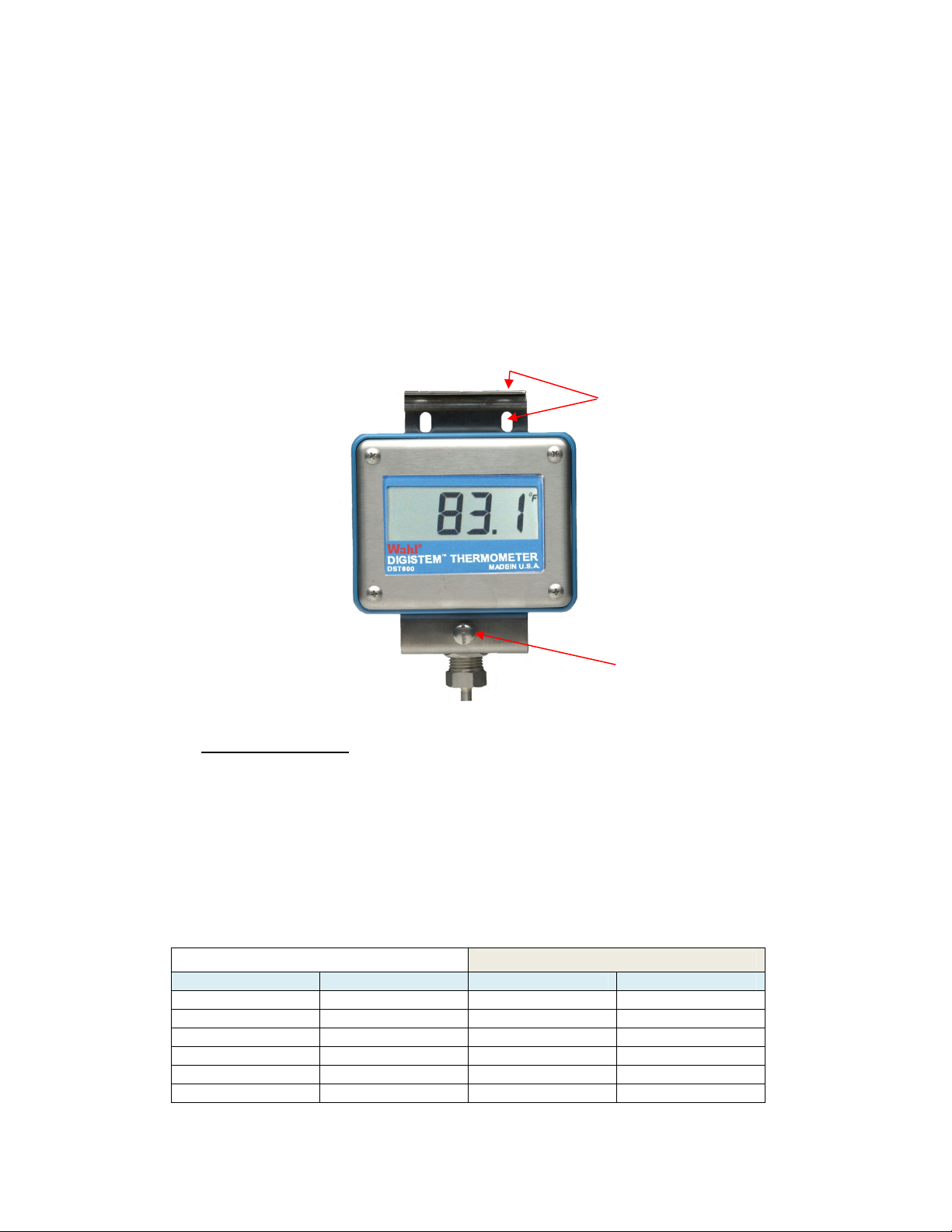
3.2.1. For remote mounting: Mount the bracket with the Digi-Stem
mounting screw towards the bottom (Fig. 1). The Digi-Stem’s
coupling nut should be inserted from the top, with the display facing
out and secured with the Digi-Stem mounting screw. Loosen or
remove the Digi-Stem mounting screw.
3.2.2. For remote cables, thread the cable through the slotted sections of
the mounting bracket holes, so the cable moves freely. Insert the
meter’s coupling nut through the top hole of the mounting bracket and
secure with the large slotted Digi-Stem mounting screw.
Bracket Mounting
Holes
Fig. 1
Digi-Stem
Mounting Screw
3.3. Wire Connections – In the event that your probe was shipped
disconnected from the meter, the following describes the probe wiring and
installation process.
3.3.1. Loosen the four phillips head screws in the front cover until the
cover is removed. Note: The screws are held captive by retaining
washers and should not be removed completely.
3.3.2. Remove the 6 pin pluggable terminal strip connector (J1) from the
PCB mating connector and connect probe wires per the following
table and as shown in Fig. 4.
Probe Connection Wiring Wire Color
4 of 16
Page 5
DST600 • DST610 • DST620 Series USER MANUAL
3.3.3. Connect pluggable terminal strip to PCB connector J1.
3.3.4. Install battery with polarity as indicated on battery holder.
3.3.5. Replace cover on Digi-Stem enclosure and secure with four screws
tightened to a force of 4 to 5 in-lbs. of torque.
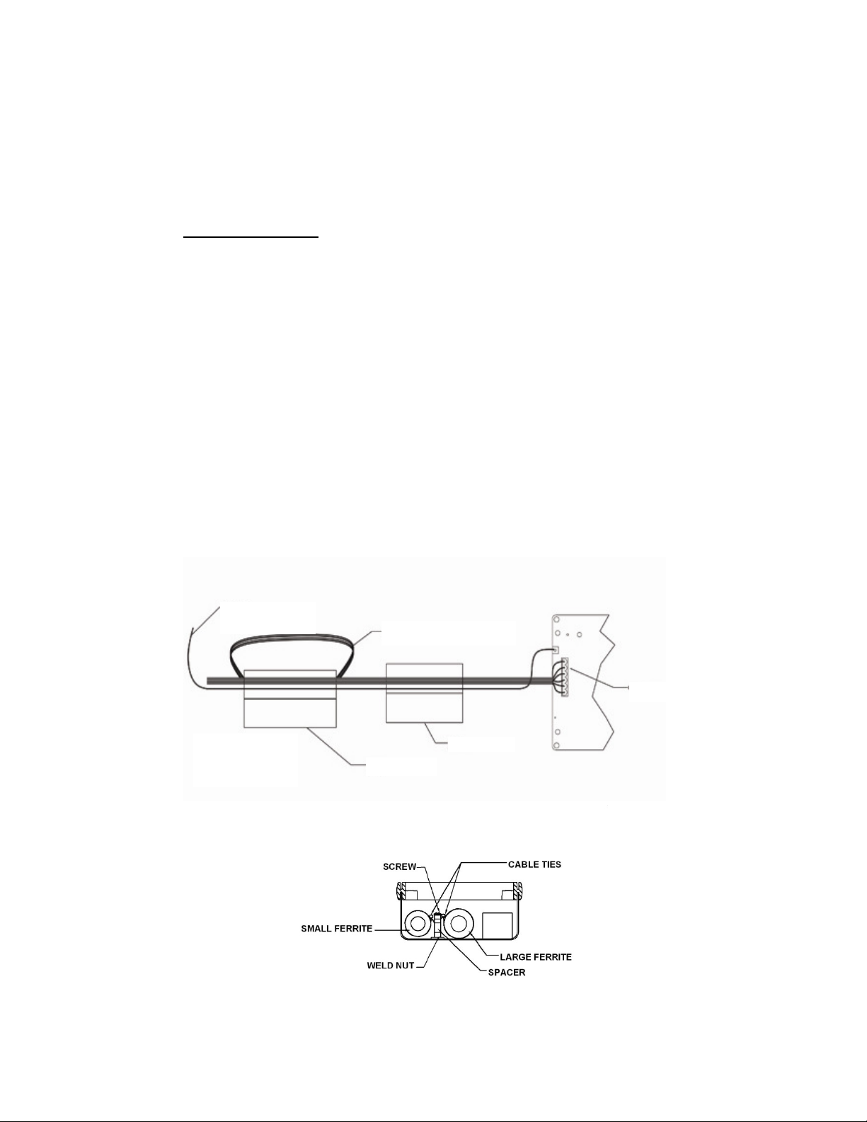
3.4. Ferrite Installation
The Wahl DST600 CE compliance requires installation of 2 clamp-on
ferrites around the internal wiring. These are normally installed when the
system is delivered, however on units with extremely long probes or when
meters are shipped without a probe, these may need to be installed by the
end-user.
There is 1 large ferrite and 1 small ferrite that are required to comply with
the CE directive. See Fig. 2 for reference. The wires coming from the
probe should be passed through the large ferrite, looped around once and
passed through again. Also, route the green/yellow PCB ground lead
through the ferrite once, with the Faston connector toward the probe end
of the ferrite. The large ferrite can then be snapped closed, making sure
that the wires are not pinched. The small ferrite is then installed on the
remaining length of all wires, toward the connector with it passing through
the ferrite only once. The wire does not have to loop through the small
ferrite. The small ferrite can then be snapped closed, making sure that the
wires are not pinched. Cable clamps can then be installed as shown (Fig.
3) to secure the ferrites in place.
Ground Wire Not
Looped
Probe Wire Loop 1 Time
Note:
Ferrites Shown
Open
Large Ferrite
Small Ferrite
Connector P1
Fig. 2
Fig. 3
5 of 16
Page 6

DST600 • DST610 • DST620 Series USER MANUAL
3.5. Grounding
3.5.1. The DST600 should be grounded for CE compliance and optimum
noise immunity.
3.5.2. Grounding on DST600’s with rigid probes is accomplished by
grounding the probe shank. Typically, the equipment that the probe
shank is installed in will be grounded, which will also ground the
DST600 meter assembly.
3.5.3. Grounding on most DST600’s with remote probes is accomplished
in the same manner as the rigid probes. If the remote probe is not
grounded, optional meter mounting bracket, DSA3031, should be
used. This mounting bracket includes a ground lug that allows the
connection of a ground wire for grounding the unit for CE compliance
and optimum noise immunity.
3.5.4. Be certain the PCB ground wire is connected to the housing’s
ground lug, after servicing.
3.6. Ventilation
3.6.1. The DST600 should be installed in an area of adequate air
exchange so that the specified ambient conditions are not exceeded.
3.7. Adjustable Angle Probe – Adjustment
3.7.1. For rotational adjustment, loosen the two long phillips head screws
on the ends of the bracket and rotate the bracket around the coupling
nuts. Tighten screws when position is set to the desired location.
Caution! Do not rotate Digi-Stems with adjustable angles more than
360° in one direction as wire breakage may occur.
3.7.2. Angular adjustment, loosen the two short phillips head screws in
the center slots and pivot the bracket to the desired angle. Tighten
screws.
4. Battery Installation / Replacement / Battery Life
The DST600 uses a single 3.6V C-cell Lithium Thionyl Chloride battery, Wahl
Catalog # DSA3060. The DST600I uses a single 3.6V AA-cell Lithium Thionyl
Chloride battery, Wahl part number 12234-03. Low battery is indicated by “LOW
BATT” displaying in the lower right corner of the display. This indicates
approximately 2-6 weeks of battery life left. Actual time will vary dependent on
Display Update Rate Setting. See section 5.2 for additional information on
update rate and battery life.
4.1. Procedure
4.1.1. For installation or replacement, loosen the four phillips-head screws
in the front cover until the cover is removed. Note: The screws are
held captive by retaining washers and should not be removed
completely.
4.1.2. Remove old battery and dispose of in accordance with local, state
and federal regulations.
6 of 16
Page 7

DST600 • DST610 • DST620 Series USER MANUAL
4.1.3. Insert new battery with polarity as indicated on battery holder.
Positive terminal should be at the top of the PCB.
4.1.4. Replace cover on Digi-Stem enclosure and secure with four screws
tightened to a force of 4 to 5 in-lbs. of torque.
4.2. Battery Life – Battery life is a function of the display update rate and may
be changed to fit the user’s needs. See section 5.3 for details on display
update rate. The following table shows approximate battery life for a
given display update rate.
Display update
rate in seconds
DST600 w/ DSA3060 battery
approximate life in months
DST600I w/ 12234-03 battery
approximate life in months
1 15.7 5.2
2 32.2 10.7
4 60.7 20.2
5 73.8 24.6
10 129.3 43.1
Fig. 4
5. Operation
5.1. Scale Selection °F/°C - Temperature scale is user selectable via jumper
J8 (Fig. 5) on the Printed Circuit Board (PCB). The scale is indicated in
the upper right corner of the display (Fig. 4).
5.2. Resolution Selection – DST600R offers the user the capability of
changing the displayed resolution by selecting either 0.1° or 1° resolution.
Resolution is selectable via jumper J7 (fig. 5) on the PCB, located to the
left of the F/C selection jumper. Selecting 1° will display the truncated
value, so a temperature of 255.9°F would display as 255°F. NOTE: If
using this feature, it is advised to set the meter to 0.1° resolution for doing
calibration measurements, as using 1° can add up to 0.9° of error to the
displayed reading.
5.3. Making measurements and display update rate - With the batteries
installed and probe connected the meter automatically updates the
display with the most recent measurement. Factory default for display
update rate is once every 2 seconds. Display update rate is settable from
.25 seconds to 10 seconds in .25 second increments, using optional
DSTPROG or DSTCAL software.
7 of 16
Page 8

DST600 • DST610 • DST620 Series USER MANUAL
Pin 1
Exc-
RTD
-
J1
5.4. Error Codes - During normal operation, the DST600 continually performs
diagnostic testing on the sensor lines. Errors are indicated by the
following error codes:
Error Code Description
HI Reading is above meters usable range
LO Reading is below meters usable range or sensor is shorted
CbL1 Indicates cable 1 is open (J1 pin 1)
CbL2 Indicates cable 2 is open (J1 pin 2)
CbL3 Indicates cable 3 is open (J1 pin 3)
CbL4 Indicates cable 4 is open (J1 pin 4), or open sensor
err Indicates accuracy error detected. Will also display during rapid
changes of temperature to the RTD sensor.
Prb Indicates probe ID does not match probe ID programmed in meter
- - - Indicates Low Battery Shutdown Mode
Battery Positive
Terminal
1°/0.1°Jumper
J7 DST600R
Only
°F/°C Jumper
J8
Calibration
Port
Ground Wire
PCB
Probe ID
Signal
Probe ID
Ground
RTD +.
Exc+
Fig. 5 (DST600R Shown)
8 of 16
Page 9

DST600 • DST610 • DST620 Series USER MANUAL
6. Calibration
As with all electronic RTD thermometers, there are two main components to the
system. The first component is the electronics, which measures the resistance of
the sensing element and then converts this resistance value to a temperature
indication. The second component is the probe, also referred to as the sensor.
The probes sensor resistance changes as its temperature changes. This change
is in conformance to the DIN EN 60751 Class A standard. As in all manufactured
goods, there are slight variations in the finished parts. A key variable of an RTD
sensor is its resistance at 0°C, referred to as “R0” value. Once this value is
measured, it may be programmed into the meter to correct the temperature
conversion algorithm. Programming and/or calibration require the use of the
DSTPROG or DSTCAL software package. These packages include the USB
cable, USB/DST Interface Box and DST calibration cable. DSTPROG
programming software includes the ability to set the Sample Rate, R0 and
associate a new probe with the meter. DSTCAL includes the DSTPROG
capability plus calibration of the meter and/or calibration of the system (probe
with meter). The DST600 uses the following techniques for calibration. For
details of the calibration, see the DSTCAL software manual.
6.1. Ohm Meter calibration – Ohm Meter calibration is a 2-point calibration,
which calibrates the DST600’s electronics. It requires a NIST traceable
precision resistance source with a known accuracy of ± 0.03 ohms at 90
and 194.1 ohms. Resistors used should have a temperature coefficient
of <5.0-ppm.
6.2. Probe (system) calibration - Probe calibration is a single point calibration
that is performed by placing the probe into an ice bath and following the
on screen prompts of the DSTCAL software. The DST600 and software
will measure the probes R0 value and program it into the DST600’s
memory. The system is then calibrated. After system calibration is
completed, the calibration should be checked at the temperatures of
interest to the end user, using calibrated measuring equipment and
calibration baths. If traceability to a National Standard, such as NIST is
required, this check should be performed using traceable instruments,
performed and documented in compliance to documented procedures.
9 of 16
Page 10

DST600 • DST610 • DST620 Series USER MANUAL
7. Specifications – DST600
10 of 16
Page 11

DST600 • DST610 • DST620 Series USER MANUAL
8. DST610, DST611, DST620 and DST621
Models DST610, DST611, DST620 and DST621 are variations of the DST600
that include an isolated secondary sensor housed in the same probe shank. This
enables the user to have an independent signal from the same probe for use by
a controller or recorder.
8.1. DST610 – Consists of DST600 meter with an isolated secondary sensor
and terminal block. The DST610 provides an isolated secondary RTD for
independent external use allowing the user to have an additional
measuring circuit located in the same probe shank. This reduces the
number of penetrations made into the process and reduces error due to
non-uniformity of the process.
8.1.1. Connection is made via a 4-circuit terminal strip (see Fig. 4). A ½”
NPT female fitting on the side of the enclosure allows access to
connections. This connection should be sealed to prevent moisture,
water or dust entry. We recommend using a liquid-tight conduit fitting
or cable gland for wire entry. User may use in a 2, 3 or 4 wire
configuration as shown in Figure A1.
8.1.2. Secondary RTD specifications are as follows:
R0 100 ohms per DIN EN 60751
Accuracy Class A per DIN EN 60751
Temperature coefficient TCR = 3850 ppm/K
Connection Factory wired for 4-wire, user selectable 2,
3, or 4-wire connection
Self-heating 0.4 K/mW at 0°C
Measuring current 0.3 to 1.0 mA, self-heating must be
considered
Terminal Block type Euro style
Maximum wire size 10 AWG
Fig. 6 – DST610 Terminal Block Wiring
11 of 16
Page 12

DST600 • DST610 • DST620 Series USER MANUAL
8.2. DST611 - All the features of the DST610, and includes a pre-wired Turck
4-pin connector mounted in the side enclosure fitting. This allows
convenient user connection/disconnection. This option requires the use
of a connecting cable or connector (ordered separately). Connector
wiring are shown in Figure A2.
8.2.1. Optional IP68 rated field wireable connectors and cables:
Wahl P/N Description
12075-07 Straight field wireable connector, 4-6 mm cable gland
12075-08 Straight field wireable connector, 6-8 mm cable gland
12075-09 Right angle field wireable connector, 4-6 mm cable gland
12075-10 Right angle field wireable connector, 6-8 mm cable gland
Cable assemblies are single-ended and feature a molded IP68 rated
connector. Opposite end is left un-stripped. Insulation is PVC and rated
to 105°C.
Wahl P/N Description
12361-xxx xxx denotes length in meters, i.e. 12361-010 is 10-meter
cable, 12361-120 is 120-meter length.
Connections for 12361 cable for DST611 are as follows:
Wire Color Connection Signal
Brown Pin 1 Excite +
White Pin 2 RTD +
Blue Pin 3 RTD -
Black Pin 4 Excite -
Non-insulated Coupling nut Shield*
*Shield lead should not be terminated if either meter housing or
probe shank is grounded, to avoid ground loops.
Fig. 7 – DST611 connector wiring
12 of 16
Page 13

DST600 • DST610 • DST620 Series USER MANUAL
Fig. 8 –
DST620
transmitter connection
8.3. DST620 – Consists of DST600 meter with an isolated secondary sensor
and 4-20 mA programmable transmitter. Transmitters are programmed at
the factory. The DST620 provides an isolated current output from the
same probe shank. This reduces the number of penetrations made into
the process and reduces error due to non-uniformity of the process.
8.3.1. Connection is made by hardwiring to the transmitter power supply
terminals as shown in Figure A3. A ½” NPT female fitting on the side
of the enclosure allows access to connections. This connection
should be sealed to prevent moisture, water or dust entry. We
recommend using a liquid-tight conduit fitting or cable gland for wire
entry.
8.3.2. Secondary RTD/transmitter specifications are as follows:
R0 100 ohms per DIN EN 60751
Accuracy Class A per DIN EN 60751
Temperature coefficient TCR = 3850 ppm/K
Connection 4-wire
Programming PC programming (optional cable required)
Power Supply Req. 10 to 35 VDC
Range
Accuracy
-58°F to 500°F (-50 to 260°C)
Greater of ±0.4°F or .1% ± (0.2°C or .1%)
Fault monitoring Programmable Hi (>21.6 mA) or Low (<3.5 mA)
Programming
Port
OR
RTD Input
8.4. DST621 - All the features of the DST620, and includes a Turck 4-pin
connector mounted in the side enclosure fitting that is pre-wired to the
transmitter. This allows convenient user connection/disconnection. This
option requires the use of a connecting cable or connector (ordered
separately). Connector wiring and cable wiring are shown in Figure A4.
See below for connectors and cables:
13 of 16
I OUT -
I OUT +
Page 14

DST600 • DST610 • DST620 Series USER MANUAL
Figure 9
– DST621
8.4.1. Optional IP68 rated field wireable connectors and cables:
Wahl P/N Description
12075-07 straight field wireable connector, 4-6 mm cable gland
12075-08 straight field wireable connector, 6-8 mm cable gland
12075-09 right angle field wireable connector, 4-6 mm cable gland
12075-10 right angle field wireable connector, 6-8 mm cable gland
Cable assemblies are single-ended and feature a molded IP68 rated
connector. Opposite end is left un-stripped. Insulation is PVC and rated
to 105°C.
Wahl P/N Description
12361-xxx xxx denotes length in meters, i.e. 12361-010 is 10-meter
cable, 12361-120 is 120-meter length.
Connections for 12361 cable for DST621 are as follows:
Wire Color Connection Signal
Brown Pin 1 Current out + (+Vdc)
White Pin 2 Current out – (-Vdc)
Blue Pin 3 N/C
Black Pin 4 N/C
Non-insulated Coupling nut Shield*
*Shield lead should not be terminated if meter housing or probe shank is
grounded, to avoid ground loops.
14 of 16
Page 15

DST600 • DST610 • DST620 Series USER MANUAL
9. Specifications – DST610, DST611, DST620, DST621
15 of 16
Page 16

DST600 • DST610 • DST620 Series USER MANUAL
234 Old Weaverville Road, Asheville, NC 28804
10. Service
For calibration, service or technical support, contact:
Wahl Instruments, Inc.
234 Old Weaverville Road
Asheville, NC 28804
Ph.: 800-421-2853 (US only)
828.658.3131
Fax: 828.658.0728
Web: www.palmerwahl.com
800-421-2853 • 828-658-3131 • 828-658-0728
www.palmerwahl.com
info@palmerwahl.com
16 of 16
 Loading...