

Page 1
Intrinsically Safe
- S
écurité Intrinsèqu
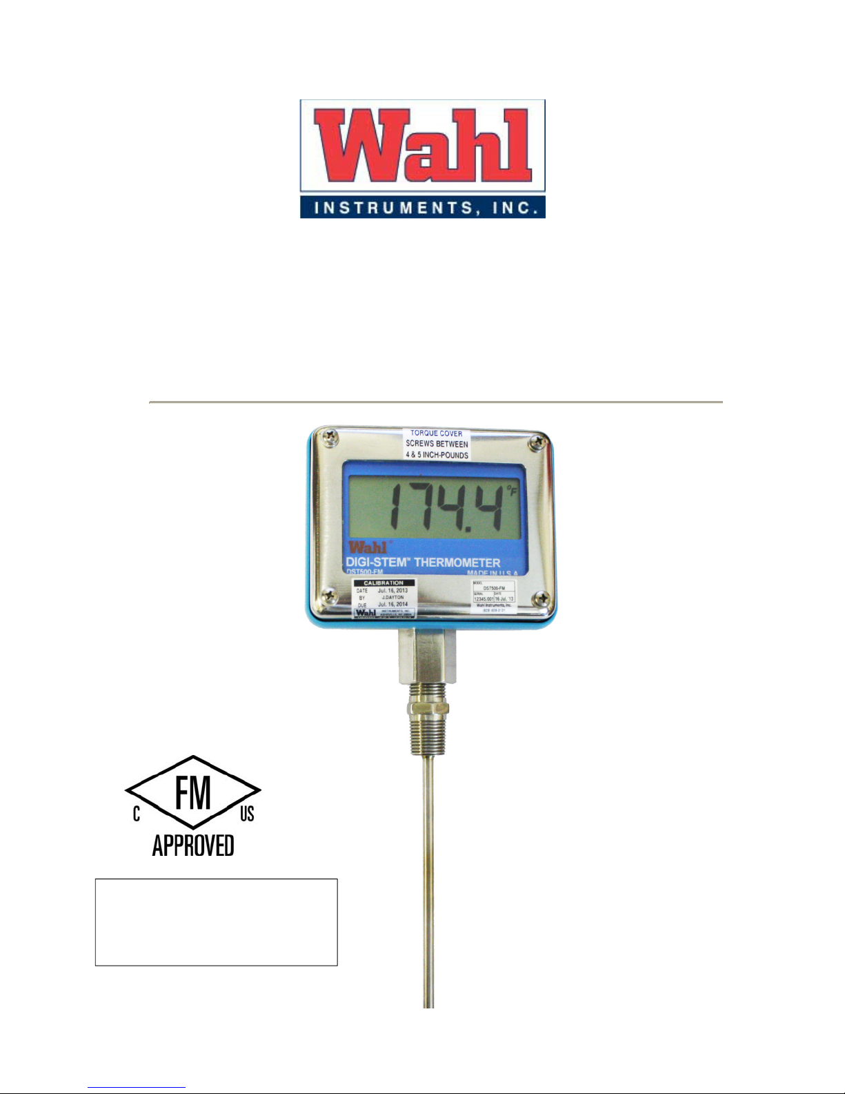
DST500-FM
Digi-Stem
Thermometer
User Manual
IS/CL I, II, III / DIV 1 / GP ABCDEFG;
T4A Ta=70°C; Type 4X
CL I, II, III / DIV 2 / GP ABCDEFG;
T4A Ta=70°C; Type 4X
Do not revise without prior FM approval
WD1094 Rev A
01/31/14
e
Wahl Instruments, Inc.
234 Old Weaverville Road
Asheville, NC 28804
Toll Free 800-421-2853
Phone 828-658-3131
Fax 828-658-0728
www.palmerwahl.com
Page 2

DST500-FM USER MANUAL
WARRANTY & CALIBRATION
Index
1 Introduction________________________________________________________ 3
2 Application and Key Features _________________________________________ 3
3 Factory Mutual Approval _____________________________________________ 3
4 Installation ________________________________________________________ 5
5 Battery Installation/Replacement _______________________________________ 7
6 Operation _________________________________________________________ 8
7 Calibration ________________________________________________________ 9
8 Installation Control Drawing _________________________________________ 11
9 Specifications _____________________________________________________ 12
10 Service ___________________________________________________________ 12
Registration is fast and easy. In about a minute you
can have your product automatically registered for
Warranty Protection and our Calibration Reminder
service. Let Palmer Wahl help you protect your
investment, and maintain product accuracy and
compliance with ISO and other quality standards.
Questions? Call Customer Service
at 1-800-421-2853 or 828-658-3131
Or email: register@palmerwahl.com
REGISTRATION at
www.palmerwahl.com/register
2 of 12
Page 3

DST500-FM USER MANUAL
1 Introduction
The following symbols are used in this manual.
Please adhere to all ! Warnings and Cautions! in this manual.
! Warning – identifies conditions and actions that may be dangerous to the
user.
Caution! – identifies conditions and actions that may cause damage to the
product or equipment.
Note: - provides additional explanatory information.
2 Application and Key Features
The Wahl DST500-FM is designed for temperature monitoring applications in
Classified Hazardous Locations, where a high degree of accuracy and ease of
use are desired. To achieve this objective the DST500-FM incorporates the
following features:
• High reliability, 4-wire, 100 ohm, .00385Ω/Ω/°C, thin-film platinum RTD
sensor per DIN EN 60751, Class A.
• Hazardous Location approval by FM Approvals as defined in Section 3 of this
manual.
• High accuracy 24-bit Delta-Sigma Analog/Digital Converter.
• Probe Error checking: Checks for open wire, open sensor, shorted sensor,
incorrect wiring.
• Programmable RØ: Allows programming of the sensing probes specific RØ
value into the meter for accurate temperature calibration.
3 Factory Mutual Approval
3.1 The DST500-FM when used with the Wahl p/n DSA3060 battery(Tadiran
model TL-2200), carries hazardous location approval and is suitable for use
in the following locations.
• Intrinsically Safe; Class I, II and III; Division 1; Groups ABCDEFG;
Temperature Class T4A Ta = 70°C; Indoor and Outdoor (Type 4X)
Hazardous Locations.
• Class I, II, III; Division 2; Groups ABCDEFG; Temperature Class T4A Ta =
70°C; Indoor and Outdoor (Type 4X) Hazardous Locations
• All Non-hazardous Locations
3 of 12
Page 4

DST500-FM USER MANUAL
3.2 ! English Warnings
! Warning – Please adhere to the following warnings:
! Warning - Battery MUST be changed in an Unclassified Location
only.
! Warning – Electrostatic Charging Hazard
The DST500-FM enclosure includes 2 non-metallic components,
consisting of the polycarbonate window and the blue colored
polycarbonate H-frame, which thereby increase the risk of electrostatic
charge buildup. The following precautions may be used to reduce the risk
of static discharge.
• Do not contact the viewing window or the blue H-frame when a
flammable or combustible atmosphere is present.
• Coat the window and H-frame using a topical anti-static coating
such as Desco Industries part number 10415 or equivalent, recoating as needed.
• Do not use in the presence of high electro-magnetic fields.
• Clean only with damp cloth using clean water.
• Ensure either the enclosure or the probe is grounded to building or
earth ground.
! Warning – Substitution of the following components may impair
suitability for Division 2:
• Battery – Wahl P/N DSA3060; Manufacturer – Tadiran, model TL-2200
3.3 ! Avertissements Français
! Avertissement - S'il vous plaît respecter les avertissements suivants:
! Avertissement - La batterie doit être changée en dehors d’une zone
classifiée.
! Avertissement - Risque de charge électrostatique
Le boîtier DST500-FM comprend 2 composants non métalliques en
polycarbonate, la fenêtre et le cadre bleu en forme de H, qui augmentent le
risque d'accumulation de charges électrostatiques. Les précautions suivantes
sont à suivre pour réduire le risque de décharge électrostatique.
• Ne pas toucher la fenêtre de visualisation ou le cadre bleu en forme de H
en présence d'une atmosphère inflammable ou combustible.
• recouvrir la fenêtre et le cadre en utilisant un revêtement antistatique tel
que du Desco Industrie référence 10415 ou équivalent, recouvrir de nouveau si
besoin.
• Ne pas utiliser en présence de forts champs électromagnétiques.
4 of 12
Page 5

DST500-FM USER MANUAL
• Nettoyer uniquement avec un chiffon humide et de l'eau propre.
S'assurer que le boitier ou la sonde sont mis à la terre.
! Avertissement - Le remplacement des composants suivants peut
altérer l'aptitude à la Division 2:
Batterie - Référence Wahl DSA3060, Fabricant - Tadiran, modèle TL-2200
4
Installation
Caution! Installation should be in accordance with Wahl Control Drawing 13327.
Caution! See important information regarding Lithium Batteries found in Wahl
document #WD1053, before proceeding!
Y
our unit was shipped partially assembled. Installation of the battery by the enduser is necessary as transportation regulations prohibit shipping units with the
battery installed. Units with long probes may be shipped unassembled. After
installation of the battery, verify the display is operational and remove the
protective film from the window. In the event the display is not operational, check
that the battery is installed properly by following the battery installation
procedure, section 5 of this manual.
4.1 Meter Mounting
Fixed probes may be mounted by the threaded fitting or sanitary clamp into
the process. Apply thread sealing compound or Teflon tape to the threaded
fitting as required. Units with a swivel nut fitting may be adjusted during
installation for best viewing angle.
Caution! Do not use the Digi-Stem enclosure to tighten meter. Use a wrench
on the coupling nut for tightening.
4.2 Wire Connections –The following is for installation of fixed probe.
4.2.1 Loosen the four Phillips head screws in the front cover until the cover is
removed. Note: The screws are held captive by retaining washers and
should not be removed completely.
4.2.2 Remove the 4-pin pluggable terminal-strip connector (P1) from the PCB
mating connector J1 and connect probe wires as shown in the table below
and in Fig. 4 and following the ferrite installation as defined in paragraph
4.3.
P1/J1 – DST500-FM Probe Wiring
Pin # Label Fixed Probe
1 + EXCIT WHITE
2 + RTD / TC WHITE
3 - RTD / TC BLACK
4 - EXCIT BLACK
5 of 12
Page 6

DST500-FM USER MANUAL
4.2.3 Connect pluggable terminal strip to PCB connector P1.
4.2.4 Install battery with polarity as indicated on battery holder.
4.2.5 Replace cover on Digi-Stem enclosure and secure with four screws
tightened to a force of 4 to 5 in-lbs. of torque.
4.3 Ferrite Installation
The Wahl DST500-FM requires installation of 2 ferrites, installed on the
internal wiring. This is normally installed when the system is delivered,
however on units with extremely long probes these may need to be
installed by the end-user during the installation process.
To install the ferrites, (reference Fig 2) first, mount the large ferrite as shown.
Clamp the small ferrite around the 4 probe wires and the green/yellow ground
wire as close to the ground wire spade terminal as possible. Make certain not to
pinch the probe wires in the ferrite. Route the 4 probe wires through the solid
ferrite and loop back around through the ferrite 2 more times for a total of 3
passes through the ferrite. Connect wires to PCB plug P1 per probe wiring table.
Fig. 2
4.4 Grounding
4.4.1 The DST500-FM should be grounded for optimum noise immunity. Install
in compliance to Wahl Control Drawing 13327.
4.4.2 Grounding on DST500-FM’s with rigid probes is accomplished by
grounding the probe shank. Typically, the equipment that the probe shank
is installed in will be grounded, which will also ground the DST500 meter
assembly.
4.4.3 After servicing, be certain the Printed Circuit Board’s ground wire is
connected to the housing’s ground lug.
6 of 12
Page 7

DST500-FM USER MANUAL
Battery Life Table
4.4.4 If you have questions about grounding of the DST500-FM please contact
Wahl Instruments Customer Service as listed in section 9 of this manual.
4.5 Ventilation
4.5.1 The DST500-FM should be installed in an area of adequate air exchange
so that the specified ambient conditions are not exceeded.
5 Battery Installation/Replacement
! WARNING - Battery MUST be changed in the Unclassified Location
only.
The DST500-FM uses a single 3.6V Lithium Thionyl Chloride battery, Wahl P/N
DSA3060, (Tadiran TL-2200). Use of this battery is required for use in
hazardous locations as specified in section 3.1.
Lo battery is indicated by “LOW BATT” displaying in the lower right corner of the
display (Fig. 3). This indicates approximately 1-2 weeks of battery life left. The
battery should be replaced at this time. As the battery continues to drain “- - - - “will appear, indicating the battery is too low for an accurate measurement. The
battery must be replaced at this time. Battery life will vary dependent on Display
Update Rate Setting as shown in the Battery Life Table below.
5.1 For installation or replacement, loosen the four Phillips-head screws in the
front cover until the cover is removed. Note: The screws are held captive
by retaining washers and should not be removed completely.
5.2 Remove old battery and dispose of in accordance with local, state and
federal regulations.
5.3 Insert new battery, Wahl Catalog # DSA3060, with polarity as indicated on
battery holder. Positive terminal should be at the top of the PCB.
5.4 Replace cover on Digi-Stem enclosure and secure with four screws
tightened to a force of 4 to 5 in-lbs. of torque.
7 of 12
Fig. 3
Page 8

DST500-FM USER MANUAL
Pin 1
-
EXCITE
+EXCIT
6 Operation
6.1 Scale Selection °F/°C – Temperature scale is user selectable via jumper J8
(Fig. 4) on the Printed Circuit Board (PCB). The scale is indicated in the
upper right corner of the display (Fig. 3.)
6.2 Making measurements - With the batteries installed and probe connected
the meter automatically updates the display with the most recent
measurement. Factory default for measurement LCD Refresh
(sample/display) rate is set to 8 for a 2 second update.
6.3 Error Codes - During normal operation, the DST500-FM continually
performs diagnostic testing on the sensor lines. Errors are indicated
by the following error codes:
Error Code Description
HI Reading is above meters usable range
LO Reading is below meters usable range or sensor is shorted
CbL1 Indicates cable 1 is open (J1 pin 1)
CbL2 Indicates cable 2 is open (J1 pin 2)
CbL3 Indicates cable 3 is open (J1 pin 3)
CbL4 Indicates cable 4 is open (J1 pin 4), or open sensor
- - - - - Indicates Low Battery Shutdown Mode
°F/°C Jumper
J8
Calibration
Port
Battery Positive
Terminal
-RTD
PCB
Ground Wire
J1/P1
Fig. 4
8 of 12
Page 9

DST500-FM USER MANUAL
7 Calibration
As with all electronic RTD thermometers, there are two main components to the
system. The first component is the electronics, which measures the resistance of
the sensing element and then converts this resistance value to a temperature
indication. The second component is the probe, also referred to as the sensor.
The probes sensor resistance changes as its temperature changes. This change
is in conformance to the DIN EN 60751 Class A standard. As in all manufactured
goods, there are slight variations in the finished parts. A key variable of RTD
sensors is its resistance at 0°C, referred to as “RØ” value. Once this value is
measured, it may be programmed into the meter to correct the temperature
conversion algorithm. Programming and/or calibration require the use of the
DSTCAL software package. This package includes the USB cable, USB/DST
Interface Box and DST calibration cable. DSTCAL programming software
includes the ability to set the Sample Rate, RØ value and allows calibration of the
meter and/or calibration of the system (calibrates meter with probe’s R0 value).
The DST500-FM uses the following methods for calibration. For details of the
calibration, see the DSTCAL software manual, Wahl P/N W1037.
7.1 Ohm Meter calibration – Ohm Meter calibration is a 2-point calibration,
which calibrates the DST500-FM electronics. It requires a NIST traceable
precision resistance source with a known accuracy of ± 0.03 ohms at 50.00
and 280.00 ohms. Resistors used should have a temperature coefficient of
<5.0-ppm.
7.2 Probe (system) calibration - Probe calibration is a single point calibration
which is performed by placing the probe into an ice bath and following the
on screen prompts of the DSTCAL software. The DST500-FM and
software will measure the probes RØ value and program it into the
DST500-FM’s memory. The system is then calibrated. After system
calibration is completed, the calibration should be checked at the
temperatures of interest to the end user, using calibrated accurate
standards and calibration baths.
7.2.1 DST500-FM calibration adjustment - Calibration is accomplished via the
DSTCAL software package and associated hardware interface. Method 1
may also be performed with the DSTPROG software. Optional cable
extensions are available for convenience in calibrating fixed probes.
7.2.2 The two methods of calibrating a meter with probe as a system are:
7.2.3 Method 1
The first method uses an ice bath and high accuracy ohmmeter
along with the DSTCAL software.
For fixed probes:
1) Disconnect the probe from the meter and place the probe in an
ice bath or 0°C circulating bath. Allow stabilization.
9 of 12
Page 10

DST500-FM USER MANUAL
2) Use a high accuracy ohmmeter to measure the probes R0 value.
3) Connect the meter to the PC via the 13506 Interface Module.
4) Enter the probes measured R0 value into the R0 box, under the
Module Calibration Data section. Press “Set” to program the
DST500-FM memory with this value.
NOTE: For this method, with fixed probes, the 13500-04 extension
cable is not required, as the probe is removed from the meter.
7.2.4 Method 2
The second method is to use the DST500-FM meter to acquire the
R0 value. For fixed probes, this method is made easier, by using
the 13500-04 extension cable.
1) For fixed probes, disconnect probe from meter, and install the
13500-04, extension cable between the probe connector and the
meter PCB connector. This allows the meter to be placed on a
bench, rather than dangling above the ice bath. Place the probe in
an ice bath. Allow stabilization.
2) Connect the meter to the PC via the 13506 Interface Module.
3) Select and run the “Probe (system) Calibration” program and
follow the on-screen prompts. A running average of R0 is
displayed in the R0 box. Press “Capture R0” to freeze the reading
then press “Yes” to store the measured value into the DST500-FM
memory.
Note: 1) When using this method, the meter may display erratic
readings during the measurement of the probes resistance. This is
normal and does not affect the calibration.
2) During the acquisition process, the software continues to
take samples after the 10th sample. This running average allows
the user to verify the probes stability. If this reading continues to
drop, then stability has not yet been achieved.
10 of 12
Page 11

DST500-FM USER MANUAL
8 Installation Control Drawing
11 of 12
Page 12

DST500-FM USER MANUAL
234 Old Weaverville Road, Asheville,
NC 28804
9 Specifications
10 Service
For calibration, service or technical support, contact:
Wahl Instruments, Inc.
234 Old Weaverville Road
Asheville, NC 28804
Ph.: 800-421-2853 (US only)
828.658.3131
Fax: 828.658.0728
Web: www.palmerwahl.com
800-421-2853 • 828-658-3131 • 828-658-0728
www.palmerwahl.com
info@palmerwahl.com
12 of 12
 Loading...