

WAGO 750-626/040-000, 750-602/040-000, 750-624/040-001, WAGO-I/O-SYSTEM 750 XTR Series, 750-612/040-000 User Manual
...Page 1
Pos: 2 /Dokumentation allgemein/Einband/Einband Handbuch - Frontseite 20 15 - mit D ocV ari abl en (S ta ndar d) @ 9\mod_1285229289866_0.docx @ 64941 @ @ 1
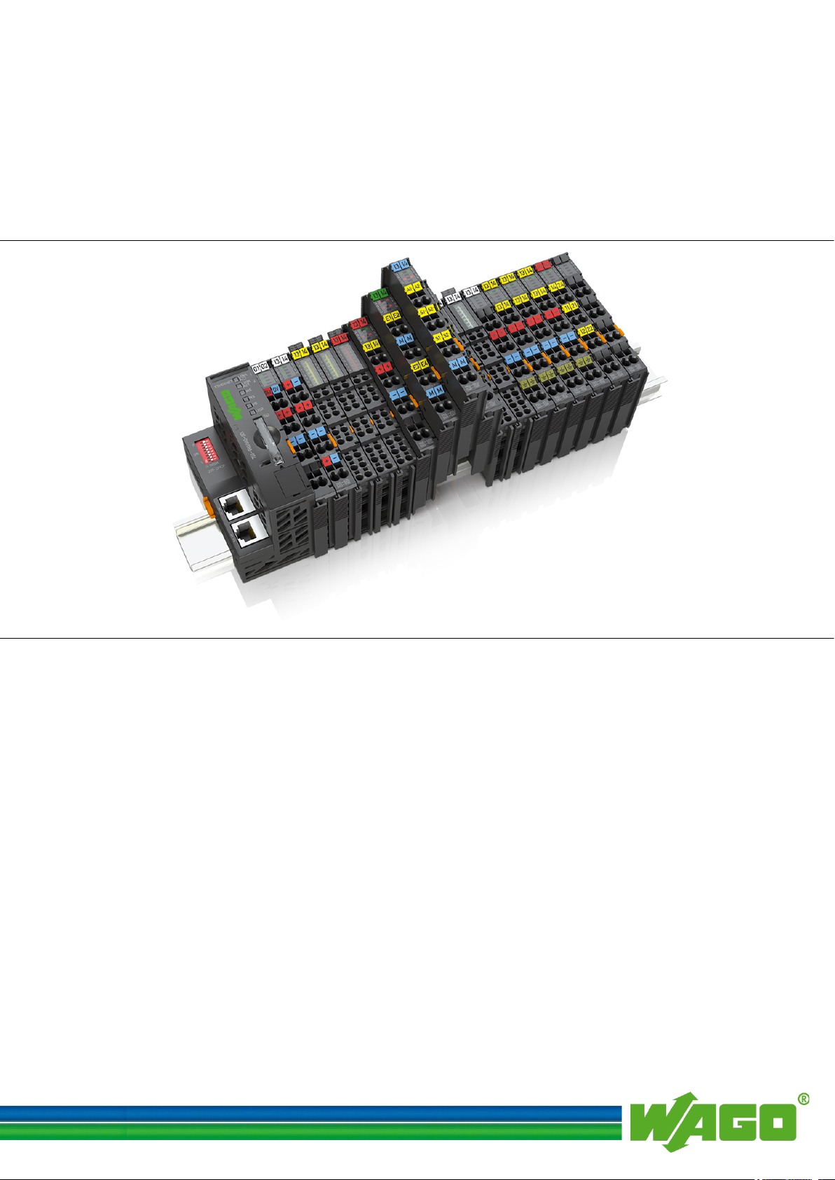
WAGO-I/O-SYSTEM 750 XTR
Manual
750-xxxx/0040-xxxx
Notes /XTR
Guidelines and Recommendations
Version 1.2.0
Pos: 3 /Alle S erie n (Al lge mei ne M odul e) /Rec htli ch es, Allg emei n es/I mpre ssu m f ür St and ard han dbüc h er - al lg. Ang aben, A nschr iften, Telef onnu mmern un d E-Mail -Adr esse n @ 3\mod_1219151118203_21.docx @ 21060 @ @ 1
Design
for Increasing Operational Safety
Page 2

2 WAGO-I/O-SYSTEM 750 XTR
750-xxxx/0040-xxxx Design Notes /XTR
© 2016 by WAGO Kontakttechnik GmbH & Co. KG
All rights reserved.
WAGO Kontakttechnik GmbH & Co. KG
Hansastraße 27
D-32423 Minden
Phone: +49 (0) 571/8 87 – 0
Fax: +49 (0) 571/8 87 – 1 69
E-Mail: info@wago.com
Web: http://www.wago.com
Technical Support
Phone: +49 (0) 571/8 87 – 5 55
Fax: +49 (0) 571/8 87 – 85 55
E-Mail: support@wago.com
Every conceivable measure has been taken to ensure the accuracy and
completeness of this documentation. However, as errors can never be fully
excluded, we always appreciate any information or suggestions for improving the
documentation.
E-Mail: documentation@wago.com
We wish to point out that the software and hardware terms as well as the
trademarks of companies used and/or mentioned in the present manual are
generally protected by trademark or patent.
=== Ende der Li st e für Te xtm arke Ei nba nd_ vorn e ===
Manual
Version 1.2.0
Page 3

WAGO-I/O-SYSTEM 750 XTR Table of Contents 3
750-xxxx/0040-xxxx Design Notes /XTR
Pos: 5 /Do kume ntati on allg em ein /Ver zeic hni sse /Inh alts ver z eich nis - Ü ber schrif t oG und Verzei chnis @ 3\mod_1219151230875_21.docx @ 21063 @ @ 1
Table of Contents
1 Notes about this Documentation ................................................................. 5
1.1 Validity of this Documentation ................................................................. 5
1.2 Copyright ................................................................................................... 5
1.3 Symbols ..................................................................................................... 6
1.4 Number Notation ....................................................................................... 8
1.5 Font Conventions ...................................................................................... 8
2 Important Notes ........................................................................................... 9
2.1 Legal Bases ............................................................................................... 9
2.1.1 Subject to Changes ............................................................................... 9
2.1.2 Personnel Qualifications ....................................................................... 9
2.1.3 Use of the WAGO-I/O-SYSTEM 750 in Compliance with
Underlying Provisions .......................................................................... 9
2.1.4 Technical Condition of Specified Devices ......................................... 10
2.2 Safety Advice (Precautions) .................................................................... 11
3 System Description..................................................................................... 13
3.1 Manufacturing Number ........................................................................... 15
3.2 Component Update .................................................................................. 16
3.3 Storage, Assembly and Transport ........................................................... 16
3.4 Assembly Guidelines/Standards .............................................................. 16
3.5 Technical Data ........................................................................................ 17
3.5.1 Mechanics ........................................................................................... 17
3.5.2 Electrical Safety.................................................................................. 17
3.5.3 Connection Type ................................................................................ 18
3.5.4 Climatic Environmental Conditions ................................................... 18
3.5.5 Residential Use ................................................................................... 19
3.5.6 Example Dimensions .......................................................................... 20
4 Standards and Approvals .......................................................................... 21
5 Assembly ..................................................................................................... 23
5.1 Mounting Position ................................................................................... 23
5.2 Overall Configuration ............................................................................. 23
5.3 Mounting onto Carrier Rail ..................................................................... 24
5.3.1 Carrier Rail Properties ........................................................................ 24
5.3.2 WAGO DIN Rail ................................................................................ 25
5.4 Spacing .................................................................................................... 26
5.5 Mounting Sequence ................................................................................. 27
5.6 Inserting and Removing Devices ............................................................ 29
5.6.1 Inserting the Fieldbus Coupler/Controller .......................................... 29
5.6.2 Removing the Fieldbus Coupler/Controller ....................................... 29
5.6.3 Inserting the I/O Module .................................................................... 30
5.6.4 Removing the I/O Module .................................................................. 31
6 Connect Devices ......................................................................................... 32
6.1 Data Contacts/Internal Bus ..................................................................... 32
6.2 Power Contacts/Field Supply .................................................................. 33
6.3 Connecting a Conductor to the CAGE CLAMP® ................................... 34
Manual
Version 1.2.0
Page 4

4 Table of Contents WAGO-I/O-SYSTEM 750 XTR
750-xxxx/0040-xxxx Design Notes /XTR
6.4 Connecting a Conductor to the Push-in CAGE CLAMP® ...................... 35
6.5 Power Supply .......................................................................................... 36
6.5.1 Isolation .............................................................................................. 36
6.5.2 System Supply .................................................................................... 37
6.5.2.1 Connection ..................................................................................... 37
6.5.2.2 Dimensioning ................................................................................. 38
6.5.3 Field Supply........................................................................................ 41
6.5.3.1 Connection ..................................................................................... 41
6.5.3.2 Fusing ............................................................................................ 42
6.5.4 Power Supply for Mixed Operation ................................................... 44
6.5.5 Supplementary Power Supply Regulations ........................................ 45
6.5.6 Supply Example.................................................................................. 47
6.5.7 Power Supply Units ............................................................................ 49
6.6 Grounding ............................................................................................... 50
6.6.1 Grounding the DIN Rail ..................................................................... 50
6.6.1.1 Framework Assembly .................................................................... 50
6.6.1.2 Insulated Assembly ........................................................................ 50
6.6.2 Grounding Function............................................................................ 51
6.7 Shielding ................................................................................................. 52
6.7.1 General ............................................................................................... 52
6.7.2 Bus Cables .......................................................................................... 52
6.7.3 Signal Lines ........................................................................................ 53
6.7.4 WAGO Shield Connecting System .................................................... 53
List of Figures ...................................................................................................... 54
List of Tables ........................................................................................................ 55
=== Ende der Li st e für Te xtm arke Ver zeic hni s_v or ne == =
Manual
Version 1.2.0
Page 5
WAGO-I/O-SYSTEM 750 XTR Notes about this Documentation 5
750-xxxx/0040-xxxx Design Notes /XTR
Pos: 7 /Alle Ser ie n (All ge mein e M odul e) /Üb ersc hri ften/ Ne ue Ü ber schr ift en/ Ebe ne 1Hin weis e z u di eser D okum ent atio n - Ü ber schri ft 1 @ 4\ mod_1237987661750_21.docx @ 29029 @ 1 @ 1
1 Notes about this Documentation
Pos: 8 /Alle S erie n (Al lge mei ne M odul e) /Sic her hei ts- und sonstige Hinweise/HinweisHinweis: Dokumentation aufbewahren @ 4\mod_1237987339812_21.docx @ 29026 @ @ 1
Always retain this documentation!
This documentation is part of the product. Therefore, retain the documentation
during the entire service life of the product. Pass on the documentation to any
subsequent user. In addition, ensure that any supplement to this documentation is
included, if necessary.
Pos: 9 /Alle S erie n (Al lge mei ne M odul e) /Üb ersc hri ften/ Ne ue Ü ber sc hrift en /Ebe ne 2Gül tig keit sber eic h - Ü ber schr if t 2 @ 12\ mod_1338912448776_21.docx @ 96469 @ 2 @ 1
1.1 Validity of this Documentation
Pos: 10 /Ser ie 75 0 (WA GO-I/ O-SYS TEM )/H in weis e z ur D okum ent ati on/ Gül tigk eits ber eic h/G ültig k eits ber eich Dok um enta tio n S yste mbesc hr eibu ng 750- xxxx @ 1 4\mod_1358944040650_21.docx @ 109374 @ @ 1
This documentation is only applicable to the WAGO-I/O-SYSTEM 750
XTRseries.
Pos: 11 /Ser ie 75 0 (WA GO-I/ O-SYS TEM )/H in weis e z ur D okum ent ati on/Hi n weis e/Ac ht ung : Hin wei s z ur S yst embes chr ei bung 7 50-xxxx/ 040-000 @ 27\mod_1468507202467_21.docx @ 216916 @ @ 1
The WAGO-I/O-SYSTEM 750 XTR shall only be installed and operated
according to the instructions in this system description and the manuals for the
used fieldbus coupler/controller and I/O modules.
Consider power layout of the WAGO-I/O-SYSTEM 750 XTR!
In addition to these operating instructions, you will also need the manual for the
used fieldbus coupler/controller and I/O modules, which can be downloaded at
www.wago.com. There, you can obtain important information including
information on electrical isolation, system power and supply specifications.
Pos: 12.1 /Al l e Ser ien ( Al lge mei ne M od ule)/Ü ber sc hrift e n/Eb ene 2/Ur h ebers chut z - Ü ber schr ift 2 @ 2 3\mod_1435647042188_21.docx @ 184808 @ 2 @ 1
1.2 Copyright
Pos: 12.2 /Alle S eri en ( Allg emei ne Mo dule) /R echt lich es , Allg em ei nes/ Urh eber sc hutz aus führ lic h @ 4\mod_1235565145234_21.docx @ 27691 @ @ 1
This Manual, including all figures and illustrations, is copyright-protected. Any
further use of this Manual by third parties that violate pertinent copyright
provisions is prohibited. Reproduction, translation, electronic and phototechnical
filing/archiving (e.g., photocopying) as well as any amendments require the
written consent of WAGO Kontakttechnik GmbH & Co. KG, Minden, Germany.
Non-observance will involve the right to assert damage claims.
Pos: 12.3 /Dokumentation allgemein/Gliederungselemente/---Seitenwechsel--- @ 3\mod_1221108045078_0.docx @ 21810 @ @ 1
Manual
Version 1.2.0
Page 6
6 Notes about this Documentation WAGO-I/O-SYSTEM 750 XTR
750-xxxx/0040-xxxx Design Notes /XTR
Pos: 12.4 /Al l e Ser ien ( Al lge mei ne M od ule)/Ü ber sc hrift e n/N eue Ü ber schr if ten/ Ebe ne 2 Sy mbol e - Ü bersc hri ft 2 @ 13\ mod_1351068042408_21.docx @ 105270 @ 2 @ 1
1.3 Symbols
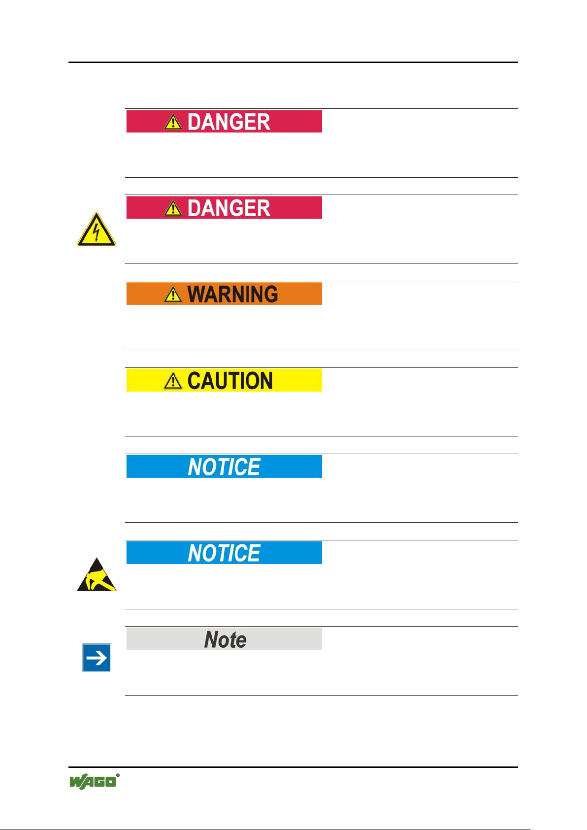
Pos: 12.5.1 /All e Serie n (All gemei ne Mod ule)/ Sicher heits- und sons ti ge Hi n weis e/Ge fahr /G efa hr: _War nu ng vor P ers onen sch äde n al lge mei n_ - Erläu terung @ 13\mod_1343309450020_21.docx @ 101029 @ @ 1
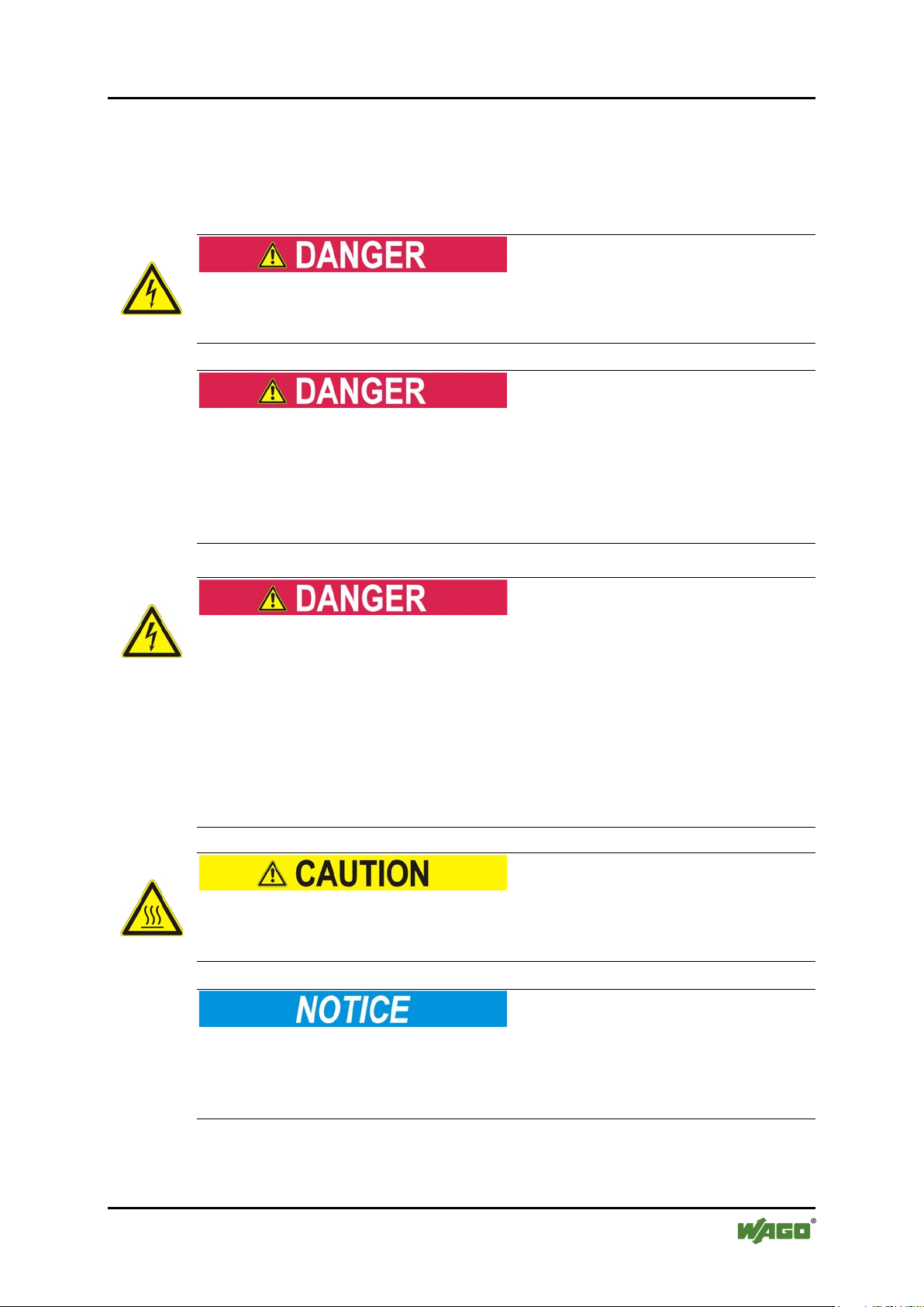
Personal Injury!
Indicates a high-risk, imminently hazardous situation which, if not avoided, will
result in death or serious injury.
Pos: 12.5.2 /All e Serie n (All gemei ne Mod ule)/ Sicher heits- und sonsti ge Hin weise/ Gefahr /Gef ahr: _ Warnu ng vor Per sonen schä den dur ch ele ktrisc hen Stro m_ - Erläuterung @ 13\mod_1343309694914_21.docx @ 101030 @ @ 1
Personal Injury Caused by Electric Current!
Indicates a high-risk, imminently hazardous situation which, if not avoided, will
result in death or serious injury.
Pos: 12.5.3 /All e Serie n (All gemei ne Mod ule)/ Sicher heits- und sons ti ge Hi n weis e/W arn ung/ War nung : _ Warn ung vor Perso nensc häde n allgem ein_ - Erläuterung @ 13\mod_1343309877041_21.docx @ 101035 @ @ 1
Personal Injury!
Indicates a moderate-risk, potentially hazardous situation which, if not avoided,
could result in death or serious injury.
Pos: 12.5.4 /All e Serie n (All gemei ne Mod ule)/ Sicher heits- und sonsti ge Hin weise/ Vorsic ht/V orsich t: _War nung v or Pers onens chäd en allge mein _ - Erläuterung @ 13\mod_1343310028762_21.docx @ 101038 @ @ 1
Personal Injury!
Indicates a low-risk, potentially hazardous situation which, if not avoided, may
result in minor or moderate injury.
Pos: 12.5.5 /All e Serie n (All gemei ne Mod ule)/ Sicher heits- und sons ti ge Hi n weis e/Ac htu ng/ Ach tung : _ War nung vor Sac hsc häd en al lg emei n_ - Erläuterung @ 13\mod_1343310134623_21.docx @ 101041 @ @ 1
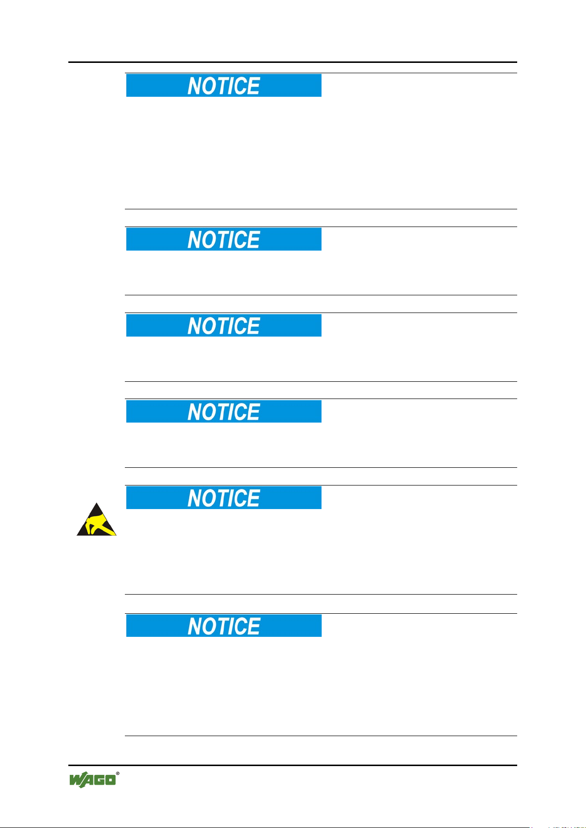
Damage to Property!
Indicates a potentially hazardous situation which, if not avoided, may result in
damage to property.
Pos: 12.5.6 /All e Serie n ( All ge meine Mo dul e)/ Sich erh eits- und sonsti ge Hin weise/ Achtu ng/Ac htung : _War nung vor Sachsc häden durc h elektr ostatis che Au fladu ng_ - Erl äuter ung @ 13\ mod_1343310227702_21.docx @ 101044 @ @ 1
Damage to Property Caused by Electrostatic Discharge (ESD)!
Indicates a potentially hazardous situation which, if not avoided, may result in
damage to property.
Pos: 12.5.7 /All e Serie n (All gemei ne Mod ule)/ Sicher heits- und sonstige Hinweise/Hinweis/Hinweis: _Wichtiger Hinweis allgemein_ - Erläut eru ng @ 13\mod_1343310326906_21.docx @ 101047 @ @ 1
Important Note!
Indicates a potential malfunction which, if not avoided, however, will not result in
damage to property.
Pos: 12.5.8 /All e Serie n (All gemei ne Mod ule)/ Sicher heits- und sons ti ge Hi n weis e/Inf or mati on/I nf orma tio n: _ Wei ter e Inf or mati on allg emei n_ - Erl äuter ung @ 13 \mod_1343310439814_21.docx @ 101051 @ @ 1
Manual
Version 1.2.0
Page 7

WAGO-I/O-SYSTEM 750 XTR Notes about this Documentation 7
750-xxxx/0040-xxxx Design Notes /XTR
Additional Information:
Refers to additional information which is not an integral part of this
documentation (e.g., the Internet).
Pos: 12.6 /Dokumentation allgemein/Gliederungselemente/---Seitenwechsel--- @ 3\mod_1221108045078_0.docx @ 21810 @ @ 1
Manual
Version 1.2.0
Page 8
8 Notes about this Documentation WAGO-I/O-SYSTEM 750 XTR
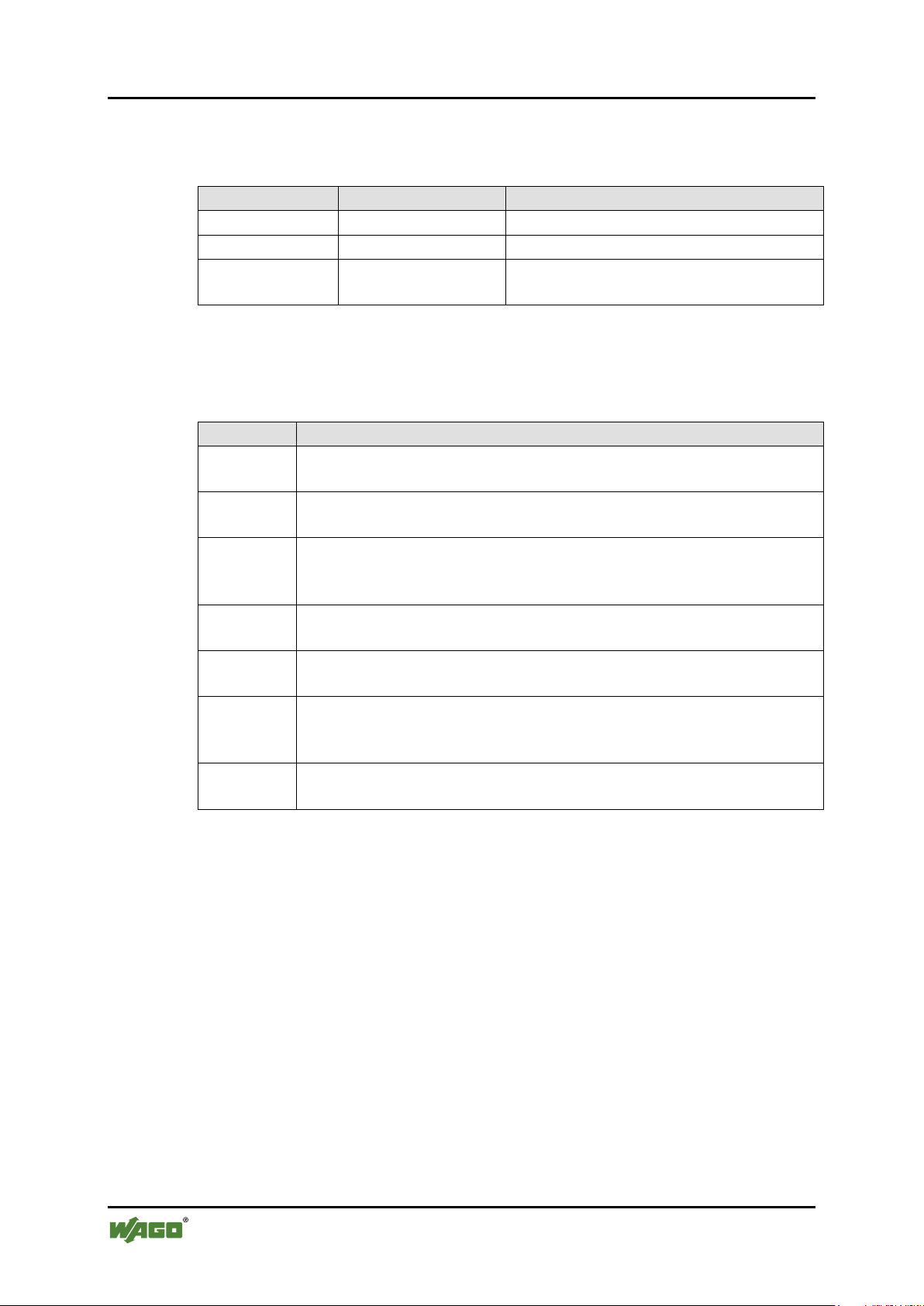
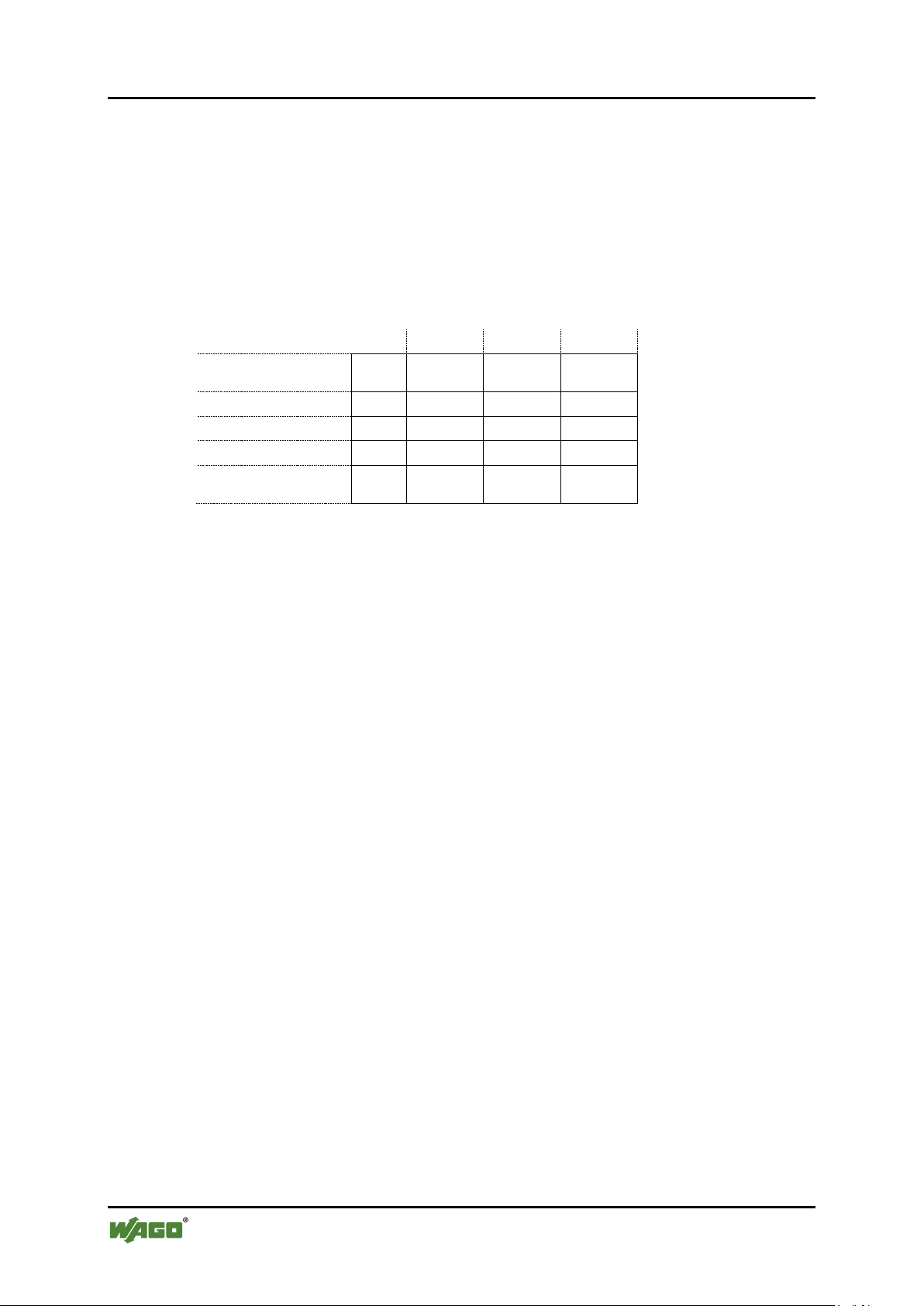
Table 1: Number Notation
Number Code
Example
Note
Decimal
100
Normal notation
Hexadecimal
0x64
C notation
Binary
'100'
'0110.0100'
In quotation marks, nibble separated with
dots (.)
Table 2: Font Conventions
Font Type
Indicates
italic
Names of paths and data files are marked in italic-type.
e.g.: C:\Program Files\WAGO Software
Menu
Menu items are marked in bold letters.
e.g.: Save
>
A greater-than sign between two names means the selection of a
e.g.: File > New
Input
Designation of input or optional fields are marked in bold letters,
e.g.: Start of measurement range
“Value”
Input or selective values are marked in inverted commas.
e.g.: Enter the value “4 mA” under Start of measurement range.
[Button]
Pushbuttons in dialog boxes are marked with bold letters in square
e.g.: [Input]
[Key]
Keys are marked with bold letters in square brackets.
e.g.: [F5]
750-xxxx/0040-xxxx Design Notes /XTR
Pos: 12.7 /Al l e Ser ien ( Al lge mei ne M od ule)/Ü ber sc hrift e n/Eb ene 2/D arst ell ung der Z a hle nsys tem e - Ü bers chri ft 2 @ 23\mod_1435647128078_21.docx @ 184811 @ 2 @ 1
1.4 Number Notation
Pos: 12.8 /Al l e Ser ien ( Al lge mei ne M od ule)/R ec htli ches , Al lg emei nes /Za hle nsy st eme @ 3\mod_1221059454015_21.docx @ 21711 @ @ 1
Pos: 12.9 /Al l e Ser ien ( Al lge mei ne M od ule)/Ü ber sc hrift e n/Eb ene 2/Sc hr ift kon venti one n - Ü bersc hr ift 2 @ 23\ mod_1435647186005_21.docx @ 184814 @ 2 @ 1
1.5 Font Conventions
Pos: 12.10 / All e S erie n (Al lge mei ne M o dule) /Re cht lich es, All ge mein es/ Schr ift kon venti on en @ 3\mod_1221059521437_21.docx @ 21714 @ @ 1
Pos: 13 /Dokum entati on allg emei n/Gli ederung sele mente /---Seit enwe chs el--- @ 3\mod_1221108045078_0. docx @ 2 181 0 @ @ 1
menu item from a menu.
brackets.
Manual
Version 1.2.0
Page 9

WAGO-I/O-SYSTEM 750 XTR Important Notes 9
750-xxxx/0040-xxxx Design Notes /XTR
Pos: 14 /All e S eri en ( Allg emei n e Mod ule) /Ü ber schri fte n/N eue Ü b ersc hrif te n/Eb ene 1Wic hti ge Erlä ut erung en - Üb ersc hrif t 1 @ 4 \mod_1241428899156_21.docx @ 32170 @ 1 @ 1
2 Important Notes
Pos: 15.1 /Al l e Ser ien ( Al lge mei ne M od ule)/R ec htli ches , Al lg emei nes Wic htig e E rlä uter ung en - Einl eitung @ 3\mod_1221059818031_21.docx @ 21717 @ @ 1
This section includes an overall summary of the most important safety
requirements and notes that are mentioned in each individual section. To protect
your health and prevent damage to devices as well, it is imperative to read and
carefully follow the safety guidelines.
Pos: 15.2 /Al l e Ser ien ( Al lge mei ne M od ule)/Ü ber sc hrift e n/N eue Ü ber schr if ten/ Ebe ne 2R ec htli che Gru ndl age n - Ü bers chri ft 2 @ 3\mo d_1221060626343_21.docx @ 21726 @ 2 @ 1
2.1 Legal Bases
Pos: 15.3 /Al l e Ser ien ( Al lge mei ne M od ule)/R ec htli ches , Al lg emei nes Ä nderu ngs vor beh alt - Ü b erschr if t 3 und I n halt @ 3 \mod_1221060036484_21.docx @ 21720 @ 3 @ 1
2.1.1 Subject to Changes
WAGO Kontakttechnik GmbH & Co. KG reserves the right to provide for any
alterations or modifications that serve to increase the efficiency of technical
progress. WAGO Kontakttechnik GmbH & Co. KG owns all rights arising from
the granting of patents or from the legal protection of utility patents. Third-party
products are always mentioned without any reference to patent rights. Thus, the
existence of such rights cannot be excluded.
Pos: 15.4 /Serie 750 (WAGO-I/O-SYSTEM)/Wi chtig e Erlä uteru ngen/ Person alqu alifi katio n/Pers onalq ualifi katio n 750- xxxx - Über sc hrift 3 un d In halt @ 3\ mod_1224061208046_21.docx @ 24063 @ 3 @ 1
2.1.2 Personnel Qualifications
All sequences implemented on WAGO-I/O-SYSTEM 750 devices may only be
carried out by electrical specialists with sufficient knowledge in automation. The
specialists must be familiar with the current norms and guidelines for the devices
and automated environments.
All changes to the coupler or controller should always be carried out by qualified
personnel with sufficient skills in PLC programming.
Pos: 15.5 /Serie 750 (WAGO-I/O-SYSTEM)/Wi chtig e Erlä uteru ngen/ Bestim mung sge mäße Ver wendung /B estim mungsg emäß e Verwe ndung 750-xxxx - Ü bersc hrift 3 und Inh alt @ 3\mod_1224064151234_21.docx @ 24070 @ 3 @ 1
2.1.3 Use of the WAGO-I/O-SYSTEM 750 in Compliance with Underlying Provisions
Fieldbus couplers, fieldbus controllers and I/O modules found in the modular
WAGO-I/O-SYSTEM 750 receive digital and analog signals from sensors and
transmit them to actuators or higher-level control systems. Using programmable
controllers, the signals can also be (pre-) processed.
The devices have been developed for use in an environment that meets the IP20
protection class criteria. Protection against finger injury and solid impurities up to
12.5 mm diameter is assured; protection against water damage is not ensured.
Unless otherwise specified, operation of the devices in wet and dusty
environments is prohibited.
Operating the WAGO-I/O-SYSTEM 750 devices in home applications without
further measures is only permitted if they meet the emission limits (emissions of
interference) according to EN 61000-6-3. You will find the relevant information
in the section “Device Description” > “Standards and Guidelines” in the manual
for the used fieldbus coupler/controller.
Manual
Version 1.2.0
Page 10

10 Important Notes WAGO-I/O-SYSTEM 750 XTR
750-xxxx/0040-xxxx Design Notes /XTR
Appropriate housing (per 2014/34/EU) is required when operating the WAGOI/O-SYSTEM 750 in hazardous environments. Please note that a prototype test
certificate must be obtained that confirms the correct installation of the system in
a housing or switch cabinet.
Pos: 15.6 /Al l e Ser ien ( Al lge mei ne M od ule)/R ec htli ches , Al lg emei nes Tec hnis ch er Z ust and der Ger äte - Üb erschr ift 3 und I nhalt @ 3\mod_1221060446109_21.docx @ 21723 @ 3 @ 1
2.1.4 Technical Condition of Specified Devices
The devices to be supplied ex works are equipped with hardware and software
configurations, which meet the individual application requirements. WAGO
Kontakttechnik GmbH & Co. KG will be exempted from any liability in case of
changes in hardware or software as well as to non-compliant usage of devices.
Please send your request for modified and new hardware or software
configurations directly to WAGO Kontakttechnik GmbH & Co. KG.
Pos: 15.7 /Dokumentation allgemein/Gliederungselemente/---Seitenwechsel--- @ 3\mod_1221108045078_0.docx @ 21810 @ @ 1
Manual
Version 1.2.0
Page 11
WAGO-I/O-SYSTEM 750 XTR Important Notes 11
750-xxxx/0040-xxxx Design Notes /XTR
Pos: 15.8 /Al l e Ser ien ( Al lge mei ne M od ule)/Ü ber sc hrift e n/N eue Ü ber schr if ten/ Ebe ne 2 Sich er heits hi nweis e - Ü b erschr if t 2 @ 6 \mod_1260180299987_21.docx @ 46724 @ 2 @ 1
2.2 Safety Advice (Precautions)
Pos: 15.9 /Al l e Ser ien ( Al lge mei ne M od ule)/ Sic herh eits - u nd s ons tig e Hi nweis e/ Einl eit ung Sic herh eits hin wei se H ar dwar e @ 6\mod_1260180170493_21.docx @ 46720 @ @ 1
For installing and operating purposes of the relevant device to your system the
following safety precautions shall be observed:
Pos: 15.10. 1 /A lle Ser ien ( All ge mein e D oku ment e) ( Allg em ein e M odul e)/ Wich tig e Er lä uter ung en/Si ch erh eits hin weis e/G efahr /G ef ahr: Nic ht an G erät en unter Sp ann ung ar beit en! @ 6\ mod_1260180365327_21.docx @ 46727 @ @ 1
Do not work on devices while energized!
All power sources to the device shall be switched off prior to performing any
installation, repair or maintenance work.
Pos: 15.10. 2 /S eri e 75 0 ( WAG O-I/O- SYST EM) /Wic htig e Er l äuter ung en /Sic her hei ts- und s onst ige H i nwei se/ Gef ahr/ Gefa hr: Ei nbau 07 50- xxxx nur in Geh äusen, Schrä nken oder ele ktrisc hen Betr iebsr äume n! @ 6\mod_1260180556692_21.docx @ 46731 @ @ 1
Install the device only in appropriate housings, cabinets or in electrical
operation rooms!
The WAGO-I/O-SYSTEM 750 and its components are an open system. As such,
install the system and its components exclusively in appropriate housings,
cabinets or in electrical operation rooms. Allow access to such equipment and
fixtures to authorized, qualified staff only by means of specific keys or tools.
Pos: 15.10. 3 /A lle Ser ien ( All ge mein e D oku ment e) ( Allg em ein e M odul e)/ Wich tig e Er lä uter ung en/Si ch erh eits hin weis e/G efahr /G ef ahr: Un fall verh üt ungs vors chr ift en b each te n! @ 6\mod_1260180657000_21.docx @ 46735 @ @ 1
Pos: 15.10. 4 /A lle Ser ien ( All ge mein e D oku ment e) ( Allg em ein e M odul e)/ Wich tig e Er lä uter ung en/Si ch erh eits hin weis e/G efahr /G ef ahr: Auf nor mg erec hte n Ans chl uss ac hten! @ 6\mod_1260180753479_21.docx @ 46739 @ @ 1
Pos: 15.11 / All e S erie n (Al lge mei ne M o dule) /Sic h erhei ts- und sons tige Hi nwei s e/Gef ahr /Gef ahr: L eit ung en n ur i n spa nnu ngs frei e m Zust a nd a nsc hliess e n od er tr en nen @ 1 6\mod_1372153982130_21.docx @ 124277 @ @ 1
Only connect or disconnect lines when power is safely isolated!
The lines to the device can carry hazardous voltages and currents. Contact with
the lines when live can result in severe injury or death. Therefore, read and
observe the following safety rules before you perform work on the device:
1. Disconnect the respective system component from the power supply.
2. Secure the system component against unintentional restart.
3. Check if the voltage is positively isolated.
Pos: 15.12 / All e S erie n (Al lge mei ne M o dule) /Sic h erhei ts- und s onst ige Hi nwei se/ Vors ic ht/V orsic ht : H eiße Ober fl äc he all ge mein @ 6\mod_1264428115588_21.docx @ 48610 @ @ 1
Hot surface!
The surface of the housing can become hot during operation. If the device was
operated at high ambient temperatures, allow it to cool off before touching it.
Pos: 15.13. 1 /A lle Ser ien ( Allg em ein e D oku ment e) ( Allg em ein e Mo dul e)/ Wich tig e Er läut eru ngen /Sic h erh eits hin weis e/Ac ht ung /Acht u ng: De fe kte oder bes ch ädig te Ger äte aus tausc h en! @ 6\mod_1260180857358_21.docx @ 46743 @ @ 1
Replace defective or damaged devices!
Replace defective or damaged device/module (e.g., in the event of deformed
contacts), since the long-term functionality of device/module involved can no
longer be ensured.
Pos: 15.13. 2 /A lle Ser ien ( All ge mein e D oku ment e) ( Allg em ein e M odul e)/ Wich tig e Er lä uter ung en/Si ch erh eits hin weis e/Ac ht ung /Ac htu ng: Ger äte vor kriec hende n und isol iere nden Sto ffen sc hütze n! @ 6\mod_1260181036216_21.docx @ 46747 @ @ 1
Manual
Version 1.2.0
Page 12
12 Important Notes WAGO-I/O-SYSTEM 750 XTR
750-xxxx/0040-xxxx Design Notes /XTR
Protect the components against materials having seeping and insulating
properties!
The components are not resistant to materials having seeping and insulating
properties such as: aerosols, silicones and triglycerides (found in some hand
creams). If you cannot exclude that such materials will appear in the component
environment, then install the components in an enclosure being resistant to the
above-mentioned materials. Clean tools and materials are imperative for handling
devices/modules.
Pos: 15.13. 3 /A lle Ser ien ( All ge mein e D oku ment e) ( Allg em ein e M odul e)/ Wich tig e Er lä uter ung en/Si ch erh eits hin weis e/Ac ht ung /Ac htu ng: R eini gu ng n ur mit z ul ässig en M at eri alie n! @ 6\mod_1260181203293_21.docx @ 46751 @ @ 1
Clean only with permitted materials!
Clean soiled contacts using oil-free compressed air or with ethyl alcohol and
leather cloths.
Pos: 15.13.4 /Alle Serien (Allgemeine Dokumente) (Allgemeine Module)/Wich tig e Er läuter u ngen /Sic h erh eits hin weise /Ac htu ng/ Acht ung : K ein K ont a ktspr ay verw end en! @ 6\ mod_1260181290808_21.docx @ 46755 @ @ 1
Do not use any contact spray!
Do not use any contact spray. The spray may impair contact area functionality in
connection with contamination.
Pos: 15.13. 5 /A lle Ser ien ( All ge mein e D oku ment e) ( Allg em ein e M odul e)/ Wich tig e Er lä uter ung en/Si ch erh eits hin weis e/Ac ht ung /Ac htu ng: V erp ol ung ver meide n! @ 6\ mod_1260184045744_21.docx @ 46767 @ @ 1
Do not reverse the polarity of connection lines!
Avoid reverse polarity of data and power supply lines, as this may damage the
devices involved.
Pos: 15.13. 6 /A lle Ser ien ( All ge mein e D oku ment e) ( Allg em ein e M odul e)/ Wich tig e Er lä uter ung en/Si ch erh eits hin weis e/Ac ht ung /Ac htu ng: El e ktros tati sc he Entl adung vermeid en! @ 6\mod_1260181364729_21.docx @ 46759 @ @ 1
Avoid electrostatic discharge!
The devices are equipped with electronic components that may be destroyed by
electrostatic discharge when touched. Please observe the safety precautions
against electrostatic discharge per DIN EN 61340-5-1/-3. When handling the
devices, please ensure that environmental factors (personnel, work space and
packaging) are properly grounded.
Pos: 15.14 / Ser ie 750 ( WA GO-I/ O-SYST EM) /Wic htig e Er läu ter ung en/ Sic her heit s- un d s onsti ge Hin wei se/Ac ht ung /Ac htung : XT R - Isolationsprüfungen mit DC durchführen! @ 15\mod_1370843209441_21.docx @ 122210 @ @ 1
Perform insulation tests with direct current (DC)!
Both the supply voltage and control voltage side are capacitively coupled to the
DIN rail. If the modules are mounted on the DIN rail, application of an AC
voltage between the two potentials can lead to the destruction of the device.
Use only direct current (DC) for insulation testing.
To avoid destroying the device, discharge the device completely before applying
the test voltage again.
Manual
Version 1.2.0
Page 13
WAGO-I/O-SYSTEM 750 XTR System Description 13
750-xxxx/0040-xxxx Design Notes /XTR
Pos: 17.1 /Al l e Ser ien ( Al lge mei ne M od ule)/Ü ber sc hrift e n/N eue Ü ber schr if ten/ Ebe ne 1 Syst em bes chr eibung - Ü ber sc hrif t 1 @ 3\ mod_1231491805015_21.docx @ 25850 @ 1 @ 1
3 System Description
Pos: 17.2 /Serie 750 (WAGO-I/O-SYSTEM)/S yst embes chr ei bung /Ger ät und Sys tem /Sy ste mbes chr ei bung - Einl eitu ngssa tz XTR @ 27 \mod_1468507555884_21.docx @ 216920 @ @ 1
The 750 XTR Series is part of the WAGO-I/O-SYSTEM 750.
Pos: 17.3 /Serie 750 (WAGO-I/O-SYSTEM)/S yst embes chr ei bung /Ger ät und Sys tem /Sy ste mbes chr ei bung - Auf bau Fel dbus kn ot en /X TR @ 18\ mod_1392743431433_21.docx @ 145817 @ @ 1
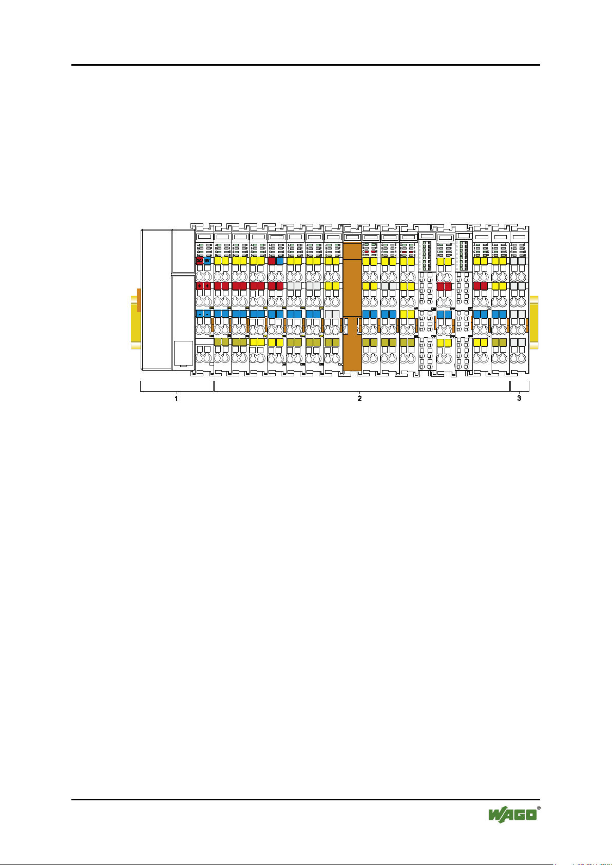
The WAGO-I/O-SYSTEM 750 is a modular, fieldbus-independent input/output
system (I/O system). The configuration described here consists of a fieldbus
coupler/controller (1) and the modular I/O modules (2) for any signal shapes that
form the fieldbus node together. The end module (3) completes the node and is
required for correct operation of the fieldbus node.
Figure 1: Fieldbus Node (Example)
Fieldbus couplers/controllers are available for different fieldbus systems.
Pos: 17.4 /Serie 750 (WAGO-I/O-SYSTEM)/Syste mbes chr ei bung /Ger ät und Sys tem /Sy ste mbes chr ei bung - Besc hr eib ung Auf ba u Fel dbu skn ote n (S tand ard) @ 3\mod_1231493221890_21.docx @ 25870 @ @ 1
The standard fieldbus couplers/controllers contain the fieldbus interface,
electronics and a power supply terminal. The fieldbus interface forms the physical
interface to the relevant fieldbus. The electronics process the data of the I/O
modules and make it available for the fieldbus communication. The 24 V system
supply and the 24 V field supply are fed in via the integrated power supply
terminal.
The fieldbus coupler/controller exchanges process data with the respective control
via the respective fieldbus. The programmable fieldbus controllers (PFC) allow
implementation of additional PLC functions. WAGO-I/O-PRO is used to program
the fieldbus controllers according to IEC 61131-3.
Pos: 17.5 /Serie 750 (WAGO-I/O-SYSTEM)/S yst embes chr ei bung /Ger ät und Sys tem /Sy ste mbes chr ei bung - Ko mmuni kati on Klem menbus , LEDs , 3-Leiter tec h nik @ 3\ mod_1231493520906_21.docx @ 25877 @ @ 1
I/O modules for diverse digital and analog I/O signals as well as special functions
can be connected to the fieldbus coupler/controller. The communication between
the fieldbus coupler/controller and the I/O modules is carried out via an internal
bus.
The components of the WAGO-I/O-SYSTEM 750 have clear termination points,
light emitting diodes for status display, plug-in mini WSB tags and group marker
cards for labeling.
The 1, 2 or 3 wire technology supplemented by a ground wire connection allows
for direct sensor or actuator wiring.
Manual
Version 1.2.0
Page 14

14 System Description WAGO-I/O-SYSTEM 750 XTR
750-xxxx/0040-xxxx Design Notes /XTR
Pos: 17.6 /Serie 750 (WAGO-I/O-SYSTEM)/S yst embes chr ei bung /Ger ät und Sys tem /Sy ste mbes chr ei bung - Ei nführ ung Ser ie 750 XTR @ 27\mod_1468507667008_21.docx @ 216923 @ @ 1
The distinctiveness of the 750 XTR Series lies in its area of application in extreme
environmental conditions. It is extremely temperature-resistant, immune to
interference, as well as insensitive to vibrations and impulse voltages.
The components of the 750 XTR Series are easily recognizable by their dark-gray
housing color.
Pos: 17.7 /Dokumentation allgemein/Gliederungselemente/---Seitenwechsel--- @ 3\mod_1221108045078_0.docx @ 21810 @ @ 1
Manual
Version 1.2.0
Page 15
WAGO-I/O-SYSTEM 750 XTR System Description 15
01
14
01
01
01
(additional positions)
WW
YY
FW --
HW
FL
-
Calendar
Year
Firmware
Hardware
Firmware
version
Internal information
750-xxxx/0040-xxxx Design Notes /XTR
Pos: 17.8 /Al l e Ser ien ( Al lge mei ne M od ule)/Ü ber sc hrift e n/N eue Ü ber schriften/Ebene 2Fertigungsnummer - Überschr ift 2 @ 3\mod_1225444612218_21.docx @ 24889 @ 2 @ 1
3.1 Manufacturing Number
Pos: 17.9.1 /S erie 750 (W AGO- I/O-S YST EM)/G erä te besc hrei bu ng/B edr uc kung /Fer tig ung snu mm er 75 0- xxxx - Einl eit ung FBK/ PFC @ 2 4\mod_1444111422821_21.docx @ 192825 @ @ 1
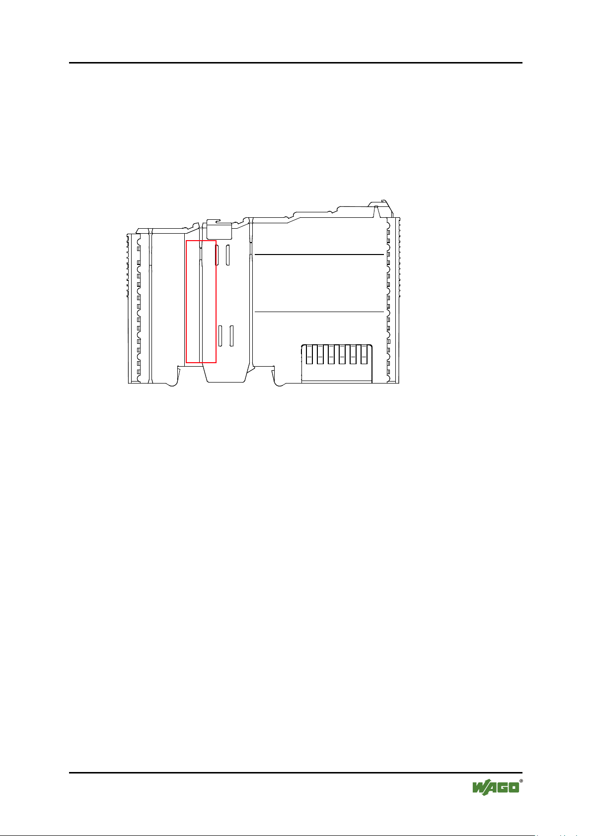
The serial number indicates the delivery status directly after production. This
number is part of the labeling on the side of each component.
In addition, the serial number is printed on the cover cap of the configuration and
programming interface of the fieldbus coupler/controller, so that it can also be
read when installed.
Pos: 17.9.2 /S erie 750 (W AGO- I/O-S YST EM)/G erä te besc hrei bu ng/B edr uc kung /Fer tig ung snu mm er 75 0- xxxx - Abbil dung und Erlä uteru ng @ 24\mod_1443678328855_21.docx @ 192638 @ @ 1
Figure 2: Marking Area for Serial Numbers
There are two serial numbers in two rows in the side marking. They are left of the
release tab. The first 10 positions in the longer row of the serial numbers contain
version and date identifications.
Example structure of the rows: 0114010101…
week
The row order can vary depending on the production year, only the longer row is
relevant. The back part of this and the shorter row contain internal administration
information from the manufacturer.
Pos: 17.10 /D o kum entat io n all ge mei n/Gli ed eru ngsel e ment e/---Sei ten wec hsel --- @ 3\mod_1221108045078_0.docx @ 21810 @ @ 1
version
version
loader
Manual
Version 1.2.0
Page 16
16 System Description WAGO-I/O-SYSTEM 750 XTR
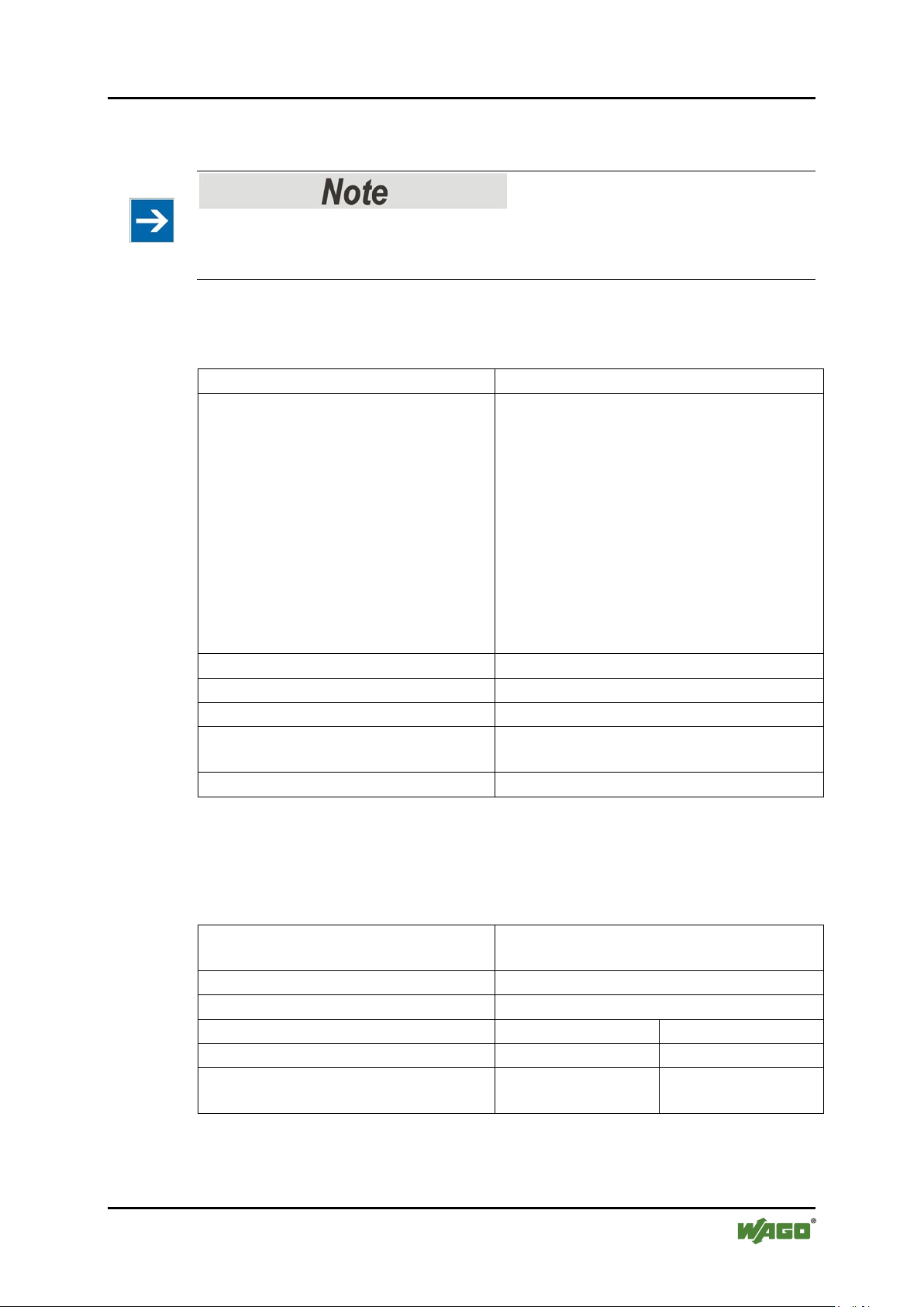
Current Version data for
1. Update
2. Update
3. Update
Production Order
Number
NO
Datestamp
DS
Software index
SW
Hardware index
HW
Firmware loader index
FWL
only for fieldbus
coupler/controller
750-xxxx/0040-xxxx Design Notes /XTR
Pos: 17.11 / Ser ie 750 ( WA GO-I/ O-SY STEM) /Syste mbes chrei bung /Gerä t und Syst em/Ko mpon enten- Upd ate- Matri x a b 20 04 @ 1 6\mod_1373883131873_21.docx @ 126130 @ 2 @ 1
3.2 Component Update
For the case of an update of one component, the lateral marking on each
component contains a prepared matrix.
This matrix makes columns available for altogether three updates to the entry of
the current update data, like production order number (NO), update date (DS),
software version (SW), hardware version (HW) and the firmware loader version
(FWL, if available).
If the update of a component took place, the current version data are registered
into the columns of the matrix.
Additionally with the update of a fieldbus coupler or controller also the cover of
the configuration and programming interface of the fieldbus coupler or fieldbus
controller is printed on with the current manufacturing and production order
number.
The original manufacturing data on the housing of the component remain thereby.
Pos: 17.12 / Ser ie 750 ( WA GO-I/ O-SY STEM) /Syste mbes chrei bung /Gerä t und Syst em/L ageru ng, Kom missi onier ung un d Transp ort @ 3\ mod_1225446600609_21.docx @ 24897 @ 2 @ 1
3.3 Storage, Assembly and Transport
Whenever possible, the components are to be stored in their original packaging.
Likewise, the original packaging provides optimal protection during transport.
When assembling or repacking the components, the contacts must not be soiled or
damaged. The components must be stored and transported in appropriate
containers/packaging. Thereby, the ESD information is to be regarded.
Pos: 17.13 /D o kum entat io n all ge mei n/Gli ed eru ngsel e ment e/---Sei ten wec hsel --- @ 3\mod_1221108045078_0.docx @ 21810 @ @ 1
Pos: 17.14 / Ser ie 750 ( WA GO-I/ O-SY STEM) /Syste mbes chrei bung /Gerä t und Syst em/Au fba urichtli nie n und Nor men @ 3\mod_1231311929250_21.docx @ 25820 @ 2 @ 1
3.4 Assembly Guidelines/Standards
• DIN 60204 Electrical equipment of machines
• DIN EN 50178 Electronic equipment for use in power installations
(replacement for VDE 0160)
Pos: 18 /Dokum entati on allg emei n/Gli ederung sele mente /---Seit enwe chs el--- @ 3\mod_1221108045078_0.docx @ 21810 @ @ 1
Manual
Version 1.2.0
• EN 60439 Low-voltage switchgear and controlgear assemblies
Page 17
WAGO-I/O-SYSTEM 750 XTR System Description 17
Table 3: Technical Data – Mechanics
Material
Polycarbonate, polyamide
Dimensions W × H*) × D:
Fieldbus coupler/controller (standard)
51 mm × 65*) mm × 100 mm
Fieldbus coupler/controller (ECO)
50 mm × 65*) mm × 100 mm
Fieldbus coupler (expanded ECO)
62 mm × 65*) mm × 100 mm
PLC - Controller (PFC200)
79 mm × 65*) mm × 100 mm
112 mm × 65*) mm × 100 mm
I/O module, single
12 mm × 62*) mm × 100 mm
I/O module, double
24 mm × 62*) mm × 100 mm
I/O module, quadruple
48 mm × 62*) mm × 100 mm
Mounting
On TS 35 with locking
stackable due to
Double slot and key connection
Mounting position
Any
Marking
Standard labels and labels for labeling
holders
Protection type
IP20
*)
From upper-edge of DIN 35 rail
Table 4: Technical Data – Electrical Safety
Clearance/creepage distances
Acc. EN 60255-5, EN 60664-1,
EN 50178, IEEE C37.90
Pollution degree
2
Overvoltage category
III
Rated voltage AC/ DC UB
< 50 V
50 V < UB < 250 V
Test voltage
775 VDC
3.5 kVDC
Rated surge voltage
1 kV (EN 60870-2-1
/ Class VW1)
5 kV (EN 60870-2-1
/ Class VW3)
750-xxxx/0040-xxxx Design Notes /XTR
Pos: 19 /Alle S eri en ( Allg emei n e Mod ule) /Ü ber schri fte n/N eue Ü b ersc hrif te n/Eb ene 2Tec hni sch e D aten - Ü bersc hrift 2 @ 3\ mod_1232967587687_21.docx @ 26924 @ 2 @ 1
3.5 Technical Data
Pos: 20.1 /Serie 750 (WAGO-I/O-SYSTEM)/G erät eb eschr ei bung /T echni sc he Da te n/S onst ige/ Hi nweis : A kt uell e Wer te den je weil igen Ha ndb ücher n entn ehm en! @ 3\mod_1232967647578_21.docx @ 26960 @ @ 1
Refer to the relevant manuals for current values!
If the technical data of components differ from the values described here, the
technical data shown in the manuals of the respective components shall be valid.
Pos: 20.2 /Serie 750 (WAGO-I/O-SYSTEM)/G eräte beschr eibu ng/T echnisc he Dat en/S onstig e/Mec hani k, Ansc hl., Kont akte , Klim a, Elektr . Sich erheit , IP XTR @ 17\mod_1389346680484_21.docx @ 141078 @ 3333 @ 1
3.5.1 Mechanics
3.5.2 Electrical Safety
Manual
Version 1.2.0
Page 18

18 System Description WAGO-I/O-SYSTEM 750 XTR
Table 5: Technical Data – Field Wiring
Wire connection
CAGE CLAMP® /
Push-in CAGE CLAMP®
Cross section
0.25 mm² … 2.5 mm², AWG 24 … 14 /
0.25 mm² … 1.5 mm², AWG 24 … 16
Stripped lengths
8 mm … 9 mm / 0.33 in
Table 6: Technical Data – Power Jumper Contacts
Power jumper contacts
Blade/spring contact, self-cleaning
Voltage drop at I
max.
< 1 V/64 modules
Current over power jumper contacts
max.
10 A
Table 7: Technical Data – Internal Bus
Data contacts
Slide contact, hard gold plated,
self-cleaning
Table 8: Technical Data – Climatic Environmental Conditions
Operating temperature range
−40 °C … +70 °C
Storage temperature range
−40 °C … +85 °C
Relative humidity
1)
95 %
Elevation above sea level
max.
5000 m
Stress due to contaminants
Acc. IEC 60068-2-42 and IEC 60068-2-43
Max. contaminant concentration at a
SO2 ≤ 25 ppm
H2S ≤ 10 ppm
Special conditions
The components may not be used without
radiation can occur.
1)
Short-term condensation acc. class 3K7 / IEC EN 60721-3-3 (except wind-driven precipitation,
water and ice formation) permitted
750-xxxx/0040-xxxx Design Notes /XTR
3.5.3 Connection Type
3.5.4 Climatic Environmental Conditions
without temperature derating
with temperature derating
0 m … 2000 m
2000 m … 5000 m: 0.5 K per 100 m
relative humidity < 75%
Pos: 20.3 /Dokumentation allgemein/Gliederungselemente/---Seitenwechsel--- @ 3\mod_1221108045078_0.docx @ 21810 @ @ 1
Manual
Version 1.2.0
additional measures at locations in which
dust, corrosive fumes, gases or ionized
Page 19

WAGO-I/O-SYSTEM 750 XTR System Description 19
750-xxxx/0040-xxxx Design Notes /XTR
Pos: 20.4 /Serie 750 (WAGO-I/O-SYSTEM)/G erät eb eschr ei bung /T echni sc he Da te n/EM V/Ei ns atz ber eich XTR (In dustr ie, Woh nber eich) @ 17 \mod_1389356140919_21.docx @ 141147 @ 3 @ 1
3.5.5 Residential Use
The system with the fieldbus coupler/controller meets the requirements for
interference emissions in residential areas:
• ETHERNET 750-352/040-000
750-880/040-000
750-880/040-001
750-8202/040-000
750-8202/040-001
750-8206/040-000
750-8206/040-001
• CANopen 750-338/040-000
750-838/040-000
With individual approval, the system can also be used for residential use
(residential, business and commercial areas, small business) with other fieldbus
couplers/controllers. The individual approval can be obtained from a
governmental or testing agency. In Germany, the Federal Office for Post and
Telecommunications and its extensions issue the individual approval.
Use of other fieldbus couplers/controllers is possible under certain conditions.
Please contact WAGO Kontakttechnik GmbH & Co. KG.
Pos: 20.5 /Serie 750 (WAGO-I/O-SYSTEM)/G erät eb eschr ei bung /T echni sc he Da te n/A bmess u nge n/Ab mess ung en XTR (sc hmal ) @ 18\ mod _1392189220217_21.docx @ 145161 @ 3 @ 1
Manual
Version 1.2.0
Page 20

20 System Description WAGO-I/O-SYSTEM 750 XTR
750-xxxx/0040-xxxx Design Notes /XTR
3.5.6 Example Dimensions
Figure 3: Dimensions – Nodes with Fieldbus Coupler/Controller (Example)
Pos: 21 /D okum ent atio n al lge mein/ Gli eder ungs ele me nte/---Sei te nwec hsel--- @ 3\ mod_1221108045078_0.docx @ 21810 @ @ 1
Manual
Version 1.2.0
Page 21

WAGO-I/O-SYSTEM 750 XTR Standards and Approvals 21
Table 9: Climatic and Mechanical Environmental Conditions
Range
Acc. Standard
Title
Environmental testing
EN 61131-2
Programmable logic controller, testing
EN 60721-3-1
Environmental conditions – long-term
storage
EN 60721-3-3
Environmental conditions – stationary
use, weather-protected
EN 60870-2-2
Telecontrol equipment – environmental
conditions
EN 61850-3
Communication networks and systems
in stations
IEEE 1613
Environmental and Testing
Requirements in Power Substations
Shipbuilding
Systems for maritime shipping
750-xxxx/0040-xxxx Design Notes /XTR
Pos: 22 /All e S eri en ( Allg emei n e Mod ule) /Ü ber schri fte n/ Ebe ne 1N or men und Z ul ass unge n - Ü bersc hrift 1 @ 15\mod_1366723683236_21.docx @ 117687 @ 1 @ 1
4 Standards and Approvals
Pos: 23.1 /Serie 750 (WAGO-I/O-SYSTEM)/G erät eb eschr ei bung /N ormen un d Ri chtl ini en/ Nor men un d Ric htl ini en 7 5x- xxx Systembesc hreibung @ 18\mod_1393329414685_21.docx @ 146305 @ @ 1
The WAGO-I/O-SYSTEM 750 XTR series was tested according to the following
standards and guidelines. The test values are available in the manual of the
respective I/O module or fieldbus coupler/controller:
Pos: 23.2 /Serie 750 (WAGO-I/O-SYSTEM)/G erät eb eschr ei bung /N ormen un d Ri chtl ini en/ Nor men un d Ric htl ini en XT R - Mech anik un d Klim a Syste mbesc hreib ung @ 18\ mod_1394618852600_21.docx @ 147748 @ @ 1
Pos: 23.3 /Al l e Ser ien ( Al lge mei ne M od ule)/N or me n un d Ric htli ni en/N or men und R ic htli nie n XT R - EMV - S yste mb esc hrei bung @ 16\mod_1378286378361_21.docx @ 130729 @ @ 1
Compliance with the standards is component-dependent
Depending on the selected components, there may be limitations in the
performance of individual EMC standards.
Therefore, observe the section “Standards and Guidelines” in the manual of your
I/O modules or fieldbus coupler/controller!
Manual
Version 1.2.0
Page 22

22 Standards and Approvals WAGO-I/O-SYSTEM 750 XTR
Table 10: EMC
Range
acc. standard
Title
EMC immunity to
EN 61000-6-1
EMC – Generic Standard – Immunity
for residential environments
EN 61000-6-2
EMC – Generic Standard – Immunity
for industrial environments
EN 61131-2
Programmable logic controller – testing
Shipbuilding
Systems for maritime shipping
EN 50121-3-2
EMC – Railway applications –
Apparatus
EN 50121-4
Railway applications – EMC –
Emission and immunity
EN 50121-5
Railway applications – EMC –
Emission and immunity
EN 60255-26
Measuring relays and protection
equipment – EMC
EN 60870-2-1
Telecontrol equipment – EMC
EN 61850-3
Communication networks and systems
in stations – General requirements
IEC 61000-6-5
Immunity for power station and
substation environments
IEEE 1613
Environmental and Testing
Requirements in Power Substations
VDEW: 1994
Digital station technology –
Recommendations
EMC emission of
EN 61000-6-3
EMC – Generic standard – Emission
standard for residential environments
EN 61000-6-4
EMC – Generic standard – Emission
standard for industrial environments
EN 61131-2
Programmable logic controller – testing
Shipbuilding
Systems for maritime shipping
EN 50121-3-2
EMC – Railway applications –
Apparatus
EN 50121-4
Railway applications – EMC –
Emission and immunity
EN 50121-5
Railway applications – EMC –
Emission and immunity
EN 60255-26
Measuring relays and protection
equipment – EMC
EN 60870-2-1
Telecontrol equipment – EMC
EN 61850-3
Communication networks and systems
in stations – General requirements
750-xxxx/0040-xxxx Design Notes /XTR
interference
Pos: 24 /Dokum entati on allg emei n/Gli ederung sele mente /---Seit enwe chs el--- @ 3\mod_1221108045078_0.docx @ 21810 @ @ 1
interference
Manual
Version 1.2.0
Page 23

WAGO-I/O-SYSTEM 750 XTR Assembly 23
750-xxxx/0040-xxxx Design Notes /XTR
Pos: 25 /All e S eri en ( Allg emei n e Mod ule) /Ü ber schri fte n/ Ebe ne 1M on tag e - Ü bersc hri ft 1 @ 1 5\mod_1366723611709_21.docx @ 117655 @ 1 @ 1
5 Assembly
Pos: 26.1 /Serie 750 (WAGO-I/O-SYSTEM)/Montieren/Demontieren/Einbaulage XTR @ 16\mod_1373976754254_21.docx @ 126292 @ 2 @ 1
5.1 Mounting Position
The following mounting positions are approved:
• Lying horizontal
• Standing horizontal
• Vertical
Use an end stop in the case of vertical installation!
When installed vertically, also mount an end stop below the fieldbus node to
protect the fieldbus node against sliding.
WAGO item number 249-116 end stop for TS 35, 6 mm wide
WAGO item number 249-117 end stop for TS 35, 10 mm wide
Pos: 26.2 /Serie 750 (WAGO-I/O-SYSTEM)/Mon tiere n/De monti eren/ Gesam taus bau XTR @ 16 \mod_1373976975062_21.docx @ 126295 @ 2 @ 1
5.2 Overall Configuration
The maximum total length of a fieldbus node without fieldbus coupler/controller
is 780 mm including end module. The width of the end module is 12 mm. When
assembled, the I/O modules have a maximum length of 768 mm.
Examples:
• 64 I/O modules with a 12 mm width can be connected to a fieldbus
coupler/controller.
• 32 I/O modules with a 24 mm width can be connected to a fieldbus
coupler/controller.
Exception:
The number of connected I/O modules also depends on the type of fieldbus
coupler/controller is used. For example, the maximum number of stackable I/O
modules on one PROFIBUS DP/V1 fieldbus coupler/controller is 63 with no
passive I/O modules and end module.
Observe maximum total length of a fieldbus node!
The maximum total length of a fieldbus node without fieldbus coupler/controller
may not exceed 780 mm.
Also note the limitations of individual fieldbus couplers/controllers.
Pos: 26.3 /Serie 750 (WAGO-I/O-SYSTEM )/M on tiere n/D em onti ere n/M ont age auf T r agsc hien e ( XTR) @ 2 4\mod_1444997402760_21.docx @ 193805 @ 233 @ 1
Manual
Version 1.2.0
Page 24

24 Assembly WAGO-I/O-SYSTEM 750 XTR
750-xxxx/0040-xxxx Design Notes /XTR
5.3 Mounting onto Carrier Rail
5.3.1 Carrier Rail Properties
All system components can be snapped directly onto a carrier rail in accordance
with the European standard EN 50022 (DIN 35).
Do not use any third-party carrier rails without approval by WAGO!
WAGO Kontakttechnik GmbH & Co. KG supplies standardized carrier rails that
are optimal for use with the I/O system. If other carrier rails are used, then a
technical inspection and approval of the rail by WAGO Kontakttechnik GmbH &
Co. KG should take place.
Carrier rails have different mechanical and electrical properties. For the optimal
system setup on a carrier rail, certain guidelines must be observed:
• The material must be non-corrosive.
• Most components have a contact to the carrier rail to ground electro-
magnetic disturbances. In order to avoid corrosion, this tin-plated carrier rail
contact must not form a galvanic cell with the material of the carrier rail
which generates a differential voltage above 0.5 V (saline solution of 0.3 %
at 20°C).
• The carrier rail must optimally support the EMC measures integrated into
the system and the shielding of the I/O module connections.
• A sufficiently stable carrier rail should be selected and, if necessary, several
mounting points (every 20 cm) should be used in order to prevent bending
and twisting (torsion).
• The geometry of the carrier rail must not be altered in order to secure the
safe hold of the components. In particular, when shortening or mounting the
carrier rail, it must not be crushed or bent.
• The base of the I/O components extends into the profile of the carrier rail.
For carrier rails with a height of 7.5 mm, mounting points are to be riveted
under the node in the carrier rail (slotted head captive screws or blind
rivets).
• The medal springs on the bottom of the housing must have low-impedance
contact with the DIN rail (wide contact surface is possible).
Manual
Version 1.2.0
Page 25

WAGO-I/O-SYSTEM 750 XTR Assembly 25
Table 11: WAGO DIN Rail
Order number
Description
210-112 /-113
35 × 7.5;
1 mm;
steel yellow chromated; slotted/unslotted
210-197 /-114
35 × 15;
1.5 mm;
steel yellow chromated; slotted/unslotted
210-118
35 × 15;
2.3 mm;
steel yellow chromated; unslotted
210-198
35 × 15;
2.3 mm;
copper; unslotted
210-196
35 × 8.2;
1.6 mm;
aluminum; unslotted
Table 12: Permissible WAGO Carrier Rails When Using XTR PFC200
Item Number
750-8202/040-00x
750-8206/040-00x
210-113 × –
210-114 × –
210-197 × –
210-118 × ×
750-xxxx/0040-xxxx Design Notes /XTR
5.3.2 WAGO DIN Rail
WAGO carrier rails meet the electrical and mechanical requirements shown in the
table below.
Pos: 26.4 /Serie 750 (WAGO-I/O-SYSTEM)/Montieren/Demontieren/Busklemmen 750xxxx/0040xxxx 4g-5g @ 15\mod_1367558844291_21.docx @ 118470 @ @ 1
For vibration loads > 4g, observe the following installation instructions:
• Use pan-head screws or blind rivets at least every 60 mm (12 mm pin
spacing) to secure the DIN rail.
• Make the open conductor length between strain relief and wire connection
as short as possible.
Pos: 26.5 /Serie 750 (WAGO-I/O-SYSTEM)/M onti ere n/D em ontier en/ A uswa hl d er T rag schi ene für XTR- PFC @ 23\mod_1435150387049_21.docx @ 184498 @ @ 1
• Use the reinforced end stop 249-197.
• When using the PFC200 CS 2ETH RS/XTR (750-8202/040-00x), carrier
rails without an oblong hole must also be used. Alternatively, a material
thickness of min. 1.5 mm must be maintained.
• When using the PFC200 CS 2ETH RS CAN DPS/XTR
(750-8206/040-00x), carrier rails without an oblong hole with a material
thickness of min. 2.3 mm must also be used.
Pos: 26.6 /Dokumentation allgemein/Gliederungselemente/---Seitenwechsel--- @ 3\mod_1221108045078_0.docx @ 21810 @ @ 1
Manual
Version 1.2.0
Page 26

26 Assembly WAGO-I/O-SYSTEM 750 XTR
750-xxxx/0040-xxxx Design Notes /XTR
Pos: 26.7 /Serie 750 (WAGO-I/O-SYSTEM)/M onti ere n/D emon tier en/ Abs tän de @ 3\ mod_1225448283750_21.docx @ 24920 @ 2 @ 1
5.4 Spacing
The spacing between adjacent components, cable conduits, casing and frame sides
must be maintained for the complete fieldbus node.
Figure 4: Spacing
The spacing creates room for heat transfer, installation or wiring. The spacing to
cable conduits also prevents conducted electromagnetic interferences from
influencing the operation.
Pos: 26.8 /Dokumentation allgemein/Gliederungselemente/---Seitenwechsel--- @ 3\mod_1221108045078_0.docx @ 21810 @ @ 1
Manual
Version 1.2.0
Page 27

WAGO-I/O-SYSTEM 750 XTR Assembly 27
750-xxxx/0040-xxxx Design Notes /XTR
Pos: 26.9 /Serie 750 (WAGO-I/O-SYSTEM)/M ontier en/D emont ieren/M ont agerei henf olge @ 3\ mod_1231770210031_21.docx @ 25992 @ 2 @ 1
5.5 Mounting Sequence
Fieldbus couplers/controllers and I/O modules of the WAGO-I/O-SYSTEM
750/753 are snapped directly on a carrier rail in accordance with the European
standard EN 50022 (DIN 35).
The reliable positioning and connection is made using a tongue and groove
system. Due to the automatic locking, the individual devices are securely seated
on the rail after installation.
Starting with the fieldbus coupler/controller, the I/O modules are mounted
adjacent to each other according to the project design. Errors in the design of the
node in terms of the potential groups (connection via the power contacts) are
recognized, as the I/O modules with power contacts (blade contacts) cannot be
linked to I/O modules with fewer power contacts.
Pos: 26.10 / Ser ie 750 ( WA GO-I/ O-SY STEM )/ Wichti g e Erl äu ter ung en/Si cher hei ts- und s o nstig e H inw eise /Vor sic ht/ Vors ic ht: V erl etzungsgefahr durch scharfkantige Messerkontakte! @ 6\mod_1256193279401_21.docx @ 43414 @ @ 1
Risk of injury due to sharp-edged blade contacts!
The blade contacts are sharp-edged. Handle the I/O module carefully to prevent
injury.
Pos: 26.11 / Ser ie 750 ( WA GO-I/ O-SY STEM )/ Wichti g e Erl äu ter ung en/Si cher hei ts- und s o nstig e H inw eise /Ac htu ng/Ac ht ung: Bus kl em men nur i n v orges e hen er Rei he nfol ge stec ken! @ 6\mod_1256194177073_21.docx @ 43429 @ @ 1
Insert I/O modules only from the proper direction!
All I/O modules feature grooves for power jumper contacts on the right side. For
some I/O modules, the grooves are closed on the top. Therefore, I/O modules
featuring a power jumper contact on the left side cannot be snapped from the top.
This mechanical coding helps to avoid configuration errors, which may destroy
the I/O modules. Therefore, insert I/O modules only from the right and from the
top.
Pos: 26.12 / Ser ie 750 ( WA GO-I/ O-SY STEM )/ Wichti g e Erl äu ter ung en/Si cher hei ts- und s o nstig e H inw eise /Ac htu ng/Ac ht ung: XTR -Ab schni tte aus schli eßlic h mit XTR- Eins peis e kle mmen begi nn en @ 27\ mod_1468396316258_21.docx @ 216628 @ @ 1
XTR sections begin with XTR supply modules exclusively!
The power jumper contacts of XTR products use a contact material different than
other WAGO-I/O-SYSTEM 750 products.
Connecting power jumper contacts of XTR products to power jumper contacts of
non-XTR products leads to irreversible deterioration in contact characteristics in
the long run.
Therefore, start sections of XTR I/O modules with an XTR supply module.
Only connect XTR I/O modules after XTR supply modules, never otherwise.
Pos: 26.13 / Ser ie 750 ( WA GO-I/ O-SY STEM )/ Wichti g e Erl äu ter ung en/Si cher hei ts- und s o nstig e H inw eise /Hi nwei s/Hi n weis : Bus a bsc hluss XTR nic ht verg ess en! @ 15\mod_1368426836647_21.docx @ 119458 @ @ 1
Manual
Version 1.2.0
Page 28

28 Assembly WAGO-I/O-SYSTEM 750 XTR
750-xxxx/0040-xxxx Design Notes /XTR
Don't forget the bus end module!
Always plug a bus end module 750-600/040-000 onto the end of the fieldbus
node! You must always use this bus end module at all fieldbus nodes with the
WAGO I/O System 750 XTR fieldbus couplers/controllers to guarantee proper
data transfer.
Pos: 26.14 /D o kum entat io n all gem ei n/Gli eder ungs ele ment e/---Sei ten wec hsel --- @ 3\mod_1221108045078_0.docx @ 21810 @ @ 1
Manual
Version 1.2.0
Page 29

WAGO-I/O-SYSTEM 750 XTR Assembly 29
750-xxxx/0040-xxxx Design Notes /XTR
Pos: 26.15 / Ser ie 750 ( WA GO-I/ O-SY STEM) /Monti ere n/De montier en/G erät e einfüge n und ent fern en - Übers chr ift 2 @ 3\mod_1231768483250_21.docx @ 25950 @ 2 @ 1
5.6 Inserting and Removing Devices
Pos: 26.16 / All e S erie n (Al lge mei ne M o dule) /Sic h erhei ts- und sonstige Hinweise/Achtung/Achtung: Arbeiten an Geräten nur spannungsfrei durchführen! @ 6\mod_1256193963573_21.docx @ 43426 @ @ 1
Perform work on devices only if they are de-energized!
Working on energized devices can damage them. Therefore, turn off the power
supply before working on the devices.
Pos: 26.17 / Ser ie 750 ( WA GO-I/ O-SY STEM )/M onti ere n/De monti ere n/F eldb us koppl er/-c ontr oll er ei nf üge n @ 3\mod_1234168173031_21.docx @ 27456 @ 3 @ 1
5.6.1 Inserting the Fieldbus Coupler/Controller
1. When replacing the fieldbus coupler/controller for an already available
fieldbus coupler/controller, position the new fieldbus coupler/controller so
that the tongue and groove joints to the subsequent I/O module are engaged.
2. Snap the fieldbus coupler/controller onto the carrier rail.
3. Use a screwdriver blade to turn the locking disc until the nose of the locking
disc engages behind the carrier rail (see the following figure). This prevents
the fieldbus coupler/controller from canting on the carrier rail.
With the fieldbus coupler/controller snapped in place, the electrical connections
for the data contacts and power contacts (if any) to the possible subsequent I/O
module are established.
Pos: 26.18 / Ser ie 750 ( WA GO-I/ O-SY STEM )/M onti ere n/De monti ere n/V erri egel ung - Bil d (S tand ar d) @ 3\mod_1231768944875_21.docx @ 25953 @ @ 1
Figure 5: Release Tab Standard Fieldbus Coupler/Controller (Example)
Pos: 26.19 / Ser ie 750 ( WA GO-I/ O-SY STEM )/M onti ere n/De monti ere n/F eldb us koppl er/-c ontrol ler ent fer nen @ 4\mod_1239169358453_21.docx @ 30330 @ 3 @ 1
5.6.2 Removing the Fieldbus Coupler/Controller
1. Use a screwdriver blade to turn the locking disc until the nose of the locking
disc no longer engages behind the carrier rail.
2. Remove the fieldbus coupler/controller from the assembly by pulling the
release tab.
Electrical connections for data or power contacts to adjacent I/O modules are
disconnected when removing the fieldbus coupler/controller.
Pos: 26.20 / Ser ie 750 ( WA GO-I/ O-SY STEM) /Monti ere n/De montier en/Bus kle mme einf ügen @ 3\mod_1231769726703_21.docx @ 25989 @ 3 @ 1
Manual
Version 1.2.0
Page 30

30 Assembly WAGO-I/O-SYSTEM 750 XTR
750-xxxx/0040-xxxx Design Notes /XTR
5.6.3 Inserting the I/O Module
1. Position the I/O module so that the tongue and groove joints to the fieldbus
coupler/controller or to the previous or possibly subsequent I/O module are
engaged.
Figure 6: Insert I/O Module (Example)
2. Press the I/O module into the assembly until the I/O module snaps into the
carrier rail.
Figure 7: Snap the I/O Module into Place (Example)
With the I/O module snapped in place, the electrical connections for the data
contacts and power jumper contacts (if any) to the fieldbus coupler/controller or to
the previous or possibly subsequent I/O module are established.
Pos: 26.21 /D o kum entat io n all ge mei n/Gli ed eru ngsel e ment e/---Sei ten wec hsel --- @ 3\mod_1221108045078_0.docx @ 21810 @ @ 1
Manual
Version 1.2.0
Page 31

WAGO-I/O-SYSTEM 750 XTR Assembly 31
750-xxxx/0040-xxxx Design Notes /XTR
Pos: 26.22 / Ser ie 750 ( WA GO-I/ O-SY STEM) /Monti ere n/De montier en/Bus kle mme ent ferne n @ 4\mod_1239169375203_21.docx @ 30334 @ 3 @ 1
5.6.4 Removing the I/O Module
1. Remove the I/O module from the assembly by pulling the release tab.
Figure 8: Removing the I/O Module (Example)
Electrical connections for data or power jumper contacts are disconnected when
removing the I/O module.
Pos: 26.23 / Ser ie 750 ( WA GO-I/ O-SY STEM )/ Wichti g e Erl äu ter ung en/Si cher hei ts- und s o nstig e H inw eise /G efahr /G efahr : V ors ich t bei d er Un ter brec hung v on F E! - XTR @ 18 \mod_1389853538533_21.docx @ 142058 @ @ 1
Use caution when interrupting the FE!
With I/O modules for 220/230 VAC, make sure that people or equipment are not
placed at risk when removing an I/O module and the associated FE interruption
(function grounding). To prevent interruptions, provide ring feeding of the ground
conductor, see section “Grounding”.
Pos: 27 /Dokum entati on allg emei n/Gli ederung sele mente /---Seit enwe chs el--- @ 3\mod_1221108045078_0.docx @ 21810 @ @ 1
Manual
Version 1.2.0
Page 32

32 Connect Devices WAGO-I/O-SYSTEM 750 XTR
750-xxxx/0040-xxxx Design Notes /XTR
Pos: 28 /All e S eri en ( Allg emei n e Mod ule) /Ü ber schri fte n/N eue Ü b ersc hrif te n/Eb ene 1Ger ät e an schl ieß en - Ü b erschr if t 1 @ 3 \mod_1234172889468_21.docx @ 27460 @ 1 @ 1
6 Connect Devices
Pos: 29 /All e S eri en ( Allg emei n e Mod ule)/ Sic her heits- und s onsti ge H in weis e/G efa hr/ Gefa hr: Lei tung en nur i n s pan nung sfr eie m Z usta nd ans chli esse n o der tre nne n @ 16\mod_1372153982130_21.docx @ 124277 @ @ 1
Only connect or disconnect lines when power is safely isolated!
The lines to the device can carry hazardous voltages and currents. Contact with
the lines when live can result in severe injury or death. Therefore, read and
observe the following safety rules before you perform work on the device:
1. Disconnect the respective system component from the power supply.
2. Secure the system component against unintentional restart.
3. Check if the voltage is positively isolated.
Pos: 30.1 /Serie 750 (WAGO-I/O-SYSTEM)/Ans chl ieß en/D aten ko nta kte/Kl em menb us - Ü ber schr ift 2 @ 7\ mod_1266320620183_21.docx @ 50 718 @ 2 @ 1
6.1 Data Contacts/Internal Bus
Pos: 30.2 /Serie 750 (WAGO-I/O-SYSTEM)/G eräte bes chr eibu ng/A nsc hlüs se/D ate nkon takt e - F eldbu s koppler /-c ontr oll er, A b bild ung und Besc hr eibu ng @ 3 \mod_1231771259187_21.docx @ 26002 @ @ 1
Communication between the fieldbus coupler/controller and the I/O modules as
well as the system supply of the I/O modules is carried out via the internal bus. It
is comprised of 6 data contacts, which are available as self-cleaning gold spring
contacts.
Figure 9: Data Contacts
Pos: 30.3 /Serie 750 (WAGO-I/O-SYSTEM)/Wicht ige Erl äuter unge n/Sich erhei ts- u nd so nstig e H in weis e/ Acht ung /Ach tu ng: Buskl em men nic ht a uf Gol dfe der konta kt e leg en! @ 7 \mod_1266318463636_21.docx @ 50695 @ @ 1
Do not place the I/O modules on the gold spring contacts!
Do not place the I/O modules on the gold spring contacts in order to avoid soiling
or scratching!
Pos: 30.4 /Serie 750 (WAGO-I/O-SYST EM)/ Wichti ge Erl äuter unge n/Sich erhei ts- und sonstige Hinweise/Achtung/Achtung: ESD - Auf gute Erdung der Umg ebu ng ac ht en! @ 7\ mod_1266318538667_21.docx @ 50708 @ @ 1
Ensure that the environment is well grounded!
The devices are equipped with electronic components that may be destroyed by
electrostatic discharge. When handling the devices, ensure that the environment
(persons, workplace and packing) is well grounded. Avoid touching conductive
components, e.g. data contacts.
Pos: 30.5 /Dokumentation allgemein/Gliederungselemente/---Seitenwechsel--- @ 3\mod_1221108045078_0.docx @ 21810 @ @ 1
Manual
Version 1.2.0
Page 33

WAGO-I/O-SYSTEM 750 XTR Connect Devices 33
750-xxxx/0040-xxxx Design Notes /XTR
Pos: 30.6 /Serie 750 (WAGO-I/O-SYSTEM)/Ans chl ieß en/ Leis tung skon tak te/F eld versor gu ng - Ü bers chr ift 2 @ 7\mod_1266320656354_21.docx @ 50722 @ 2 @ 1
6.2 Power Contacts/Field Supply
Pos: 30.7 /Serie 750 (WAGO-I/O-SYSTEM)/Wi chtig e Erlä uteru ngen/ Sicher heits- und so nstig e H inw eis e/V orsic ht/ Vor sic ht: Verl etz ungs ge fahr dur ch s ch arf kan tige M es ser kont a kte! @ 6\ mod_1256193279401_21.docx @ 43414 @ @ 1
Pos: 30.8 /Serie 750 (WAGO-I/O-SYSTEM)/G eräte beschr eibu ng/Ans chl üsse/L eistu ngs kontakt e allge mein @ 3\ mod_1231828902046_21.docx @ 26017 @ @ 1
Risk of injury due to sharp-edged blade contacts!
The blade contacts are sharp-edged. Handle the I/O module carefully to prevent
injury.
Self-cleaning power jumper contacts used to supply the field side are located on
the right side of most of the fieldbus couplers/controllers and on some of the I/O
modules. These contacts come as touch-proof spring contacts. As fitting
counterparts the I/O modules have male contacts on the left side.
Figure 10: Example for the Arrangement of Power Contacts
Pos: 30.9 /Dokumentation allgemein/Gliederungselemente/---Seitenwechsel--- @ 3\mod_1221108045078_0.docx @ 21810 @ @ 1
Manual
Version 1.2.0
Page 34

34 Connect Devices WAGO-I/O-SYSTEM 750 XTR
750-xxxx/0040-xxxx Design Notes /XTR
Pos: 30.10 / Ser ie 750 ( WA GO-I/ O-SY STEM )/A nsc hli eße n/Lei ter an CA GE C LAM P a nsc hließ en (all ge mein) - Üb ers chrif t 2 un d Te xt @ 3\mod_1225448660171_21.docx @ 24928 @ 2 @ 1
6.3 Connecting a Conductor to the CAGE CLAMP®
The WAGO CAGE CLAMP® connection is appropriate for solid, stranded and
finely stranded conductors.
Only connect one conductor to each CAGE CLAMP®!
Only one conductor may be connected to each CAGE CLAMP®.
Do not connect more than one conductor at one single connection!
If more than one conductor must be routed to one connection, these must be
connected in an up-circuit wiring assembly, for example using WAGO feedthrough terminals.
1. For opening the CAGE CLAMP® insert the actuating tool into the opening
above the connection.
2. Insert the conductor into the corresponding connection opening.
3. For closing the CAGE CLAMP® simply remove the tool. The conductor is
now clamped firmly in place.
Figure 11: Connecting a Conductor to a CAGE CLAMP
Pos: 31 /Dokum entati on allg emei n/Gli ederung sele mente /---Seit enwe chs el--- @ 3\mod_1221108045078_0.docx @ 21810 @ @ 1
®
Manual
Version 1.2.0
Page 35

WAGO-I/O-SYSTEM 750 XTR Connect Devices 35
750-xxxx/0040-xxxx Design Notes /XTR
Pos: 32 /Ser ie 75 0 (WA GO-I/ O-SYS TEM) /Ans chließ en/L eiter a n Push-in CAGE CL AMP® anschließen - Über sc hrift 2 u nd T e xt @ 6\mod_1258964749000_21.docx @ 44640 @ 2 @ 1
6.4 Connecting a Conductor to the Push-in CAGE
®
CLAMP
The Push-in CAGE CLAMP® connection is appropriate for solid, stranded and
finely stranded conductors.
Only connect one conductor to each Push-in CAGE CLAMP® connection!
Only one conductor may be connected to each Push-in CAGE CLAMP®
connection.
Do not connect more than one conductor at one single connection!
If more than one conductor must be routed to one connection, these must be
connected in an up-circuit wiring assembly, for example using WAGO feedthrough terminals.
Terminate both solid and stranded or ferruled conductors by simply pushing them
in - no tool required. For all other types of conductors, Push-in CAGE CLAMP®
must be opened for connection with an operating tool with a 2.5 mm blade (order
no. 210-719).
1. To open the Push-in CAGE CLAMP® insert the actuating tool into the
opening above the connection.
2. Insert the conductor into the corresponding connection opening.
3. To close the Push-in CAGE CLAMP® simply remove the tool - the
conductor is then clamped firmly in place.
Figure 12: Connecting a Conductor to a Push-in CAGE CLAMP
®
Pos: 33 /Dokum entati on allg emei n/Gli ederung sele mente /---Seit enwe chs el--- @ 3\mod_1221108045078_0.docx @ 21810 @ @ 1
Manual
Version 1.2.0
Page 36

36 Connect Devices WAGO-I/O-SYSTEM 750 XTR
750-xxxx/0040-xxxx Design Notes /XTR
Pos: 34.1 /Serie 750 (WAGO-I/O-SYSTEM)/S yste mbesc hrei b ung/ Vers orgu ng/S pan nung sv ersor gung - Üb erschr ift 2 @ 3\mod_1232950078953_21.docx @ 26680 @ 2 @ 1
6.5 Power Supply
Pos: 34.2 /Serie 750 (WAGO-I/O-SYSTEM)/Syst embes chrei bung /Vers orgu ng/Pot enti altren nung @ 3\mod_1232950094125_21.docx @ 26732 @ 3 @ 1
6.5.1 Isolation
Within the fieldbus node, there are three electrically isolated potentials:
• Electrically isolated fieldbus interface via transformer
• Electronics of the fieldbus couplers/controllers and the I/O modules
(internal bus)
• All I/O modules have an electrical isolation between the electronics
(internal bus, logic) and the field electronics. Some digital and analog input
modules have each channel electrically isolated, please see catalog.
Pos: 34.3 /Serie 750 (WAGO-I/O-SYSTEM)/S yste mbesc hrei b ung/ Vers orgu ng/P ot ential tr ennung - Bi ld (St and ard + er weit ert er E CO) @ 3\mod_1232950095187_21.docx @ 26740 @ @ 1
Figure 13: Isolation for Fieldbus Couplers/Controllers (Example)
Pos: 34.4 /Dokumentation allgemein/Gliederungselemente/---Seitenwechsel--- @ 3\mod_1221108045078_0.docx @ 21810 @ @ 1
Manual
Version 1.2.0
Page 37

WAGO-I/O-SYSTEM 750 XTR Connect Devices 37
Table 13: Legend for Figure “System Voltage for Fieldbus Couplers/Controllers”
Position
Description
1
System supply DC 24 V
2
System supply 0 V
750-xxxx/0040-xxxx Design Notes /XTR
Pos: 34.5 /Serie 750 (WAGO-I/O-SYST EM) /S yste mbesc hrei bung /Ver sor gu ng/S yste mver sor gung - Üb ersc hrif t 3 @ 3 \mod_1232950096265_21.docx @ 26748 @ 3 @ 1
6.5.2 System Supply
Pos: 34.6 /Serie 750 (WAGO-I/O-SYSTEM)/S yste mbesc hrei b ung/ Vers orgu ng/S yste mver sor gung - A nsc hluss @ 3\mod_1232950096796_21.docx @ 26752 @ 4 @ 1
6.5.2.1 Connection
The WAGO-I/O-SYSTEM 750 requires a 24 V direct current system supply.
The power supply is provided via the fieldbus coupler/controller and, if necessary,
in addition via internal system supply modules 750-613. The power supply is
reverse voltage protected.
Do not use an incorrect voltage/frequency!
The use of an incorrect supply voltage or frequency can cause severe damage to
the components.
Pos: 34.7 /Serie 750 (WAGO-I/O-SYSTEM)/S yste mbeschr eib ung/Ver sorg ung/S ystem vers orgung XTR - Ans chl uss - S yst em vers org ung (St and ard + er wei ter ter ECO) mi t LW L-Anz eige @ 16\mod_1373884059484_21.docx @ 126140 @ @ 1
Figure 14: System Voltage for Fieldbus Couplers/Controllers (Example)
Pos: 34.8 /Serie 750 (WAGO-I/O-SYSTEM)/S yste mbesc hrei b ung/ Vers orgu ng/S yste mver sor gung - A nsc hluss - Die eing es peis te 2 4 V- Glei chsp annung versor gt... @ 3\mod_1232950097328_21.docx @ 26756 @ @ 1
The fed DC 24 V supplies all internal system components, e.g. fieldbus
coupler/controller electronics, fieldbus interface and I/O modules via the internal
bus (5 V system voltage). The 5 V system voltage is galvanically connected to the
24 V system supply.
Pos: 34.9 /Serie 750 (WAGO-I/O-SYSTEM)/S yste mbeschr eib ung/Ver sorg ung/S ystem vers orgung XTR - Ans chl uss - S yst ems pa nnu ng (S tan dar d + er w eiter ter ECO ) o B @ 16\mod_1373884429295_21.docx @ 126143 @ @ 1
Manual
Version 1.2.0
Page 38

38 Connect Devices WAGO-I/O-SYSTEM 750 XTR
Table 14: Alignment
Internal current
consumption*)
Current consumption via system voltage (5 V for electronics
of I/O modules and fieldbus coupler/controller).
Total current
Available current for the I/O modules. Provided by the bus
internal system supply module
*)
See current catalog, manuals, Internet
750-xxxx/0040-xxxx Design Notes /XTR
Figure 15: System Supply for Fieldbus Coupler/Controller
Pos: 34.10 / Ser ie 750 ( WA GO-I/ O-SY STEM )/S yste mbes chr eibu ng/V ers org ung/ Syst em versor gu ng - Ans chl uss - H i nwei s: Gleic hz. Rü ckse tz en al ler Ver sorg ung s modul e @ 3\mod_1232950097906_21.docx @ 26760 @ @ 1
Only reset the system simultaneously for all supply modules!
Reset the system by switching the system supply simultaneously at all supply
modules (fieldbus coupler/controller and potential supply module with bus power
supply) off and on again.
Pos: 34.11 / Ser ie 750 ( WA GO-I/ O-SY STEM )/S yste mbes chr eibu ng/V ers org ung/ Systemversorgung - Auslegung @ 3\mod_1232950104812_21.docx @ 26780 @ 4 @ 1
6.5.2.2 Dimensioning
Recommendation
A stable power supply cannot always be assumed. Therefore, you should use
regulated power supplies to ensure the quality of the supply voltage.
The supply capacity of the fieldbus coupler/controller or the internal system
supply module can be taken from the technical data of the components.
for I/O modules*)
Pos: 34.12 /D o kum entat io n all ge mei n/Gli ed eru ngsel e ment e/---Sei ten wec hsel --- @ 3\mod_1221108045078_0.docx @ 21810 @ @ 1
power supply unit. See fieldbus coupler/controller and
Manual
Version 1.2.0
Page 39

WAGO-I/O-SYSTEM 750 XTR Connect Devices 39
750-xxxx/0040-xxxx Design Notes /XTR
Pos: 34.13 /Ser ie 750 (W AGO- I/O-SY ST EM)/S yst emb esc hrei bu ng/V ers org ung/ Beis pi el: @ 3 \mod_1232630417843_21.docx @ 26605 @ @ 1
Example:
Pos: 34.14 / Ser ie 750 ( WA GO-I/ O-SY STEM )/S yste mbes chr eibu ng/V ers org ung/ Syst em versor gu ng - Aus leg ung - Beis pi el 1 ( er weit ert er EC O) @ 3 \mod_1232950106250_21.docx @ 26788 @ @ 1
Calculating the current consumption on an Example Coupler:
Internal current consumption 380 mA at 5 V
Residual current for bus modules 1620 mA at 5 V
Sum I
Pos: 34.15 /Ser ie 750 (W AGO- I/O-SY STEM )/S yste mb eschr eibu ng/V ers org ung/ Syst em versor gu ng - A usleg ung - Interne Stromaufnahme/Summenstrom @ 3\mod_1232950111375_21.docx @ 26816 @ @ 1
(5 V) total
2000 mA at 5V
The internal current consumption is indicated in the technical data for each bus
terminal. In order to determine the total requirement, add together the values of all
I/O modules in the node.
Please note the aggregate current for I/O modules. It may be necessary to
supply potential!
When the sum of the internal current consumption for the I/O modules exceeds
their aggregate current, you must use a supply module with bus power supply.
Install it before the position where the permissible aggregate current would be
exceeded.
Pos: 34.16 / Ser ie 750 ( WA GO-I/ O-SYST EM) /Sys tem besc hr eibu ng/V ers or gung /Bei spi el: @ 3 \mod_1232630417843_21.docx @ 26605 @ @ 1
Pos: 34.17 / Ser ie 750 ( WA GO-I/ O-SY STEM) /Syste mbes chrei bung /Vers orgung /Syst emv ersorg ung XTR - Ausleg ung - Bei spi el 2 ( er weit ert er EC O) @ 16\mod_1373894651926_21.docx @ 126155 @ @ 1
Pos: 34.18 / Ser ie 750 ( WA GO-I/ O-SY STEM )/S yste mbes chr eibu ng/V ers org ung/ Syst em versor gu ng - Aus leg ung - Berechnung Eingangsstrom XTR @ 18\mod_1392381249671_21.docx @ 145538 @ @ 1
Example:
Calculating the total current on the Example Coupler described above:
A node with the example coupler, which is described above, consists of:
• 20 relay modules (750-517/xxx-xxx)
• 10 digital input modules (750-1415/xxx-xxx).
Internal current consumption 20 * 90 mA = 1800 mA
10 * 6 mA = 60 mA
Sum 1860 mA
The example coupler can provide 1620 mA (see previous example) for the bus
modules. This value is given in the associated data sheet. Consequently, an
internal system supply module (750-613/xxx-xxx), e. g. in the middle of the node,
should be added.
The maximum input current of the 24 V system supply is 500 mA. The exact
electrical consumption (I
) can be determined with the following formulas:
(V)
Manual
Version 1.2.0
Page 40

40 Connect Devices WAGO-I/O-SYSTEM 750 XTR
Fieldbus coupler or controller
I
=
Sum of all the internal current consumption of the connected
coupler/controller
Internal system supply module
I
=
Sum of all the internal current consumption of the connected
5 V
I
(5 V) total
24 V
η
(87 % Efficiency of the power supply at nominal load 24 V)
750-xxxx/0040-xxxx Design Notes /XTR
(5 V) total
bus modules + internal current consumption fieldbus
(5 V) total
bus modules at internal system supply module
Input current I
Pos: 34.19 / Ser ie 750 ( WA GO-I/ O-SY STEM )/S yste mbes chr eibu ng/V ers org ung/ Syst em versor gu ng - Aus leg ung - n=0, 8 7 (87% Ne tzt eil wir kung sg rad b ei 2 4 V) @ 3 \mod_1232950112718_21.docx @ 26824 @ @ 1
Pos: 34.20 / Ser ie 750 ( WA GO-I/ O-SY STEM )/S yste mbes chr eibu ng/V ers org ung/ Syst em versor gu ng - Aus leg ung - Hinweis: Bei Test der Stromaufnahme Ausgänge ak tiviere n @ 3\mod_1232950110750_21.docx @ 26812 @ @ 1
Activate all outputs when testing the current consumption!
If the electrical consumption of a power supply point for the 24 V system
supply exceeds 500 mA, then the cause may be an improperly dimensioned
node or a defect.
During the test, you must activate all outputs.
Pos: 34.21 /Dokumentation allgemein/Gl i eder ung sel ement e/---S eit enwec hs el--- @ 3\ mod_1221108045078_0.docx @ 21810 @ @ 1
(24 V)
=
η = 0.87
*
Manual
Version 1.2.0
Page 41

WAGO-I/O-SYSTEM 750 XTR Connect Devices 41
Table 15: Legend for Figure “Field Supply for Fieldbus Couplers/Controllers”
Position
Description
1
Field supply 24 VDC
2
Field supply 0 V
3
Power jumper contacts (potential distribution to adjacent I/O modules)
750-xxxx/0040-xxxx Design Notes /XTR
Pos: 34.22 / Ser ie 750 ( WA GO-I/ O-SY STEM )/S yste mbes chr eibu ng/V ers org ung/F eld vers org ung - Über schr ift 3 @ 3\mod_1232950080953_21.docx @ 26688 @ 3 @ 1
6.5.3 Field Supply
Pos: 34.23 / Ser ie 750 ( WA GO-I/ O-SY STEM )/S yste mbes chr eibu ng/V ers org ung/F eld vers org ung - Ansc hlus s @ 3\mod_1232950082031_21.docx @ 26696 @ 4 @ 1
6.5.3.1 Connection
Sensors and actuators can be directly connected to the relevant channel of the I/O
module in 1, 2, 3 or 4 conductor connection technology. The I/O module supplies
power to the sensors and actuators. The input and output drivers of some I/O
modules require the field side supply voltage.
Pos: 34.24 / Ser ie 750 ( WA GO-I/ O-SYSTEM)/Systembeschreibung/Vers org ung/F eld vers org ung - Ansc hluss - Ei nspei s ung felds ei tig ( St and ard + er weit ert er EC O) @ 3\ mod_1232950087703_21.docx @ 26712 @ @ 1
The fieldbus coupler/controller provides field side power (DC 24 V). In this case
it is a passive power supply without protection equipment.
Pos: 34.25 / Ser ie 750 ( WA GO-I/ O-SY STEM )/S yste mbes chr eibu ng/V ers org ung/F eld vers org ung - Ansc hluss - P otenti algru ppen mi t Eins peise klemm e XTR @ 17\ mod_1382697121058_21.docx @ 135120 @ @ 1
Power supply modules with or without diagnostic capability are available for the
power supply of other field potentials (e.g. 24 VDC, 0 VAC/DC … 230 VAC/DC,
120 VAC, 230 VAC). The power supply modules can also be used to set up
various potential groups. The connections are connected in pairs to a power
contact.
Pos: 34.26 / Ser ie 750 ( WA GO-I/ O-SY STEM) /Syste mbes chrei bung /Vers orgung /Feld vers orgung XTR - Ans chl uss - Bil d: Fel d vers orgu ng ( St an dard + er weit ert er EC O) @ 1 6\mod_1373895183197_21.docx @ 126188 @ @ 1
Figure 16: Field Supply for Fieldbus Couplers/Controllers (Example)
Pos: 34.27 / Ser ie 750 ( WA GO-I/ O-SY STEM )/S yste mbes chr eibu ng/V ers org ung/F eld vers org ung - Ansc hluss -W eiterl eitu ng Versor gung sspg ., Strom belas tung 10 A, neue Ei nspei sekle mme @ 8\ mod_1279805441785_21.docx @ 60845 @ @ 1
The field-side power supply is automatically derived from the power jumper
contacts when snapping an I/O module.
The current load of the power contacts must not exceed 10 A on a continual basis.
Manual
Version 1.2.0
Page 42

42 Connect Devices WAGO-I/O-SYSTEM 750 XTR
establish the ground connection when the connection to the power jumper
750-xxxx/0040-xxxx Design Notes /XTR
By inserting an additional power supply module, the field supply via the power
contacts is disrupted. From there a new power supply occurs which may also
contain a new voltage potential.
Pos: 34.28 / Ser ie 750 ( WA GO-I/ O-SY STEM )/S yste mbes chr eibu ng/V ers org ung/F eld vers org ung - Ansc hluss - 2 H in weis e: Pote nti al neu eins peis en + Di st anzkl em me @ 3\ mod_1232950091343_21.docx @ 26724 @ @ 1
Recontacts is disrupted!
Some I/O modules have no or very few power contacts (depending on the I/O
function). Due to this, the passing through of the relevant potential is disrupted. If
you require a field supply via power jumper contacts for subsequent I/O modules,
then you have to use a power supply module.
Note the data sheets of the I/O modules.
Use a spacer module when setting up a node with different potentials!
In the case of a node setup with different potentials, e.g. the alteration from
DC 24 V to AC 230 V, you should use a spacer module. The optical separation of
the potentials acts as a warning to heed caution in the case of wiring and
maintenance works. Thus, you can prevent the results of wiring errors.
Pos: 34.29 / Ser ie 750 ( WA GO-I/ O-SY STEM) /Syste mbes chrei bung /Vers orgung /Feld vers orgung XTR - Abs icher ung @ 16 \mod_1373895529559_21.docx @ 126191 @ 4 @ 1
6.5.3.2 Fusing
Fusing has to be done externally. The fuse modules of the WAGO series 281 and
282 are suitable for this purpose.
Figure 17: Fuse Modules for Automotive Fuses, Series 282
Figure 18: Fuse Modules for Automotive Fuses, Series 2006
Manual
Version 1.2.0
Page 43

WAGO-I/O-SYSTEM 750 XTR Connect Devices 43
750-xxxx/0040-xxxx Design Notes /XTR
Figure 19: Fuse Modules with Pivotable Fuse Carrier, Series 281
Figure 20: Fuse Modules with Pivotable Fuse Carrier, Series 2002
Pos: 34.30 /D o kum entat io n all ge mei n/Gli ed eru ngsel e ment e/---Sei ten wec hsel --- @ 3\mod_1221108045078_0.docx @ 21810 @ @ 1
Manual
Version 1.2.0
Page 44

44 Connect Devices WAGO-I/O-SYSTEM 750 XTR
Table 16: XTR Supply Modules for Powering XTR Sections
Item No.
Description
Description
750-626/040-000
Power supply filter
System and field supply with filtering
(750-613/040-000)
750-624/040-001
Field-side power
supply filter
24V field supply with filtering
750-602/040-000
Supply module
24 VDC power supply
750-612/040-000
Supply module
0-240 VAC/DC power supply
750-613/040-000
Supply module
24 VDC bus power supply
750-xxxx/0040-xxxx Design Notes /XTR
Pos: 34.31 /Ser ie 750 (W AGO- I/O-SY STEM) /Syst embes chrei bung /Vers orgung /Misc hbe trieb XTR mit St andar d-Buskl emme n der Ser ien 75 0/753 @ 2 7\mod_1468333111049_21.docx @ 216609 @ 3 @ 1
6.5.4 Power Supply for Mixed Operation
In a node, WAGO-I/O-SYSTEM 750 XTR and WAGO-I/O-SYSTEM 750
products can be used in mixed operation. The permitted environmental conditions
of the node, e.g., the temperature range, then follow the components with the least
ruggedness.
In mixed operation, it should also be noted that an XTR power supply must be
connected before an XTR section and a standard supply module before a standard
section.
(24 V, 0 V), i.e., fieldbus coupler/
controller and bus power supply
Pos: 34.32 / Ser ie 750 ( WA GO-I/ O-SY STEM )/ Wichti g e Erl äu ter ung en/Si cher hei ts- und s o nstig e H inw eise /Ac htu ng/Ac ht ung: XTR -Ab schni tte aus schli eßlich mit XTR-Einspeis e kle mmen begi nn en @ 27\ mod_1468396316258_21.docx @ 216628 @ @ 1
XTR sections begin with XTR supply modules exclusively!
The power jumper contacts of XTR products use a contact material different than
other WAGO-I/O-SYSTEM 750 products.
Connecting power jumper contacts of XTR products to power jumper contacts of
non-XTR products leads to irreversible deterioration in contact characteristics in
the long run.
Therefore, start sections of XTR I/O modules with an XTR supply module.
Only connect XTR I/O modules after XTR supply modules, never otherwise.
Pos: 34.33 /D o kum entat io n all gem ei n/Gli eder ungs ele ment e/---Sei ten wec hsel --- @ 3\mod_1221108045078_0.docx @ 21810 @ @ 1
Manual
Version 1.2.0
Page 45

WAGO-I/O-SYSTEM 750 XTR Connect Devices 45
Table 17: Filter Modules for 24 V Power Supply
Item No.
Description
Description
750-626/040-000
Power supply
System and field supply with filtering (24 V,
power supply (750-613/040-000)
750-624/040-001
Field-side
filter
24 V field supply with filtering
750-xxxx/0040-xxxx Design Notes /XTR
Pos: 34.34 / Ser ie 750 ( WA GO-I/ O-SY STEM) /Syste mbes chrei bung /Vers orgung /Erg änze nde Eins peis evors chrift en XTR (S tandar d) @ 16\ mod_1373896786700_21.docx @ 126194 @ 3 @ 1
6.5.5 Supplementary Power Supply Regulations
The WAGO-I/O-SYSTEM 750 XTR can also be used in shipbuilding applications
and onshore/offshore installations (e.g., platforms, loading facilities), as well as in
telecontrol applications. This is possible via certification under the standards of
leading agencies such as Germanischer Lloyd and Lloyds Register.
For standard-compliant application in substation instrumentation and control,
telecontrol systems, railway technology or shipbuilding certified operation, fieldside power supply filter 750-624/040-001 or power supply filter 750-626/040-000
are generally to be used for XTR module groups.
filter
0 V), i.e., fieldbus coupler/controller and bus
power supply
Therefore, the following power supply requirements must be observed:
Figure 21: Power Supply Concept
The 24 V system power supply for the fieldbus coupler/controller must be filtered
and protected against overvoltage. Therefore, the power must be supplied via
power supply filter 750-626/040-000.
Manual
Version 1.2.0
Page 46

46 Connect Devices WAGO-I/O-SYSTEM 750 XTR
750-xxxx/0040-xxxx Design Notes /XTR
The 24 V field power supply systems must be protected against overvoltage.
Therefore, the power must be supplied via field-side power supply filter
750-624/040-001 or power supply filter 750-626/ 040-000.
For this potential group, only the supply module 750-612/040-000 is required for
a 230 V field power supply.
Pos: 34.35 /D o kum entat io n all ge mei n/Gli ed eru ngsel e ment e/---Sei ten wec hsel --- @ 3\mod_1221108045078_0.docx @ 21810 @ @ 1
Manual
Version 1.2.0
Page 47

WAGO-I/O-SYSTEM 750 XTR Connect Devices 47
750-xxxx/0040-xxxx Design Notes /XTR
Pos: 34.36 /Ser ie 750 (W AGO- I/O-SY STEM )/S yste mb eschr eibu ng/V ers org ung/ Vers org ung sbei spiel - Überschrift + Hinweis @ 3\mod_1232949833531_21.docx @ 26670 @ 3 @ 1
6.5.6 Supply Example
SupplSggggggggggggggggg
The system supply and the field supply shall be separated!
You should separate the system supply and the field supply in order to ensure bus
operation in the event of a short-circuit on the actuator side.
Pos: 34.37 / Ser ie 750 ( WA GO-I/ O-SY STEM )/S yste mbes chr eibu ng/V ers org ung/ Vers org ungs beis piel - Bild XTR @ 18\mod_1393260466178_21.docx @ 146269 @ @ 1
Figure 22: Power Supply Example
Pos: 34.38 / Ser ie 750 ( WA GO-I/ O-SY STEM )/S yste mbes chr eibu ng/V ers org ung/ Vers org ungs beis piel - Leg end e zu Abbild ung "V ersorg ungs beis piel XTR" @ 18\mod_1393260531676_21.docx @ 146272 @ @ 1
Manual
Version 1.2.0
Page 48

48 Connect Devices WAGO-I/O-SYSTEM 750 XTR
Table 18: Legend for Figure “Power Supply Example”
Item
Description
1
Power supply on the fieldbus coupler/controller via external system
supply module
2
Supply module 24 V
3
Supply module with bus power supply 24 V
4
Separation module recommended
5
Supply module 230 V
750-xxxx/0040-xxxx Design Notes /XTR
Pos: 34.39 /D o kum entat io n all ge mei n/Gli ed eru ngsel e ment e/---Sei ten wec hsel --- @ 3\mod_1221108045078_0.docx @ 21810 @ @ 1
Manual
Version 1.2.0
Page 49

WAGO-I/O-SYSTEM 750 XTR Connect Devices 49
Table 19: WAGO Power Supply Units
Item number
Description
787-822/xxx-xxx
Primary switch-mode power supply EPSITRON® PRO Power,
24 VDC / 5 A*), nominal input voltage 100 VAC … 240 VAC
787-832/xxx-xxx
Primary switch-mode power supply EPSITRON® PRO Power,
24 VDC / 10 A*), nominal input voltage 110 VAC … 240 VAC
787-840/xxx-xxx
Primary switch-mode power supply EPSITRON® PRO Power,
400 VAC … 500 VAC
*)
Derating −3 %/K > +50 °C
750-xxxx/0040-xxxx Design Notes /XTR
Pos: 34.40 / Ser ie 750 ( WA GO-I/ O-SY STEM) /Syste mbes chrei bung /Vers orgung /Netz gerät e XTR @ 16 \mod_1373963895846_21.docx @ 126216 @ 3 @ 1
6.5.7 Power Supply Units
The WAGO-I/O-SYSTEM 750 XTR requires 24 VDC voltage (system supply)
for operation.
Recommendation
A stable power supply cannot always be assumed everywhere. Therefore, you
should use regulated power supplies to ensure the quality of the supply voltage
(see also table “WAGO power supply units”).
For brief voltage dips, a buffer (200 µF per 1 A load current) must be provided.
Buffer for system power supply!
The system power supply must be buffered to bridge power outages. As the power
demand depends on the respective node configuration, buffering is not
implemented internally.
To achieve power outages of 1 ms to 10 ms according to IEC61131-2, determine
the buffering appropriate for your node configuration and structure it as an
external circuit.
The power demand must be determined individually depending on the entry point
of the field supply. All loads through field devices and I/O modules must be taken
into account. The field supply also impacts the I/O modules because the input and
output drivers of some I/O modules require the voltage of the field supply.
System and field supply must be isolated!
The system supply and field supply must be isolated to ensure bus operation in the
event of short circuits on the actuator side.
24 VDC / 10 A*), nominal input voltage 3×
Pos: 34.41 /D o kum entat io n all ge mei n/Gli ed eru ngsel e ment e/---Sei ten wec hsel --- @ 3\mod_1221108045078_0.docx @ 21810 @ @ 1
Manual
Version 1.2.0
Page 50

50 Connect Devices WAGO-I/O-SYSTEM 750 XTR
Table 20: WAGO Ground Wire Terminals
Order No.
Description
283-609
1-conductor ground (earth) terminal block make an automatic contact
Note: Also order the end and intermediate plate (283-320).
750-xxxx/0040-xxxx Design Notes /XTR
Pos: 34.42 /Ser ie 750 (W AGO- I/O-SY STEM) /Syst embes chrei bung /Vers orgung /Erd ung @ 3\mod_1231246555687_21.docx @ 25802 @ 23443 @ 1
6.6 Grounding
6.6.1 Grounding the DIN Rail
6.6.1.1 Framework Assembly
When setting up the framework, the carrier rail must be screwed together with the
electrically conducting cabinet or housing frame. The framework or the housing
must be grounded. The electrical connection is established via the screw. Thus,
the carrier rail is grounded.
Ensure sufficient grounding is provided!
You must take care to ensure the flawless electrical connection between the
carrier rail and the frame or housing in order to guarantee sufficient grounding.
6.6.1.2 Insulated Assembly
Insulated assembly has been achieved when there is constructively no direct
ohmic contact between the cabinet frame or machine parts and the carrier rail.
Here, the earth ground must be set up via an electrical conductor in accordance
with valid national safety regulations.
Recommendation
The optimal setup is a metallic assembly plate with grounding connection which
is electrically conductive linked to the carrier rail.
The separate grounding of the carrier rail can be easily set up with the aid of the
WAGO ground wire terminals.
to the carrier rail; conductor cross section: 0.2 mm² … 16 mm2
Manual
Version 1.2.0
Page 51

WAGO-I/O-SYSTEM 750 XTR Connect Devices 51
750-xxxx/0040-xxxx Design Notes /XTR
6.6.2 Grounding Function
The grounding function increases the resistance against electro-magnetic
interferences. Some components in the I/O system have a carrier rail contact that
dissipates electro-magnetic interferences to the carrier rail.
Figure 23: Carrier Rail Contact (Example)
Ensure sufficient grounding is provided!
You must take care to ensure the direct electrical connection between the carrier
rail contact and the carrier rail.
The carrier rail must be grounded.
For information on carrier rail properties, see section “Mounting” > … > “Carrier
Rail Properties”.
The bottom CAGE CLAMP
connection of a field-side functional ground. This potential is made available to
the I/O module arranged on the right through the spring-loaded contact of the
three power contacts. Some I/O modules are equipped with a knife-edge contact
that taps this potential. This forms a potential group with regard to functional
ground with the I/O module arranged on the left.
Pos: 34.43 /D o kum entat io n all ge mei n/Gli ed eru ngsel e ment e/---Sei ten wec hsel --- @ 3\mod_1221108045078_0.docx @ 21810 @ @ 1
®
connectors of the supply modules enable optional
Manual
Version 1.2.0
Page 52

52 Connect Devices WAGO-I/O-SYSTEM 750 XTR
750-xxxx/0040-xxxx Design Notes /XTR
Pos: 34.44 / Ser ie 750 ( WA GO-I/ O-SY STEM) /Syste mbes chrei bung /Vers orgung /Sc hirmung @ 3\mod_1231251994828_21.docx @ 25813 @ 23333 @ 1
6.7 Shielding
6.7.1 General
Use of shielded cables reduces electromagnetic interference and thus increases
signal quality. Measurement errors, data transmission errors and interference due
to excessive voltage can be prevented.
Connect the cable shield to the ground potential!
Integrated shielding is mandatory to meet the technical specifications in regards to
measuring accuracy. Connect the cable shield and ground potential at the inlet to
the cabinet or housing. This allows induced interference to dissipate and to be
kept away from devices in the cabinet or housing.
Figure 24: Cable Shield at Ground Potential
Improve shielding performance by placing the shield over a large area!
Higher shielding performance is achieved via low-impedance connection between
shield and ground. For this purpose, connect the shield over a large surface area,
e.g., WAGO shield connecting system. This is especially recommended for largescale systems where equalizing current or high impulse-type currents caused by
atmospheric discharge may occur.
Keep data and signal lines away from sources of interference!
Route data and signal lines separately from all high voltage cables and other
sources of high electromagnetic emission (e.g., frequency converter or drives).
6.7.2 Bus Cables
The shielding of the bus line is described in the respective configuration
guidelines and standards of the bus system.
Manual
Version 1.2.0
Page 53

WAGO-I/O-SYSTEM 750 XTR Connect Devices 53
Figure 25: Examples of the WAGO Shield Connecting System
750-xxxx/0040-xxxx Design Notes /XTR
6.7.3 Signal Lines
I/O modules for analog signals and some interface I/O modules are equipped with
shield clamps.
Use shielded signal lines!
Only use shielded signal lines for analog signals and I/O modules which are
equipped with shield clamps. Only then can you ensure that the accuracy and
interference immunity specified for the respective I/O module can be achieved
even in the presence of interference acting on the signal cable.
6.7.4 WAGO Shield Connecting System
The WAGO shield connecting system consists of shield clamping saddles,
busbars and various mounting carriers. These components can be used to achieve
many different configurations.
Figure 26: Application of the WAGO Shield Connecting System
=== Ende der Li st e für Te xtm arke Inh alt _mit te = ==
Manual
Version 1.2.0
Page 54

54 List of Figures WAGO-I/O-SYSTEM 750 XTR
750-xxxx/0040-xxxx Design Notes /XTR
Pos: 36 /Dokum entati on allg emei n/Verz eichni sse/ Abbil dung sverz eichni s - Über schri ft oG un d Verzei chnis @ 3\mod_1219222916765_21.docx @ 21080 @ @ 1
List of Figures
Figure 1: Fieldbus Node (Example) ...................................................................... 13
Figure 2: Marking Area for Serial Numbers ......................................................... 15
Figure 3: Dimensions – Nodes with Fieldbus Coupler/Controller (Example) ...... 20
Figure 4: Spacing ................................................................................................... 26
Figure 5: Release Tab Standard Fieldbus Coupler/Controller (Example) ............ 29
Figure 6: Insert I/O Module (Example) ................................................................. 30
Figure 7: Snap the I/O Module into Place (Example) ........................................... 30
Figure 8: Removing the I/O Module (Example) ................................................... 31
Figure 9: Data Contacts ......................................................................................... 32
Figure 10: Example for the Arrangement of Power Contacts ............................... 33
Figure 11: Connecting a Conductor to a CAGE CLAMP® ................................... 34
Figure 12: Connecting a Conductor to a Push-in CAGE CLAMP®...................... 35
Figure 13: Isolation for Fieldbus Couplers/Controllers (Example) ....................... 36
Figure 14: System Voltage for Fieldbus Couplers/Controllers (Example) ........... 37
Figure 15: System Supply for Fieldbus Coupler/Controller ................................. 38
Figure 16: Field Supply for Fieldbus Couplers/Controllers (Example) ................ 41
Figure 17: Fuse Modules for Automotive Fuses, Series 282 ................................ 42
Figure 18: Fuse Modules for Automotive Fuses, Series 2006 .............................. 42
Figure 19: Fuse Modules with Pivotable Fuse Carrier, Series 281 ....................... 43
Figure 20: Fuse Modules with Pivotable Fuse Carrier, Series 2002 ..................... 43
Figure 21: Power Supply Concept ......................................................................... 45
Figure 22: Power Supply Example ........................................................................ 47
Figure 23: Carrier Rail Contact (Example) ........................................................... 51
Figure 24: Cable Shield at Ground Potential ......................................................... 52
Figure 25: Examples of the WAGO Shield Connecting System ........................... 53
Figure 26: Application of the WAGO Shield Connecting System ....................... 53
Pos: 37 /Dokum entati on allg emei n/Gli ederung sele mente /---Seit enwe chs el--- @ 3\mod_1221108045078_0.docx @ 2181 0 @ @ 1
Manual
Version 1.2.0
Page 55

WAGO-I/O-SYSTEM 750 XTR List of Tables 55
750-xxxx/0040-xxxx Design Notes /XTR
Pos: 38 /Dokum entati on allg emei n/Verz eichni sse/ Tabell env erzei chnis - Ü bersc hrift oG und Ver zeich nis @ 3\mod_1219222958703_21.docx @ 21084 @ @ 1
List of Tables
Table 1: Number Notation ....................................................................................... 8
Table 2: Font Conventions ...................................................................................... 8
Table 3: Technical Data – Mechanics ................................................................... 17
Table 4: Technical Data – Electrical Safety .......................................................... 17
Table 5: Technical Data – Field Wiring ................................................................ 18
Table 6: Technical Data – Power Jumper Contacts .............................................. 18
Table 7: Technical Data – Internal Bus ................................................................. 18
Table 8: Technical Data – Climatic Environmental Conditions ........................... 18
Table 9: Climatic and Mechanical Environmental Conditions ............................. 21
Table 10: EMC ...................................................................................................... 22
Table 11: WAGO DIN Rail ................................................................................... 25
Table 12: Permissible WAGO Carrier Rails When Using XTR PFC200 ............. 25
Table 13: Legend for Figure “System Voltage for Fieldbus Couplers/
Controllers” .................................................................................................. 37
Table 14: Alignment .............................................................................................. 38
Table 15: Legend for Figure “Field Supply for Fieldbus Couplers/Controllers” .. 41
Table 16: XTR Supply Modules for Powering XTR Sections .............................. 44
Table 17: Filter Modules for 24 V Power Supply ................................................. 45
Table 18: Legend for Figure “Power Supply Example” ....................................... 48
Table 19: WAGO Power Supply Units ................................................................. 49
Table 20: WAGO Ground Wire Terminals ........................................................... 50
=== Ende der Li st e für Te xtm arke Ver zeic hni s_hi nte n == =
Manual
Version 1.2.0
Page 56

WAGO Kontakttechnik GmbH & Co. KG
Postfach 2880 •
D-32385 Minden
Hansastraße 27 •
D-32423 Minden
Phone:
05 71/8 87 – 0
Fax:
05 71/8 87 – 1 69
E-Mail:
info@wago.com
Internet:
http://www.wago.com
Pos: 40 /D okum ent atio n al lge mei n/Ei nb and/ Ein ban d Han dbuc h - Leer seit e für durc h 2 teilb are Seit enza hl (Sta ndar ddruc k) @ 3\mod_1219230851078_0.docx @ 21123 @ @ 1
Pos: 41 /D okum ent atio n al lge mei n/Ei nb and/ Ein ban d Han dbuc h - R ück seite 2 015 @ 9\mod_1285229376516_21.docx @ 64944 @ @ 1
=== Ende der Li st e für Te xtm arke Ei nba nd_ hinte n == =
 Loading...