

Page 1
Pos: 2 /Dokumentation allgemein/Einband/Einband Handbuch - Frontseite 20 15 - mit D ocV ari abl en (S ta ndar d) @ 9\mod_1285229289866_0.docx @ 64941 @ @ 1
WAGO-I/O-SYSTEM 750 XTR
Manual
750-559/040-000
10V DC /XTR
10 VDC /XTR
Version 1.2.0
4-Channel Analog Output Module, 0-
Pos: 3 /Alle S erie n (Al lge mei ne M odul e) /Rec htli ch es, Allg emei n es/I mpre ssu m f ür St and ard han dbüc h er - al lg. Ang aben, A nschr iften, Telef onnu mmern un d E-Mail -Adr esse n @ 3\mod_1219151118203_21.docx @ 21060 @ @ 1
4AO 0-
Page 2

2 WAGO-I/O-SYSTEM 750 XTR
750-559/040-000 4AO 0-10V DC /XTR
© 2016 by WAGO Kontakttechnik GmbH & Co. KG
All rights reserved.
WAGO Kontakttechnik GmbH & Co. KG
Hansastraße 27
D-32423 Minden
Phone: +49 (0) 571/8 87 – 0
Fax: +49 (0) 571/8 87 – 1 69
E-Mail: info@wago.com
Web: http://www.wago.com
Technical Support
Phone: +49 (0) 571/8 87 – 5 55
Fax: +49 (0) 571/8 87 – 85 55
E-Mail: support@wago.com
Every conceivable measure has been taken to ensure the accuracy and
completeness of this documentation. However, as errors can never be fully
excluded, we always appreciate any information or suggestions for improving the
documentation.
E-Mail: documentation@wago.com
We wish to point out that the software and hardware terms as well as the
trademarks of companies used and/or mentioned in the present manual are
generally protected by trademark or patent.
=== Ende der Li st e für Te xtm arke Ei nba nd_ vorn e ===
Manual
Version 1.2.0
Page 3

WAGO-I/O-SYSTEM 750 XTR Table of Contents 3
750-559/040-000 4AO 0-10V DC /XTR
Pos: 5 /Do kume ntati on allg em ein /Ver zeic hni sse /Inh alts ver z eich nis - Ü ber schrif t oG und Verzei chnis @ 3\mod_1219151230875_21.docx @ 21063 @ @ 1
Table of Contents
1 Notes about this Documentation ................................................................. 5
1.1 Validity of this Documentation ................................................................. 5
1.2 Copyright ................................................................................................... 5
1.3 Symbols ..................................................................................................... 6
1.4 Number Notation ....................................................................................... 8
1.5 Font Conventions ...................................................................................... 8
2 Important Notes ........................................................................................... 9
2.1 Legal Bases ............................................................................................... 9
2.1.1 Subject to Changes ............................................................................... 9
2.1.2 Personnel Qualifications ....................................................................... 9
2.1.3 Use of the WAGO-I/O-SYSTEM 750 in Compliance with
Underlying Provisions .......................................................................... 9
2.1.4 Technical Condition of Specified Devices ......................................... 10
2.2 Safety Advice (Precautions) .................................................................... 11
3 Device Description ..................................................................................... 13
3.1 View ........................................................................................................ 15
3.2 Connectors ............................................................................................... 16
3.2.1 Data Contacts/Internal Bus ................................................................. 16
3.2.2 Power Jumper Contacts/Field Supply ................................................ 17
3.2.3 CAGE CLAMP® Connectors ............................................................. 19
3.3 Display Elements .................................................................................... 20
3.4 Operating Elements ................................................................................. 20
3.5 Schematic Diagram ................................................................................. 21
3.6 Technical Data ........................................................................................ 22
3.6.1 Device ................................................................................................. 22
3.6.2 Supply ................................................................................................. 22
3.6.3 Communication .................................................................................. 22
3.6.4 Outputs ............................................................................................... 23
3.6.5 Connection Type ................................................................................ 23
3.6.6 Mechanical Conditions ....................................................................... 23
3.6.7 Climatic Environmental Conditions ................................................... 23
3.7 Approvals ................................................................................................ 24
3.8 Standards and Guidelines ........................................................................ 26
4 Process Image ............................................................................................. 30
5 Mounting ..................................................................................................... 31
5.1 Mounting Sequence ................................................................................. 31
5.2 Inserting and Removing Devices ............................................................ 32
5.2.1 Inserting the I/O Module .................................................................... 32
5.2.2 Removing the I/O Module .................................................................. 33
6 Connect Devices ......................................................................................... 34
6.1 Connecting a Conductor to the CAGE CLAMP® ................................... 34
6.2 Connection Example ............................................................................... 35
7 Use in Hazardous Environments .............................................................. 36
7.1 Marking Configuration Examples ........................................................... 37
Manual
Version 1.2.0
Page 4

4 Table of Contents WAGO-I/O-SYSTEM 750 XTR
750-559/040-000 4AO 0-10V DC /XTR
7.1.1 Marking for Europe According to ATEX and IEC-Ex ...................... 37
7.1.2 Marking for America According to NEC 500 .................................... 42
7.2 Installation Regulations ........................................................................... 43
7.2.1 Special Conditions for Safe Use
(TÜV 14 ATEX 148929 X) ................................................................ 44
7.2.2 Special Conditions for Safe Use
(ATEX Certificate TÜV 12 ATEX 106032 X) .................................. 45
7.2.3 Special Conditions for Safe Use
(IEC-Ex Certificate TUN 14.0035X) ................................................. 46
7.2.4 Special Conditions for Safe Use
(IEC-Ex Certificate IECEx TUN 12.0039 X) .................................... 47
7.2.5 Special Conditions for Safe Use according to ANSI/ISA 12.12.01 ... 48
List of Figures ...................................................................................................... 49
List of Tables ........................................................................................................ 50
=== Ende der Li st e für Te xtm arke Ver zeic hni s_v or ne == =
Manual
Version 1.2.0
Page 5
WAGO-I/O-SYSTEM 750 XTR Notes about this Documentation 5
750-559/040-000 4AO 0-10V DC /XTR
Pos: 7 /Alle Ser ie n (All ge mein e M odul e) /Üb ersc hri ften/ Ne ue Ü ber schr ift en/ Ebe ne 1Hin weis e z u di eser D okum ent atio n - Ü ber schri ft 1 @ 4\ mod_1237987661750_21.doc x @ 29029 @ 1 @ 1
1 Notes about this Documentation
Pos: 8 /Alle S erie n (Al lge mei ne M odul e) /Sic her hei ts- und sonstige Hinweise/HinweisHinweis: Dokumentation aufbewahr en @ 4\mod_1237987339812_21.docx @ 29026 @ @ 1
Always retain this documentation!
This documentation is part of the product. Therefore, retain the documentation
during the entire service life of the product. Pass on the documentation to any
subsequent user. In addition, ensure that any supplement to this documentation is
included, if necessary.
Pos: 9 /Alle S erie n (Al lge mei ne M odul e) /Üb ersc hri ften/ Ne ue Ü ber sc hrift en /Ebe ne 2Gül tig keit sber eic h - Ü ber schr if t 2 @ 12\ mod_1338912448776_21.docx @ 9 6469 @ 2 @ 1
1.1 Validity of this Documentation
Pos: 10 /Ser ie 75 0 (WA GO-I/ O-SYS TEM )/H in weis e z ur D okum ent ati on/ Gül tigk eits ber eic h/G ültig k eits ber eich Dok um enta tio n Bus kl emme 75 0-x xxx, o hne V aria nten ang abe @ 14\mod_1358944037947_21.docx @ 109346 @ @ 1
This documentation is only applicable to the I/O module 750-559/040-000
(4AO 0-10V DC /XTR).
Pos: 11 /Ser ie 75 0 (WA GO-I/ O-SYS TEM )/H in weis e z ur D okum ent ati on/Hi n weis e/Ac ht ung : Hin wei s z ur D oku ment ati on B us kle mme n 75 0-xxxx @ 4\mod_1237986979656_21.docx @ 29023 @ @ 1
The I/O module 750-559/040-000 shall only be installed and operated according
to the instructions in this manual and in the manual for the used fieldbus
coupler/controller.
Consider power layout of the WAGO-I/O-SYSTEM 750!
In addition to these operating instructions, you will also need the manual for the
used fieldbus coupler/controller, which can be downloaded at www.wago.com.
There, you can obtain important information including information on electrical
isolation, system power and supply specifications.
Pos: 12.1 /Al l e Ser ien ( Al lge mei ne M od ule)/Ü ber sc hrift e n/Eb ene 2/Ur h ebers chut z - Ü ber schr ift 2 @ 2 3\mod_1435647042188_21.docx @ 184808 @ 2 @ 1
1.2 Copyright
Pos: 12.2 /Al le Seri en ( All ge meine Mo dul e)/R ec htli ches , Al lge mei nes /Ur heb ersc hut z au sf ührli ch @ 4\mod_1235565145234_21.docx @ 27691 @ @ 1
This Manual, including all figures and illustrations, is copyright-protected. Any
further use of this Manual by third parties that violate pertinent copyright
provisions is prohibited. Reproduction, translation, electronic and phototechnical
filing/archiving (e.g., photocopying) as well as any amendments require the
written consent of WAGO Kontakttechnik GmbH & Co. KG, Minden, Germany.
Non-observance will involve the right to assert damage claims.
Pos: 12.3 /Dokumentation allgemein/Glieder ungselemente/---Seitenwechsel--- @ 3\mod_1221108045078_0.docx @ 21810 @ @ 1
Manual
Version 1.2.0
Page 6
6 Notes about this Documentation WAGO-I/O-SYSTEM 750 XTR
750-559/040-000 4AO 0-10V DC /XTR
Pos: 12.4 /Al l e Ser ien ( Al lge mei ne M od ule)/Ü ber sc hrift e n/N eue Ü ber schr if ten/ Ebe ne 2 Sy mbol e - Ü bersc hri ft 2 @ 13\ mod_1351068042408_21.docx @ 105270 @ 2 @ 1
1.3 Symbols
Pos: 12.5.1 /All e Serie n (All gemei ne Mod ule)/ Sicher heits- und sons ti ge Hi n weis e/Ge fahr /G efa hr: _War nu ng vor P ers onen sch äde n al lge mei n_ - Erläu ter ung @ 13 \mod_1343309450020_21.docx @ 101029 @ @ 1
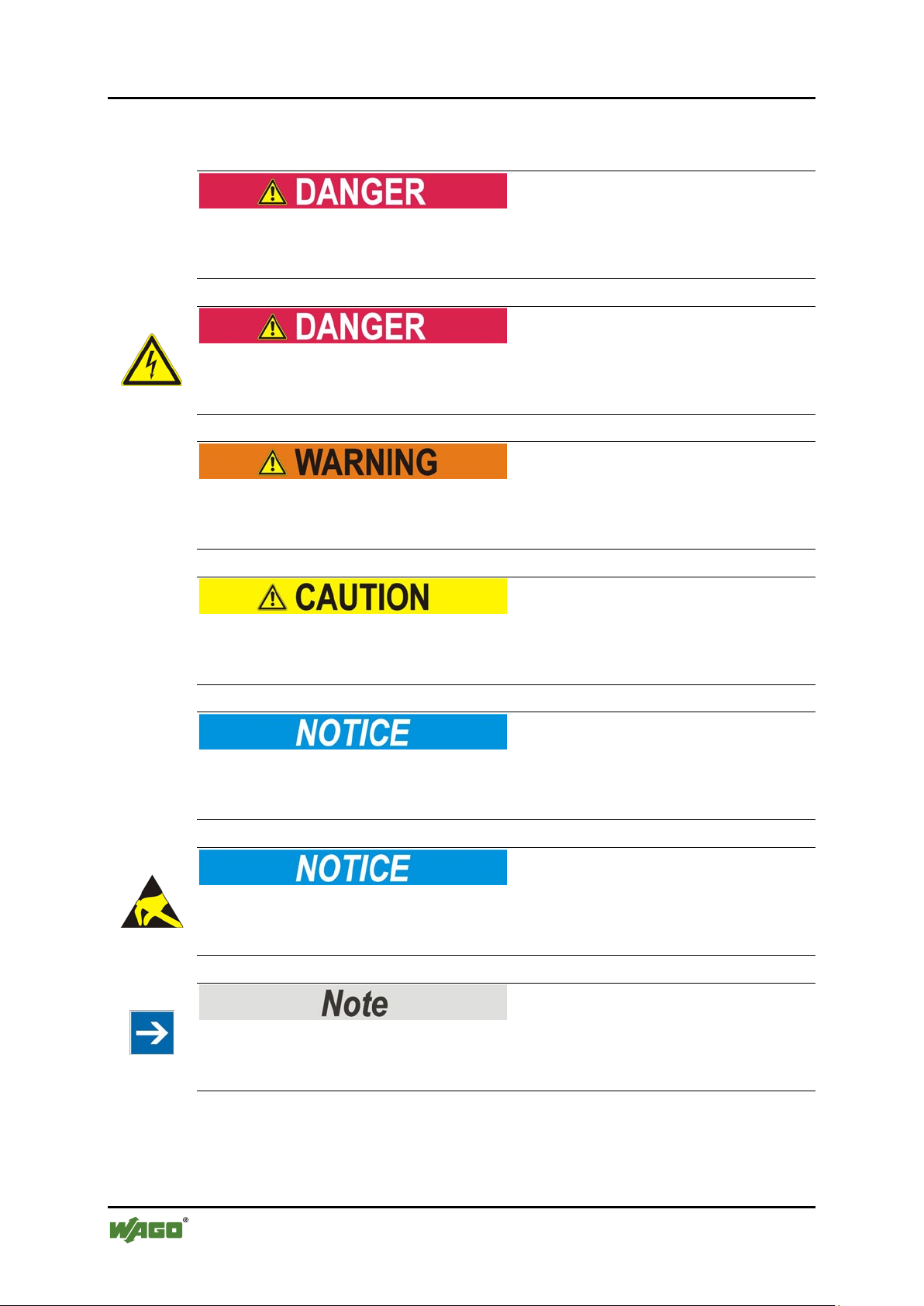
Personal Injury!
Indicates a high-risk, imminently hazardous situation which, if not avoided, will
result in death or serious injury.
Pos: 12.5.2 /All e Serie n (All gemei ne Mod ule)/ Sicher heits- und sonsti ge Hin weise/ Gefahr /Gef ahr: _ Warnu ng vor Per sonen schä den dur ch ele ktrisc hen Stro m_ - Erläuterung @ 13\mod_1343309694914_21.docx @ 101030 @ @ 1
Personal Injury Caused by Electric Current!
Indicates a high-risk, imminently hazardous situation which, if not avoided, will
result in death or serious injury.
Pos: 12.5.3 /All e Serie n (All gemei ne Mod ule)/ Sicher heits- und sons ti ge Hi n weis e/W arn ung/ War nung : _ Warn ung vor Perso nensc häde n allgem ein_ - Erläuterung @ 13\mod_1343309877041_21.docx @ 101035 @ @ 1
Personal Injury!
Indicates a moderate-risk, potentially hazardous situation which, if not avoided,
could result in death or serious injury.
Pos: 12.5.4 /All e Serie n (All gemei ne Mod ule)/ Sicher heits- und sonsti ge Hin weise/ Vorsic ht/V orsich t: _War nung v or Pers onens chäd en allge mein _ - Erläuterung @ 13\mod_1343310028762_21.docx @ 101038 @ @ 1
Personal Injury!
Indicates a low-risk, potentially hazardous situation which, if not avoided, may
result in minor or moderate injury.
Pos: 12.5.5 /All e Serie n (All gemei ne Mod ule)/ Sicher heits- und sons ti ge Hi n weis e/Ac htu ng/ Ach tung : _ War nung vor Sac hsc häd en al lg emei n_ - Erläuterung @ 13\mod_1343310134623_21.docx @ 101041 @ @ 1
Damage to Property!
Indicates a potentially hazardous situation which, if not avoided, may result in
damage to property.
Pos: 12.5.6 /All e Serie n ( All ge meine Mo dul e)/ Sich erh eits- und sonsti ge Hin weise/ Achtu ng/Ac htung : _War nung vor Sachsc häden durc h elektr ostatis che Au fladu ng_ - Erl äuter ung @ 13\ mod_1343310227702_21.docx @ 101044 @ @ 1
Damage to Property Caused by Electrostatic Discharge (ESD)!
Indicates a potentially hazardous situation which, if not avoided, may result in
damage to property.
Pos: 12.5.7 /All e Serie n (All gemei ne Mod ule)/ Sicher heits- und sonstige Hinweise/Hinweis/Hinweis: _Wichtiger Hinweis allgemein_ - Erläuterung @ 13\mod_1343310326906_21.docx @ 101047 @ @ 1
Important Note!
Indicates a potential malfunction which, if not avoided, however, will not result in
damage to property.
Pos: 12.5.8 /All e Serie n (All gemei ne Mod ule)/ Sicher heits- und sons ti ge Hi n weis e/Inf or mati on/I nf orma tio n: _ Wei ter e Inf or mati on allg emei n_ - Erl äuter ung @ 13 \mod_1343310439814_21.docx @ 101051 @ @ 1
Manual
Version 1.2.0
Page 7

WAGO-I/O-SYSTEM 750 XTR Notes about this Documentation 7
750-559/040-000 4AO 0-10V DC /XTR
Additional Information:
Refers to additional information which is not an integral part of this
documentation (e.g., the Internet).
Pos: 12.6 /Dokumentation allgemein/Gliederungselemente/---Seitenwechsel--- @ 3\mod_1221108045078_0.docx @ 21810 @ @ 1
Manual
Version 1.2.0
Page 8
8 Notes about this Documentation WAGO-I/O-SYSTEM 750 XTR
Table 1: Number Notation
Number Code
Example
Note
Decimal
100
Normal notation
Hexadecimal
0x64
C notation
Binary
'100'
'0110.0100'
In quotation marks, nibble separated with
dots (.)
Table 2: Font Conventions
Font Type
Indicates
italic
Names of paths and data files are marked in italic-type.
e.g.: C:\Program Files\WAGO Software
Menu
Menu items are marked in bold letters.
e.g.: Save
>
A greater-than sign between two names means the selection of a
e.g.: File > New
Input
Designation of input or optional fields are marked in bold letters,
e.g.: Start of measurement range
“Value”
Input or selective values are marked in inverted commas.
e.g.: Enter the value “4 mA” under Start of measurement range.
[Button]
Pushbuttons in dialog boxes are marked with bold letters in square
e.g.: [Input]
[Key]
Keys are marked with bold letters in square brackets.
e.g.: [F5]
750-559/040-000 4AO 0-10V DC /XTR
Pos: 12.7 /Al l e Ser ien ( Al lge mei ne M od ule)/Ü ber sc hrift e n/Eb ene 2/D arst ell ung der Z a hle nsys tem e - Ü bers chri ft 2 @ 23\mod_1435647128078_21.docx @ 184811 @ 2 @ 1
1.4 Number Notation
Pos: 12.8 /Al l e Ser ien ( Al lge mei ne M od ule)/R ec htli ches , Al lg emei nes /Za hle nsy st eme @ 3\mod_1221059454015_21.docx @ 21711 @ @ 1
Pos: 12.9 /Al l e Ser ien ( Al lge mei ne M od ule)/Ü ber sc hrift e n/Eb ene 2/Sc hr ift kon venti one n - Ü bersc hr ift 2 @ 23\ mod_1435647186005_21.docx @ 18 481 4 @ 2 @ 1
1.5 Font Conventions
Pos: 12.10 / All e S erie n (Al lge mei ne M o dule) /Re cht lich es, All ge mein es/ Schr ift kon venti on en @ 3\mod_1221059521437_21.docx @ 21714 @ @ 1
Pos: 13 /Dokum entati on allg emei n/Gli ederung sele mente /---Seit enwe chs el--- @ 3\mod_1221108045078_0. docx @ 2 181 0 @ @ 1
menu item from a menu.
brackets.
Manual
Version 1.2.0
Page 9

WAGO-I/O-SYSTEM 750 XTR Important Notes 9
750-559/040-000 4AO 0-10V DC /XTR
Pos: 14 /All e S eri en ( Allg emei n e Mod ule) /Ü ber schri fte n/N eue Ü b ersc hrif te n/Eb ene 1Wic hti ge Erlä ut erung en - Üb ersc hrif t 1 @ 4 \mod_1241428899156_21.docx @ 32170 @ 1 @ 1
2 Important Notes
Pos: 15.1 /Al l e Ser ien ( Al lge mei ne M od ule)/R ec htli ches , Al lg emei nes Wic htig e E rlä uter ung en - Einl eitung @ 3\mod_1221059818031_21.docx @ 21717 @ @ 1
This section includes an overall summary of the most important safety
requirements and notes that are mentioned in each individual section. To protect
your health and prevent damage to devices as well, it is imperative to read and
carefully follow the safety guidelines.
Pos: 15.2 /Al l e Ser ien ( Al lge mei ne M od ule)/Ü ber sc hrift e n/N eue Ü ber schr if ten/ Ebe ne 2R ec htli che Gru ndl age n - Ü bers chri ft 2 @ 3\mo d_1221060626343_21.docx @ 21726 @ 2 @ 1
2.1 Legal Bases
Pos: 15.3 /Al l e Ser ien ( Al lge mei ne M od ule)/R ec htli ches , Al lg emei nes Ä nderu ngs vor beh alt - Ü b erschr if t 3 und I n halt @ 3 \mod_1221060036484_21.docx @ 21720 @ 3 @ 1
2.1.1 Subject to Changes
WAGO Kontakttechnik GmbH & Co. KG reserves the right to provide for any
alterations or modifications that serve to increase the efficiency of technical
progress. WAGO Kontakttechnik GmbH & Co. KG owns all rights arising from
the granting of patents or from the legal protection of utility patents. Third-party
products are always mentioned without any reference to patent rights. Thus, the
existence of such rights cannot be excluded.
Pos: 15.4 /Serie 750 (WAGO-I/O-S YSTEM )/Wi chtig e Erlä uteru ngen/ Person alqu alifi kationPersonalqualifikation 750-xxxx - Überschrift 3 und Inh alt @ 3\mod_1224061208046_21.docx @ 24063 @ 3 @ 1
2.1.2 Personnel Qualifications
All sequences implemented on WAGO-I/O-SYSTEM 750 devices may only be
carried out by electrical specialists with sufficient knowledge in automation. The
specialists must be familiar with the current norms and guidelines for the devices
and automated environments.
All changes to the coupler or controller should always be carried out by qualified
personnel with sufficient skills in PLC programming.
Pos: 15.5 /Serie 750 (WAGO-I/O-SYSTEM)/Wichtige Erläuterungen/Bestimmungsgemäße VerwendungBestimmungsgemäße Verwendung 750-xxxx - Überschrift 3 und I nhal t @ 3\ mod_1224064151234_21.doc x @ 24070 @ 3 @ 1
2.1.3 Use of the WAGO-I/O-SYSTEM 750 in Compliance with Underlying Provisions
Fieldbus couplers, fieldbus controllers and I/O modules found in the modular
WAGO-I/O-SYSTEM 750 receive digital and analog signals from sensors and
transmit them to actuators or higher-level control systems. Using programmable
controllers, the signals can also be (pre-) processed.
The devices have been developed for use in an environment that meets the IP20
protection class criteria. Protection against finger injury and solid impurities up to
12.5 mm diameter is assured; protection against water damage is not ensured.
Unless otherwise specified, operation of the devices in wet and dusty
environments is prohibited.
Operating the WAGO-I/O-SYSTEM 750 devices in home applications without
further measures is only permitted if they meet the emission limits (emissions of
interference) according to EN 61000-6-3. You will find the relevant information
in the section “Device Description” > “Standards and Guidelines” in the manual
for the used fieldbus coupler/controller.
Manual
Version 1.2.0
Page 10

10 Important Notes WAGO-I/O-SYSTEM 750 XTR
750-559/040-000 4AO 0-10V DC /XTR
Appropriate housing (per 2014/34/EU) is required when operating the WAGOI/O-SYSTEM 750 in hazardous environments. Please note that a prototype test
certificate must be obtained that confirms the correct installation of the system in
a housing or switch cabinet.
Pos: 15.6 /Al l e Ser ien ( Al lge mei ne M od ule)/R ec htli ches , Al lg emei nes Tec hnis ch er Z ust and der Ger äte - Üb ersc hrift 3 u nd Inhalt @ 3\mod_1221060446109_21.docx @ 21723 @ 3 @ 1
2.1.4 Technical Condition of Specified Devices
The devices to be supplied ex works are equipped with hardware and software
configurations, which meet the individual application requirements. WAGO
Kontakttechnik GmbH & Co. KG will be exempted from any liability in case of
changes in hardware or software as well as to non-compliant usage of devices.
Please send your request for modified and new hardware or software
configurations directly to WAGO Kontakttechnik GmbH & Co. KG.
Pos: 15.7 /Dokumentation allgemein/Glieder ungselemente/---Seitenwechsel--- @ 3\mod_1221108045078_0.docx @ 21810 @ @ 1
Manual
Version 1.2.0
Page 11
WAGO-I/O-SYSTEM 750 XTR Important Notes 11
750-559/040-000 4AO 0-10V DC /XTR
Pos: 15.8 /Al l e Ser ien ( Al lge mei ne M od ule)/Ü ber sc hrift e n/N eue Ü ber schr if ten/ Ebe ne 2 Sich er heits hi nweis e - Ü b erschr if t 2 @ 6 \mod_1260180299987_21.docx @ 46724 @ 2 @ 1
2.2 Safety Advice (Precautions)
Pos: 15.9 /Al l e Ser ien ( Al lge mei ne M od ule)/ Sic herh eits - u nd s ons tig e Hi nweis e/ Einl eit ung Sic herh eits hin wei se H ar dwar e @ 6\mod_1260180170493_21.docx @ 46720 @ @ 1
For installing and operating purposes of the relevant device to your system the
following safety precautions shall be observed:
Pos: 15.10. 1 /A lle Ser ien ( All ge mein e D oku ment e) ( Allg em ein e M odul e)/ Wich tig e Er lä uter ung en/Si ch erh eits hin weis e/G efahr /G ef ahr: Nic ht an G erät en unter Sp ann ung ar beit en! @ 6\ mod_1260180365327_21.docx @ 46727 @ @ 1
Do not work on devices while energized!
All power sources to the device shall be switched off prior to performing any
installation, repair or maintenance work.
Pos: 15.10. 2 /S eri e 75 0 ( WAG O-I/O- SYST EM) /Wic htig e Er l äuter ung en /Sic her hei ts- und s onst ige H i nwei se/ Gef ahr/ Gefa hr: Ei nbau 07 50- xxxx nur in Geh äusen, Schrä nken oder ele ktrisc hen Betr iebsr äumen! @ 6\mod_1260180556692_21.docx @ 46731 @ @ 1
Install the device only in appropriate housings, cabinets or in electrical
operation rooms!
The WAGO-I/O-SYSTEM 750 and its components are an open system. As such,
install the system and its components exclusively in appropriate housings,
cabinets or in electrical operation rooms. Allow access to such equipment and
fixtures to authorized, qualified staff only by means of specific keys or tools.
Pos: 15.10. 3 /A lle Ser ien ( All ge mein e D oku ment e) ( Allg em ein e M odul e)/ Wich tig e Er lä uter ung en/Si ch erh eits hin weis e/G efahr /G ef ahr: Un fall verh üt ungs vors chr ift en b each te n! @ 6\mod_1260180657000_21.docx @ 46735 @ @ 1
Pos: 15.10. 4 /A lle Ser ien ( All ge mein e D oku ment e) ( Allg em ein e M odul e)/ Wich tig e Er lä uter ung en/Si ch erh eits hin weis e/G efahr /G ef ahr: Auf nor mg erec hte n Ans chl uss ac hten! @ 6\mod_1260180753479_21.docx @ 46739 @ @ 1
Pos: 15.11 / All e S erie n (Al lge mei ne M o dule) /Sic h erhei ts- und sons tige Hi nwei s e/Vor sic ht/ Vorsi cht : H eiße O berfl äc he al lge mei n @ 6\mod_1264428115588_21.docx @ 48610 @ @ 1
Hot surface!
The surface of the housing can become hot during operation. If the device was
operated at high ambient temperatures, allow it to cool off before touching it.
Pos: 15.12. 1 /A lle Ser ien ( All ge mein e D oku ment e) ( Allg em ein e M odul e)/ Wich tig e Er lä uter ung en/Si ch erh eits hin weis e/Ac ht ung/Ac htu ng: Defe kte od er besch ädigt e Gerät e austa usch en! @ 6\mod_1260180857358_21.docx @ 46743 @ @ 1
Replace defective or damaged devices!
Replace defective or damaged device/module (e.g., in the event of deformed
contacts), since the long-term functionality of device/module involved can no
longer be ensured.
Pos: 15.12.2 /Alle Serien (Allgemeine Dokumente) (Allgemeine Module)/Wich tige Er läuter ungen /Sic herh eitshi nweise /Acht ung/ Achtu ng: Ger äte vor krieche nden u nd isoli ere nden Sto ffen sch ütze n! @ 6\mod_1260181036216_21.docx @ 46747 @ @ 1
Protect the components against materials having seeping and insulating
properties!
The components are not resistant to materials having seeping and insulating
properties such as: aerosols, silicones and triglycerides (found in some hand
creams). If you cannot exclude that such materials will appear in the component
environment, then install the components in an enclosure being resistant to the
above-mentioned materials. Clean tools and materials are imperative for handling
devices/modules.
Pos: 15.12. 3 /A lle Ser ien ( All ge mein e D oku ment e) ( Allg em ein e M odul e)/ Wich tig e Er lä uter ung en/Si ch erh eits hin weis e/Ac ht ung /Ac htu ng: R eini gu ng n ur mit z ul ässig en M at eri alie n! @ 6\mod_1260181203293_21.docx @ 46751 @ @ 1
Manual
Version 1.2.0
Page 12
12 Important Notes WAGO-I/O-SYSTEM 750 XTR
750-559/040-000 4AO 0-10V DC /XTR
Clean only with permitted materials!
Clean soiled contacts using oil-free compressed air or with ethyl alcohol and
leather cloths.
Pos: 15.12. 4 /A lle Ser ien ( All ge mein e D oku ment e) ( Allg em ein e M odul e)/ Wich tig e Er lä uter ung en/Si ch erh eits hin weis e/Ac ht ung /Ac htu ng: K ei n Ko nta ktspr ay ver wend en! @ 6\mod_1260181290808_21.docx @ 46755 @ @ 1
Do not use any contact spray!
Do not use any contact spray. The spray may impair contact area functionality in
connection with contamination.
Pos: 15.12. 5 /A lle Ser ien ( All ge mein e D oku ment e) ( Allg em ein e M odul e)/ Wich tig e Er lä uter ung en/Si ch erh eits hin weis e/Ac ht ung /Ac htu ng: V erp ol ung ver meide n! @ 6\ mod_1260184045744_21.docx @ 46767 @ @ 1
Do not reverse the polarity of connection lines!
Avoid reverse polarity of data and power supply lines, as this may damage the
devices involved.
Pos: 15.12. 6 /A lle Ser ien ( All ge mein e D oku ment e) ( Allg em ein e M odul e)/ Wich tig e Er lä uter ung en/Si ch erh eits hin weis e/Ac ht ung /Ac htu ng: El ektros tatisc he Entl adu ng verm eiden! @ 6\mod_1260181364729_21.docx @ 46759 @ @ 1
Avoid electrostatic discharge!
The devices are equipped with electronic components that may be destroyed by
electrostatic discharge when touched. Please observe the safety precautions
against electrostatic discharge per DIN EN 61340-5-1/-3. When handling the
devices, please ensure that environmental factors (personnel, work space and
packaging) are properly grounded.
Pos: 15.13 / Ser ie 750 ( WA GO-I/ O-SY STEM )/ Wichti g e Erl äu ter ung en/Si cher hei ts- und s o nstig e H inw eise /Ac htu ng/Ac ht ung: XTR - Is ola tio ns prüf ung en mit DC d urch führ en! @ 15\mod_1370843209441_21.docx @ 122210 @ @ 1
Perform insulation tests with direct current (DC)!
Both the supply voltage and control voltage side are capacitively coupled to the
DIN rail. If the modules are mounted on the DIN rail, application of an AC
voltage between the two potentials can lead to the destruction of the device.
Use only direct current (DC) for insulation testing.
To avoid destroying the device, discharge the device completely before applying
the test voltage again.
Pos: 16 /Alle Seri en (Al lge mei ne Mo dul e)/ Sich er heits- und s onst ige H i nweis e/ Acht ung/ Ac htung : Ni cht in Tel ek ommu ni kati ons netz en eins etze n! (Zus atz RJ- 45) @ 3\ mod_1224065187468_21.docx @ 24076 @ @ 1
Do not use in telecommunication circuits!
Only use devices equipped with ETHERNET or RJ-45 connectors in LANs.
Never connect these devices with telecommunication networks.
Pos: 17 /Dokum entati on allg emei n/Gli ederung sele mente /---Seit enwe chs el--- @ 3\mod_1221108045078_0.docx @ 21810 @ @ 1
Manual
Version 1.2.0
Page 13
WAGO-I/O-SYSTEM 750 XTR Device Description 13
750-559/040-000 4AO 0-10V DC /XTR
Pos: 18 /Alle Seri en (Al lge mei ne Mo dul e)/Ü b erschr if ten/ Neu e Ü ber schri ft en/ Ebe ne 1 Ger äteb esc hrei bung - Ü ber schr if t 1 @ 3\mod_1233756084656_21.docx @ 27096 @ 1 @ 1
3 Device Description
Pos: 19.1 /Serie 750 (WAGO-I/O-SYSTEM)/Gerätebeschreibung/Einleitung/Anwendung/AO/Anwendung 750- 05xx AO (0...10V) @ 5\mod_1247046851995_21.docx @ 36817 @ @ 1
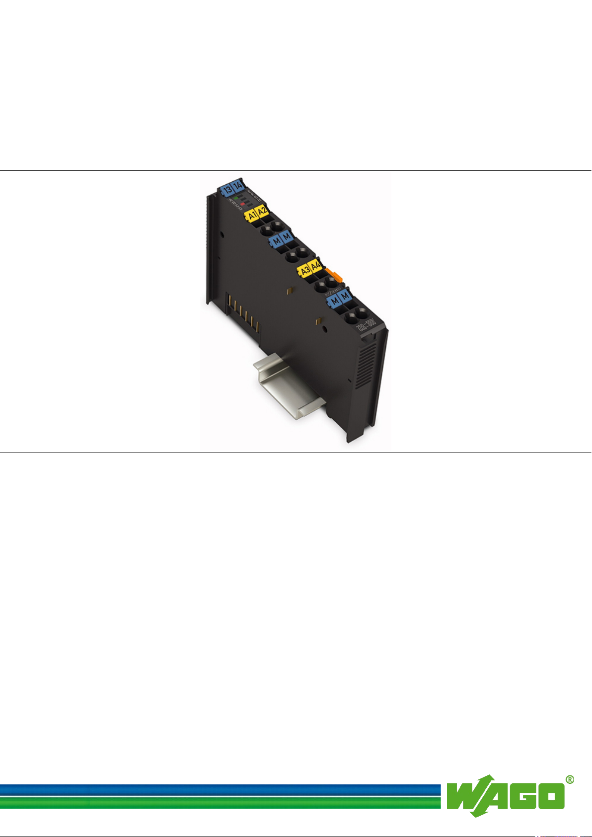
The analog output module 750-559/040-000 (4AO 0-10V DC /XTR) generates a
standardized signal of 0 … 10 V for the field area.
Pos: 19.2 /Serie 750 (WAGO-I/O-S YST EM)/ Ger äteb esc hrei bung /Ei nlei tung /I/ O-Besc hrei bu ng/ AO/I/ O-Beschreibung 750-05xx 4 AO 2-Leiter (AO1.. .AO4 u nd Mass e) @ 5\mod_1247053300854_21.docx @ 36880 @ @ 1
The I/O module has 4 output channels, making direct wiring of four 2-wire
actuators possible.
The actuators are connected to CAGE CLAMP® connectors AO 1 and common
Pos: 19.3 /Serie 750 (WAGO-I/O-S YST EM)/ Ger äteb esc hrei bung /Ei nlei tung /I/ O-Besc hrei bu ng/ AO/I/ O-Beschreibung 750-05xx AO Gemei nsam es M ass epo tent ial @ 5 \mod_1247050255026_21.docx @ 36870 @ @ 1
Pos: 19.4 /Serie 750 (WAGO-I/O-S YST EM)/ Ger äteb esc hrei bung /Ei nlei tung /I/ O-Besc hr eibu ng/ All gem ein/ Ver weis auf K apit el " Ansc hl üsse" @ 8\mod_1276775378035_21.docx @ 57956 @ @ 1
Pos: 19.5 /Serie 750 (WAGO-I/O-S YST EM)/ Ger äteb esc hrei bung /Ei nlei tung /I/ O-Besc hr eibu ng/ All gem ein/ Ver weis auf K apit el " Ger äte ans chli eß en" > "Ansc hlussb eispi el(e)" @ 5\mod_1246015203281_21.docx @ 36298 @ @ 1
Pos: 19.6 /Serie 750 (WAGO-I/O-S YST EM)/ Ger äteb esc hrei bung /Ei nlei tung /LED -Anz eig e/LE D Z ust and B etrie b und Kle mmen bus-Ko mmuni katio n @ 5\mod_1247054901573_21.docx @ 36892 @ @ 1
Pos: 19.7 /Serie 750 (WAGO-I/O-S YST EM)/ Ger äteb esc hrei bung /Einl ei tung /LED- Anz eig e/LED Fe hl er K urzsc hl uss/ Über la st @ 5\ mod_1247118146009_21.docx @ 36939 @ @ 1
Pos: 19.8 /Serie 750 (WAGO-I/O-S YST EM)/ Geräte bes chr eibu ng/Ei nlei tu ng/L ED-A nzeig e/Ver weis au f Kapit el "Anz eige elemen te" @ 5\mod_1246010525000_21.docx @ 36194 @ @ 1
Pos: 19.9 /Serie 750 (WAGO-I/O-S YST EM)/ Ger äteb esc hrei bung /Ei nleitung/Versorgung/Spannungsversorgung aus Systemspannung @ 5\mod_1247116433759_21.docx @ 36920 @ @ 1
Pos: 19.10 / Ser ie 750 ( WA GO-I/ O-SY STEM )/G erät ebe schr eibu ng/E inl eitung /V ersor gu ng/V ers orgung 24 V, 0 V über Leist ungs konta kte Stan dard @ 3\ mod_1226498974531_21.docx @ 25020 @ @ 1
Pos: 19.11 / Ser ie 750 ( WA GO-I/ O-SY STEM )/ Wichti g e Erl äu ter ung en/Si cher hei ts- und s ons tig e Hi nw eise /Acht u ng/Ac ht ung: Ma xim aler Str om Leis tung s konta kte 10 A @ 3\mod_1226499143500_21.docx @ 25029 @ @ 1
(ground) or AO 2, AO 3, AO 4 and respective common (ground).
The channels have a common ground potential.
The assignment of the connections is described in the “Connectors” section.
Connection examples are shown in section “Connecting Devices” > … >
“Connection Example(s)”.
The operational readiness and the trouble-free internal data bus communication of
the channels are indicated via a green function LED.
A red error LED indicates a short circuit or overcurrent.
The meaning of the LEDs is described in the “Display Elements” section.
Power to the internal electronics is supplied via internal data bus.
The I/O module 750-559/040-000 (4AO 0-10V DC /XTR) receives the 24 V
voltage supply for the field level from an upstream I/O module or from the
fieldbus coupler/controller via blade-formed power jumper contacts. It then
provides these potentials to subsequent I/O modules via spring-formed power
jumper contacts.
Do not exceed maximum current via power jumper contacts!
The maximum current to flow through the power jumper contacts is 10 A.
Greater currents can damage the contacts.
When configuring your system, ensure that this current is not exceeded. If
exceeded, insert an additional supply module.
Pos: 19.12 / Ser ie 750 ( WA GO-I/ O-SY STEM )/ Wichti g e Erl äu ter ung en/Si cher hei ts- und sonstige Hinweise/Hinweis/Hinweis: Potenti al eins peis e klem me f ür E rde eins etz en! (k eine LK f ür E rde) @ 3\mod_1226499037468_21.docx @ 25023 @ @ 1
Use supply modules for ground (earth)!
The I/O module has no power jumper contacts for receiving and transmitting the
earth potential. Use a supply module when an earth potential is needed for the
subsequent I/O modules.
Pos: 19.13 / Ser ie 750 ( WA GO-I/ O-SYSTEM)/Gerätebeschreibung/Einleitung/Funktion/Galvanische Trennung Ausgangssignal/Systemebene (12 Bit) @ 5\mod_1247050641729_21.docx @ 36877 @ @ 1
The Output signal is electrically isolated and will be transmitted with a resolution
of 12 bits.
Pos: 19.14 / Ser ie 750 ( WA GO-I/ O-SY STEM )/ Wichti g e Erl äu ter ung en/Si cher hei ts- und sonstige Hinweise/Hinweis/Hinweis: XTR - Mischbetrieb XTR/Hinweis: XTR - Misch betri eb XTR/ Stan dard @ 15\mod_1367496420828_21.docx @ 118326 @ @ 1
Manual
Version 1.2.0
Page 14
14 Device Description WAGO-I/O-SYSTEM 750 XTR
750-559/040-000 4AO 0-10V DC /XTR
Mixed operation
Mixed operation (standard/XTR modules) within a node is possible when groups
of modules are electrically isolated on the field side (i.e., electrically isolated
power supply).
Pos: 19.15 /S eri e 7 50 ( WAG O-I/O- SYST EM) /Wi chtig e Er l äuter ung en /Sic her hei ts- und so nstige Hinweise/Hinweis/Hinweis: XTR - Erhöht e St örf estig k eit @ 15\ mod_1367496424993_21.docx @ 118330 @ @ 1
Increased interference!
For standard-compliant application in substation instrumentation and control,
telecontrol systems, railway technology or shipbuilding certified operation,
field-side power supply filter 750-624/040-001 or power supply filter
750-626/040-000 are generally to be used for XTR module groups.
Pos: 19.16 / Ser ie 750 ( WA GO-I/ O-SY STEM) /Gerät ebes chrei bung /Einlei tung/ Eins atzb ereich/ Eins atzb ereich 7 50-xxxx/ 040-000 al le XTR-K oppl er /Ei nsat zber ei ch 7 50- xxxx/040-00 0 al le XT R- Koppl er/- Contr oller ohne Ei nschr änku ng @ 15\mod_1368425919479_21.docx @ 119444 @ @ 1
The I/O module can be operated with all fieldbus couplers/controllers of the
WAGO-I/O-SYSTEM 750 XTR.
Observe the instructions for mixed operation when used in mixed operation
behind standard fieldbus couplers/controllers.
Pos: 20 /Dokum entati on allg emei n/Gli ederung sele mente /---Seit enwe chs el--- @ 3\mod_1221108045078_0.docx @ 21810 @ @ 1
Manual
Version 1.2.0
Page 15
WAGO-I/O-SYSTEM 750 XTR Device Description 15
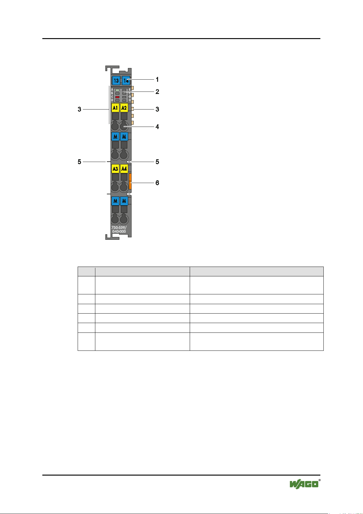
Table 3: Legend for Figure “View”
Pos.
Description
Details See Section
1
Marking possibility with MiniWSB
--2
Status LEDs
“Device Description” > “Display Elements”
3
Data contacts
“Device Description” > “Connectors”
4
CAGE CLAMP® connectors
“Device Description” > “Connectors”
5
Power jumper contacts
“Device Description” > “Connectors”
6
Release tab
“Mounting” > “Inserting and Removing
Devices”
750-559/040-000 4AO 0-10V DC /XTR
Pos: 21.1 /Al l e Ser ien ( Al lge mei ne M od ule)/Ü ber sc hrift e n/N eue Ü ber schr if ten/ Ebe ne 2 Ans ich t - Ü bersc hri ft 2 @ 4\mod_1240984217343_21.docx @ 31958 @ 2 @ 1
3.1 View
Pos: 21.2 /Serie 750 (WAGO-I/O-S YSTEM )/Ger äteb eschr eibu ng/Ans icht /Anal ogausg angs klem men/A nsicht 750-05 59/ 040- xxx @ 17\mod_1380708771349_21.docx @ 133580 @ @ 1
Figure 1: View
Pos: 21.3 /Serie 750 (WAGO-I/O-S YST EM) /Ger äte bes chr ei bung /Ans ic ht/A nsic ht C ag eCl amp® _Leg en de mit LEDs , mi t 1 Entr ieg el ung slasc h e @ 1 5\mod_1370867188922_21.docx @ 122225 @ @ 1
Pos: 21.4 /Dokumentation allgemein/Glieder ungselemente/---Seitenwechsel--- @ 3\mod_1221108045078_0.docx @ 21810 @ @ 1
Manual
Version 1.2.0
Page 16
16 Device Description WAGO-I/O-SYSTEM 750 XTR
750-559/040-000 4AO 0-10V DC /XTR
Pos: 21.5 /All e Serien ( Allg emei ne Mo dule) /Ü bers chri ft en/N eu e Üb ersc hrif te n/Eb ene 2An schl üss e - Ü ber schr if t 2 @ 4\mod_1240984262656_21.docx @ 31961 @ 2 @ 1
3.2 Connectors
Pos: 21.6 /Serie 750 (WAGO-I/O-S YST EM)/ Ger äteb esc hrei bung /Ans chl üsse /Da ten konta kt e/Kl emme nbus - Ü berschr ift 3 @ 6\ mod_1256294684083_21.docx @ 43660 @ 3 @ 1
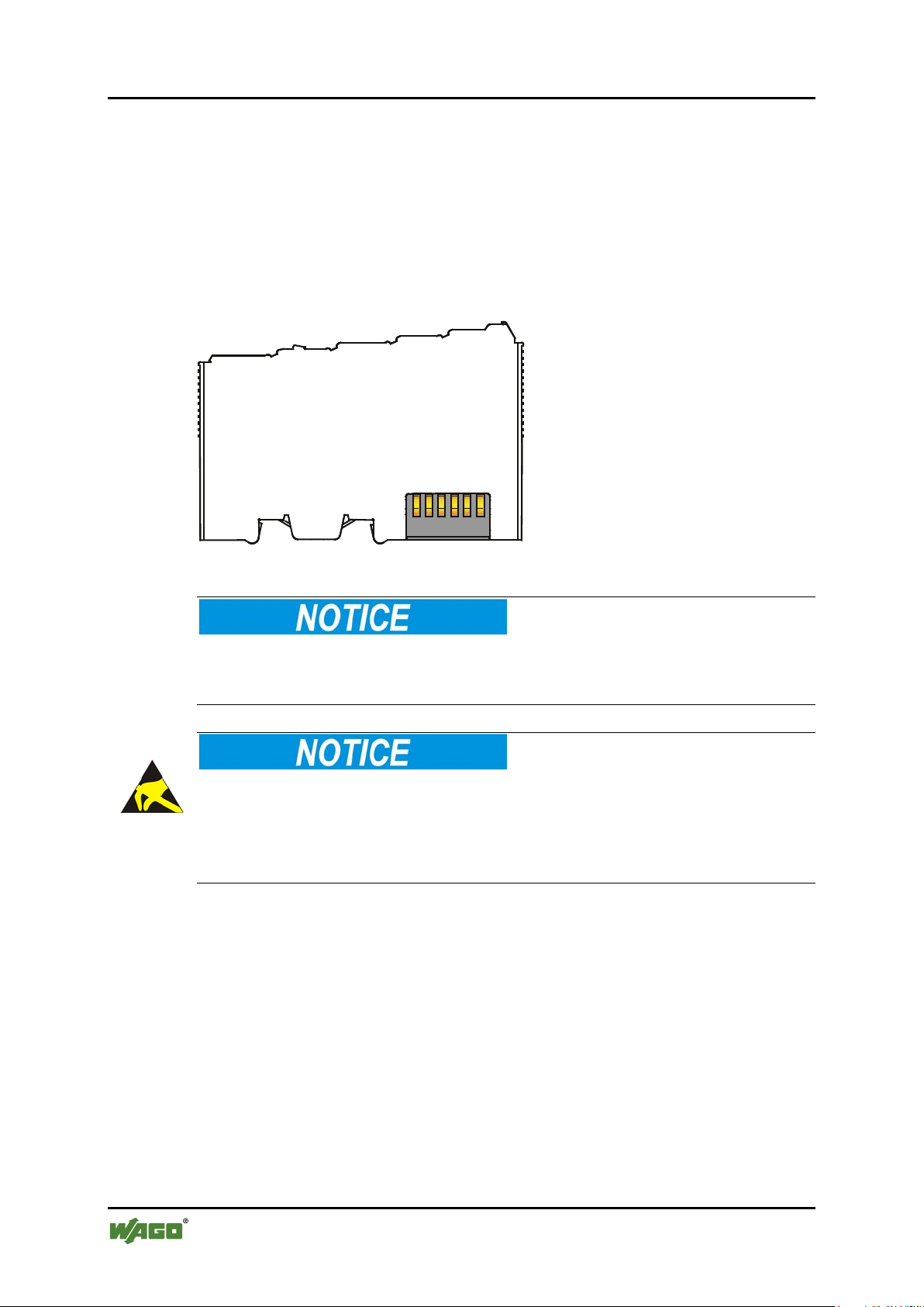
3.2.1 Data Contacts/Internal Bus
Pos: 21.7.1 /S erie 750 (W AGO- I/O-SYSTEM)/Gerätebeschreibung/Anschlüsse/Datenkontakte - Feldbuskoppler /-con trol ler , A bbil dung u nd B esc hrei bu ng @ 3\mod_1231771259187_21.docx @ 26002 @ @ 1
Communication between the fieldbus coupler/controller and the I/O modules as
well as the system supply of the I/O modules is carried out via the internal bus. It
is comprised of 6 data contacts, which are available as self-cleaning gold spring
contacts.
Figure 2: Data Contacts
Pos: 21.7.2 /S erie 750 (W AGO- I/O-SYSTEM)/Wichtige Erläuterungen/Sicherheits- und sonstig e H in weis e/A chtu ng/ Ach tung : Buskl em men nic ht a uf G oldf eder k onta kte leg en! @ 7 \mod_1266318463636_21.docx @ 50695 @ @ 1
Do not place the I/O modules on the gold spring contacts!
Do not place the I/O modules on the gold spring contacts in order to avoid soiling
or scratching!
Pos: 21.7.3 /S erie 750 (W AGO-I/ O-SYSTEM)/Wichtige Erläuterungen/Sicherheits- und sonstige Hinweise/Achtung/Achtung: ESD - A uf gut e Erdung der Umg ebung achte n! @ 7\mod_1266318538667_21.docx @ 50708 @ @ 1
Ensure that the environment is well grounded!
The devices are equipped with electronic components that may be destroyed by
electrostatic discharge. When handling the devices, ensure that the environment
(persons, workplace and packing) is well grounded. Avoid touching conductive
components, e.g. data contacts.
Pos: 21.8 /Dokumentation allgemein/Glieder ungselemente/---Seitenwechsel--- @ 3\mod_1221108045078_0.docx @ 21810 @ @ 1
Manual
Version 1.2.0
Page 17

WAGO-I/O-SYSTEM 750 XTR Device Description 17
Table 4: Legend for Figure “Power Jumper Contacts”
Contact
Type
Function
1
Spring contact
Potential transmission (Uv) for field supply
2
Spring contact
Potential transmission (0 V) for field supply
3
Blade contact
Potential feed-in (0 V) for field supply
4
Blade contact
Potential feed-in (Uv) for field supply
750-559/040-000 4AO 0-10V DC /XTR
Pos: 21.9 /Serie 750 (WAGO-I/O-S YST EM)/ Ger äteb esc hrei bung /Ans chl üsse /Lei stu ngs kont akt e/Fel dver sor gu ng - Üb ersc hri ft 3 @ 6\mod_1256294692864_21.docx @ 43664 @ 3 @ 1
3.2.2 Power Jumper Contacts/Field Supply
Pos: 21.10. 1 /S eri e 75 0 ( WAG O-I/O- SYST EM) /Wic htig e Er l äuter ung en /Sic her hei ts- und s onst ige H i nwei se/ Vors ich t/V orsic ht: V erlet zu ngsg efa hr d urc h sc har fka ntig e Mes ser kon ta kte! @ 6\mod_1256193279401_21.docx @ 43414 @ @ 1
Risk of injury due to sharp-edged blade contacts!
The blade contacts are sharp-edged. Handle the I/O module carefully to prevent
injury.
Pos: 21.10. 2 /S eri e 75 0 ( WAG O-I/O- SYST EM) /G erät ebe schr eib ung/ Ans chl üss e/L eist ungs kon ta kte 2 LK ( M ess er/L eist ung s konta kte 2 LK (M esser /F eder ) - Einl eitu ng @ 15\ mod_1371721641099_21.docx @ 123714 @ @ 1
The I/O module 750-559/040-000 has 2 self-cleaning power jumper contacts that
supply and transmit power for the field side. The contacts on the left side of the
I/O module are designed as blade contacts and those on the right side as spring
contacts.
Pos: 21.10. 3 /S eri e 75 0 ( WAG O-I/O- SYST EM) /Ger äte bes chr eib ung/ Ans chl üss e/L eist ungs kon tak te 2 LK ( M ess er/L eist ung sko nta kte 2 LK (Mes ser /F eder ) - Abbil dung , ei nf ache Br eite - St an dard @ 1 5\mod_1367500700037_21.docx @ 118396 @ @ 1
Figure 3: Power Jumper Contacts
Pos: 21.10. 4 /S eri e 75 0 ( WAG O-I/O- SYST EM) /G erät ebe schr eib ung/ Ans chl üss e/L eist ungs kon ta kte 2 LK ( M ess er/L eist ung s konta kte 2 LK (M esser /F eder ) - Leg end e @ 1 5\mod_1371721352500_21.docx @ 123710 @ @ 1
Pos: 21.10. 5 /S eri e 75 0 ( WAG O-I/O- SYST EM) /Wic htig e Er l äuter ung en /Sic her hei ts- und s onst ige H i nwei se/ Acht ung /Ac htung : Maxi maler Stro m Leistu ngsko ntak te 10 A @ 3\mod_1226499143500_21.docx @ 25029 @ @ 1
Do not exceed maximum current via power jumper contacts!
The maximum current to flow through the power jumper contacts is 10 A.
Greater currents can damage the contacts.
When configuring your system, ensure that this current is not exceeded. If
exceeded, insert an additional supply module.
Pos: 21.10. 6 /S eri e 75 0 ( WAG O-I/O- SYST EM) /Wic htig e Er l äuter ung en /Sic her hei ts- und s onst ige H i nwei se/ Hin weis /Hi nwei s: P ot enti alei nsp eis ekl emm e für Er de eins etz en! (kei ne LK f ür Er de) @ 3\mod_1226499037468_21.docx @ 25023 @ @ 1
Manual
Version 1.2.0
Page 18

18 Device Description WAGO-I/O-SYSTEM 750 XTR
750-559/040-000 4AO 0-10V DC /XTR
Use supply modules for ground (earth)!
The I/O module has no power jumper contacts for receiving and transmitting the
earth potential. Use a supply module when an earth potential is needed for the
subsequent I/O modules.
Pos: 21.11 /D o kum entat io n all ge mei n/Gli ed eru ngsel e ment e/---Sei ten wec hsel --- @ 3\mod_1221108045078_0.docx @ 21810 @ @ 1
Manual
Version 1.2.0
Page 19

WAGO-I/O-SYSTEM 750 XTR Device Description 19
Table 5: Legend for Figure “CAGE CLAMP® Connectors”
Channel
Designation
Connector
Function
AO 1
1
Analog output 1: Signal voltage
Common
(ground)
Analog output 1: Common (ground)
AO 2
5
Analog output 2: Signal voltage
Common
(ground)
Analog output 2: Common (ground)
AO 3
3
Analog output 3: Signal voltage
Common
(ground)
Analog output 3: Common (ground)
AO 4
7
Analog output 4: Signal voltage
Common
(ground)
Analog output 4: Common (ground)
750-559/040-000 4AO 0-10V DC /XTR
Pos: 21.12 / Ser ie 750 ( WA GO-I/ O-SY STEM )/G erät ebe schr ei bu ng/A nsc hlüss e/C AG E C LAM P-Anschlü sse - Über schr ift 3 @ 6\mod_1256296337770_21.docx @ 43674 @ 3 @ 1
3.2.3 CAGE CLAMP® Connectors
Pos: 21.13 / Ser ie 750 ( WA GO-I/ O-SY STEM )/G erät ebe schr ei bu ng/A nsc hlüss e/ Anal og ausg ang s klemm en/A nsc hlüs se 750- 055 7, -0559 @ 14\mod_1359705332140_21.docx @ 110715 @ @ 1
Figure 4: CAGE CLAMP
®
Connectors
1
2
3
4
Pos: 21.14 / Ser ie 750 ( WA GO-I/ O-SY STEM )/ Wichti g e Erl äu ter ung en/Si cher hei ts- und s o nstig e H inw eise /Hi nwei s/Hi n weis : Ges chi r mte Sig nal lei tu nge n ver we nde n! @ 7\mod_1265723251019_21.docx @ 50140 @ @ 1
Use shielded signal lines!
Only use shielded signal lines for analog signals and I/O modules which are
equipped with shield clamps. Only then can you ensure that the accuracy and
interference immunity specified for the respective I/O module can be achieved
even in the presence of interference acting on the signal cable.
2
6
4
8
Pos: 21.15 / Ser ie 750 ( WA GO-I/ O-SY STEM )/A nsc hli eße n/Ver wei s a uf K api tel Sc hirm ung im S yst emh and buc h XTR @ 19\ mod_1399554643119_21.docx @ 153199 @ @ 1
For further information about shielding, see system manual WAGO-I/O-SYSTEM
750 XTR, section “Connect Devices” > … > “Shielding.”
Pos: 21.16 /D o kum entat io n all ge mei n/Gli ed eru ngsel e ment e/---Sei ten wec hsel --- @ 3\mod_1221108045078_0.docx @ 21810 @ @ 1
Manual
Version 1.2.0
Page 20

20 Device Description WAGO-I/O-SYSTEM 750 XTR
Table 6: Legend for Figure “Display Elements”
Designation
LED
State
Function
No operational readiness or the internal data bus
communication is interrupted
Operational readiness and trouble-free internal
data bus communication
Off
No error
Overload or short circuit to ground in one of the
output channels
750-559/040-000 4AO 0-10V DC /XTR
Pos: 21.17 / Alle S erie n (Al lge mei ne M odul e) /Üb ersc hri ften /Ne ue Ü ber sc hrift e n/Eb ene 2Anz eig eel em ente - Üb erschr ift 2 @ 4\mod_1240984390875_21.docx @ 31964 @ 2 @ 1
3.3 Display Elements
Pos: 21.18 / Ser ie 750 ( WA GO-I/ O-SY STEM )/G erät ebe schr eibu ng/A nzeig eel e mente/ An alog ausgang skl emme n/Anzei geel eme nte 750-05xx/040-xxx 4AO ( Agn, Cr t) @ 17\ mod_1380641377218_21.docx @ 133466 @ @ 1
Figure 5: Display Elements
Function
A
Error C
Pos: 21.19 / All e S erie n (Al lge mei ne M o dule) /Üb ersc hri ft en/N eu e Über sc hrif te n/Eb ene 2Be die nel ement e - Über schr ift 2 @ 4\mod_1239191655456_21.docx @ 30439 @ 2 @ 1
3.4 Operating Elements
Pos: 21.20 / Ser ie 750 ( WA GO-I/ O-SYST EM) /Ger ätebe schr ei bu ng/B edi enel eme nte/ Be dien ele men te B us kle mme 7 50- xxxx nicht vorhanden @ 4\mod_1236322031125_21.docx @ 28063 @ @ 1
The I/O module 750-559/040-000 has no operating elements.
Pos: 21.21 /D o kum entat io n all ge mei n/Gli ed eru ngsel e ment e/---Sei ten wec hsel --- @ 3\mod_1221108045078_0.docx @ 21810 @ @ 1
Off
Green
Red
Manual
Version 1.2.0
Page 21

WAGO-I/O-SYSTEM 750 XTR Device Description 21
750-559/040-000 4AO 0-10V DC /XTR
Pos: 21.22 / All e S erie n (Al lge mei ne M o dule) /Üb ersc hri ft en/N eu e Über sc hrif te n/Eb ene 2Sc he matis ches Sc hal tbi ld - Ü ber schr if t 2 @ 4\mod_1240984441312_21.docx @ 31967 @ 2 @ 1
3.5 Schematic Diagram
Pos: 21.23 / Ser ie 750 ( WA GO-I/ O-SY STEM) /Gerät ebes chrei bung /Sche matis che Sc haltbil der/ Analog ausg angs klem men/Sc hemati sch es Schalt bild 750-055 9/04 0-xxx @ 17\mod_1380712534380_21.docx @ 133611 @ @ 1
Figure 6: Schematic Diagram
Pos: 21.24 /D o kum entat io n all ge mei n/Gli eder ung sel ement e/---S eiten wec hsel --- @ 3\mod_1221108045078_0.docx @ 21810 @ @ 1
Manual
Version 1.2.0
Page 22

22 Device Description WAGO-I/O-SYSTEM 750 XTR
Table 7: Technical Data – Device
Width
12 mm
Height (from upper edge of DIN 35 rail)
61 mm
Length
100 mm
Weight
53.5 g
Degree of protection
IP20
Table 8: Technical Data – Supply
Current consumption, system voltage
max.
(5 VDC)
125 mA
Current consumption, power jumper
contact
typ.
(24 VDC)
---
Voltage via power jumper contacts:
under laboratory conditions
+55 °C … +70 °C
24 VDC
Current via power jumper contacts
max.
10 A
Rated surge voltage
1 kV
1)
Including residual ripple of 15 %
Table 9: Technical Data – Communication
Bit width
4 × 16 bits data
4 × 8 bits control/status (optional)
750-559/040-000 4AO 0-10V DC /XTR
Pos: 21.25 / All e S erie n (Al lge mei ne M o dule) /Üb ersc hri ft en/N eu e Über sc hrif te n/Eb ene 2T echni sc he Da te n - Üb ers chrif t 2 @ 3 \mod_1232967587687_21.docx @ 26924 @ 2 @ 1
3.6 Technical Data
Pos: 21.26. 1 /S eri e 75 0 ( WAG O-I/O- SYST EM) /G erät ebe schr eib ung/ Tec hni sch e D ate n/VS ( Var i ablen ste uer ung )/Tec h nisch e D ate n Ger ät ( VS) - XT R @ 15\ mod_1369311215011_21.doc x @ 120260 @ 3 @ 1
3.6.1 Device
Pos: 21.26. 2 /S eri e 75 0 ( WAG O-I/O- SYST EM) /Ger äte besc hrei bung /Tec h nisch e D ate n/V S (V ari abl enste uer ung )/T ech nisc he D at en Vers org ung ( VS) D C 24 V - XT R @ 15\ mod_1369311347965_21.docx @ 120278 @ 3 @ 1
3.6.2 Supply
for ambient operating temperature
for ambient operating temperature
Pos: 21.26. 3 /S eri e 75 0 ( WAG O-I/O- SYST EM) /Ger äte besc hrei bung /Tec hni sch e Dat en/V S ( Vari abl en steu eru ng) /Tec hni sch e Dat e n Ko mmuni kat ion (V S) @ 4\mod_1242119312796_21.docx @ 32970 @ 3 @ 1
3.6.3 Communication
+15 °C … +35 °C
−40 °C … +55 °C
18 V … 31.2 V (17.4 V … 31.2 V) 1)
18 V … 28.8 V (17.4 V … 28.8 V) 1)
18 V … 26.4 V (17.4 V … 26.4 V) 1)
Pos: 21.26.4 /S erie 75 0 (WAG O-I/O-SY ST EM) /Ger äte bes chr eibung / Tec hnis che D at en/A n alog ausg ang skl em men/T ec hnisc h e Dat en 7 50- 055 9/Tec hnis ch e D aten 75 0-0 559/ 040- xxx @ 17\mod_1380710481106_21.docx @ 133603 @ 3 @ 1
Manual
Version 1.2.0
Page 23

WAGO-I/O-SYSTEM 750 XTR Device Description 23
Table 10: Technical Data – Outputs
No. of outputs
4
Load impedance
> 5 kΩ
Signal voltage
0 V … 10 V
Resolution
12 bit
Conversion time
typ.
10 ms
Recovery time
typ.
100 ms
Measuring error at 25 °C
< ±0.1 % of upper range value
Temperature coefficient
< ±0.01 %/K of upper range value
Table 11: Technical Data – Field Wiring
Wire connection
CAGE CLAMP®
Cross section
0.25 mm² … 2.5 mm² / AWG 24 … 14
Stripped lengths
8 mm … 9 mm / 0.33 in
Table 12: Technical Data – Power Jumper Contacts
Power jumper contacts
blade/spring contact, self-cleaning, hard
gold plated
Voltage drop at I
max.
< 1 V at 64 I/O modules
Table 13: Technical Data – Data Contacts
Data contacts
slide contact, self-cleaning, hard gold
plated
Table 14: Technical Data – Mechanical Conditions
Vibration resistance
Max. 5g 1)
1)
Follow the installation instructions
Table 15: Technical Data – Climatic Environmental Conditions
Operating temperature range
−40 °C … +70 °C
Storage temperature range
−40 °C … +85 °C
Relative humidity
1)
95 %
Elevation above sea level
max.
5000 m
1)
Short-term condensation per Class 3K7/IEC EN 60721-3-3 and E DIN 40046-721-3 (except
wind-driven precipitation, water and ice formation)
750-559/040-000 4AO 0-10V DC /XTR
3.6.4 Outputs
Pos: 21.26. 5 /S eri e 75 0 ( WAG O-I/O- SYST EM) /G erät ebe schr eib ung/ Tec hni sch e D ate n/VS ( Var i ablen ste uer ung )/Tec h nisch e D ate n Ans chl uss tec hni k (V S) @ 1 6\mod_1373273824961_21.docx @ 125714 @ 3 @ 1
3.6.5 Connection Type
Pos: 21.26. 6 /S eri e 75 0 ( WAG O-I/O- SYST EM) /G erät ebe schr eib ung/ Tec hni sch e D ate n/VS ( Var i ablen ste uer ung )/Tec h nisch e D ate n M echa nisc he Bedi ng ung en ( VS) - XTR @ 1 5\mod_1369387569701_21.docx @ 120364 @ 3 @ 1
3.6.6 Mechanical Conditions
Pos: 21.26. 7 /S eri e 75 0 ( WAG O-I/O- SYST EM) /G erät ebe schr eib ung/ Tec hni sch e D ate n/VS ( Var i ablen ste uer ung )/Tec h nisch e D ate n kli ma tisc he Umw elt bedi ngu nge n (V S) - X TR @ 15\mod_1369387559187_21.docx @ 120360 @ 3 @ 1
3.6.7 Climatic Environmental Conditions
without temperature derating
with temperature derating
Pos: 21.27 /D o kum entat io n all gem ei n/Gli eder ungs ele ment e/---Sei ten wec hsel --- @ 3\mod_1221108045078_0.docx @ 21810 @ @ 1
Manual
Version 1.2.0
0 m … 2000 m
2000 m … 5000 m: 0.5 K per 100 m
Page 24

24 Device Description WAGO-I/O-SYSTEM 750 XTR
Conformity Marking
CULUS
ANSI/ISA 12.12.01
Class I, Div2 ABCD T4
IECEx
750-559/040-000 4AO 0-10V DC /XTR
Pos: 21.28 / All e S erie n (Al lge mei ne M o dule) /Üb ersc hri ft en/N eu e Über sc hrif te n/Eb ene 2Z ulass ung en - Über schr ift 2 @ 3\mod_1224055364109_21.docx @ 24030 @ 2 @ 1
3.7 Approvals
Pos: 21.29. 1 /S eri e 75 0 ( WAG O-I/O- SYST EM) /G erät ebe schr eib ung/ Zul ass ung en/ Infor m ati on: Weit ere I nf ormat io nen z u Z ula ssu nge n 7 50-xxxx @ 3\mod_1227190967156_21.docx @ 25221 @ @ 1
More information about approvals.
Detailed references to the approvals are listed in the document “Overview
Approvals WAGO-I/O-SYSTEM 750”, which you can find via the internet
under: www.wago.com > SERVICES > DOWNLOADS > Additional
documentation and information on automation products > WAGO-I/O-SYSTEM
750 > System Description.
Pos: 21.29. 2 /S eri e 75 0 ( WAGO-I/O-S YSTEM )/Ger ätebe schr eibung /Zul assung en/A llge mein/Z ulass unge n Buskle mme 7 50-xxxx Allgemein, ohne Variantenangabe - Einleitung @ 4 \mod_1237460656921_21.docx @ 28643 @ @ 1
The following approvals have been granted to 750-559/040-000 I/O modules:
Pos: 21.29. 3 /A lle Ser ien ( All ge mein e M odul e)/ Zul ass ung en/S tan dar dzul ass ung en/C E ( Kon for mit ätsk ennz eic hnu ng) @ 3\ mod_1224494777421_21.docx @ 24276 @ @ 1
Pos: 21.29. 4 /A lle Ser ien ( All ge mein e M odul e)/ Zul ass ung en/S tan dar dzul ass ung en/c ULus ( UL50 8) @ 3\ mod_1224055013140_0.docx @ 24020 @ @ 1
Pos: 21.29. 5 /A lle Ser ien ( All ge mein e M odul e)/ Zul ass ung en/S tan dar dzul ass ung enKC - K ore a C ertifi c ate - A O @ 20\mod_1406533092951_21.docx @ 160372 @ @ 1
Pos: 21.29. 6 /D ok ument ati on al lg em ein/G li eder ung sel eme nte/------Le erzei le------ @ 3\ mod_1224662755687_0.docx @ 24460 @ @ 1
Pos: 21.29. 7 /S eri e 75 0 ( WAG O-I/O- SYST EM) /G erät ebe schr eib ung/ Zul ass ung en/ Ex/Z ul ass ung en B uskl emm e 7 50-xxxx Ex, ohne Variantenangabe - Einleitung @ 4\ mod_1237191218000_21.docx @ 28423 @ @ 1
The following Ex approvals have been granted to 750-559/040-000 I/O modules:
Pos: 21.29. 8 /A lle Ser ien ( All ge mein e M odul e)/Z ulas su nge n/Ex-Z ul ass unge n/cU Lus/ cU Lus ( AN SI/I SA 12. 12.0 1) C las s I, Di v2 A BCD T4 @ 3\ mod_1224054791812_0.docx @ 24014 @ @ 1
Pos: 21.29. 9 /D ok ument ati on al lg em ein/G li eder ung sel eme nte/------Le erzei le------ @ 3\ mod_1224662755687_0.docx @ 24460 @ @ 1
Pos: 21.29. 10 / Seri e 7 50 ( WA GO-I /O-SY STEM) /Ger ät ebesc hrei bu ng/Z ulas sung en/ Ex/Z ul. i n Vor bereit ung Bus klem me 750- xxxx Ex, ohne Variantenangabe - Einleitung @ 7\mod_1274259264803_21.docx @ 56610 @ @ 1
The following Ex approvals are pending for 750-559/040-000 I/O modules:
Pos: 21.29. 11.1 / Alle Seri en (All ge mein e M odul e)/Z ulas sung en/ Ex-Zulassungen/Sonstige/ATEX allgemein @ 16\mod_1373352135578_0.docx @ 125803 @ @ 1
Pos: 21.29. 11.2 / Alle Seri en (All ge mein e M odul e)/Z ul ass unge n/E x-Z ulass ung en/I ECE x ( TÜV Nor d)/ IEC Ex al lge mei n @ 16\ mod_1373353532946_0.docx @ 125807 @ @ 1
Pos: 21.29.12 /Dok ument ation all gem ein/Gli eder ungsel eme nte/------Leer zeil e------ @ 3\mod_1224662755687_0.docx @ 24460 @ @ 1
Pos: 21.29. 13 / Seri e 7 50 ( WA GO-I /O-SY STEM)/ Gerät ebesc hrei bung/Z ulas sunge n/Schi ff/ Einlei tungss ätzeZ ulas sung en Buskl emm e 750-xxxx Sc hiff , ohn e Var iant ena nga be - Einl eit ung @ 4\ mod_1237190918453_21.docx @ 28420 @ @ 1
The following ship approvals have been granted to 750-559/040-000 I/O modules:
Pos: 21.29. 14 / All e Ser ien (Al lg emei ne M od ule)/ Zul ass ung en/ Schi ffs zul ass ung en/G L (G er mani sc her Ll o yd) C at. A, B, C , D ( EMC 1) , H @ 15 \mod_1370521488638_0.docx @ 122022 @ @ 1
CULUS
UL508
Korea Certification MSIP-REM-W43-AOM750
ATEX
Pos: 21.29.15 /Dok ument ation all gem ein/Gli eder ungsel eme nte/------Leer zeil e------ @ 3\mod_1224662755687_0.docx @ 24460 @ @ 1
Pos: 21.29. 16 / Seri e 7 50 ( WA GO-I /O-SY STEM) /G erät eb esc hrei bung /Z ulas sung en/ Schi ff/ Einl ei tung ss ätzeZ ul . i n Vor ber eitu ng Bus kle mme 7 50- xxx x Sc hiff , oh ne V ari ant ena nga be - Ei nl eitu ng @ 7\ mod_1274259318897_21.docx @ 56614 @ @ 1
Pos: 21.29. 17.1 / Alle Seri en (All ge mein e D okum ent e) ( Allg em ein e M odule) /Z ul ass unge n/Sc hiffs zul ass ung en /ABS (A meri ca n Bur ea u of Shi ppi ng) @ 3\mod_1224055151062_0.docx @ 24023 @ @ 1
Pos: 21.29. 17.2 / Alle Seri en (All ge mein e D okum ent e) ( Allg em ein e M odule) /Z ul ass unge n/Sc hiffs zul ass ung en /BSH (B und esa mt f ür S eesc hif ff ahrt und Hy drog raphi e) @ 5 \mod_1246341825156_21.docx @ 36334 @ @ 1
Manual
Version 1.2.0
GL (Germanischer Lloyd) Cat. A, B, C, D (EMC 1), H
The following ship approvals are pending for 750-559/040-000 I/O modules:
ABS (American Bureau of Shipping)
Page 25

WAGO-I/O-SYSTEM 750 XTR Device Description 25
750-559/040-000 4AO 0-10V DC /XTR
Federal Maritime and Hydrographic Agency
Pos: 21.29. 17.3 / Alle Seri en (All ge mein e D okum ent e) ( Allg em ein e M odule) /Z ul ass unge n/Sc hiffs zul ass ung en /BV ( Bur ea u Ver it as) @ 3\ mod_1224492116171_0.docx @ 24220 @ @ 1
BV (Bureau Veritas)
Pos: 21.29. 17.4 / Alle Seri en (All ge mein e D okum ent e) ( Allg em ein e M odule) /Z ul ass unge n/Sc hiffs zul ass ung en /DNV (D et N ors ke Verit as) Cl ass B @ 3\mod_1224492540562_0.docx @ 24224 @ @ 1
DNV (Det Norske Veritas) Class B
Pos: 21.29.17 .5 /All e Seri en (Allg em eine D o kume nte) (Al lge mei ne M od ule)/Z ul ass ung en/ Schi ffs zul ass ung en/KR ( Kor ean R egi st er of Shi ppi ng) @ 3\ mod_1224492806109_0.docx @ 24232 @ @ 1
KR (Korean Register of Shipping)
Pos: 21.29. 17.6 / Alle Seri en (All ge mein e D okum ent e) ( Allg em ein e M odule) /Z ul ass unge n/Sc hiffs zul ass ung en /LR (Llo yd’s R egis ter ) E nv. 1, 2, 3, 4 @ 3\ mod_1224492890453_0.docx @ 24236 @ @ 1
LR (Lloyd’s Register) Env. 1, 2, 3, 4
Pos: 21.29. 17.7 /Al le Seri en ( Allg em ein e D okum ent e) ( Allg em ein e Mod ule) /Z ulas sung en/ Sc hiffs zul ass ung en/ NKK (Ni pp on K aiji Kyo kai) @ 3\mod_1224493002656_0.docx @ 24240 @ @ 1
NKK (Nippon Kaiji Kyokai)
Pos: 21.29. 17.8 / Alle Seri en (All ge mein e D okum ent e) ( Allg em ein e M odule) /Z ul ass unge n/Sc hiffs zul ass ung en /PR S (P ols ki R eje str Sta tk ów) @ 3\mod_1224497273250_0.docx @ 24295 @ @ 1
PRS (Polski Rejestr Statków)
Pos: 21.29. 17.9 / Alle Seri en (All ge mein e D okum ent e) ( Allg em ein e M odule) /Z ul ass unge n/Sc hiffs zul ass ung en /RIN A ( Regi str o I tali ano N a vale) @ 3\mod_1224493078359_0.docx @ 24244 @ @ 1
RINA (Registro Italiano Navale)
Pos: 21.29.17.10 /Dokumentation allgemei n/Gli eder ungsel emen te/------Leerz eile------ @ 3 \mod_1224662755687_0.docx @ 24460 @ @ 1
Pos: 21.29.18 /Dok ument ation all gem ein/Gli eder ungsel eme nte/---Sei ten wech sel--- @ 3\mod_1221108045078_0.docx @ 21810 @ @ 1
Manual
Version 1.2.0
Page 26

26 Device Description WAGO-I/O-SYSTEM 750 XTR
Table 16: Climatic and Mechanical Environmental Conditions
Standard
Test Value
Transport
EN 60870-2-2
Ct2(2k4) (except precipitation / water /
moisture)
Mechanical Environmental Conditions
EN 60870-2-2
Bm
EN 60721-3-1
1M3
EN 60721-3-3
3M5
EN 60068-2-6
Acceleration 5g
IEC 60068-2-27 Shock
15g, 11 ms, 1000 shocks per axis and
direction, half-sine
25g, 6 ms, 1000 shocks per axis and direction,
half-sine
EN 50155
Random vibration:
Category 1, classes A and B
Shock 5g, 30 ms:
Category 1, classes A and B
Shipbuilding*)
Ambient categories A … D, H
(5g, 25 Hz … 150 Hz)
Climatic Environmental Conditions
EN 60721-3-1
1K5 (except precipitation and ice formation)
EN 60721-3-3
3K7 (except wind-driven precipitation, water
and ice formation)
EN 60870-2-2
C3 (except wind-driven precipitation and ice
formation)
Shipbuilding*)
Ambient categories A … D, H
(−40 °C … +70 °C)
*)
The list of ship certifications issued is available in the section “Approvals”.
750-559/040-000 4AO 0-10V DC /XTR
Pos: 21.30 / All e S erie n (Al lge mei ne M o dule) /Üb ersc hri ft en/N eu e Über sc hrif te n/Eb ene 2N orme n un d Ri chtl ini en - Über schri ft 2 @ 4\mod_1242804031875_21.docx @ 33646 @ 2 @ 1
3.8 Standards and Guidelines
Pos: 21.31. 1 /S eri e 75 0 ( WAG O-I/O- SYST EM) /G erät ebe schr eib ung/N or me n u nd Ri cht lini en/N or men und Richtl inien B uskle mme 750- xxxx, ohne Variantenangabe - Einleitung @ 7\mod_1274278887584_21.docx @ 56645 @ @ 1
750-559/040-000 I/O modules meet the following standards and guidelines:
Pos: 21.31. 2 /S eri e 75 0 ( WAG O-I/O- SYST EM)/G erät ebesc hreib ung/N orme n und Ric htlini en/N ormen u nd Rich tlinie n XTR - Mechanik und Klima Komponenten-HB @ 18\mod_1394633219581_21.docx @ 147751 @ @ 1
EN 61373
Pos: 21.31. 3 /D ok ument ati on al lg em ein/G li eder ung sel eme nte/---S eit enwec hs el--- @ 3\ mod_1221108045078_0.docx @ 21810 @ @ 1
Manual
Version 1.2.0
Page 27

WAGO-I/O-SYSTEM 750 XTR Device Description 27
Table 17: EMC – Immunity to Interference
Standard
Test Value
Electrostatic Discharge
• EN 61000-4-2
• IEEE C37.90.3
8 kV (contact discharge)
High-frequency Electromagnetic Fields
• EN 61000-4-3 + A1: + A2
• IEEE C37.90.2
20 V/m (80 MHz … 1 GHz)
Fast Electrical Transient Disturbances / Burst
• EN 61000-4-4
• IEEE C37.90.1
4 kV
Surge Voltage / Surge
• EN 61000-4-5
• EN 60255-22-5
1 kV (conductor/conductor)
2 kV (conductor/ground)
Conducted Disturbances, Induced by High-frequency Fields
• EN 61000-4-6
• EN 60255-22-6
10 V (150 kHz … 80 MHz)
Magnetic Fields With Electrical Frequencies
• EN 61000-4-8
300 A/m continuous / 1000 A/m for 1 s
Pulse-shaped Magnetic Fields
• EN 61000-4-9 + A1
300 A/m
Damped Oscillatory Magnetic Fields
• EN 61000-4-10 + A1
100 A/m
Voltage Dips, Short-term Interruptions and Voltage Fluctuations
• EN 61000-4-11
Standard not applicable
Damped Sinusoidal Oscillations
• EN 61000-4-12
1 kV (conductor/conductor)
2 kV (conductor/ground)
Harmonics and Interharmonics
• EN 61000-4-13 + A1
Standard not applicable
Conducted Asymmetric Disturbances
• EN 61000-4-16 + A1 + A2
30 V continuous
300 V for 1 s
Line Frequency Disturbances
• EN 60255-22-7
Standard not applicable
Alternating Components of the Voltage to DC Line Connections
• EN 61000-4-17+A2
15 %
750-559/040-000 4AO 0-10V DC /XTR
Pos: 21.31. 4 /S eri e 75 0 ( WAG O-I/O- SYST EM) /G erät ebe schr eib ung/N or me n u nd Ri cht lini en/ EMV-N or men C on trol ler 75 0-xxxx/EMV-N orm en Buskl emm e 750-xxxx/004 0-0000 , nur St andard versi on - Ei nleitung XTR @ 18 \mod_1395909426189_21.docx @ 149708 @ @ 1
The I/O module 750-559/040-000 meets the following EMC standards as these
Pos: 21.31. 5 /S eri e 75 0 ( WAG O-I/O- SYST EM) /G erät ebe schr eib ung/N or me n u nd Ri cht lini en/N or men Stör fes tig kei t XTR @ 18\mod_1394030613258_21.docx @ 147348 @ @ 1
standards relate to the I/O module:
• EN 60255-22-2
• EN 60255-22-3
• EN 60255-22-4
8 kV (air discharge)
10 V/m (1 GHz … 3 GHz)
Manual
Version 1.2.0
Page 28

28 Device Description WAGO-I/O-SYSTEM 750 XTR
Table 17: EMC – Immunity to Interference
Standard
Test Value
Damped Oscillatory Waves
• EN 61000-4-18 + A1
• IEEE C37.90.1
1.25 kV conductor/conductor
Voltage Dips, Short-term Interruptions and Voltage Fluctuations to DC Supply
Inputs
• EN 61000-4-29
• EN 60255-11
Standard not applicable
Harmonics
• Shipbuilding*)
Standard not applicable
*)
The list of ship certifications issued is available in the section “Approvals”.
Table 18: EMC – Emission of Interference
Standard
Test Value *)
Enclosure Emission of Interference
• EN 61000-6-3 + A1
30 dB(µV/m), QP, 30 MHz … 230 MHz
54 dB(µV/m), AV, 3 GHz … 6 GHz
• EN 61000-6-4 + A1
40 dB(µV/m), QP, 30 MHz … 230 MHz
60 dB(µV/m), AV, 3 GHz … 6 GHz
• Shipbuilding
**)
(EMC 1)
80 dB(µV/m) …50 dB(µV/m), QP,
24 dB(µV/m), QP, 156 MHz … 165 MHz
• Shipbuilding
**)
(EMC 2)
80 dB(µV/m) … 50 dB(µV/m), QP,
24 dB(µV/m), QP, 156 MHz … 165 MHz
750-559/040-000 4AO 0-10V DC /XTR
• EN 60255-22-1
Pos: 21.31. 6 /S eri e 75 0 ( WAG O-I/O- SYST EM)/G erät ebesc hreib ung/N orme n und Rich tlini en/Nor men St öraus send ung XTR @ 18\mod_1394087664442_21.docx @ 147358 @ @ 1
• EN 55022 Class B
2.5 kV conductor/ground
37 dB(µV/m), QP, 230 MHz … 1 GHz
70 dB(µV/m), Peak, 1 GHz … 3 GHz
50 dB(µV/m), AV, 1 GHz … 3 GHz
74 dB(µV/m), Peak, 3 GHz … 6 GHz
• EN 60255-26
• EN 55011 + A1 Class A
• EN 55022 Class A
47 dB(µV/m), QP, 230 MHz … 1 GHz
76 dB(µV/m), Peak, 1 GHz … 3 GHz
56 dB(µV/m), AV, 1 GHz … 3 GHz
80 dB(µV/m), Peak, 3 GHz … 6 GHz
150 kHz … 300 kHz
50 dB(µV/m) … 34 dB(µV/m), QP,
0.3 MHz … 30 MHz
54 dB(µV/m), QP, 30 MHz … 2 GHz
150 kHz … 30 MHz
60 dB(µV/m) … 54 dB(µV/m), QP,
30 MHz … 100 MHz
54 dB(µV/m), QP, 100 MHz … 2 GHz
Manual
Version 1.2.0
Page 29

WAGO-I/O-SYSTEM 750 XTR Device Description 29
Table 18: EMC – Emission of Interference
Standard
Test Value *)
Conducted Emission of Interference – Line Connection AC Voltage
• EN 61000-6-3 + A1
• EN 55022 Class B
Standard not applicable
• EN 61000-6-4 + A1
• EN 55011 + A1 Class A
Standard not applicable
Conducted Emission of Interference – Line Connection
• Shipbuilding
**)
(EMC 1)
96 dB(µV) … 50 dB(µV), 10 kHz … 150 kHz
50 dB(µV), 0.35 MHz … 30 MHz
• Shipbuilding
**)
(EMC 2)
120 dB(µV) … 69 dB(µV),
73 dB(µV), 0.5 MHz … 30 MHz
Conducted Emission of Interference – Line Connection DC Voltage
• EN 61000-6-3 + A1
79 dB(µV) QP, 0.15 MHz … 0.5 MHz
60 dB(µV) AV, 0.5 MHz … 30 MHz
*)
QP = Quasi Peak Detector; AV = Average Detector
or EMC 2).
750-559/040-000 4AO 0-10V DC /XTR
60 dB(µV) … 50 dB(µV),
150 kHz … 350 kHz
10 kHz … 150 kHz
79 dB(µV), 150 kHz … 500 kHz
• EN 60255-26
• EN 55022 Class A
**)
If necessary, please find different data in the section “Approval” (regarding approval for EMC 1
Pos: 22 /Dokum entati on allg emei n/Gli ederung sele mente /---Seit enwe chs el--- @ 3\mod_1221108045078_0.docx @ 21810 @ @ 1
66 dB(µV) AV, 0.15 MHz … 0.5 MHz
73 dB(µV) QP, 0.5 MHz … 30 MHz
Manual
Version 1.2.0
Page 30

30 Process Image WAGO-I/O-SYSTEM 750 XTR
Table 19: Process Image
Binary
Output Value
0.00
'0000.0000.0000.0000'
0x0000 0 0x00
1.25
'0001.0000.0000.0000'
0x1000
4096
0x00
2.50
'0010.0000.0000.0000'
0x2000
8192
0x00
3.75
'0011.0000.0000.0000'
0x3000
12288
0x00
5.00
'0100.0000.0000.0000'
0x4000
16384
0x00
6.25
'0101.0000.0000.0000'
0x5000
20480
0x00
7.50
'0110.0000.0000.0000'
0x6000
24576
0x00
8.75
'0111.0000.0000.0000'
0x7000
28672
0x00
10.00
'0111.1111.1111.1111'
0x7FFF
32767
0x00
750-559/040-000 4AO 0-10V DC /XTR
Pos: 23 /All e S eri en ( Allg emei n e Mod ule) /Ü ber schri fte n/N eue Ü b ersc hrif te n/Eb ene 1Pr ozess a bbil d - Über sc hrift 1 @ 4\ mod_1240983067828_21.docx @ 31942 @ 1 @ 1
4 Process Image
Pos: 24 /Ser ie 75 0 (WA GO-I/ O-SYS TEM) /Proz essab bild Klemme nbus/ Hinw eis: Pro zessa bbil dmappi ng abh ängig von FBK/ PFC, o hne Stat us-/C ontr olb yte XT R @ 1 8\mod_1396511070508_21.docx @ 150 676 @ @ 1
Mapping of process data in the process image of fieldbus systems
The representation of the process data of some I/O modules or their variations in
the process image depends on the fieldbus coupler/controller used. Please take
this information from the section “I/O Modules” included in the description
concerning the process image of the corresponding coupler/controller.
Pos: 25 /Ser ie 75 0 (WA GO-I/ O-SYS TEM )/ Proz ess abbi ld Kle mme nbus /A nalog aus ga ngs klem me n/Pr oz essab bil d 7 50-0 559/ 040-000 @ 18\mod_1392290197027_21.docx @ 145382 @ @ 1
The analog output module 750-559/040-000 provides 16 bits of data and 8 status
bits per channel.
The digitalized output value is output in a data word (16 bit) via the process image
of the fieldbus coupler/controller as output byte 0 (low) and output byte 1 (high).
This value is mapped with a resolution of 12 bit to bit B3 … B14.
The three least significant bits (B0 … B2) are not evaluated.
With analog output module 750-559/040-000, the numerical value range of
0x0000 to 0x7FFF is scaled to the output voltage range of 0 V to 10 V.
Output Value
0 V … 10 V
Pos: 26 /Ser ie 75 0 (WA GO-I/ O-SYS TEM )/ Proz ess abbi ld Kle mme nbus /Hi nw eis: Stat us byt e-Aus wer tung ni cht mögl ic h @ 6 \mod_1256127653548_21.docx @ 43347 @ @ 1
No Status Byte to evaluate!
Some fieldbus systems can process the status information of process values using
by means of a status byte.
As the returned status byte of this I/O module is always zero, it will not be parsed.
Pos: 27 /Dokum entati on allg emei n/Gli eder ungs ele ment e/---Seit en wechs el--- @ 3\mod_1221108045078_0.docx @ 21810 @ @ 1
Numerical Value
Hex. Dec.
Status Byte
Hex.
Manual
Version 1.2.0
Page 31

WAGO-I/O-SYSTEM 750 XTR Mounting 31
750-559/040-000 4AO 0-10V DC /XTR
Pos: 28 /All e S eri en ( Allg emei n e Mod ule) /Ü ber schri fte n/N eue Ü b ersc hrif te n/Eb ene 1M onti eren - Üb ersc hrift 1 @ 3\ mod_1225446744750_21.docx @ 24900 @ 1 @ 1
5 Mounting
Pos: 29.1 /Serie 750 (WAGO-I/O-SYSTEM)/Monti eren/D emon tiere n/Mo ntager eihe nfolg e @ 3\mod_1231770210031_21.docx @ 25992 @ 2 @ 1
5.1 Mounting Sequence
Fieldbus couplers/controllers and I/O modules of the WAGO-I/O-SYSTEM
750/753 are snapped directly on a carrier rail in accordance with the European
standard EN 50022 (DIN 35).
The reliable positioning and connection is made using a tongue and groove
system. Due to the automatic locking, the individual devices are securely seated
on the rail after installation.
Starting with the fieldbus coupler/controller, the I/O modules are mounted
adjacent to each other according to the project design. Errors in the design of the
node in terms of the potential groups (connection via the power contacts) are
recognized, as the I/O modules with power contacts (blade contacts) cannot be
linked to I/O modules with fewer power contacts.
Pos: 29.2 /Serie 750 (WAGO-I/O-S YSTEM )/Wi chtig e Erlä uteru ngen/ Sicher heits- und so nstig e H inw eis e/Vor sic ht/ Vor sic ht: Verl etz ungs ge fahr dur ch s ch arf kant ige M ess er kont akt e! @ 6\mod_1256193279401_21.docx @ 43414 @ @ 1
Risk of injury due to sharp-edged blade contacts!
The blade contacts are sharp-edged. Handle the I/O module carefully to prevent
injury.
Pos: 29.3 /Serie 750 (WAGO-I/O-S YSTEM) /Wic htige Erlä uteru nge n/Si cher heit s- und sonstige Hinweise/Achtung/Achtung: Busklemmen nur in vorgesehener Reihenfolge stecken! @ 6\mod_1256194177073_21.docx @ 43429 @ @ 1
Insert I/O modules only from the proper direction!
All I/O modules feature grooves for power jumper contacts on the right side. For
some I/O modules, the grooves are closed on the top. Therefore, I/O modules
featuring a power jumper contact on the left side cannot be snapped from the top.
This mechanical coding helps to avoid configuration errors, which may destroy
the I/O modules. Therefore, insert I/O modules only from the right and from the
top.
Pos: 29.4 /Serie 750 (WAGO-I/O-S YSTEM )/Wi chtig e Erlä uteru ngen/ Sicher heits- und sonstige Hinweise/Hinweis/Hinweis: Bu sabsc hlus s XTR nic ht verg essen! @ 15\mod_1368426836647_21.docx @ 119458 @ @ 1
Don't forget the bus end module!
Always plug a bus end module 750-600/040-000 onto the end of the fieldbus
node! You must always use this bus end module at all fieldbus nodes with the
WAGO I/O System 750 XTR fieldbus couplers/controllers to guarantee proper
data transfer.
Pos: 29.5 /Serie 750 (WAGO-I/O-SYSTEM)/Montieren/Demontieren/Busklemmen 750xxxx/0040xxxx 4g-5g @ 15\mod_1367558844291_21.docx @ 118470 @ @ 1
For vibration loads > 4g, observe the following installation instructions:
• Use pan-head screws or blind rivets at least every 60 mm (12 mm pin
spacing) to secure the DIN rail.
• Make the open conductor length between strain relief and wire connection
as short as possible.
Pos: 29.6 /Dokumentation allgemein/Glieder ungselemente/---Seitenwechsel--- @ 3\mod_1221108045078_0.docx @ 21810 @ @ 1
• Use the reinforced end stop 249-197.
Manual
Version 1.2.0
Page 32

32 Mounting WAGO-I/O-SYSTEM 750 XTR
750-559/040-000 4AO 0-10V DC /XTR
Pos: 29.7 /Serie 750 (WAGO-I/O-S YST EM)/ Mon tier en/D em onti eren/ Ger äte ein füg en u nd e nt fer nen - Ü ber schr if t 2 @ 3\ mod_1231768483250_21.doc x @ 25950 @ 2 @ 1
5.2 Inserting and Removing Devices
Pos: 29.8 /Al l e Ser ien ( Al lge mei ne M od ule)/ Sic herh eits - u nd s ons tig e Hi nweis e/ Vorsi cht /V orsi cht : Hei ß e Ob erfl äch e al lge mei n @ 6 \mod_1264428115588_21.docx @ 48610 @ @ 1
Hot surface!
The surface of the housing can become hot during operation. If the device was
operated at high ambient temperatures, allow it to cool off before touching it.
Pos: 29.9 /Al l e Ser ien ( Al lge mei ne M od ule)/ Sic herh eits - u nd s ons tig e Hi nweis e/ Ac htung /Ac htu ng: Arb eit en a n Ger ät en n ur s pan nung sfr ei d urc hf ühr en! @ 6\ mod_1256193963573_21.doc x @ 43426 @ @ 1
Perform work on devices only if they are de-energized!
Working on energized devices can damage them. Therefore, turn off the power
supply before working on the devices.
Pos: 29.10 / Ser ie 750 ( WA GO-I/ O-SY STEM )/ Wichti g e Erl äu ter ung en/Si cher hei ts- und s o nstig e H inw eise /Ac htu ng/Ac ht ung: XTR nic ht unt er -2 0 °C ver draht en oder u mstec ken @ 15\ mod_1367559895186_21.docx @ 118480 @ @ 1
Observe operating temperature!
XTR I/O modules may be operated below −20 °C, but not wired and/or
reconnected.
Pos: 29.11 / Ser ie 750 ( WA GO-I/ O-SY STEM) /Monti ere n/De montier en/Bus kle mme einf ügen @ 3\mod_1231769726703_21.docx @ 25989 @ 3 @ 1
5.2.1 Inserting the I/O Module
1. Position the I/O module so that the tongue and groove joints to the fieldbus
coupler/controller or to the previous or possibly subsequent I/O module are
engaged.
Figure 7: Insert I/O Module (Example)
2. Press the I/O module into the assembly until the I/O module snaps into the
carrier rail.
Manual
Version 1.2.0
Page 33

WAGO-I/O-SYSTEM 750 XTR Mounting 33
750-559/040-000 4AO 0-10V DC /XTR
Figure 8: Snap the I/O Module into Place (Example)
With the I/O module snapped in place, the electrical connections for the data
contacts and power jumper contacts (if any) to the fieldbus coupler/controller or to
the previous or possibly subsequent I/O module are established.
Pos: 29.12 / Ser ie 750 ( WA GO-I/ O-SY STEM) /Monti ere n/De montier en/Bus kle mme ent ferne n @ 4\mod_1239169375203_21.docx @ 30334 @ 3 @ 1
5.2.2 Removing the I/O Module
1. Remove the I/O module from the assembly by pulling the release tab.
Figure 9: Removing the I/O Module (Example)
Electrical connections for data or power jumper contacts are disconnected when
removing the I/O module.
Pos: 30 /D okum ent atio n allge mein/ Glie derungs elem ente/ ---Seite nwec hsel --- @ 3\mod_1221108045078_0.docx @ 21810 @ @ 1
Manual
Version 1.2.0
Page 34

34 Connect Devices WAGO-I/O-SYSTEM 750 XTR
750-559/040-000 4AO 0-10V DC /XTR
Pos: 31 /All e S eri en ( Allg emei n e Mod ule) /Ü ber schri fte n/N eue Ü b ersc hrif te n/Eb ene 1Ger ät e an schl ieß en - Ü b erschr if t 1 @ 3 \mod_1234172889468_21.docx @ 27460 @ 1 @ 1
6 Connect Devices
Pos: 32 /Ser ie 75 0 (WA GO-I/ O-SYS TEM) /Wic htige Er läut erunge n/Si cherh eits- u nd s onsti g e Hin wei se/ Ach tung /Ac htu ng: An di e Ausg äng e kein e Sp ann ung anl eg en! @ 23\ mod_1435156239711_21.docx @ 184501 @ @ 1
Do not apply any voltage to the outputs!
Never connect the outputs to external voltage sources. Also, do not connect the
outputs to each other.
Failure to observe these measures can damage the product!
Pos: 33 /Ser ie 75 0 (WA GO-I/ O-SYS TEM )/ Ans chli eße n/L eiter a n CA GE C LAM P ansc hli eßen ( al lg emei n) - Ü bersc hrift 2 u nd Text @ 3\mod_1225448660171_21.docx @ 24928 @ 2 @ 1
6.1 Connecting a Conductor to the CAGE CLAMP®
The WAGO CAGE CLAMP® connection is appropriate for solid, stranded and
finely stranded conductors.
Only connect one conductor to each CAGE CLAMP®!
Only one conductor may be connected to each CAGE CLAMP®.
Do not connect more than one conductor at one single connection!
If more than one conductor must be routed to one connection, these must be
connected in an up-circuit wiring assembly, for example using WAGO feedthrough terminals.
1. For opening the CAGE CLAMP® insert the actuating tool into the opening
above the connection.
2. Insert the conductor into the corresponding connection opening.
3. For closing the CAGE CLAMP® simply remove the tool. The conductor is
now clamped firmly in place.
Figure 10: Connecting a Conductor to a CAGE CLAMP
Pos: 34 /Dokum entati on allg emei n/Gli ederung sele mente /---Seit enwe chs el--- @ 3\mod_1221108045078_0.docx @ 21810 @ @ 1
®
Manual
Version 1.2.0
Page 35

WAGO-I/O-SYSTEM 750 XTR Connect Devices 35
750-559/040-000 4AO 0-10V DC /XTR
Pos: 35 /All e S eri en ( Allg emei n e Mod ule) /Ü ber schri fte n/N eue Ü b ersc hrif te n/Eb ene 2An schl uss bei spi el - Übersc hrif t 2 @ 4\ mod_1242621672468_21.docx @ 33293 @ 2 @ 1
6.2 Connection Example
Pos: 36 /Ser ie 75 0 (WA GO-I/ O-SYS TEM) /Wic htige Er läut erunge n/Si cherh eits- u nd s onsti g e Hin wei se/H i nweis /Hi nw eis: Ges chir mt e Sig nal leit ung en ver wen den! @ 7 \mod_1265723251019_21.docx @ 50140 @ @ 1
Use shielded signal lines!
Only use shielded signal lines for analog signals and I/O modules which are
equipped with shield clamps. Only then can you ensure that the accuracy and
interference immunity specified for the respective I/O module can be achieved
even in the presence of interference acting on the signal cable.
Pos: 37 /Ser ie 75 0 (WA GO-I/ O-SYS TEM) /Ans chließ en/Ver weis auf Kapi tel Schirmung im Systemhandbuch XTR @ 19\mod_1399554643119_21.docx @ 153199 @ @ 1
For further information about shielding, see system manual WAGO-I/O-SYSTEM
750 XTR, section “Connect Devices” > … > “Shielding.”
Pos: 38 /Ser ie 75 0 (WA GO-I/ O-SYST EM) /Ans chli eßen/ Anschl uss beispi ele/ Analog ausg angs klemm en/Ans chlus sbeis piel 75 0-05 57, -0559 @ 14\mod_1359704874471_21.docx @ 110707 @ @ 1
Figure 11: Connecting Diagram
Pos: 39 /Dokum entati on allg emei n/Gli ederung sele mente /---Seit enwe chs el--- @ 3\mod_1221108045078_0.docx @ 21810 @ @ 1
Manual
Version 1.2.0
Page 36

36 Use in Hazardous Environments WAGO-I/O-SYSTEM 750 XTR
750-559/040-000 4AO 0-10V DC /XTR
Pos: 40.1 /Al l e Ser ien ( Al lge mei ne M od ule)/Ü ber sc hrift e n/Eb ene 1Ei nsatz i n e xpl osio nsge fähr det en B erei ch en - Über schri ft 1 @ 3\mod_1224075191281_21.docx @ 24084 @ 1 @ 1
7 Use in Hazardous Environments
Pos: 40.2 /Serie 750 (WAGO-I/O-S YST EM)/ Eins atz i n E x-Ber ei chen /Ei ns atzber ei ch S eri e 7 50 @ 3\mod_1234272230203_21.docx @ 27500 @ @ 1
The WAGO-I/O-SYSTEM 750 (electrical equipment) is designed for use in
Zone 2 hazardous areas.
The following sections include both the general identification of components
(devices) and the installation regulations to be observed. The individual
subsections of the “Installation Regulations” section must be taken into account if
the I/O module has the required approval or is subject to the range of application
of the ATEX directive.
Pos: 40.3 /Dokumentation allgemein/Glieder ungselemente/---Seitenwechsel--- @ 3\mod_1221108045078_0.docx @ 21810 @ @ 1
Manual
Version 1.2.0
Page 37

WAGO-I/O-SYSTEM 750 XTR Use in Hazardous Environments 37
750-559/040-000 4AO 0-10V DC /XTR
Pos: 40.4 /Serie 750 (WAGO-I/O-S YST EM)/ Eins atz i n Ex-Ber eich en/ Beis piel ha ft er Auf ba u d er K ennz eic hnu ng - Ü bersc hrift 2 @ 3\mod_1224157499140_21.docx @ 24182 @ 2 @ 1
7.1 Marking Configuration Examples
Pos: 40.5 /Serie 750 (WAGO-I/O-S YST EM)/ Eins atz i n E x-Ber eic hen /Ke nnzei chn ung f ür E urop a ge mäß ATE X und IEC- EX - Üb ersc hrift 3 @ 3\ mod_1224157620203_21.docx @ 24185 @ 3 @ 1
7.1.1 Marking for Europe According to ATEX and IEC-Ex
Pos: 40.6 /Serie 750 (WAGO-I/O-S YST EM)/ Eins atz i n E x-Ber eich en/Bei spiel bedruc kung der ATE X- und IEC -Ex-zugel ass ene n Bu skle mm en g em äß C ENE LEC un d IEC_ 2013 @ 14 \mod_1360569228625_21.docx @ 111294 @ @ 1
Figure 12: Side Marking Example for Approved I/O Modules According to ATEX and IECEx
Figure 13: Text Detail – Marking Example for Approved I/O Modules According to ATEX and
IECEx.
Manual
Version 1.2.0
Page 38

38 Use in Hazardous Environments WAGO-I/O-SYSTEM 750 XTR
Table 20: Description of Marking Example for Approved I/O Modules According to ATEX and
IECEx
Printing on Text
Description
TÜV 07 ATEX 554086 X
IECEx TUN 09.0001 X
Approving authority and certificate numbers
Dust
II
Equipment group: All except mining
3D
Category 3 (Zone 22)
Ex
Explosion protection mark
tc Dc
Type of protection and equipment protection
level (EPL):protection by enclosure
IIIC
Explosion group of dust
T 135°C
Max. surface temperature of the enclosure
(without a dust layer)
Mining
I
Equipment group: Mining
M2
Category: High level of protection
Ex
Explosion protection mark
d Mb
Type of protection and equipment protection
level (EPL): Flameproof enclosure
I
Explosion group for electrical equipment for
mines susceptible to firedamp
Gases
II
Equipment group: All except mining
3G
Category 3 (Zone 2)
Ex
Explosion protection mark
nA Gc
Type of protection and equipment protection
level (EPL): Non-sparking equipment
nC Gc
Type of protection and equipment protection
interior
IIC
Explosion group of gas and vapours
T4
Temperature class: Max. surface temperature
135°C
750-559/040-000 4AO 0-10V DC /XTR
Pos: 40.7 /Dokumentation allgemein/Glieder ungselemente/---Seitenwechsel--- @ 3\mod_1221108045078_0.docx @ 21810 @ @ 1
Manual
Version 1.2.0
level (EPL): Sparking apparatus with protected
contacts. A device which is so constructed that
the external atmosphere cannot gain access to the
Page 39

WAGO-I/O-SYSTEM 750 XTR Use in Hazardous Environments 39
750-559/040-000 4AO 0-10V DC /XTR
Pos: 40.8 /Serie 750 ( WAGO- I/O-S YSTEM )/ Einsatz in Ex- Ber eichen /Beis piel bedruc kung der Ex-i- und IEC-Ex-i-zugelas se nen Bus klem me n ge mäß C EN EL EC u nd I EC _20 13 @ 14\ mod_1360569320118_21.docx @ 111298 @ @ 1
Figure 14: Side Marking Example for Approved Ex i I/O Modules According to ATEX and
IECEx.
Figure 15: Text Detail – Marking Example for Approved Ex i I/O Modules According to ATEX
and IECEx.
Manual
Version 1.2.0
Page 40

40 Use in Hazardous Environments WAGO-I/O-SYSTEM 750 XTR
Table 21: Description of Marking Example for Approved Ex i I/O Modules According to ATEX and
IECEx
Inscription Text
Description
TÜV 07 ATEX 554086 X
IECEx TUN 12.0039 X
Approving authority and certificate numbers
Dust
II
Equipment group: All except mining
3(1)D
Category 3 (Zone 22) equipment containing a safety
device for a category 1 (Zone 20) equipment
3(2)D
Category 3 (Zone 22) equipment containing a safety
device for a category 2 (Zone 21) equipment
Ex
Explosion protection mark
tc Dc
Type of protection and equipment protection level
(EPL): protection by enclosure
[ia Da]
Type of protection and equipment protection level
circuits for use in Zone 20
[ib Db]
Type of protection and equipment protection level
circuits for use in Zone 21
IIIC
Explosion group of dust
T 135°C
Max. surface temperature of the enclosure (without a
dust layer)
Mining
I
Equipment Group: Mining
M2 (M1)
Category: High level of protection with electrical
circuits which present a very high level of protection
Ex d Mb
Explosion protection mark with Type of protection
enclosure
[ia Ma]
Type of protection and equipment protection level
electrical circuits
I Explosion group for electrical equipment for mines
susceptible to firedamp
750-559/040-000 4AO 0-10V DC /XTR
IECEx TUN 09.0001X
TÜV 12 ATEX 106032 X
(EPL): associated apparatus with intrinsic safety
(EPL): associated apparatus with intrinsic safety
and equipment protection level (EPL): Flameproof
(EPL): associated apparatus with intrinsic safety
Manual
Version 1.2.0
Page 41

WAGO-I/O-SYSTEM 750 XTR Use in Hazardous Environments 41
Table 21: Description of Marking Example for Approved Ex i I/O Modules According to ATEX and
IECEx
Gases
II
Equipment group: All except mining
3(1)G
Category 3 (Zone 2) equipment containing a safety
device for a category 1 (Zone 0) equipment
3(2)G
Category 3 (Zone 2) equipment containing a safety
device for a category 2 (Zone 1) equipment
Ex
Explosion protection mark
nA Gc
Type of protection and equipment protection level
(EPL): Non-sparking equipment
[ia Ga]
Type of protection and equipment protection level
circuits for use in Zone 0
[ia Gb]
Type of protection and equipment protection level
circuits for use in Zone 1
IIC
Explosion group of gas and vapours
T4
Temperature class: Max. surface temperature 135°C
750-559/040-000 4AO 0-10V DC /XTR
(EPL): associated apparatus with intrinsic safety
(EPL): associated apparatus with intrinsic safety
Pos: 40.9 /Dokumentation allgemein/Glieder ungselemente/---Seitenwechsel--- @ 3\mod_1221108045078_0.docx @ 21810 @ @ 1
Manual
Version 1.2.0
Page 42

42 Use in Hazardous Environments WAGO-I/O-SYSTEM 750 XTR
Table 22: Description of Marking Example for Approved I/O Modules According to NEC 500
Printing on Text
Description
CL I
Explosion protection group (condition of use
category)
DIV 2
Area of application
Grp. ABCD
Explosion group (gas group)
Op temp code T4
Temperature class
750-559/040-000 4AO 0-10V DC /XTR
Pos: 40.10 / Ser ie 750 ( WA GO-I/ O-SYST EM )/Ei nsatz i n Ex-B ereic hen/K ennzei chnung für A merika ge mäß NEC 500 - Üb ersc hrift 3 @ 3\ mod_1224158423187_21.docx @ 24188 @ 3 @ 1
7.1.2 Marking for America According to NEC 500
Pos: 40.11 / Ser ie 750 ( WA GO-I/ O-SYST EM )/Ei nsatz i n Ex-B ereic he n/B eispi elb edr uc kung ge mäß N EC 50 0_20 13 @ 14\ mod_1360580302684_21.docx @ 111353 @ @ 1
Figure 16: Side Marking Example for I/O Modules According to NEC 500
Figure 17: Text Detail – Marking Example for Approved I/O Modules According to NEC 500
Pos: 40.12 /D o kum entat io n all ge mei n/Gli ed eru ngsel e ment e/---Sei ten wec hsel --- @ 3\mod_1221108045078_0.docx @ 21810 @ @ 1
Manual
Version 1.2.0
Page 43

WAGO-I/O-SYSTEM 750 XTR Use in Hazardous Environments 43
750-559/040-000 4AO 0-10V DC /XTR
Pos: 40.13 / All e S erie n (Al lge mei ne M o dule) /Üb ersc hri ft en/E ben e 2Er ric htu ngs bes tim mung en - Über sc hrift 2 @ 3\ mod_1232453624234_21.docx @ 26370 @ 2 @ 1
7.2 Installation Regulations
Pos: 40.14 / All e S erie n (Al lge mei ne M o dule) /Ei ns atz i n Ex-Bereichen/Errichtungsbestimmungen Einleitung_2013 @ 14\mod_1360582328318_21.docx @ 111371 @ @ 1
For the installation and operation of electrical equipment in hazardous areas, the
valid national and international rules and regulations which are applicable at the
installation location must be carefully followed.
Pos: 40.15 /D o kum entat io n all ge mei n/Gli ed eru ngsel e ment e/---Sei ten wec hsel --- @ 3\mod_1221108045078_0.docx @ 21810 @ @ 1
Manual
Version 1.2.0
Page 44

44 Use in Hazardous Environments WAGO-I/O-SYSTEM 750 XTR
750-559/040-000 4AO 0-10V DC /XTR
Pos: 40.16 / Ser ie 750 ( WA GO-I/ O-SYST EM )/Ei nsatz i n Ex-B ereic hen/ Bes onder e Bedi ng ung en für d en si cher en Ex- Betrieb gem. ATEX-Zertifikat TÜV 1 4 ATEX 14 8929 _X @ 21\mod_1416995371807_21.docx @ 169118 @ 3 @ 1
7.2.1 Special Conditions for Safe Use (TÜV 14 ATEX 148929 X)
1. The modules of the WAGO-I/O-SYSTEM 750-*** have to been erected in
such a way, that corresponding to EN 60079-15 a degree of protection of at
least IP 54 according to EN 60529 is achieved.
2. Measures have to been taken, external to the modules, to provide a transient
protection that ensures that the rated voltage, connected to the power supply
terminals, is not exceeded by more than 40 %.
3. The connecting and disconnecting of the non-intrinsically safe circuits is
only permitted if no explosive atmosphere exists. This although applies for
the all switches, interfaces (Fieldbus, Ethernet, Serial) and the SD-card.
4. The ambient temperature range is: 0 °C ≤ T
The ambient temperature range for modules with suffix extension /025-****
Pos: 40.17 /D o kum entat io n all ge mei n/Gli ed eru ngsel e ment e/---Sei ten wec hsel --- @ 3\mod_1221108045078_0.docx @ 21810 @ @ 1
is: -20 °C ≤ T
≤ +60 °C
amb
≤ +60 °C
amb
Manual
Version 1.2.0
Page 45

WAGO-I/O-SYSTEM 750 XTR Use in Hazardous Environments 45
750-559/040-000 4AO 0-10V DC /XTR
Pos: 40.18 / Ser ie 750 ( WA GO-I/ O-SYST EM )/Ei nsatz i n Ex-B ereic he n/B eson der e Be ding ung en für den sic her en E x-Betrieb gem. AT EX-Zertifikat TÜV 12 ATEX 106032x_2013_2 @ 15\mod_1368620479454_21.docx @ 119782 @ 3 @ 1
7.2.2 Special Conditions for Safe Use (ATEX Certificate TÜV 12 ATEX 106032 X)
1. For use as Gc- or Dc-apparatus (in zone 2 or 22) the Field bus Independent
I/O Modules WAGO-I/O-SYSTEM 750-*** Ex i shall be erected in an
enclosure that fulfils the requirements of the applicable standards (see the
marking) EN 60079-0, EN 60079-11, EN 60079-15 and EN 60079-31.
For use as group I electrical apparatus M2 the apparatus shall be erected in
an enclosure that ensures a sufficient protection according to EN 60079-0
and EN 60079-1 and the degree of protection IP64.
The compliance of these requirements and the correct installation into an
enclosure or a control cabinet of the devices shall be certified by an ExNB.
2. Measures have to be taken outside of the device that the rating voltage is not
being exceeded of more than 40 % because of transient disturbances.
3. The connecting and disconnecting of the non-intrinsically safe circuits is
only permitted during installation, for maintenance or for repair purposes.
The temporal coincidence of explosion hazardous atmosphere and
installation, maintenance resp. repair purposes shall be excluded.
4. For the type the following shall be considered: The Interface circuits shall
be limited to overvoltage category I/II (non mains/mains circuits) as defined
in EN 60664-1.
Pos: 40.19 /D o kum entat io n all gem ei n/Gli eder ungs ele ment e/---Sei ten wec hsel --- @ 3\mod_1221108045078_0.docx @ 21810 @ @ 1
Manual
Version 1.2.0
Page 46

46 Use in Hazardous Environments WAGO-I/O-SYSTEM 750 XTR
750-559/040-000 4AO 0-10V DC /XTR
Pos: 40.20 / Ser ie 750 ( WA GO-I/ O-SYST EM )/Ei nsatz i n Ex-B ereic he n/B eson der e Be ding ung en für den sic her en E x-Betrieb gem. IEC-Ex-Zertifikat TUN 14.0035 X_2014 @ 21\mod_1416995779884_21.docx @ 169122 @ 3 @ 1
7.2.3 Special Conditions for Safe Use (IEC-Ex Certificate TUN
14.0035X)
1. The modules of the WAGO-I/O-SYSTEM 750-*** have to been erected in
such a way, that corresponding to IEC 60079-15 a degree of protection of at
least IP 54 according to IEC 60529 is achieved.
2. Measures have to been taken, external to the modules, to provide a transient
protection that ensures that the rated voltage, connected to the power supply
terminals, is not exceeded by more than 40 %.
3. The connecting and disconnecting of the non-intrinsically safe circuits is
only permitted if no explosive atmosphere exists. This although applies for
the all switches, interfaces (Fieldbus, Ethernet, Serial) and the SD-card.
4. The ambient temperature range is: 0 °C ≤ Tamb ≤ +60 °C
The ambient temperature range for modules with suffix extension /025-****
Pos: 40.21 /D o kum entat io n all ge mei n/Gli ed eru ngsel e ment e/---Sei ten wec hsel --- @ 3\mod_1221108045078_0.docx @ 21810 @ @ 1
is: -20 °C ≤ Tamb ≤ +60 °C
Manual
Version 1.2.0
Page 47

WAGO-I/O-SYSTEM 750 XTR Use in Hazardous Environments 47
750-559/040-000 4AO 0-10V DC /XTR
Pos: 40.22 / Ser ie 750 ( WA GO-I/ O-SYST EM )/Ei nsatz i n Ex-B ereic he n/B eson der e Be ding ung en für den sic her en E x-Betrieb gem. IEC-Ex-Zertifikat TUN 12.00 39 X_20 13_2 @ 15 \mod_1368620821493_21.docx @ 119790 @ 3 @ 1
7.2.4 Special Conditions for Safe Use (IEC-Ex Certificate IECEx TUN 12.0039 X)
1. For use as Gc- or Dc-apparatus (in zone 2 or 22) the Field bus independent
I/O Modules WAGO-I/O-SYSTEM 750-*** Ex i shall be erected in an
enclosure that fulfils the requirements of the applicable standards (see the
marking) IEC 60079-0, IEC 60079-11, IEC 60079-15, IEC 60079-31.
For use as group I electrical apparatus M2 the apparatus shall be erected in
an enclosure that ensures a sufficient protection according to IEC 60079-0
and IEC 60079-1 and the degree of protection IP64.
The compliance of these requirements and the correct installation into an
enclosure or a control cabinet of the devices shall be certified by an ExCB.
2. Measures have to be taken outside of the device that the rating voltage is not
being exceeded of more than 40 % because of transient disturbances.
3. The connecting and disconnecting of the non-intrinsically safe circuits is
only permitted during installation, for maintenance or for repair purposes.
The temporal coincidence of explosion hazardous atmosphere and
installation, maintenance resp. repair purposes shall be excluded.
4. For the type the following shall be considered: The Interface circuits shall
be limited to overvoltage category I/II (non mains/mains circuits) as defined
in IEC 60664-1.
Pos: 40.23 /D o kum entat io n all ge mei n/Gli ed eru ngsel e ment e/---Sei ten wec hsel --- @ 3\mod_1221108045078_0.docx @ 21810 @ @ 1
Manual
Version 1.2.0
Page 48

48 Use in Hazardous Environments WAGO-I/O-SYSTEM 750 XTR
750-559/040-000 4AO 0-10V DC /XTR
Pos: 40.24 / Ser ie 750 ( WA GO-I/ O-SYST EM )/Ei nsatz i n Ex-B ereic he n/Er ric htu ngsb esti mm ung en AN SI IS A 12 .12. 01_ 201 3_2 _für 75 0-439, -633, -663/000- 003 @ 21\mod_1417518338537_21.doc x @ 169812 @ 3 @ 1
7.2.5 Special Conditions for Safe Use according to ANSI/ISA
12.12.01
A. “This equipment is suitable for use in Class I, Division 2, Groups A, B, C, D
or non-hazardous locations only.”
B. “This equipment is to be fitted within tool-secured enclosures only.”
C. “WARNING Explosion hazard - substitution of components may impair
suitability for Class I, Div. 2.”
D. “WARNING – Do not disconnect equipment unless power has been
switched off or the area is known to be non-hazardous” has to be placed
near each operator accessible connector and fuse holder.
E. When a fuse is provided, the following information shall be provided: “A
switch suitable for the location where the equipment is installed shall be
provided to remove the power from the fuse.”
F. For devices with EtherCAT/Ethernet connectors “Only for use in LAN, not
for connection to telecommunication circuits.”
G. “WARNING - Use Module 750-642 only with antenna module 758-910.”
H. For Couplers/Controllers and Economy bus modules only: The instructions
shall contain the following: “The configuration interface Service connector
is for temporary connection only. Do not connect or disconnect unless the
area is known to be non-hazardous. Connection or disconnection in an
explosive atmosphere could result in an explosion.”
I. Modules containing fuses only: “WARNING - Devices containing fuses
must not be fitted into circuits subject to over loads, e.g. motor circuits.”
J. Modules containing SD card reader sockets only: “WARNING - Do not
connect or disconnect SD-Card while circuit is live unless the area is known
to be free of ignitable concentrations of flammable gases or vapors.”
K. The modules 750-439, 750-538, 750-633, 750-663/000-003 shall only be
supplied with 750-606 or 750-625/000-001.
L. Module 750-538 only “In Hazardous Locations, Non-Incendive only when
installed per Control Drawing No. 750-538”.
Pos: 40.25 /D o kum entat io n all ge mei n/Gli ed eru ngsel e ment e/------Leer zei le------ @ 3\mod_1224662755687_0.docx @ 24460 @ @ 1
Pos: 40.26 /D o kum entat io n all ge mei n/Gli ed eru ngsel e ment e/------Leer zei le------ @ 3\mod_1224662755687_0.docx @ 24460 @ @ 1
Pos: 40.27 / Ser ie 750 ( WA GO-I/ O-SYST EM )/Ei nsatz i n Ex-B ereic hen/In form ation: Zertifi zier ungsna chw eis @ 7\mod_1274279547729_21.docx @ 56649 @ @ 1
Additional Information
Proof of certification is available on request.
Also take note of the information given on the operating and assembly
instructions.
The manual, containing these special conditions for safe use, must be readily
available to the user.
=== Ende der Li st e für Te xtm arke Inh alt _mit te = ==
Manual
Version 1.2.0
Page 49

WAGO-I/O-SYSTEM 750 XTR List of Figures 49
750-559/040-000 4AO 0-10V DC /XTR
Pos: 42 /Dokum entati on allg emei n/Verz eichni sse/ Abbil dung sverz eichni s - Über schri ft oG un d Verzei chnis @ 3\mod_1219222916765_21.docx @ 21080 @ @ 1
List of Figures
Figure 1: View ....................................................................................................... 15
Figure 2: Data Contacts ......................................................................................... 16
Figure 3: Power Jumper Contacts ......................................................................... 17
Figure 4: CAGE CLAMP® Connectors................................................................. 19
Figure 5: Display Elements ................................................................................... 20
Figure 6: Schematic Diagram ................................................................................ 21
Figure 7: Insert I/O Module (Example) ................................................................. 32
Figure 8: Snap the I/O Module into Place (Example) ........................................... 33
Figure 9: Removing the I/O Module (Example) ................................................... 33
Figure 10: Connecting a Conductor to a CAGE CLAMP® ................................... 34
Figure 11: Connecting Diagram ............................................................................ 35
Figure 12: Side Marking Example for Approved I/O Modules According to
ATEX and IECEx ........................................................................................ 37
Figure 13: Text Detail – Marking Example for Approved I/O Modules
According to ATEX and IECEx. ................................................................. 37
Figure 14: Side Marking Example for Approved Ex i I/O Modules
According to ATEX and IECEx. ................................................................. 39
Figure 15: Text Detail – Marking Example for Approved Ex i I/O Modules
According to ATEX and IECEx. ................................................................. 39
Figure 16: Side Marking Example for I/O Modules According to NEC 500 ....... 42
Figure 17: Text Detail – Marking Example for Approved I/O Modules
According to NEC 500................................................................................. 42
Pos: 43 /Dokum entati on allg emei n/Gli ederung sele mente /---Seit enwe chs el--- @ 3\mod_1221108045078_0.docx @ 21810 @ @ 1
Manual
Version 1.2.0
Page 50

50 List of Tables WAGO-I/O-SYSTEM 750 XTR
750-559/040-000 4AO 0-10V DC /XTR
Pos: 44 /Dokum entati on allg emei n/Verz eichni sse/ Tabell env erzei chnis - Ü bersc hrift oG und Ver zeich nis @ 3\mod_1219222958703_21.docx @ 21084 @ @ 1
List of Tables
Table 1: Number Notation ....................................................................................... 8
Table 2: Font Conventions ...................................................................................... 8
Table 3: Legend for Figure “View” ...................................................................... 15
Table 4: Legend for Figure “Power Jumper Contacts” ......................................... 17
Table 5: Legend for Figure “CAGE CLAMP® Connectors” ................................ 19
Table 6: Legend for Figure “Display Elements” ................................................... 20
Table 7: Technical Data – Device ......................................................................... 22
Table 8: Technical Data – Supply ......................................................................... 22
Table 9: Technical Data – Communication ........................................................... 22
Table 10: Technical Data – Outputs ...................................................................... 23
Table 11: Technical Data – Field Wiring .............................................................. 23
Table 12: Technical Data – Power Jumper Contacts ............................................ 23
Table 13: Technical Data – Data Contacts ............................................................ 23
Table 14: Technical Data – Mechanical Conditions ............................................. 23
Table 15: Technical Data – Climatic Environmental Conditions ......................... 23
Table 16: Climatic and Mechanical Environmental Conditions ........................... 26
Table 17: EMC – Immunity to Interference .......................................................... 27
Table 18: EMC – Emission of Interference ........................................................... 28
Table 19: Process Image ........................................................................................ 30
Table 20: Description of Marking Example for Approved I/O Modules
According to ATEX and IECEx .................................................................. 38
Table 21: Description of Marking Example for Approved Ex i I/O Modules
According to ATEX and IECEx .................................................................. 40
Table 22: Description of Marking Example for Approved I/O Modules
According to NEC 500................................................................................. 42
=== Ende der Li st e für Te xtm arke Ver zeic hni s_hi nte n == =
Manual
Version 1.2.0
Page 51

WAGO-I/O-SYSTEM 750 XTR 51
750-559/040-000 4AO 0-10V DC /XTR
Pos: 46 /D okum ent atio n al lge mei n/Ei nb and/ Ein ban d Han dbuc h - Leer seit e für durc h 2 teilb are Seit enza hl (Sta ndar ddruc k) @ 3\mod_1219230851078_0.docx @ 21123 @ @ 1
Manual
Version 1.2.0
Page 52

WAGO Kontakttechnik GmbH & Co. KG
Postfach 2880 •
D-32385 Minden
Hansastraße 27 •
D-32423 Minden
Phone:
05 71/8 87 – 0
Fax:
05 71/8 87 – 1 69
E-Mail:
info@wago.com
Internet:
http://www.wago.com
Pos: 47 /D okum ent atio n al lge mei n/Ei nb and/ Ein ban d Han dbuc h - R ück seite 2 015 @ 9\m od_1 285229376516_21.docx @ 64944 @ @ 1
=== Ende der Li st e für Te xtm arke Ei nba nd_ hinte n == =
 Loading...