

Page 1

Pos: 2 /Dokumentation allgemein/Einband/Einband Handbuch - Frontseite 2015 - mit DocVariablen (Sta ndard) @ 9\mod_128522928986 6_0.docx @ 64941 @ @ 1
WAGO-I/O-SYSTEM 750
Manual
750-476
2AI ±10V DC S.E.
Ended
Version 1.1.0
2-Channel Analog Input Module ±10 V, Single-
Pos: 3 /Alle Serien (Allgemeine Module)/Rechtliches, Allgemeines/I mpressum für Standardhandbüc her - allg. Angaben, Anschriften, Telefo nnummern und E-Mail-Adress en @ 3\mod_1219151118203_ 21.docx @ 21060 @ @ 1
Page 2

2 WAGO-I/O-SYSTEM 750
750-476 2AI ±10V DC S.E.
© 2016 by WAGO Kontakttechnik GmbH & Co. KG
All rights reserved.
WAGO Kontakttechnik GmbH & Co. KG
Hansastraße 27
D-32423 Minden
Phone: +49 (0) 571/8 87 – 0
Fax: +49 (0) 571/8 87 – 1 69
E-Mail: info@wago.com
Web: http://www.wago.com
Technical Support
Phone: +49 (0) 571/8 87 – 5 55
Fax: +49 (0) 571/8 87 – 85 55
E-Mail: support@wago.com
Every conceivable measure has been taken to ensure the accuracy and
completeness of this documentation. However, as errors can never be fully
excluded, we always appreciate any information or suggestions for improving the
documentation.
E-Mail: documentation@wago.com
We wish to point out that the software and hardware terms as well as the
trademarks of companies used and/or mentioned in the present manual are
generally protected by trademark or patent.
=== Ende der Liste für Textmarke Einband_vorne ===
Manual
Version 1.1.0
Page 3

WAGO-I/O-SYSTEM 750 Table of Contents 3
750-476 2AI ±10V DC S.E.
Pos: 5 /Dokumentation allgemein/Verzeichnisse/ Inhaltsverzeichni s - Überschrift oG und Verzei chnis @ 3\mod_12191512 30875_21.docx @ 21063 @ @ 1
Table of Contents
1 Notes about this Documentation ................................................................. 5
1.1 Validity of this Documentation ................................................................. 5
1.2 Copyright ................................................................................................... 5
1.3 Symbols ..................................................................................................... 6
1.4 Number Notation ....................................................................................... 8
1.5 Font Conventions ...................................................................................... 8
2 Important Notes ........................................................................................... 9
2.1 Legal Bases ............................................................................................... 9
2.1.1 Subject to Changes ............................................................................... 9
2.1.2 Personnel Qualifications ....................................................................... 9
2.1.3 Use of the WAGO-I/O-SYSTEM 750 in Compliance with
Underlying Provisions .......................................................................... 9
2.1.4 Technical Condition of Specified Devices ......................................... 10
2.2 Safety Advice (Precautions) .................................................................... 11
3 Device Description ..................................................................................... 13
3.1 View ........................................................................................................ 15
3.2 Connectors ............................................................................................... 16
3.2.1 Data Contacts/Internal Bus ................................................................. 16
3.2.2 Power Jumper Contacts/Field Supply ................................................ 17
3.2.3 CAGE CLAMP® Connectors ............................................................. 19
3.3 Display Elements .................................................................................... 20
3.4 Operating Elements ................................................................................. 20
3.5 Schematic Diagram ................................................................................. 21
3.6 Technical Data ........................................................................................ 22
3.6.1 Device Data ........................................................................................ 22
3.6.2 Power Supply...................................................................................... 22
3.6.3 Communication .................................................................................. 22
3.6.4 Inputs .................................................................................................. 22
3.6.5 Climatic Environmental Conditions ................................................... 23
3.6.6 Connection Type ................................................................................ 23
3.7 Approvals ................................................................................................ 24
3.8 Standards and Guidelines ........................................................................ 25
4 Process Image ............................................................................................. 26
4.1 Standard Format ...................................................................................... 26
5 Mounting ..................................................................................................... 27
5.1 Mounting Sequence ................................................................................. 27
5.2 Inserting and Removing Devices ............................................................ 28
5.2.1 Inserting the I/O Module .................................................................... 28
5.2.2 Removing the I/O Module .................................................................. 29
6 Connect Devices ......................................................................................... 30
6.1 Connecting a Conductor to the CAGE CLAMP® ................................... 30
6.2 Connection Example ............................................................................... 31
Manual
Version 1.1.0
Page 4

4 Table of Contents WAGO-I/O-SYSTEM 750
750-476 2AI ±10V DC S.E.
7 Use in Hazardous Environments .............................................................. 32
7.1 Marking Configuration Examples ........................................................... 33
7.1.1 Marking for Europe According to ATEX and IEC-Ex ...................... 33
7.1.2 Marking for America According to NEC 500 .................................... 38
7.2 Installation Regulations ........................................................................... 39
7.2.1 Special Conditions for Safe Use
(ATEX Certificate TÜV 07 ATEX 554086 X) .................................. 40
7.2.2 Special Conditions for Safe Use
(ATEX Certificate TÜV 12 ATEX 106032 X) .................................. 41
7.2.3 Special Conditions for Safe Use
(IEC-Ex Certificate TUN 09.0001 X) ................................................ 42
7.2.4 Special Conditions for Safe Use
(IEC-Ex Certificate IECEx TUN 12.0039 X) .................................... 43
7.2.5 Special Conditions for Safe Use According to
ANSI/ISA 12.12.01 ............................................................................ 44
List of Figures ...................................................................................................... 45
List of Tables ........................................................................................................ 46
=== Ende der Liste für Textmarke Verzeichnis_vorne ===
Manual
Version 1.1.0
Page 5
WAGO-I/O-SYSTEM 750 Notes about this Documentation 5
750-476 2AI ±10V DC S.E.
Pos: 7 /Alle Serien (Allgemeine Module)/Überschr iften/Neue Überschri ften/Ebene 1Hinweise zu di eser Dokumentation - Überschrift 1 @ 4\mod_123798 7661750_21.doc x @ 29029 @ 1 @ 1
1 Notes about this Documentation
Pos: 8 /Alle Serien (Allgemeine Module)/Sicherhei ts- und sonstige Hinweis e/HinweisHinweis: D okumentation aufbe wahren @ 4\mod_1237987339812 _21.docx @ 29026 @ @ 1
Always retain this documentation!
This documentation is part of the product. Therefore, retain the documentation
during the entire service life of the product. Pass on the documentation to any
subsequent user. In addition, ensure that any supplement to this documentation is
included, if necessary.
Pos: 9 /Alle Serien (Allgemeine Module)/Überschr iften/Neue Überschr iften/Ebene 2Gültigkei tsbereich - Überschrift 2 @ 12\mod_13389124 48776_21.docx @ 96469 @ 2 @ 1
1.1 Validity of this Documentation
Pos: 10 /Serie 750 (WAGO-I/O-SYSTEM)/Hinweise zur Dokumentation/ Gültigkeitsbereic h/Gültigkeitsberei ch Dokumentation Busk lemme 750-xxxx, ohne Var iantenangabe @ 14\mod_1358 944037947_21.doc x @ 109346 @ @ 1
This documentation is only applicable to the I/O module 750-476
(2AI ±10V DC S.E.).
Pos: 11 /Serie 750 (WAGO-I/O-SYSTEM)/Hinweise zur Dokumentation/Hin weise/Achtung: Hin weis zur Dokumentation Busk lemmen 750-xxxx @ 4\mod_12 37986979656_21.doc x @ 29023 @ @ 1
The I/O module 750-476 shall only be installed and operated according to the
instructions in this manual and in the manual for the used fieldbus
coupler/controller.
Consider power layout of the WAGO-I/O-SYSTEM 750!
In addition to these operating instructions, you will also need the manual for the
used fieldbus coupler/controller, which can be downloaded at www.wago.com.
There, you can obtain important information including information on electrical
isolation, system power and supply specifications.
Pos: 12.1 /Alle Serien (Allgemeine Module)/Überschr iften/Ebene 2/Urheber schutz - Überschr ift 2 @ 23\mod_1435647042188_ 21.docx @ 184808 @ 2 @ 1
1.2 Copyright
Pos: 12.2 /Alle Serien (Allgemeine Module)/Rechtli ches, Allgemeines/ Urheberschutz ausführ lich @ 4\mod_1235565145 234_21.docx @ 27691 @ @ 1
This Manual, including all figures and illustrations, is copyright-protected. Any
further use of this Manual by third parties that violate pertinent copyright
provisions is prohibited. Reproduction, translation, electronic and phototechnical
filing/archiving (e.g., photocopying) as well as any amendments require the
written consent of WAGO Kontakttechnik GmbH & Co. KG, Minden, Germany.
Non-observance will involve the right to assert damage claims.
Pos: 12.3 /Dokumentation allgemein/Gliederungs elemente/---Seitenwechse l--- @ 3\mod_1221108045078 _0.docx @ 21810 @ @ 1
Manual
Version 1.1.0
Page 6
6 Notes about this Documentation WAGO-I/O-SYSTEM 750
750-476 2AI ±10V DC S.E.
Pos: 12.4 /Alle Serien (Allgemeine Module)/Überschr iften/Neue Überschr iften/Ebene 2Symbo le - Überschrift 2 @ 13\mod_135 1068042408_21.doc x @ 105270 @ 2 @ 1
1.3 Symbols
Pos: 12.5.1 /Alle Serien (Allgemeine Module)/Sic herheits- und sonstige Hin weise/Gefahr/Gefahr : _Warnung vor Persone nschäden allgemei n_ - Erläuterung @ 13\mod_1343 309450020_21.doc x @ 101029 @ @ 1
Personal Injury!
Indicates a high-risk, imminently hazardous situation which, if not avoided, will
result in death or serious injury.
Pos: 12.5.2 /Alle Serien (Allgemeine Module)/Sic herheits- und sonstige Hin weise/Gefahr/Gefahr : _Warnung vor Persone nschäden durch elektri schen Strom_ - Erläuter ung @ 13\mod_134330969491 4_21.docx @ 101030 @ @ 1
Personal Injury Caused by Electric Current!
Indicates a high-risk, imminently hazardous situation which, if not avoided, will
result in death or serious injury.
Pos: 12.5.3 /Alle Serien (Allgemeine Module)/Sic herheits- und sonstige Hin weise/Warnung/W arnung: _Warnung vor Per sonenschäden allgemein_ - Erläuterung @ 13\mod_13433 09877041_21.doc x @ 101035 @ @ 1
Personal Injury!
Indicates a moderate-risk, potentially hazardous situation which, if not avoided,
could result in death or serious injury.
Pos: 12.5.4 /Alle Serien (Allgemeine Module)/Sic herheits- und sonstige Hin weise/Vorsicht/ Vorsicht: _Warnung vor Personenschäden allge mein_ - Erläuterung @ 13\mod_ 1343310028762_21. docx @ 101038 @ @ 1
Personal Injury!
Indicates a low-risk, potentially hazardous situation which, if not avoided, may
result in minor or moderate injury.
Pos: 12.5.5 /Alle Serien (Allgemeine Module)/Sic herheits- und sonstige Hin weise/Achtung/Acht ung: _Warnung vor Sac hschäden allgemein_ - Erläuterung @ 13\mod_13433101 34623_21.docx @ 101041 @ @ 1
Damage to Property!
Indicates a potentially hazardous situation which, if not avoided, may result in
damage to property.
Pos: 12.5.6 /Alle Serien (Allgemeine Module)/Sic herheits- und sonstige Hin weise/Achtung/Acht ung: _Warnung vor Sac hschäden durch elektros tatische Aufladung_ - Erläuterung @ 13\mod_134 3310227702_21.doc x @ 101044 @ @ 1
Damage to Property Caused by Electrostatic Discharge (ESD)!
Indicates a potentially hazardous situation which, if not avoided, may result in
damage to property.
Pos: 12.5.7 /Alle Serien (Allgemeine Module)/Sic herheits- und sonstige Hin weise/Hinweis/Hin weis: _Wichtiger Hinweis allgemein_ - Er läuterung @ 13\mod_1343310326 906_21.docx @ 101047 @ @ 1
Important Note!
Indicates a potential malfunction which, if not avoided, however, will not result in
damage to property.
Pos: 12.5.8 /Alle Serien (Allgemeine Module)/Sic herheits- und sonstige Hin weise/Informatio n/Information: _W eitere Information al lgemein_ - Erläuterung @ 13\ mod_1343310439814_21. docx @ 101051 @ @ 1
Manual
Version 1.1.0
Page 7

WAGO-I/O-SYSTEM 750 Notes about this Documentation 7
750-476 2AI ±10V DC S.E.
Additional Information:
Refers to additional information which is not an integral part of this
documentation (e.g., the Internet).
Pos: 12.6 /Dokumentation allgemein/Gliederungs elemente/---Seitenwechse l--- @ 3\mod_1221108045078 _0.docx @ 21810 @ @ 1
Manual
Version 1.1.0
Page 8
8 Notes about this Documentation WAGO-I/O-SYSTEM 750
Table 1: Number Notation
Number Code
Example
Note
Decimal
100
Normal notation
Hexadecimal
0x64
C notation
Binary
'100'
'0110.0100'
In quotation marks, nibble separated with
dots (.)
Table 2: Font Conventions
Font Type
Indicates
italic
Names of paths and data files are marked in italic-type.
e.g.: C:\Program Files\WAGO Software
Menu
Menu items are marked in bold letters.
e.g.: Save
>
A greater-than sign between two names means the selection of a
e.g.: File > New
Input
Designation of input or optional fields are marked in bold letters,
e.g.: Start of measurement range
“Value”
Input or selective values are marked in inverted commas.
e.g.: Enter the value “4 mA” under Start of measurement range.
[Button]
Pushbuttons in dialog boxes are marked with bold letters in square
e.g.: [Input]
[Key]
Keys are marked with bold letters in square brackets.
e.g.: [F5]
750-476 2AI ±10V DC S.E.
Pos: 12.7 /Alle Serien (Allgemeine Module)/Überschr iften/Ebene 2/Dars tellung der Zahlensy steme - Überschrif t 2 @ 23\mod_1435647128078_21.doc x @ 184811 @ 2 @ 1
1.4 Number Notation
Pos: 12.8 /Alle Serien (Allgemeine Module)/Recht liches, Allgemeines/ Zahlensysteme @ 3\mod_12210 59454015_21.doc x @ 21711 @ @ 1
Pos: 12.9 /Alle Serien (Allgemeine Module)/Überschr iften/Ebene 2/Schr iftkonventionen - Über schrift 2 @ 23\mod_1435647 186005_21.docx @ 184814 @ 2 @ 1
1.5 Font Conventions
Pos: 12.10 /Alle Serien (Allgemeine Module)/Rechtli ches, Allgemeines/ Schriftkonvention en @ 3\mod_1221059521437_ 21.docx @ 21714 @ @ 1
Pos: 13 /Dokumentation allgemein/Gliederungsel emente/---Seitenwechsel--- @ 3 \mod_1221108045078_0.doc x @ 21810 @ @ 1
menu item from a menu.
brackets.
Manual
Version 1.1.0
Page 9

WAGO-I/O-SYSTEM 750 Important Notes 9
750-476 2AI ±10V DC S.E.
Pos: 14 /Alle Serien (Allgemeine Module)/Überschr iften/Neue Überschri ften/Ebene 1Wic htige Erläuterungen - Übersc hrift 1 @ 4\mod_12414288 99156_21.docx @ 32170 @ 1 @ 1
2 Important Notes
Pos: 15.1 /Alle Serien (Allgemeine Module)/Rechtli ches, AllgemeinesW ichtige Erläuterung en - Einleitung @ 3\mod_1221059 818031_21.doc x @ 21717 @ @ 1
This section includes an overall summary of the most important safety
requirements and notes that are mentioned in each individual section. To protect
your health and prevent damage to devices as well, it is imperative to read and
carefully follow the safety guidelines.
Pos: 15.2 /Alle Serien (Allgemeine Module)/Überschr iften/Neue Überschr iften/Ebene 2Recht liche Grundlagen - Übersc hrift 2 @ 3\mod_1221060 626343_21.docx @ 21726 @ 2 @ 1
2.1 Legal Bases
Pos: 15.3 /Alle Serien (Allgemeine Module)/Rechtli ches, AllgemeinesÄnder ungsvorbehal t - Überschrift 3 und Inhal t @ 3\mod_1221060036484_2 1.docx @ 21720 @ 3 @ 1
2.1.1 Subject to Changes
WAGO Kontakttechnik GmbH & Co. KG reserves the right to provide for any
alterations or modifications that serve to increase the efficiency of technical
progress. WAGO Kontakttechnik GmbH & Co. KG owns all rights arising from
the granting of patents or from the legal protection of utility patents. Third-party
products are always mentioned without any reference to patent rights. Thus, the
existence of such rights cannot be excluded.
Pos: 15.4 /Serie 750 (WAGO-I/O-SYSTEM)/Wichtige Erläuterungen/Per sonalqualifikati onPersonalquali fikation 750-xxxx - Überschrift 3 und Inhalt @ 3\ mod_1224061208046_21. docx @ 24063 @ 3 @ 1
2.1.2 Personnel Qualifications
All sequences implemented on WAGO-I/O-SYSTEM 750 devices may only be
carried out by electrical specialists with sufficient knowledge in automation. The
specialists must be familiar with the current norms and guidelines for the devices
and automated environments.
All changes to the coupler or controller should always be carried out by qualified
personnel with sufficient skills in PLC programming.
Pos: 15.5 /Serie 750 (WAGO-I/O-SYSTEM)/Wichtige Erläuterungen/Be stimmungsgemäße Ver wendungBestimmungsg emäße Verwendung 750- xxxx - Überschrift 3 und Inhal t @ 3\mod_1224064151234_ 21.docx @ 24070 @ 3 @ 1
2.1.3 Use of the WAGO-I/O-SYSTEM 750 in Compliance with Underlying Provisions
Fieldbus couplers, fieldbus controllers and I/O modules found in the modular
WAGO-I/O-SYSTEM 750 receive digital and analog signals from sensors and
transmit them to actuators or higher-level control systems. Using programmable
controllers, the signals can also be (pre-) processed.
The devices have been developed for use in an environment that meets the IP20
protection class criteria. Protection against finger injury and solid impurities up to
12.5 mm diameter is assured; protection against water damage is not ensured.
Unless otherwise specified, operation of the devices in wet and dusty
environments is prohibited.
Operating the WAGO-I/O-SYSTEM 750 devices in home applications without
further measures is only permitted if they meet the emission limits (emissions of
interference) according to EN 61000-6-3. You will find the relevant information
in the section “Device Description” > “Standards and Guidelines” in the manual
for the used fieldbus coupler/controller.
Manual
Version 1.1.0
Page 10

10 Important Notes WAGO-I/O-SYSTEM 750
750-476 2AI ±10V DC S.E.
Appropriate housing (per 94/9/EG) is required when operating the WAGO-I/OSYSTEM 750 in hazardous environments. Please note that a prototype test
certificate must be obtained that confirms the correct installation of the system in
a housing or switch cabinet.
Pos: 15.6 /Alle Serien (Allgemeine Module)/Rechtli ches, Allgemeines Technischer Zustand der Geräte - Überschrif t 3 und Inhalt @ 3\mod_1221060446109_21. docx @ 21723 @ 3 @ 1
2.1.4 Technical Condition of Specified Devices
The devices to be supplied ex works are equipped with hardware and software
configurations, which meet the individual application requirements. WAGO
Kontakttechnik GmbH & Co. KG will be exempted from any liability in case of
changes in hardware or software as well as to non-compliant usage of devices.
Please send your request for modified and new hardware or software
configurations directly to WAGO Kontakttechnik GmbH & Co. KG.
Pos: 15.7 /Dokumentation allgemein/Gliederungs elemente/---Seitenwechse l--- @ 3\mod_1221108045078 _0.docx @ 21810 @ @ 1
Manual
Version 1.1.0
Page 11
WAGO-I/O-SYSTEM 750 Important Notes 11
750-476 2AI ±10V DC S.E.
Pos: 15.8 /Alle Serien (Allgemeine Module)/Überschr iften/Neue Überschr iften/Ebene 2Sic herheitshinweise - Übersc hrift 2 @ 6\mod_1260180299 987_21.docx @ 46724 @ 2 @ 1
2.2 Safety Advice (Precautions)
Pos: 15.9 /Alle Serien (Allgemeine Dokumente) (Allgem eine Module)/Wic htige Erläuterungen/Si cherheitshinweis e/Einleitung Sicher heitshinweise Har dware @ 6\mod_126018017049 3_21.docx @ 46720 @ @ 1
For installing and operating purposes of the relevant device to your system the
following safety precautions shall be observed:
Pos: 15.10.1 /Alle Serien (Allgemeine Dokumente) ( Allgemeine Module)/W ichtige Erläuterungen/ Sicherheitshin weise/Gefahr/Gefahr : Nicht an Gerä ten unter Spannung ar beiten! @ 6\mod_1260180365327 _21.docx @ 46727 @ @ 1
Do not work on devices while energized!
All power sources to the device shall be switched off prior to performing any
installation, repair or maintenance work.
Pos: 15.10.2 /Serie 750 (WAGO-I/O-SYSTEM)/W ichtige Erläuterungen/Si cherheits- und sonsti ge Hinweise/Gefahr/ Gefahr: Einbau 0750- xxxx nur in Gehäusen, Sc hränken oder elektrisc hen Betriebsräumen! @ 6\mod_126 0180556692_21.doc x @ 46731 @ @ 1
Install the device only in appropriate housings, cabinets or in electrical
operation rooms!
The WAGO-I/O-SYSTEM 750 and its components are an open system. As such,
install the system and its components exclusively in appropriate housings,
cabinets or in electrical operation rooms. Allow access to such equipment and
fixtures to authorized, qualified staff only by means of specific keys or tools.
Pos: 15.10.3 /Alle Serien (Allgemeine Dokumente) ( Allgemeine Module)/W ichtige Erläuterungen/ Sicherheitshin weise/Gefahr/Gefahr: Unfallverhütungs vorschriften beac hten! @ 6\mod_126018065700 0_21.docx @ 46735 @ @ 1
Pos: 15.10.4 /Alle Serien (Allgemeine Dokumente) ( Allgemeine Module)/W ichtige Erläuterungen/ Sicherheitshin weise/Gefahr/Gefahr : Auf normgerechten Ansc hluss achten! @ 6\mod_126 0180753479_21.doc x @ 46739 @ @ 1
Pos: 15.11.1 /Alle Serien (Allgemeine Dokumente) ( Allgemeine Module)/W ichtige Erläuterungen/ Sicherheitshin weise/Achtung/Ac htung: Defekte oder besc hädigte Geräte austauschen! @ 6\mod_1260180857358 _21.docx @ 46743 @ @ 1
Replace defective or damaged devices!
Replace defective or damaged device/module (e.g., in the event of deformed
contacts), since the long-term functionality of device/module involved can no
longer be ensured.
Pos: 15.11.2 /Alle Serien (Allgemeine Dokumente) ( Allgemeine Module)/W ichtige Erläuterung en/Sicherheitshin weise/Achtung/Ac htung: Geräte vor kri echenden und isolierenden S toffen schützen! @ 6\ mod_1260181036216_21.d ocx @ 46747 @ @ 1
Protect the components against materials having seeping and insulating
properties!
The components are not resistant to materials having seeping and insulating
properties such as: aerosols, silicones and triglycerides (found in some hand
creams). If you cannot exclude that such materials will appear in the component
environment, then install the components in an enclosure being resistant to the
above-mentioned materials. Clean tools and materials are imperative for handling
devices/modules.
Pos: 15.11.3 /Alle Serien (Allgemeine Dokumente) ( Allgemeine Module)/W ichtige Erläuterungen/ Sicherheitshin weise/Achtung/Ac htung: Reinigung nur mit zul ässigen Materialien! @ 6\mod_1260181203293_2 1.docx @ 46751 @ @ 1
Clean only with permitted materials!
Clean soiled contacts using oil-free compressed air or with ethyl alcohol and
leather cloths.
Pos: 15.11.4 /Alle Serien (Allgemeine Dokumente) ( Allgemeine Module)/W ichtige Erläuterungen/ Sicherheitshin weise/Achtung/Ac htung: Kein Kontaktspray verwenden! @ 6\mod_1260181 290808_21.doc x @ 46755 @ @ 1
Manual
Version 1.1.0
Page 12
12 Important Notes WAGO-I/O-SYSTEM 750
750-476 2AI ±10V DC S.E.
Do not use any contact spray!
Do not use any contact spray. The spray may impair contact area functionality in
connection with contamination.
Pos: 15.11.5 /Alle Serien (Allgemeine Dokumente) ( Allgemeine Module)/W ichtige Erläuterungen/ Sicherheitshin weise/Achtung/Ac htung: Verpolung vermei den! @ 6\mod_1260184045744_2 1.docx @ 46767 @ @ 1
Do not reverse the polarity of connection lines!
Avoid reverse polarity of data and power supply lines, as this may damage the
devices involved.
Pos: 15.11.6 /Alle Serien (Allgemeine Dokumente) ( Allgemeine Module)/W ichtige Erläuterungen/ Sicherheitshin weise/Achtung/Ac htung: Elektrostatisc he Entladung vermeiden! @ 6\mod_1260181364729_21. docx @ 46759 @ @ 1
Avoid electrostatic discharge!
The devices are equipped with electronic components that may be destroyed by
electrostatic discharge when touched. Please observe the safety precautions
against electrostatic discharge per DIN EN 61340-5-1/-3. When handling the
devices, please ensure that environmental factors (personnel, work space and
packaging) are properly grounded.
Pos: 16 /Dokumentation allgemein/Gliederungsel emente/---Seitenwechsel--- @ 3 \mod_1221108045078_0. docx @ 21810 @ @ 1
Manual
Version 1.1.0
Page 13
WAGO-I/O-SYSTEM 750 Device Description 13
750-476 2AI ±10V DC S.E.
Pos: 17 /Alle Serien (Allgemeine Module)/Überschr iften/Neue Überschri ften/Ebene 1Gerätebesc hreibung - Überschr ift 1 @ 3\mod_1233756084656_2 1.docx @ 27096 @ 1 @ 1
3 Device Description
Pos: 18.1 /Serie 750 (WAGO-I/O-SYSTEM)/Gerätebeschreibung/Einl eitung/Anwendun g/AI/Anwendung 750-04 xx AI SE (+-10V) @ 5\mod_1246012072807_21. docx @ 36230 @ @ 1
The Analog Input Module 750-476 (2AI ±10V DC S.E.) processes analog signals
with the norm value of ±10 VDC.
Pos: 18.2 /Serie 750 (WAGO-I/O-SYSTEM)/Gerätebeschreibung/Einl eitung/I/O-Besc hreibung/AI/I /O-Beschreibung 750-04xx 2 AI SE Felddsignale über AI 1 bzw. AI2 @ 5\mod_1246366963666_21. docx @ 36353 @ @ 1
The I/O module has 2 input channels for fieldside signals. The sensors may be
Pos: 18.3 /Serie 750 (WAGO-I/O-SYSTEM)/Gerätebeschreibung/Einl eitung/I/O-Besc hreibung/AI/I /O-Beschreibung 750-04xx A I Gemeinsames Bezugspo tential und Schirmansc hluss @ 5\mod_12463679307 85_21.docx @ 36363 @ @ 1
Pos: 18.4 /Serie 750 (WAGO-I/O-SYSTEM)/Gerätebeschreibung/Einl eitung/I/O-Besc hreibung/AI/I/O-Beschreibung 750-04xx AI Schirmanschluss Ko ntakt mit Tragschiene @ 5\mod_1246367742653_21. docx @ 36360 @ @ 1
Pos: 18.5 /Serie 750 (WAGO-I/O-SYSTEM)/Gerätebeschreibung/Einl eitung/I/O-Besc hreibung/Allgemein/ Verweis auf Kapitel "An schlüsse" @ 8\mod_12767 75378035_21.doc x @ 57956 @ @ 1
Pos: 18.6 /Serie 750 (WAGO-I/O-SYSTEM)/Gerätebeschreibung/Einl eitung/I/O-Besc hreibung/Allgemein/ Verweis auf Kapitel " Geräte anschließen" > "Anschlussbeispie l(e)" @ 5\mod_124601520328 1_21.docx @ 36298 @ @ 1
Pos: 18.7 /Serie 750 (WAGO-I/O-SYSTEM)/Gerätebeschreibung/Einl eitung/Funktion/ Galvanische Trennun g Eingangssignal/Sy stemebene (16 Bit) @ 6\mod_1255353109134_21.d ocx @ 42547 @ @ 1
Pos: 18.8 /Serie 750 (WAGO-I/O-SYSTEM)/Gerätebeschreibung/Einl eitung/LED-Anzeig e/LED Zustand Betrieb und K lemmenbus-Kommunikati on @ 5\mod_124705490157 3_21.docx @ 36892 @ @ 1
Pos: 18.9 /Serie 750 (WAGO-I/O-SYSTEM)/Gerätebeschreibung/Einl eitung/LED-Anzeig e/LED Fehler Bereic hsüber-/unterschrei tung @ 15\mod_13702811456 13_21.docx @ 121530 @ @ 1
Pos: 18.10 /Serie 750 (WAGO-I/O-SYSTEM)/Gerätebeschreibung/Ein leitung/LED-Anzei ge/Verweis auf Kapit el "Anzeigeelemente" @ 5\mod_1246010525000_21. docx @ 36194 @ @ 1
Pos: 18.11 /Serie 750 (WAGO-I/O-SYSTEM)/Gerätebeschreibung/Ein leitung/Versorgu ng/Spannungsversor gung aus Systemspannung @ 5\mod_1247116433759_21. docx @ 36920 @ @ 1
Pos: 18.12 /Serie 750 (WAGO-I/O-SYSTEM)/Gerätebeschreibung/Ein leitung/Versorgu ng/Versorgung 24 V, 0 V über Leistungskontakte St andard @ 3\mod_1226498974 531_21.docx @ 25020 @ @ 1
Pos: 18.13 /Serie 750 (WAGO-I/O-SYSTEM)/Wichtige Erläuterungen/ Sicherheits- und sons tige Hinweise/Ac htung/Achtung: Maximal er Strom Leistungskon takte 10 A @ 3\mod_1226499143500 _21.docx @ 25029 @ @ 1
Pos: 18.14 /Serie 750 (WAGO-I/O-SYSTEM)/Wichtige Erläuterungen/ Sicherheits- und sons tige Hinweise/Hinweis/ Hinweis: Potenti aleinspeiseklem me für Erde einsetzen! ( keine LK für Erde) @ 3\mod_1226499 037468_21.doc x @ 25023 @ @ 1
Pos: 18.15 /Serie 750 (WAGO-I/O-SYSTEM)/Gerätebeschreibung/Ein leitung/Versorgu ng/Anordnung un ter Berücksichtigung der Leistungskontak te beliebig @ 3\mod_123375 6233468_21.docx @ 27099 @ @ 1
received via the CAGE CLAMP® connections AI 1 or AI 2.
The channels have a common reference potential and a shield connection.
The shield connection is fed directly to the carrier rail and contact is made
automatically by snapping the module onto the rail.
The assignment of the connections is described in the “Connectors” section.
Connection examples are shown in section “Connecting Devices” > … >
“Connection Example(s)”.
The input signal is electrically isolated and transmitted with a resolution of 16
bits.
The operational readiness and the trouble-free internal data bus communication of
the channels are indicated via a green function LED.
One red error LED per channel indicates when the measuring range is exceeded or
falls below for the respective channel.
The meaning of the LEDs is described in the “Display Elements” section.
Power to the internal electronics is supplied via internal data bus.
The I/O module 750-476 (2AI ±10V DC S.E.) receives the 24 V voltage supply
for the field level from an upstream I/O module or from the fieldbus
coupler/controller via blade-formed power jumper contacts. It then provides these
potentials to subsequent I/O modules via spring-formed power jumper contacts.
Do not exceed maximum current via power jumper contacts!
The maximum current to flow through the power jumper contacts is 10 A.
Greater currents can damage the contacts.
When configuring your system, ensure that this current is not exceeded. If
exceeded, insert an additional supply module.
Use supply modules for ground (earth)!
The I/O module has no power jumper contacts for receiving and transmitting the
earth potential. Use a supply module when an earth potential is needed for the
subsequent I/O modules.
Manual
Version 1.1.0
Page 14

14 Device Description WAGO-I/O-SYSTEM 750
750-476 2AI ±10V DC S.E.
With consideration of the power jumper contacts, the individual modules can be
arranged in any combination when configuring the fieldbus node. An arrangement
in groups within the group of potentials is not necessary.
Pos: 18.16 /Serie 750 (WAGO-I/O-SYSTEM)/Gerätebeschreibung/Ein leitung/Einsatz bereich/Einsatzber eich 750-xxxx alle Kopp ler/Controller ohne Economy-Koppler @ 3\mod_1232 541867468_21.doc x @ 26525 @ @ 1
The I/O module 750-476 can be used with all fieldbus couplers/controllers of the
WAGO-I/O-SYSTEM 750 (except for the economy types 750-320, -323, -324
and -327).
Pos: 19 /Dokumentation allgemein/Gliederungsel emente/---Seitenwechsel--- @ 3 \mod_1221108045078_0.doc x @ 21810 @ @ 1
Manual
Version 1.1.0
Page 15
WAGO-I/O-SYSTEM 750 Device Description 15
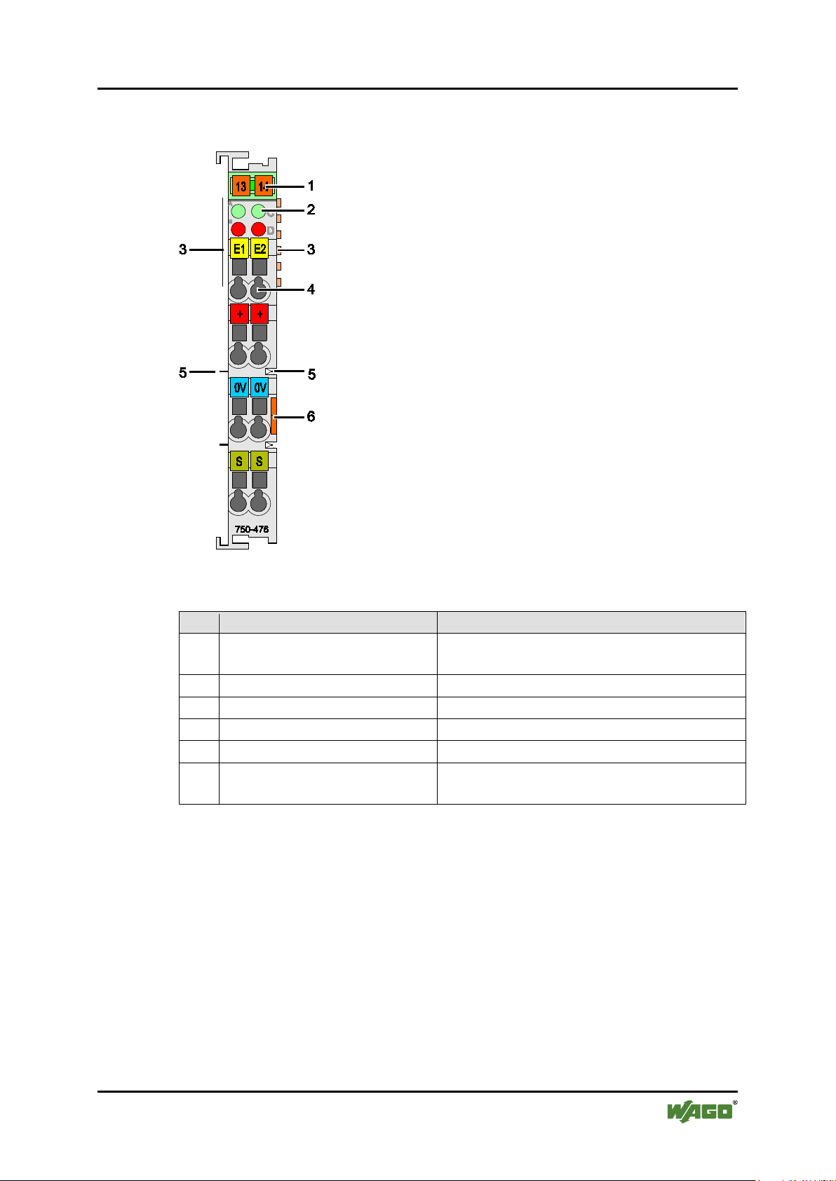
Table 3: Legend for Figure “View”
Pos.
Description
Details See Section
1
Marking possibility with MiniWSB
--2
Status LEDs
“Device Description” > “Display Elements”
3
Data contacts
“Device Description” > “Connectors”
4
CAGE CLAMP® connectors
“Device Description” > “Connectors”
5
Power jumper contacts
“Device Description” > “Connectors”
6
Release tab
“Mounting” > “Inserting and Removing
Devices”
750-476 2AI ±10V DC S.E.
Pos: 20 /Alle Serien (Allgemeine Module)/Überschr iften/Neue Überschri ften/Ebene 2Ansicht - Überschrift 2 @ 4\mod_1240 984217343_21.docx @ 31958 @ 2 @ 1
3.1 View
Pos: 21 /Serie 750 (WAGO-I/O-SYSTEM)/Gerätebeschreibung/Ansicht/An alogeingangsk lemmen/Ansicht 750-047 6 @ 21\mod_1415113945754_ 21.docx @ 167174 @ @ 1
Fig. 1: View
Pos: 22 /Serie 750 (WAGO-I/O-SYSTEM)/Gerätebeschreibung/Ansic ht/Ansicht CageCla mp®_Legende mit LEDs, mit 1 Entr iegelungslasc he @ 15\mod_1370867188922_ 21.docx @ 122225 @ @ 1
Pos: 23 /Dokumentation allgemein/Gliederungsel emente/---Seitenwechsel--- @ 3 \mod_1221108045078_0.doc x @ 21810 @ @ 1
Manual
Version 1.1.0
Page 16

16 Device Description WAGO-I/O-SYSTEM 750
750-476 2AI ±10V DC S.E.
Pos: 24 /Alle Serien (Allgemeine Module)/Überschr iften/Neue Überschri ften/Ebene 2Anschlüss e - Überschrift 2 @ 4\mod_12 40984262656_21.doc x @ 31961 @ 2 @ 1
3.2 Connectors
Pos: 25 /Serie 750 (WAGO-I/O-SYSTEM)/Gerätebeschreibung/Ansch lüsse/Datenkontak te/Klemmenbus - Übersc hrift 3 @ 6\mod_1256294 684083_21.docx @ 43660 @ 3 @ 1
3.2.1 Data Contacts/Internal Bus
Pos: 26.1 /Serie 750 (WAGO-I/O-SYSTEM)/Gerätebeschreibung/Ansc hlüsse/Datenkont akte - Feldbuskopp ler/-controller, Abbildung und Beschrei bung @ 3\mod_1231771259187_ 21.docx @ 26002 @ @ 1
Communication between the fieldbus coupler/controller and the I/O modules as
well as the system supply of the I/O modules is carried out via the internal bus. It
is comprised of 6 data contacts, which are available as self-cleaning gold spring
contacts.
Figure 2: Data Contacts
Pos: 26.2 /Serie 750 (WAGO-I/O-SYSTEM)/Wichtige Erläuterungen/Si cherheits- und sons tige Hinweise/Achtung/ Achtung: Busklem men nicht auf Goldfederko ntakte legen! @ 7\mod_126631 8463636_21.doc x @ 50695 @ @ 1
Do not place the I/O modules on the gold spring contacts!
Do not place the I/O modules on the gold spring contacts in order to avoid soiling
or scratching!
Pos: 26.3 /Serie 750 (WAGO-I/O-SYSTEM)/Wichtige Erläuterungen/Si cherheits- und sons tige Hinweise/Achtung/ Achtung: ESD - Auf gute Erdung der Umgebung achten! @ 7\mod_126 6318538667_21.doc x @ 50708 @ @ 1
Ensure that the environment is well grounded!
The devices are equipped with electronic components that may be destroyed by
electrostatic discharge. When handling the devices, ensure that the environment
(persons, workplace and packing) is well grounded. Avoid touching conductive
components, e.g. data contacts.
Pos: 27 /Dokumentation allgemein/Gliederungsel emente/---Seitenwechsel--- @ 3 \mod_1221108045078_0.doc x @ 21810 @ @ 1
Manual
Version 1.1.0
Page 17

WAGO-I/O-SYSTEM 750 Device Description 17
Table 4: Legend for Figure “Power Jumper Contacts”
Contact
Type
Function
1
Spring contact
Potential transmission (Uv) for field supply
2
Spring contact
Potential transmission (0 V) for field supply
3
Blade contact
Potential feed-in (0 V) for field supply
4
Blade contact
Potential feed-in (Uv) for field supply
750-476 2AI ±10V DC S.E.
Pos: 28 /Serie 750 (WAGO-I/O-SYSTEM)/Gerätebeschreibung/Anschlüs se/Leistungskont akte/Feldversor gung - Überschri ft 3 @ 6\mod_1256294692864_21. docx @ 43664 @ 3 @ 1
3.2.2 Power Jumper Contacts/Field Supply
Pos: 29.1 /Serie 750 (WAGO-I/O-SYSTEM)/Wichtige Erläuterungen/Si cherheits- und sons tige Hinweise/Vorsic ht/Vorsicht: Verle tzungsgefahr dur ch scharfkantige Messer kontakte! @ 6\mod_1256193 279401_21.docx @ 43414 @ @ 1
Risk of injury due to sharp-edged blade contacts!
The blade contacts are sharp-edged. Handle the I/O module carefully to prevent
injury.
Pos: 29.2 /Serie 750 (WAGO-I/O-SYSTEM)/Gerätebeschreibung/Ansc hlüsse/Leistungsko ntakte 2 LK (Messer/Lei stungskontakte 2 LK ( Messer/Feder) - Einleitung @ 15\mod_13717216 41099_21.docx @ 123714 @ @ 1
The I/O module 750-476 has 2 self-cleaning power jumper contacts that supply
and transmit power for the field side. The contacts on the left side of the I/O
module are designed as blade contacts and those on the right side as spring
contacts.
Pos: 29.3 /Serie 750 (WAGO-I/O-SYSTEM)/Gerätebeschreibung/Ansc hlüsse/Leistungsko ntakte 2 LK (Messer/Lei stungskontakte 2 LK ( Messer/Feder) - Abbi ldung, einfache Brei te - Standard @ 15\mod_136750070 0037_21.docx @ 118396 @ @ 1
Figure 3: Power Jumper Contacts
Pos: 29.4 /Serie 750 (WAGO-I/O-SYSTEM)/Gerätebeschreibung/Ansc hlüsse/Leistungsko ntakte 2 LK (Messer/Lei stungskontakte 2 LK ( Messer/Feder) - Legende @ 15\mod_1371721352500_21. docx @ 123710 @ @ 1
Pos: 29.5 /Serie 750 (WAGO-I/O-SYSTEM)/Wichtige Erläuterungen/Si cherheits- und sons tige Hinweise/Achtung/ Achtung: Maximaler Str om Leistungskontak te 10 A @ 3\mod_1226499143500_ 21.docx @ 25029 @ @ 1
Do not exceed maximum current via power jumper contacts!
The maximum current to flow through the power jumper contacts is 10 A.
Greater currents can damage the contacts.
When configuring your system, ensure that this current is not exceeded. If
exceeded, insert an additional supply module.
Pos: 29.6 /Serie 750 (WAGO-I/O-SYSTEM)/Wichtige Erläuterungen/Si cherheits- und sons tige Hinweise/Hinweis/ Hinweis: Potenti aleinspeiseklem me für Erde einsetzen! ( keine LK für Erde) @ 3\mod_122649 9037468_21.docx @ 25023 @ @ 1
Manual
Version 1.1.0
Page 18

18 Device Description WAGO-I/O-SYSTEM 750
750-476 2AI ±10V DC S.E.
Use supply modules for ground (earth)!
The I/O module has no power jumper contacts for receiving and transmitting the
earth potential. Use a supply module when an earth potential is needed for the
subsequent I/O modules.
Pos: 30 /Dokumentation allgemein/Gliederungsel emente/---Seitenwechsel--- @ 3 \mod_1221108045078_0.doc x @ 21810 @ @ 1
Manual
Version 1.1.0
Page 19

WAGO-I/O-SYSTEM 750 Device Description 19
Table 5: Legend for Figure “CAGE CLAMP® Connectors”
Channel
Designation
Connection
Function
AI 1
1
Current signal
24 V
2
Field supply Uv
0 V
3
Field supply 0 V
S
4
Shield
AI 2
5
Current signal
24 V
6
Field supply Uv
0 V
7
Field supply 0 V
S
8
Shield
750-476 2AI ±10V DC S.E.
Pos: 31 /Serie 750 (WAGO-I/O-SYSTEM)/Gerätebeschreibung/Ansch lüsse/CAGE CLAMP-Anschl üsse - Überschrif t 3 @ 6\mod_1256296337770_21.doc x @ 43674 @ 3 @ 1
3.2.3 CAGE CLAMP® Connectors
Pos: 32 /Serie 750 (WAGO-I/O-SYSTEM)/Gerätebeschreibung/Ansch lüsse/Analogeinga ngsklemmen/Anschlüss e 750-0472, -0474, - 476 @ 20\mod_1407249401134_2 1.docx @ 161193 @ @ 1
®
Figure 4: CAGE CLAMP
Connectors
1
2
Pos: 33 /Serie 750 (WAGO-I/O-SYSTEM)/Wichtige Erläuterungen/Sic herheits- und sonstige Hin weise/Hinweis/Hinweis: Geschirmte Signalleitungen verwend en! @ 7\mod_1265723251019_21.doc x @ 50140 @ @ 1
Use shielded signal lines!
Only use shielded signal lines for analog signals and I/O modules which are
equipped with shield clamps. Only then can you ensure that the accuracy and
interference immunity specified for the respective I/O module can be achieved
even in the presence of interference acting on the signal cable.
Pos: 34 /Dokumentation allgemein/Gliederungsel emente/---Seitenwechsel--- @ 3 \mod_1221108045078_0.doc x @ 21810 @ @ 1
Manual
Version 1.1.0
Page 20

20 Device Description WAGO-I/O-SYSTEM 750
Table 6: Legend for Figure “Display Elements” 750-476
Not ready for operation or no or
disturbed internal bus communication
Operational readiness and trouble-free
internal data bus communication
Off
Normal operation
Overrange/underrange of the
admissible measuring range
Not ready for operation or no or
disturbed internal bus communication
Operational readiness and trouble-free
internal data bus communication
Off
Normal operation
Overrange/underrange of the
admissible measuring range
750-476 2AI ±10V DC S.E.
Pos: 35 /Alle Serien (Allgemeine Module)/Überschr iften/Neue Überschri ften/Ebene 2Anzeigee lemente - Überschri ft 2 @ 4\mod_1240984390875_21. docx @ 31964 @ 2 @ 1
3.3 Display Elements
Pos: 36 /Serie 750 (WAGO-I/O-SYSTEM)/Gerätebeschreibung/Anzei geelemente/Analogei ngangsklemmen/An zeigeelemente 750-04 76, -0478, -0479, -0480, -0483 @ 21\mod_14144916070 38_21.docx @ 166687 @ @ 1
Figure 5: Display Elements
Channel Designation LED State Function
Function
AI1
1
Error
AI1
Function
AI2
2
Error
AI2
Pos: 37 /Alle Serien (Allgemeine Module)/Überschrif ten/Neue Überschriften/Ebene 2Bedien elemente - Überschrift 2 @ 4\mod_12391 91655456_21.doc x @ 30439 @ 2 @ 1
3.4 Operating Elements
Pos: 38 /Serie 750 (WAGO-I/O-SYSTEM)/Gerätebeschreibung/Bedie nelemente/Bediene lemente Busklemme 750- xxxx nicht vorhanden @ 4\mod_1 236322031125_21. docx @ 28063 @ @ 1
The I/O module 750-476 has no operating elements.
Pos: 39 /Dokumentation allgemein/Gliederungsel emente/---Seitenwechsel--- @ 3 \mod_1221108045078_0.doc x @ 21810 @ @ 1
A
B
C
D
Off
Green
Red
Off
Green
Red
Manual
Version 1.1.0
Page 21

WAGO-I/O-SYSTEM 750 Device Description 21
750-476 2AI ±10V DC S.E.
Pos: 40 /Alle Serien (Allgemeine Module)/Überschr iften/Neue Überschri ften/Ebene 2Schematisc hes Schaltbild - Über schrift 2 @ 4\mod_12409844413 12_21.docx @ 31967 @ 2 @ 1
3.5 Schematic Diagram
Pos: 41 /Serie 750 (WAGO-I/O-SYSTEM)/Gerätebeschreibung/Sche matische Schaltbild er/Analogeingangs klemmen/Schematisc hes Schaltbild 750-047 6 @ 24\mod_1448392412252_ 21.docx @ 196175 @ @ 1
Figure 6: Schematic Diagram
Pos: 42 /Dokumentation allgemein/Gliederungsel emente/---Seitenwechsel--- @ 3 \mod_1221108045078_0.doc x @ 21810 @ @ 1
Manual
Version 1.1.0
Page 22

22 Device Description WAGO-I/O-SYSTEM 750
Table 7: Technical Data — Device
Width
12 mm
Height (from top edge of DIN rail)
64 mm
Depth
100 mm
Weight
approx. 53 g
Table 8: Technical Data – Power Supply
Power supply
Via system voltage (DC/DC)
Current consumption, system voltage
(internal)
75 mA
Input voltage
max.
24 V
Signal voltage
±10 V
Isolation
500 V system/field side
Table 9: Technical Data – Communication
Data width, internal (internal data bus)
2 × 16 bit data
2 × 8 bit control/status (optional)
Table 10: Technical Data – Inputs
Number of inputs
2
Connection type
Single-ended
Input voltage, measurement range
−10 V … +10 V
Internal resistance
typ.
130 kΩ
Conversion time
typ.
80 ms
Resolution
15 bits plus sign bit
Measuring error at 25 °C
< ±0.1 % of full scale value
Temperature coefficient
< ±0.01 %/K of full scale value
Input filter
50 Hz
Noise rejection at sampling frequency
< −100 dB
Above sampling frequency
< −40 dB
750-476 2AI ±10V DC S.E.
Pos: 43 /Alle Serien (Allgemeine Module)/Überschr iften/Neue Überschri ften/Ebene 2Technisc he Daten - Überschrif t 2 @ 3\mod_1232967587687_21.doc x @ 26924 @ 2 @ 1
3.6 Technical Data
Pos: 44 /Serie 750 (WAGO-I/O-SYSTEM)/Gerätebeschreibung/Techni sche Daten/Analogei ngangsklemmen/ Technische Daten 750-0476 @ 24\mod_1448392474574_2 1.docx @ 196179 @ 3333 @ 1
3.6.1 Device Data
3.6.2 Power Supply
typ.
3.6.3 Communication
3.6.4 Inputs
Pos: 45 /Serie 750 (WAGO-I/O-SYSTEM)/Gerätebeschreibung/Techni sche Daten/Klimatisc he Umgebungsbedingung en/Technische Dat en Klimat. Umgebungsbed. mit erw. Temp. -20.. .+60°C/-40...+85° C für /025 @ 5\mod_1247658089120_2 1.docx @ 37606 @ 3 @ 1
Manual
Version 1.1.0
Page 23

WAGO-I/O-SYSTEM 750 Device Description 23
Table 11: Technical Data – Climatic Environmental Conditions
Operating temperature range
0 °C … 55 °C
Operating temperature range for
temperature range (750-xxx/025-xxx)
−20 °C … +60 °C
Storage temperature range
−25 °C … +85 °C
Storage temperature range for
temperature range (750-xxx/025-xxx)
−40 °C … +85 °C
Relative humidity
Max. 5 % … 95 % without condensation
Resistance to harmful substances
Acc. to IEC 60068-2-42 and
IEC 60068-2-43
Maximum pollutant concentration at
SO2 ≤ 25 ppm
H2S ≤ 10 ppm
Special conditions
Ensure that additional measures for
– ionizing radiation
Table 12: Technical Data – Field Wiring
Wire connection
CAGE CLAMP®
Cross section
0.08 mm² … 2.5 mm², AWG 28 … 14
Stripped lengths
8 mm … 9 mm / 0.33 in
Table 13: Technical Data – Power Jumper Contacts
Power jumper contacts
Blade/spring contact, self-cleaning
Voltage drop at I
max.
< 1 V/64 modules
Table 14: Technical Data – Data Contacts
Data contacts
Slide contact, hard gold plated, selfcleaning
750-476 2AI ±10V DC S.E.
3.6.5 Climatic Environmental Conditions
components with extended
components with extended
relative humidity < 75 %
components are taken, which are used in
an environment involving:
– dust, caustic vapors or gases
Pos: 46.1 /Alle Serien (Allgemeine Module)/Überschr iften/Neue Überschr iften/Ebene 3Anschl usstechnik - Übersc hrift 3 @ 17\mod_13801232713 24_21.docx @ 132788 @ 3 @ 1
3.6.6 Connection Type
Pos: 46.2 /Serie 750 (WAGO-I/O-SYSTEM)/Gerätebeschrei bung/Technische Daten/ Technische Daten Ver drahtungsebene CC - 0, 08 bis 2,5mm2 @ 17\mod_138012123 8809_21.docx @ 132780 @ @ 1
Pos: 46.3 /Serie 750 (WAGO-I/O-SYSTEM)/Gerätebeschreibung/ Technische Daten/Ansch lusstechnik/Technisc he Daten Leistungs kontakte (Messer/F eder) @ 17\mod_1380123464149 _21.docx @ 132791 @ @ 1
Pos: 46.4 /Serie 750 (WAGO-I/O-SYSTEM)/Gerätebeschreibung/ Technische Daten/Ansch lusstechnik/Technisc he Daten Datenkonta kte @ 17\mod_13801234958 44_21.docx @ 132794 @ @ 1
Pos: 47 /Dokumentation allgemein/Gliederungsel emente/---Seitenwechse l--- @ 3\mod_1221108045078_0. docx @ 21810 @ @ 1
Manual
Version 1.1.0
Page 24

24 Device Description WAGO-I/O-SYSTEM 750
Conformity Marking
CULUS
ANSI/ISA 12.12.01
Class I, Div2 ABCD T4
TÜV 07 ATEX 554086 X
I M2 Ex d I Mb
II 3 D Ex tc IIIC T135°C Dc
IECEx TUN 09.0001 X
Ex d I Mb
Ex tc IIIC T135°C Dc
TUEV 12.1297 X
Ex nA IIC T4 Gc
750-476 2AI ±10V DC S.E.
Pos: 48 /Alle Serien (Allgemeine Module)/Überschr iften/Neue Überschri ften/Ebene 2Zulassung en - Überschrift 2 @ 3\mod_1 224055364109_21.doc x @ 24030 @ 2 @ 1
3.7 Approvals
Pos: 49 /Serie 750 (WAGO-I/O-SYSTEM)/Gerätebeschreibung/Zula ssungen/Information: Weitere Infor mationen zu Zulassungen 750- xxxx @ 3\mod_122719096715 6_21.docx @ 25221 @ @ 1
More information about approvals.
Detailed references to the approvals are listed in the document “Overview
Approvals WAGO-I/O-SYSTEM 750”, which you can find via the internet
under: www.wago.com > SERVICES > DOWNLOADS > Additional
documentation and information on automation products > WAGO-I/O-SYSTEM
750 > System Description.
Pos: 50 /Serie 750 (WAGO-I/O-SYSTEM)/Gerätebeschreibung/Zula ssungen/Allgemein/ Zulassungen Buskle mme 750-xxxx Allgemein, ohn e Variantenangabe - Ei nleitung @ 4\mod_1237460656 921_21.docx @ 28643 @ @ 1
The following approvals have been granted to 750-476 I/O modules:
Pos: 51.1 /Alle Serien (Allgemeine Dokumente) (Allgem eine Module)/Zulassung en/Standardzul assungen/CE (Konfor mitätskennzeichnung) @ 3\mod_1224494777421 _21.docx @ 24276 @ @ 1
Pos: 51.2 /Alle Serien (Allgemeine Dokumente) (Allgem eine Module)/Zulassung en/Standardzul assungen/cULus (UL508) @ 3\mod_1224055013140_ 0.docx @ 24020 @ @ 1
Pos: 51.3 /Dokumentation allgemein/Gliederungs elemente/------Leerzeile------ @ 3\mod_1224662755687_0.d ocx @ 24460 @ @ 1
Pos: 52 /Alle Serien (Allgemeine Module)/Zulassung en/Standardzulassunge n/KC - Korea Certi ficate - AI @ 2 0\mod_1406533217893_21. docx @ 160376 @ @ 1
Pos: 53 /Dokumentation allgemein/Gliederungsel emente/------Leerzeile------ @ 3\mod_1224662755687_0.doc x @ 24460 @ @ 1
Pos: 54 /Serie 750 (WAGO-I/O-SYSTEM)/Gerätebeschreibung/Zula ssungen/Ex/Zulassu ngen Busklemme 750-xxxx E x, ohne Variantenangabe - Einleitung @ 4\mod_123719 1218000_21.doc x @ 28423 @ @ 1
The following Ex approvals have been granted to 750-476 I/O modules:
Pos: 55 /Alle Serien (Allgemeine Module)/Zulassung en/Ex-Zulassungen/ cULus/cULus (ANSI/I SA 12.12.01) Class I, Div2 ABCD T4 @ 3\mod_1224054791812_0. docx @ 24014 @ @ 1
Pos: 56 /Alle Serien (Allgemeine Module)/Zulassung en/Ex-Zulassungen/ TÜV ATEX/TÜV 07 ATEX 554086 X: I M2 Ex d I Mb II 3 G Ex nA IIC T4 Gc II 3 D Ex tc IIIC T135°C Dc @ 14\ mod_1361949753233_0.doc x @ 113015 @ @ 1
Pos: 57 /Alle Serien (Allgemeine Module)/Zulassung en/Ex-Zulassungen/I ECEx (TÜV Nord)/IECE x TUN 09.0001 X: Ex d I Mb Ex nA IIC T4 Gc Ex tc III C T135°C @ 14\mod_1361950034299_ 0.docx @ 113019 @ @ 1
CULUS
UL508
Korea Certification MSIP-REM-W43-AIM750
II 3 G Ex nA IIC T4 Gc
Ex nA IIC T4 Gc
Pos: 58 /Alle Serien (Allgemeine Module)/Zulassung en/Ex-Zulassungen/ Sonstige/Brasili an Ex TUEV 12.1297 X Ex nA IIC T4 Gc @ 16\mod_137 9922057421_0.doc x @ 132410 @ @ 1
Brasilian-
Pos: 59 /Dokumentation allgemein/Gliederungsel emente/---Seitenwechsel--- @ 3 \mod_1221108045078_0.doc x @ 21810 @ @ 1
Manual
Version 1.1.0
Ex
Page 25

WAGO-I/O-SYSTEM 750 Device Description 25
750-476 2AI ±10V DC S.E.
Pos: 60 /Serie 750 (WAGO-I/O-SYSTEM)/Gerätebeschreibung/Zula ssungen/Schiff /EinleitungssätzeZu lassungen Busklemme 750- xxxx Schiff, ohne Vari antenangabe - Einleitung @ 4\mod_1237190918453_21. docx @ 28420 @ @ 1
The following ship approvals have been granted to 750-476 I/O modules:
Pos: 61.1 /Alle Serien (Allgemeine Dokumente) (Allgem eine Module)/Zulassung en/Schiffszulas sungen/ABS (Americ an Bureau of Shipping) @ 3\mod_1224055151062_0.d ocx @ 24023 @ @ 1
ABS (American Bureau of Shipping)
Pos: 61.2 /Alle Serien (Allgemeine Dokumente) (Allgem eine Module)/Zulassung en/Schiff szulassungen/BSH (Bundesa mt für Seeschifff ahrt und Hydrographie) @ 5\mod_1246341825156_21.doc x @ 36334 @ @ 1
Federal Maritime and Hydrographic Agency
Pos: 61.3 /Alle Serien (Allgemeine Dokumente) (Allgem eine Module)/Zulassung en/Schiffszulas sungen/BV (Bureau Ver itas) @ 3\mod_122449211617 1_0.docx @ 24220 @ @ 1
BV (Bureau Veritas)
Pos: 61.4 /Alle Serien (Allgemeine Dokumente) (Allgem eine Module)/Zulassung en/Schiffszulas sungen/DNV (Det Norske Ver itas) Class B @ 3\mod_12244 92540562_0.doc x @ 24224 @ @ 1
DNV (Det Norske Veritas) Class B
Pos: 61.5 /Alle Serien (Allgemeine Dokumente) (Allgem eine Module)/Zulassung en/Schiffszulas sungen/GL (Germanisc her Lloyd) Cat. A, B, C, D (EMC 1) @ 3\mod_1224492724484_0.doc x @ 24228 @ @ 1
GL (Germanischer Lloyd) Cat. A, B, C, D (EMC 1)
Pos: 61.6 /Alle Serien (Allgemeine Dokumente) (Allgem eine Module)/Zulass ungen/Schiff szulassungen/KR (Korean Regi ster of Shipping) @ 3\ mod_1224492806109_0.doc x @ 24232 @ @ 1
KR (Korean Register of Shipping)
Pos: 61.7 /Alle Serien (Allgemeine Dokumente) (Allgem eine Module)/Zulassung en/Schiffszulas sungen/LR (Lloyd’s Register) Env. 1, 2, 3, 4 @ 3\mod_1224492890453_0.doc x @ 24236 @ @ 1
LR (Lloyd’s Register) Env. 1, 2, 3, 4
Pos: 61.8 /Alle Serien (Allgemeine Dokumente) (Allgem eine Module)/Zulassung en/Schiffszulas sungen/NKK (Nippon Kai ji Kyokai) @ 3\mod_122 4493002656_0.docx @ 242 40 @ @ 1
NKK (Nippon Kaiji Kyokai)
Pos: 61.9 /Alle Serien (Allgemeine Dokumente) (Allgem eine Module)/Zulassung en/Schiffszulas sungen/PRS (Polski R ejestr Statków) @ 3\mod_122 4497273250_0.doc x @ 24295 @ @ 1
PRS (Polski Rejestr Statków)
Pos: 61.10 /Alle Serien (Allgemeine Dokumente) (Allge meine Module)/Zulas sungen/Schiffszula ssungen/RINA (Regi stro Italiano Nava le) @ 3\mod_12244930 78359_0.docx @ 24244 @ @ 1
RINA (Registro Italiano Navale)
Pos: 62 /Dokumentation allgemein/Gliederungsel emente/------Leerzeile------ @ 3\mod_1224662755687_0.doc x @ 24460 @ @ 1
Pos: 63 /Alle Serien (Allgemeine Module)/Überschr iften/Neue Überschri ften/Ebene 2Normen und Richtlinien - Überschr ift 2 @ 4\mod_124280403187 5_21.docx @ 33646 @ 2 @ 1
3.8 Standards and Guidelines
Pos: 64 /Serie 750 (WAGO-I/O-SYSTEM)/Gerätebeschreibung/Normen und Richtlinien/E MV-Normen Busklemme 750- xxxx, ohne Variantenanga be - Einleitung @ 4\mod_124280 3944015_21.doc x @ 33642 @ @ 1
750-476 I/O modules meet the following requirements on emission and immunity
of interference:
Pos: 65 /Alle Serien (Allgemeine Module)/Normen und Ric htlinien/EMV-Nor men - Standard/EMV CE-Stör aussendung EN 61000-6-4 @ 4\mod_124 2798273984_21.doc x @ 33602 @ @ 1
EMC CE-Emission of interference acc. to EN 61000-6-4
Pos: 66 /Alle Serien (Allgemeine Module)/Normen und Ric htlinien/EMV-Nor men - Standard/EMV CE-Störf estigkeit EN 61000-6-2 @ 4\mod_1242 797655625_21.docx @ 335 91 @ @ 1
EMC CE-Immunity to interference acc. to EN 61000-6-2
Pos: 67 /Alle Serien (Allgemeine Module)/Normen und Ric htlinien/EMV-Nor men - Schiffbau/EMV Sc hiffbau-Störfestigkei t Germanischer Lloyd @ 4\mod_124279 8409640_21.docx @ 33610 @ @ 1
EMC marine applications-Immunity
to interference acc. to Germanischer Lloyd
Pos: 68 /Alle Serien (Allgemeine Module)/Normen und Ric htlinien/EMV-Nor men - Schiffbau/EMV Sc hiffbau-Störaussendung Ger manischer Lloyd @ 4\mod_1242 798400546_21.doc x @ 33606 @ @ 1
EMC marine applications-Emission
of interference acc. to Germanischer Lloyd
Pos: 69 /Dokumentation allgemein/Gliederungsel emente/---Seitenwechsel--- @ 3 \mod_1221108045078_0.doc x @ 21810 @ @ 1
Manual
Version 1.1.0
Page 26

26 Process Image WAGO-I/O-SYSTEM 750
Table 15: Process Image
Binary
Measured value
<-11.0
’1000.0000.0000.0000’
0x8000
-32768
0x41
ON
<-10.5
’1000.0000.0000.0000’
0x8000
-32768
0x41
OFF
-10.0
’1000.0000.0000.0000’
0x8000
-32768
0x00
OFF
-7.5
’1010.0000.0000.0000’
0xA000
-24576
0x00
OFF
-5.0
’1100.0000.0000.0000’
0xC000
-16384
0x00
OFF
-2.5
’1110.0000.0000.0000’
0xE000
-8192
0x00
OFF
0.0
’0000.0000.0000.0000’
0x0000
0
0x00
OFF
2.5
’0001.0000.0000.0000’
0x2000
8192
0x00
OFF
5.0
’0100.0000.0000.0000’
0x4000
16384
0x00
OFF
7.5
’0110.0000.00000000’
0x6000
24576
0x00
OFF
10.0
’0111.1111.1111.1111’
0x7FFF
32767
0x00
OFF
>10.5
’0111.1111.1111.1111’
0x7FFF
32767
0x42
OFF
>11.0
’0111.1111.1111.1111’
0x7FFF
32767
0x42
ON
750-476 2AI ±10V DC S.E.
Pos: 70 /Alle Serien (Allgemeine Module)/Überschr iften/Neue Überschri ften/Ebene 1Prozessab bild - Überschri ft 1 @ 4\mod_1240983067828_21.d ocx @ 31942 @ 1 @ 1
4 Process Image
Pos: 71 /Serie 750 (WAGO-I/O-SYSTEM)/Prozessabbild Klemmenbus/Hin weis: Prozessabbil dmapping abhängig von FBK/PFC, mit Status-/ Controllbyte @ 4\mod_124262 1308640_21.doc x @ 33290 @ @ 1
Mapping of process data in the process image of fieldbus systems
The representation of the I/O modules’ process data in the process image depends
on the fieldbus coupler/controller used. Please take this information as well as the
particular design of the respective control/status bytes from the section “Fieldbus
Specific Design of the Process Data” included in the description concerning the
process image of the fieldbus coupler/controller used.
Pos: 72 /Serie 750 (WAGO-I/O-SYSTEM)/Prozessabbild Klemmenbus/Ana logeingangsklem men/Prozessabbild 750-04 76 @ 5\mod_1251801974890_ 21.docx @ 41228 @ 2 @ 1
4.1 Standard Format
For the 750-476 I/O module, the input voltage range of −10 V … +10 V is scaled
to the numerical range of 0x8000 … 0x7FFF.
Input voltage ±10 V
Numeric value
Hex. Dec.
Status
Byte
Hex.
LED
Error
AI 1, 2
Pos: 73 /Dokumentation allgemein/Gliederungsel emente/---Seitenwechsel--- @ 3 \mod_1221108045078_0.doc x @ 21810 @ @ 1
Manual
Version 1.1.0
Page 27

WAGO-I/O-SYSTEM 750 Mounting 27
750-476 2AI ±10V DC S.E.
Pos: 74 /Alle Serien (Allgemeine Module)/Überschrif ten/Neue Überschriften/Ebene 1Mon tieren - Überschrift 1 @ 3\mod_1225446744 750_21.docx @ 24900 @ 1 @ 1
5 Mounting
Pos: 75.1 /Serie 750 (WAGO-I/O-SYSTEM)/Montieren/Demontieren/ Montagereihenfo lge @ 3\mod_1231770210031_21. docx @ 25992 @ 2 @ 1
5.1 Mounting Sequence
Fieldbus couplers/controllers and I/O modules of the WAGO-I/O-SYSTEM
750/753 are snapped directly on a carrier rail in accordance with the European
standard EN 50022 (DIN 35).
The reliable positioning and connection is made using a tongue and groove
system. Due to the automatic locking, the individual devices are securely seated
on the rail after installation.
Starting with the fieldbus coupler/controller, the I/O modules are mounted
adjacent to each other according to the project design. Errors in the design of the
node in terms of the potential groups (connection via the power contacts) are
recognized, as the I/O modules with power contacts (blade contacts) cannot be
linked to I/O modules with fewer power contacts.
Pos: 75.2 /Serie 750 (WAGO-I/O-SYSTEM)/Wic htige Erläuterungen/Sic herheits- und sonsti ge Hinweise/Vorsic ht/Vorsicht: Verle tzungsgefahr dur ch scharfkantige Messerkon takte! @ 6\mod_1256193279 401_21.docx @ 43414 @ @ 1
Risk of injury due to sharp-edged blade contacts!
The blade contacts are sharp-edged. Handle the I/O module carefully to prevent
injury.
Pos: 75.3 /Serie 750 (WAGO-I/O-SYSTEM)/Wichtige Erläuterungen/Si cherheits- und sons tige Hinweise/Achtu ng/Achtung: Buskle mmen nur in vorgesehener Reihenf olge stecken! @ 6\mod_12561 94177073_21.doc x @ 43429 @ @ 1
Insert I/O modules only from the proper direction!
All I/O modules feature grooves for power jumper contacts on the right side. For
some I/O modules, the grooves are closed on the top. Therefore, I/O modules
featuring a power jumper contact on the left side cannot be snapped from the top.
This mechanical coding helps to avoid configuration errors, which may destroy
the I/O modules. Therefore, insert I/O modules only from the right and from the
top.
Pos: 75.4 /Serie 750 (WAGO-I/O-SYSTEM)/Wichtige Erläuterungen/Si cherheits- und sonsti ge Hinweise/Hinweis/ Hinweis: Busabschl uss nicht vergessen! @ 6\mod_1256194225557_21.d ocx @ 43432 @ @ 1
Don't forget the bus end module!
Always plug a bus end module 750-600 onto the end of the fieldbus node! You
must always use a bus end module at all fieldbus nodes with WAGO-I/OSYSTEM 750 fieldbus couplers/controllers to guarantee proper data transfer.
Pos: 75.5 /Dokumentation allgemein/Gliederungs elemente/---Seitenwechse l--- @ 3\mod_1221108045078 _0.docx @ 21810 @ @ 1
Manual
Version 1.1.0
Page 28

28 Mounting WAGO-I/O-SYSTEM 750
750-476 2AI ±10V DC S.E.
Pos: 75.6 /Serie 750 (WAGO-I/O-SYSTEM)/Montieren/Demontieren/ Geräte einfügen und en tfernen - Überschrif t 2 @ 3\mod_1231768483250_21. docx @ 25950 @ 2 @ 1
5.2 Inserting and Removing Devices
Pos: 75.7 /Alle Serien (Allgemeine Module)/Sicher heits- und sonstige Hinweis e/Achtung/Ac htung: Arbeiten an Geräten nur spannungsfrei durc hführen! @ 6\mod_12561939635 73_21.docx @ 43426 @ @ 1
Perform work on devices only if they are de-energized!
Working on energized devices can damage them. Therefore, turn off the power
supply before working on the devices.
Pos: 75.8 /Serie 750 (WAGO-I/O-SYSTEM)/Montieren/Demontieren/B usklemme einfügen @ 3\mod_1 231769726703_21.d ocx @ 25989 @ 3 @ 1
5.2.1 Inserting the I/O Module
1. Position the I/O module so that the tongue and groove joints to the fieldbus
coupler/controller or to the previous or possibly subsequent I/O module are
engaged.
Figure 7: Insert I/O Module (Example)
2. Press the I/O module into the assembly until the I/O module snaps into the
carrier rail.
Figure 8: Snap the I/O Module into Place (Example)
With the I/O module snapped in place, the electrical connections for the data
contacts and power jumper contacts (if any) to the fieldbus coupler/controller or to
the previous or possibly subsequent I/O module are established.
Pos: 75.9 /Dokumentation allgemein/Gliederungs elemente/---Seitenwechse l--- @ 3\mod_1221108045078 _0.docx @ 21810 @ @ 1
Manual
Version 1.1.0
Page 29

WAGO-I/O-SYSTEM 750 Mounting 29
750-476 2AI ±10V DC S.E.
Pos: 75.10 /Serie 750 (WAGO-I/O-SYSTEM)/Montieren/Demontieren/B usklemme entfernen @ 4\ mod_1239169375203_21. docx @ 30334 @ 3 @ 1
5.2.2 Removing the I/O Module
1. Remove the I/O module from the assembly by pulling the release tab.
Figure 9: Removing the I/O Module (Example)
Electrical connections for data or power jumper contacts are disconnected when
removing the I/O module.
Pos: 76 /Dokumentation allgemein/Gliederungsel emente/---Seitenwechsel--- @ 3 \mod_1221108045078_0.doc x @ 21810 @ @ 1
Manual
Version 1.1.0
Page 30

30 Connect Devices WAGO-I/O-SYSTEM 750
750-476 2AI ±10V DC S.E.
Pos: 77 /Alle Serien (Allgemeine Module)/Überschr iften/Neue Überschri ften/Ebene 1Geräte ansc hließen - Überschri ft 1 @ 3\mod_1234172889468_2 1.docx @ 27460 @ 1 @ 1
6 Connect Devices
Pos: 78 /Serie 750 (WAGO-I/O-SYSTEM)/Anschließen/Leiter an CAGE CLAMP an schließen (allgemein) - Überschrift 2 und Te xt @ 3\mod_1225448660171_21. docx @ 24928 @ 2 @ 1
6.1 Connecting a Conductor to the CAGE CLAMP®
The WAGO CAGE CLAMP® connection is appropriate for solid, stranded and
finely stranded conductors.
Only connect one conductor to each CAGE CLAMP®!
Only one conductor may be connected to each CAGE CLAMP®.
Do not connect more than one conductor at one single connection!
If more than one conductor must be routed to one connection, these must be
connected in an up-circuit wiring assembly, for example using WAGO feedthrough terminals.
1. For opening the CAGE CLAMP® insert the actuating tool into the opening
above the connection.
2. Insert the conductor into the corresponding connection opening.
3. For closing the CAGE CLAMP® simply remove the tool. The conductor is
now clamped firmly in place.
Figure 10: Connecting a Conductor to a CAGE CLAMP
Pos: 79 /Dokumentation allgemein/Gliederungsel emente/---Seitenwechsel--- @ 3 \mod_1221108045078_0.doc x @ 21810 @ @ 1
®
Manual
Version 1.1.0
Page 31

WAGO-I/O-SYSTEM 750 Connect Devices 31
750-476 2AI ±10V DC S.E.
Pos: 80 /Alle Serien (Allgemeine Module)/Überschr iften/Neue Überschri ften/Ebene 2Anschluss beispiel - Überschr ift 2 @ 4\mod_1242621672468 _21.docx @ 33293 @ 2 @ 1
6.2 Connection Example
Pos: 81 /Serie 750 (WAGO-I/O-SYSTEM)/Wichtige Erläuterungen/Sic herheits- und sonstige Hinweise/ Hinweis/Hinweis: Geschir mte Signalleitungen verwenden! @ 7\mod_1265723251019_21.docx @ 50140 @ @ 1
Use shielded signal lines!
Only use shielded signal lines for analog signals and I/O modules which are
equipped with shield clamps. Only then can you ensure that the accuracy and
interference immunity specified for the respective I/O module can be achieved
even in the presence of interference acting on the signal cable.
Pos: 82 /Serie 750 (WAGO-I/O-SYSTEM)/Anschließ en/Anschlussbeispie le/Analogeingangs klemmen/Anschlus sbeispiel 750-0476 @ 24\mod_14 48392625129_21.doc x @ 196183 @ @ 1
Figure 11: Connection Example
Pos: 83 /Dokumentation allgemein/Gliederungsel emente/---Seitenwechsel--- @ 3 \mod_1221108045078_0.doc x @ 21810 @ @ 1
Manual
Version 1.1.0
Page 32

32 Use in Hazardous Environments WAGO-I/O-SYSTEM 750
750-476 2AI ±10V DC S.E.
Pos: 84.1 /Alle Serien (Allgemeine Module)/Einsatz i n Ex-Bereichen/Ei nsatz in explosionsgefähr deten Bereichen - Überschrift 1 @ 3\mod_122407519 1281_21.docx @ 24084 @ 1 @ 1
7 Use in Hazardous Environments
Pos: 84.2 /Serie 750 (WAGO-I/O-SYSTEM)/Einsatz in Ex-Bereichen/Einsatzber eich Serie 750 @ 3\mod_123427 2230203_21.doc x @ 27500 @ @ 1
The WAGO-I/O-SYSTEM 750 (electrical equipment) is designed for use in
Zone 2 hazardous areas.
The following sections include both the general identification of components
(devices) and the installation regulations to be observed. The individual
subsections of the “Installation Regulations” section must be taken into account if
the I/O module has the required approval or is subject to the range of application
of the ATEX directive.
Pos: 84.3 /Dokumentation allgemein/Gliederungs elemente/---Seitenwechse l--- @ 3\mod_1221108045078 _0.docx @ 21810 @ @ 1
Manual
Version 1.1.0
Page 33

WAGO-I/O-SYSTEM 750 Use in Hazardous Environments 33
750-476 2AI ±10V DC S.E.
Pos: 84.4 /Serie 750 (WAGO-I/O-SYSTEM)/Einsatz in Ex-Bereichen/Beispielhaf ter Aufbau der Kennzeic hnung - Überschrif t 2 @ 3\mod_1224157499140_21.doc x @ 24182 @ 2 @ 1
7.1 Marking Configuration Examples
Pos: 84.5 /Serie 750 (WAGO-I/O-SYSTEM)/Einsatz in Ex-Bereichen/Kennzeichnung f ür Europa gemäß ATEX und IEC -EX - Überschrift 3 @ 3\mod_12241576 20203_21.docx @ 24185 @ 3 @ 1
7.1.1 Marking for Europe According to ATEX and IEC-Ex
Pos: 84.6 /Serie 750 (WAGO-I/O-SYSTEM)/Einsatz in Ex-Bereichen/Beispielbedr uckung der ATEX- und IEC- Ex-zugelassenen Busklem men gemäß CENELEC und IEC_2013 @ 14\ mod_1360569228625_21. docx @ 111294 @ @ 1
Figure 12: Side Marking Example for Approved I/O Modules According to ATEX and IECEx
Figure 13: Text Detail – Marking Example for Approved I/O Modules According to ATEX and
IECEx.
Manual
Version 1.1.0
Page 34

34 Use in Hazardous Environments WAGO-I/O-SYSTEM 750
Table 16: Description of Marking Example for Approved I/O Modules According to ATEX and
IECEx
Printing on Text
Description
TÜV 07 ATEX 554086 X
IECEx TUN 09.0001 X
Approving authority and certificate numbers
Dust
II
Equipment group: All except mining
3D
Category 3 (Zone 22)
Ex
Explosion protection mark
tc Dc
Type of protection and equipment protection
level (EPL):protection by enclosure
IIIC
Explosion group of dust
T 135°C
Max. surface temperature of the enclosure
(without a dust layer)
Mining
I
Equipment group: Mining
M2
Category: High level of protection
Ex
Explosion protection mark
d Mb
Type of protection and equipment protection
level (EPL): Flameproof enclosure
I
Explosion group for electrical equipment for
mines susceptible to firedamp
Gases
II
Equipment group: All except mining
3G
Category 3 (Zone 2)
Ex
Explosion protection mark
nA Gc
Type of protection and equipment protection
level (EPL): Non-sparking equipment
nC Gc
Type of protection and equipment protection
interior
IIC
Explosion group of gas and vapours
T4
Temperature class: Max. surface temperature
135°C
750-476 2AI ±10V DC S.E.
Pos: 84.7 /Dokumentation allgemein/Gliederungs elemente/---Seitenwechse l--- @ 3\mod_1221108045078 _0.docx @ 21810 @ @ 1
Manual
Version 1.1.0
level (EPL): Sparking apparatus with protected
contacts. A device which is so constructed that
the external atmosphere cannot gain access to the
Page 35

WAGO-I/O-SYSTEM 750 Use in Hazardous Environments 35
750-476 2AI ±10V DC S.E.
Pos: 84.8 /Serie 750 (WAGO-I/O-SYSTEM)/Einsatz in Ex-Bereichen/Beispielbedr uckung der Ex-i- und IEC- Ex-i-zugelassenen Busklemme n gemäß CENELEC und IEC_2013 @ 14\ mod_1360569320118_21. docx @ 111298 @ @ 1
Figure 14: Side Marking Example for Approved Ex i I/O Modules According to ATEX and
IECEx.
Figure 15: Text Detail – Marking Example for Approved Ex i I/O Modules According to ATEX
and IECEx.
Manual
Version 1.1.0
Page 36

36 Use in Hazardous Environments WAGO-I/O-SYSTEM 750
Table 17: Description of Marking Example for Approved Ex i I/O Modules According to ATEX and
IECEx
Inscription Text
Description
TÜV 07 ATEX 554086 X
IECEx TUN 12.0039 X
Approving authority and certificate numbers
Dust
II
Equipment group: All except mining
3(1)D
Category 3 (Zone 22) equipment containing a safety
device for a category 1 (Zone 20) equipment
3(2)D
Category 3 (Zone 22) equipment containing a safety
device for a category 2 (Zone 21) equipment
Ex
Explosion protection mark
tc Dc
Type of protection and equipment protection level
(EPL): protection by enclosure
[ia Da]
Type of protection and equipment protection level
circuits for use in Zone 20
[ib Db]
Type of protection and equipment protection level
circuits for use in Zone 21
IIIC
Explosion group of dust
T 135°C
Max. surface temperature of the enclosure (without a
dust layer)
Mining
I
Equipment Group: Mining
M2 (M1)
Category: High level of protection with electrical
circuits which present a very high level of protection
Ex d Mb
Explosion protection mark with Type of protection
enclosure
[ia Ma]
Type of protection and equipment protection level
electrical circuits
I Explosion group for electrical equipment for mines
susceptible to firedamp
750-476 2AI ±10V DC S.E.
IECEx TUN 09.0001X
TÜV 12 ATEX 106032 X
(EPL): associated apparatus with intrinsic safety
(EPL): associated apparatus with intrinsic safety
and equipment protection level (EPL): Flameproof
(EPL): associated apparatus with intrinsic safety
Manual
Version 1.1.0
Page 37

WAGO-I/O-SYSTEM 750 Use in Hazardous Environments 37
Table 17: Description of Marking Example for Approved Ex i I/O Modules According to ATEX and
IECEx
Gases
II
Equipment group: All except mining
3(1)G
Category 3 (Zone 2) equipment containing a safety
device for a category 1 (Zone 0) equipment
3(2)G
Category 3 (Zone 2) equipment containing a safety
device for a category 2 (Zone 1) equipment
Ex
Explosion protection mark
nA Gc
Type of protection and equipment protection level
(EPL): Non-sparking equipment
[ia Ga]
Type of protection and equipment protection level
circuits for use in Zone 0
[ia Gb]
Type of protection and equipment protection level
circuits for use in Zone 1
IIC
Explosion group of gas and vapours
T4
Temperature class: Max. surface temperature 135°C
750-476 2AI ±10V DC S.E.
(EPL): associated apparatus with intrinsic safety
(EPL): associated apparatus with intrinsic safety
Pos: 84.9 /Dokumentation allgemein/Gliederungs elemente/---Seitenwechse l--- @ 3\mod_1221108045078 _0.docx @ 21810 @ @ 1
Manual
Version 1.1.0
Page 38

38 Use in Hazardous Environments WAGO-I/O-SYSTEM 750
Table 18: Description of Marking Example for Approved I/O Modules According to NEC 500
Printing on Text
Description
CL I
Explosion protection group (condition of use
category)
DIV 2
Area of application
Grp. ABCD
Explosion group (gas group)
Op temp code T4
Temperature class
750-476 2AI ±10V DC S.E.
Pos: 84.10 /Serie 750 (WAGO-I/O-SYSTEM)/Einsatz in Ex-Bereichen/Kennzeichnun g für Amerika gemäß NEC 500 - Über schrift 3 @ 3\mod_1224158 423187_21.docx @ 24188 @ 3 @ 1
7.1.2 Marking for America According to NEC 500
Pos: 84.11 /Serie 750 (WAGO-I/O-SYSTEM)/Einsatz in Ex-Bereichen/Beispielbedr uckung gemäß NEC 500_2013 @ 14\ mod_1360580302684_2 1.docx @ 111353 @ @ 1
Figure 16: Side Marking Example for I/O Modules According to NEC 500
Figure 17: Text Detail – Marking Example for Approved I/O Modules According to NEC 500
Pos: 84.12 /Dokumentation allgemein/Gliederung selemente/---Seitenwechse l--- @ 3\mod_1221108045078_0.doc x @ 21810 @ @ 1
Manual
Version 1.1.0
Page 39

WAGO-I/O-SYSTEM 750 Use in Hazardous Environments 39
750-476 2AI ±10V DC S.E.
Pos: 84.13 /Alle Serien (Allgemeine Module)/Einsatz i n Ex-Bereichen/Err ichtungsbestimmung en - Überschrift 2 @ 3\ mod_1232453624234_21.doc x @ 26370 @ 2 @ 1
7.2 Installation Regulations
Pos: 84.14 /Alle Serien (Allgemeine Module)/Einsatz i n Ex-Bereichen/Err ichtungsbestimmung en Einleitung_2013 @ 14\mod_1 360582328318_2 1.docx @ 111371 @ @ 1
For the installation and operation of electrical equipment in hazardous areas, the
valid national and international rules and regulations which are applicable at the
installation location must be carefully followed.
Pos: 84.15 /Dokumentation allgemein/Gliederung selemente/---Seitenwechse l--- @ 3\mod_122110804507 8_0.docx @ 21810 @ @ 1
Manual
Version 1.1.0
Page 40

40 Use in Hazardous Environments WAGO-I/O-SYSTEM 750
750-476 2AI ±10V DC S.E.
Pos: 84.16 /Serie 750 (WAGO-I/O-SYSTEM)/Einsatz in Ex-Bereichen/Besondere Bedi ngungen für den sicher en Ex-Betrieb gem. ATEX-Ze rtifikat TÜV 07 ATEX 554086_X _2013_2 @ 15\mod_13686200 71975_21.docx @ 119778 @ 3 @ 1
7.2.1 Special Conditions for Safe Use (ATEX Certificate TÜV 07 ATEX 554086 X)
1. For use as Gc- or Dc-apparatus (in zone 2 or 22) the Field bus Independent
I/O Modules WAGO-I/O-SYSTEM 750-*** shall be erected in an
enclosure that fulfils the requirements of the applicable standards (see the
marking) EN 60079-0, EN 60079-11, EN 60079-15 and EN 60079-31.
For use as group I electrical apparatus M2 the apparatus shall be erected in
an enclosure that ensures a sufficient protection according to EN 60079-0
and EN 60079-1 and the degree of protection IP64.
The compliance of these requirements and the correct installation into an
enclosure or a control cabinet of the devices shall be certified by an ExNB.
2. Measures have to be taken outside of the device that the rating voltage is not
being exceeded of more than 40 % because of transient disturbances.
3. Dip-switches, binary-switches and potentiometers, connected to the module
may only be actuated when explosive atmosphere can be excluded.
4. The connecting and disconnecting of the non-intrinsically safe circuits is
only permitted during installation, for maintenance or for repair purposes.
The temporal coincidence of explosion hazardous atmosphere and
installation, maintenance resp. repair purposes shall be excluded.
This is although and in particular valid for the interfaces “Memory-Card”,
“USB”, “Fieldbus connection”, “Configuration and programming interface”,
“antenna socket”, “D-Sub”, “DVI-port” and the “Ethernet interface”. These
interfaces are not energy limited or intrinsically safe circuits. An operating
of those circuits is in the behalf of the operator.
5. For the types 750-606, 750-625/000-001, 750-487/003-000, 750-484 and
750-633 the following shall be considered: The Interface circuits shall be
limited to overvoltage category I/II/III (non mains/mains circuits) as defined
in EN 60664-1.
6. For replaceable fuses the following shall be considered: Do not remove or
replace the fuse when the apparatus is energized.
7. The following warnings shall be placed nearby the unit:
WARNING – DO NOT REMOVE OR REPLACE FUSE WHEN
ENERGIZED
WARNING – DO NOT SEPARATE WHEN ENERGIZED
WARNING – SEPARATE ONLY IN A NON-HAZARDOUS AREA
Pos: 84.17 /Dokumentation allgemein/Gliederung selemente/---Seitenwechse l--- @ 3\mod_1221108045078_0.doc x @ 21810 @ @ 1
Manual
Version 1.1.0
Page 41

WAGO-I/O-SYSTEM 750 Use in Hazardous Environments 41
750-476 2AI ±10V DC S.E.
Pos: 84.18 /Serie 750 (WAGO-I/O-SYSTEM)/Einsatz in Ex-Bereichen/Besondere Bedi ngungen für den sicher en Ex-Betrieb gem. ATEX-Zer tifikat TÜV 12 ATEX 106032x_201 3_2 @ 15\mod_136862047945 4_21.docx @ 119782 @ 3 @ 1
7.2.2 Special Conditions for Safe Use (ATEX Certificate TÜV 12 ATEX 106032 X)
1. For use as Gc- or Dc-apparatus (in zone 2 or 22) the Field bus Independent
I/O Modules WAGO-I/O-SYSTEM 750-*** Ex i shall be erected in an
enclosure that fulfils the requirements of the applicable standards (see the
marking) EN 60079-0, EN 60079-11, EN 60079-15 and EN 60079-31.
For use as group I electrical apparatus M2 the apparatus shall be erected in
an enclosure that ensures a sufficient protection according to EN 60079-0
and EN 60079-1 and the degree of protection IP64.
The compliance of these requirements and the correct installation into an
enclosure or a control cabinet of the devices shall be certified by an ExNB.
2. Measures have to be taken outside of the device that the rating voltage is not
being exceeded of more than 40 % because of transient disturbances.
3. The connecting and disconnecting of the non-intrinsically safe circuits is
only permitted during installation, for maintenance or for repair purposes.
The temporal coincidence of explosion hazardous atmosphere and
installation, maintenance resp. repair purposes shall be excluded.
4. For the type the following shall be considered: The Interface circuits shall
be limited to overvoltage category I/II (non mains/mains circuits) as defined
in EN 60664-1.
Pos: 84.19 /Dokumentation allgemein/Gliederung selemente/---Seitenwechse l--- @ 3\mod_1221108045078_0.doc x @ 21810 @ @ 1
Manual
Version 1.1.0
Page 42

42 Use in Hazardous Environments WAGO-I/O-SYSTEM 750
750-476 2AI ±10V DC S.E.
Pos: 84.20 /Serie 750 (WAGO-I/O-SYSTEM)/Einsatz in Ex-Bereichen/Besondere Bedi ngungen für den sicher en Ex-Betrieb gem. IEC-Ex- Zertifikat TUN 09.0001 X_ 2013_2 @ 15\mod_136862066091 1_21.docx @ 119786 @ 3 @ 1
7.2.3 Special Conditions for Safe Use (IEC-Ex Certificate TUN
09.0001 X)
1. For use as Gc- or Dc-apparatus (in zone 2 or 22) the Field bus Independent
I/O Modules WAGO-I/O-SYSTEM 750-*** shall be erected in an
enclosure that fulfils the requirements of the applicable standards (see the
marking) IEC 60079-0, IEC 60079-11, IEC 60079-15 and IEC 60079-31.
For use as group I electrical apparatus M2 the apparatus shall be erected in
an enclosure that ensures a sufficient protection according to IEC 60079-0
and IEC 60079-1 and the degree of protection IP64.
The compliance of these requirements and the correct installation into an
enclosure or a control cabinet of the devices shall be certified by an ExCB.
2. Measures have to be taken outside of the device that the rating voltage is not
being exceeded of more than 40 % because of transient disturbances.
3. DIP-switches, binary-switches and potentiometers, connected to the module
may only be actuated when explosive atmosphere can be excluded.
4. The connecting and disconnecting of the non-intrinsically safe circuits is
only permitted during installation, for maintenance or for repair purposes.
The temporal coincidence of explosion hazardous atmosphere and
installation, maintenance resp. repair purposes shall be excluded.
This is although and in particular valid for the interfaces “Memory-Card”,
“USB”, “Fieldbus connection”, “Configuration and programming interface”,
“antenna socket”, “D-Sub”, “DVI-port” and the “Ethernet interface”. These
interfaces are not energy limited or intrinsically safe circuits. An operating
of those circuits is in the behalf of the operator.
5. For the types 750-606, 750-625/000-001, 750-487/003-000, 750-484 and
750-633 the following shall be considered: The Interface circuits shall be
limited to overvoltage category I/II/III (non mains/mains circuits) as defined
in IEC 60664-1.
6. For replaceable fuses the following shall be considered: Do not remove or
replace the fuse when the apparatus is energized.
7. The following warnings shall be placed nearby the unit:
WARNING – DO NOT REMOVE OR REPLACE FUSE WHEN
ENERGIZED
WARNING – DO NOT SEPARATE WHEN ENERGIZED
WARNING – SEPARATE ONLY IN A NON-HAZARDOUS AREA
Pos: 84.21 /Dokumentation allgemein/Gliederung selemente/---Seitenwechse l--- @ 3\mod_1221108045078_0.doc x @ 21810 @ @ 1
Manual
Version 1.1.0
Page 43

WAGO-I/O-SYSTEM 750 Use in Hazardous Environments 43
750-476 2AI ±10V DC S.E.
Pos: 84.22 /Serie 750 (WAGO-I/O-SYSTEM)/Einsatz in Ex-Bereichen/Besondere Bedi ngungen für den sicher en Ex-Betrieb gem. IEC-Ex- Zertifikat TUN 12.0039 X_ 2013_2 @ 15\mod_136862082149 3_21.docx @ 119790 @ 3 @ 1
7.2.4 Special Conditions for Safe Use (IEC-Ex Certificate IECEx TUN 12.0039 X)
1. For use as Gc- or Dc-apparatus (in zone 2 or 22) the Field bus independent
I/O Modules WAGO-I/O-SYSTEM 750-*** Ex i shall be erected in an
enclosure that fulfils the requirements of the applicable standards (see the
marking) IEC 60079-0, IEC 60079-11, IEC 60079-15, IEC 60079-31.
For use as group I electrical apparatus M2 the apparatus shall be erected in
an enclosure that ensures a sufficient protection according to IEC 60079-0
and IEC 60079-1 and the degree of protection IP64.
The compliance of these requirements and the correct installation into an
enclosure or a control cabinet of the devices shall be certified by an ExCB.
2. Measures have to be taken outside of the device that the rating voltage is not
being exceeded of more than 40 % because of transient disturbances.
3. The connecting and disconnecting of the non-intrinsically safe circuits is
only permitted during installation, for maintenance or for repair purposes.
The temporal coincidence of explosion hazardous atmosphere and
installation, maintenance resp. repair purposes shall be excluded.
4. For the type the following shall be considered: The Interface circuits shall
be limited to overvoltage category I/II (non mains/mains circuits) as defined
in IEC 60664-1.
Pos: 84.23 /Dokumentation allgemein/Gliederung selemente/---Seitenwechse l--- @ 3\mod_1221108045078_0.doc x @ 21810 @ @ 1
Manual
Version 1.1.0
Page 44

44 Use in Hazardous Environments WAGO-I/O-SYSTEM 750
750-476 2AI ±10V DC S.E.
Pos: 84.24 /Serie 750 (WAGO-I/O-SYSTEM)/Einsatz in Ex-Bereichen/Erric htungsbestimmungen ANSI ISA 12. 12.01_2013_2 @ 15\mod_1 368620942842_21.doc x @ 119794 @ 3 @ 1
7.2.5 Special Conditions for Safe Use According to ANSI/ISA
12.12.01
A. “This equipment is suitable for use in Class I, Division 2, Groups A, B, C, D
or non-hazardous locations only.”
B. “This equipment is to be fitted within tool-secured enclosures only.”
C. “WARNING Explosion hazard - substitution of components may impair
suitability for Class I, Div. 2.”
D. “WARNING – Do not disconnect equipment unless power has been
switched off or the area is known to be non-hazardous” has to be placed
near each operator accessible connector and fuse holder.
E. When a fuse is provided, the following information shall be provided: “A
switch suitable for the location where the equipment is installed shall be
provided to remove the power from the fuse.”
F. For devices with EtherCAT/Ethernet connectors “Only for use in LAN, not
for connection to telecommunication circuits.”
G. “WARNING - Use Module 750-642 only with antenna module 758-910.”
H. For Couplers/Controllers and Economy bus modules only: The instructions
shall contain the following: “The configuration interface Service connector
is for temporary connection only. Do not connect or disconnect unless the
area is known to be non-hazardous. Connection or disconnection in an
explosive atmosphere could result in an explosion.”
I. Modules containing fuses only: “WARNING - Devices containing fuses
must not be fitted into circuits subject to over loads, e.g. motor circuits.”
J. Modules containing SD card reader sockets only: “WARNING - Do not
connect or disconnect SD-Card while circuit is live unless the area is known
Pos: 84.25 /Dokumentation allgemein/Gliederung selemente/------Leerzeile------ @ 3\mod_1224662755687_0. docx @ 24460 @ @ 1
Pos: 84.26 /Dokumentation allgemein/Gliederung selemente/------Leerzeile------ @ 3\mod_1224662755687_0. docx @ 24460 @ @ 1
Pos: 84.27 /Dokumentation allgemein/Gliederung selemente/------Leerzeile------ @ 3\mod_1224662755687_0. docx @ 24460 @ @ 1
Pos: 84.28 /Serie 750 (WAGO-I/O-SYSTEM)/Einsatz in Ex-Bereichen/ Information: Zertif izierungsnachwei s @ 7\mod_1274279547729_2 1.docx @ 56649 @ @ 1
=== Ende der Liste für Textmarke Inhalt_mitte ===
to be free of ignitable concentrations of flammable gases or vapors.”
Additional Information
Proof of certification is available on request.
Also take note of the information given on the operating and assembly
instructions.
The manual, containing these special conditions for safe use, must be readily
available to the user.
Manual
Version 1.1.0
Page 45

WAGO-I/O-SYSTEM 750 List of Figures 45
750-476 2AI ±10V DC S.E.
Pos: 86 /Dokumentation allgemein/Verzeichnisse/ Abbildungsverzeic hnis - Überschrif t oG und Verzeichnis @ 3\mod_12192 22916765_21.doc x @ 21080 @ @ 1
List of Figures
Fig. 1: View ........................................................................................................... 15
Figure 2: Data Contacts ......................................................................................... 16
Figure 3: Power Jumper Contacts ......................................................................... 17
Figure 4: CAGE CLAMP® Connectors................................................................. 19
Figure 5: Display Elements ................................................................................... 20
Figure 6: Schematic Diagram ................................................................................ 21
Figure 7: Insert I/O Module (Example) ................................................................. 28
Figure 8: Snap the I/O Module into Place (Example) ........................................... 28
Figure 9: Removing the I/O Module (Example) ................................................... 29
Figure 10: Connecting a Conductor to a CAGE CLAMP® ................................... 30
Figure 11: Connection Example ............................................................................ 31
Figure 12: Side Marking Example for Approved I/O Modules According to
ATEX and IECEx ........................................................................................ 33
Figure 13: Text Detail – Marking Example for Approved I/O Modules
According to ATEX and IECEx. ................................................................. 33
Figure 14: Side Marking Example for Approved Ex i I/O Modules
According to ATEX and IECEx. ................................................................. 35
Figure 15: Text Detail – Marking Example for Approved Ex i I/O Modules
According to ATEX and IECEx. ................................................................. 35
Figure 16: Side Marking Example for I/O Modules According to NEC 500 ....... 38
Figure 17: Text Detail – Marking Example for Approved I/O Modules
According to NEC 500................................................................................. 38
Pos: 87 /Dokumentation allgemein/Gliederungsel emente/---Seitenwechsel--- @ 3 \mod_1221108045078_0.doc x @ 21810 @ @ 1
Manual
Version 1.1.0
Page 46

46 List of Tables WAGO-I/O-SYSTEM 750
750-476 2AI ±10V DC S.E.
Pos: 88 /Dokumentation allgemein/Verzeichnisse/ Tabellenverzeic hnis - Überschrif t oG und Verzeichnis @ 3\mod_1219222 958703_21.docx @ 21084 @ @ 1
List of Tables
Table 1: Number Notation ....................................................................................... 8
Table 2: Font Conventions ...................................................................................... 8
Table 3: Legend for Figure “View” ...................................................................... 15
Table 4: Legend for Figure “Power Jumper Contacts” ......................................... 17
Table 5: Legend for Figure “CAGE CLAMP® Connectors” ................................ 19
Table 6: Legend for Figure “Display Elements” 750-476 .................................... 20
Table 7: Technical Data — Device ....................................................................... 22
Table 8: Technical Data – Power Supply .............................................................. 22
Table 9: Technical Data – Communication ........................................................... 22
Table 10: Technical Data – Inputs ........................................................................ 22
Table 11: Technical Data – Climatic Environmental Conditions ......................... 23
Table 12: Technical Data – Field Wiring .............................................................. 23
Table 13: Technical Data – Power Jumper Contacts ............................................ 23
Table 14: Technical Data – Data Contacts ............................................................ 23
Table 15: Process Image ........................................................................................ 26
Table 16: Description of Marking Example for Approved I/O Modules
According to ATEX and IECEx .................................................................. 34
Table 17: Description of Marking Example for Approved Ex i I/O Modules
According to ATEX and IECEx .................................................................. 36
Table 18: Description of Marking Example for Approved I/O Modules
According to NEC 500................................................................................. 38
Pos: 89 /Dokumentation allgemein/Einband/Einband Handbuch - Leerseite für durch 2 teilbare Seitenza hl (Standarddruc k) @ 3\mod_1219230851078 _0.docx @ 21123 @ @ 1
Manual
Version 1.1.0
Page 47

WAGO-I/O-SYSTEM 750 List of Tables 47
750-476 2AI ±10V DC S.E.
=== Ende der Liste für Textmarke Verzeichnis_hinten ===
Manual
Version 1.1.0
Page 48

WAGO Kontakttechnik GmbH & Co. KG
Postfach 2880 •
D-32385 Minden
Hansastraße 27 •
D-32423 Minden
Phone:
05 71/8 87 – 0
Fax:
05 71/8 87 – 1 69
E-Mail:
info@wago.com
Internet:
http://www.wago.com
Pos: 91 /Dokumentation allgemein/Einband/Einband Handbuch - Rückseite 2015 @ 9\mod_1285229376516_21. docx @ 64944 @ @ 1
=== Ende der Liste für Textmarke Einband_hinten ===
 Loading...