

Page 1
Pos: 2 /Do kumentation allgemein /Einband/ Einband H andbuch - De ckblatt o hne Varia ntenfeld (S tandard) @ 9\mod_1285229289866_0 .doc @ 64941 @ @ 1
Manual
WAGO-I/O-SYSTEM 750
Channel Relay Ou t put Module AC 230 V, DC 30 V,
2DO 230V AC 2.0A/ Relay 2NO
750-512
2-
non-floating; 2 make contacts
Version 1.2.0
Pos: 3 /Alle Serien (Al lgemeine M odule)/H inweise zur Dokumen tation/Im pressum für St a nd ar d handbüch er - all g . Ang aben, Ansc hr if ten, Telef on n ummern und E-M ail-Adress en @ 3\mod_1219151118203_21.doc @ 21 060 @ @ 1
Page 2

2 WAGO-I/O-SYSTEM 750
750-512 2DO 230V AC 2.0A/ Relay 2NO
© 2013 by WAGO Kontakttechnik GmbH & Co. KG
All rights reserved.
WAGO Kontakttechnik GmbH & Co. KG
Hansastraße 27
D-32423 Minden
Phone: +49 (0) 571/8 87 – 0
Fax: +49 (0) 571/8 87 – 1 69
E-Mail: info@wago.com
Web: http://www.wago.com
=== Ende der Liste für Textmar ke Einband _vorne ===
Technical Support
Phone: +49 (0) 571/8 87 – 5 55
Fax: +49 (0) 571/8 87 – 85 55
E-Mail: support@wago.com
Every conceivable measure has been taken to ensure the accuracy and
completeness of this documentation. However, as errors can never be fully
excluded, we always appreciate any information or suggestions for improving the
documentation.
E-Mail: documentation@wago.com
We wish to point out that the software and hardware terms as well as the
trademarks of companies used and/or mentioned in the present manual are
generally protected by trademark or patent.
Manual
Version 1.2.0
Page 3

WAGO-I/O-SYSTEM 750 Table of Contents 3
750-512 2DO 230V AC 2.0A/ Relay 2NO
Pos: 5 /Do kumentation allgemein /Verzeich nisse/Inh altsverzei chnis - Über schrift oG und Verzei chnis @ 3 \mod_1219151230875_21.doc @ 21063 @ @ 1
Table of Contents
1 Notes about this Documentation ................................................................. 5
1.1 Validity of this Documentation ................................................................. 5
1.2 Copyright ................................................................................................... 5
1.3 Symbols ..................................................................................................... 6
1.4 Number Notation ....................................................................................... 8
1.5 Font Conventions ...................................................................................... 8
2 Important Notes ........................................................................................... 9
2.1 Legal Bases ............................................................................................... 9
2.1.1 Subject to Changes ............................................................................... 9
2.1.2 Personnel Qualifications ....................................................................... 9
2.1.3 Use of the 750 Series in Compliance with Underlying Provisions ...... 9
2.1.4 Technical Condition of Specified Devices ......................................... 10
2.2 Safety Advice (Precautions) .................................................................... 11
3 Device Description ..................................................................................... 13
3.1 View ........................................................................................................ 15
3.2 Connectors ............................................................................................... 16
3.2.1 Data Contacts/Internal Bus ................................................................. 16
3.2.2 Power Jumper Contacts/Field Supply ................................................ 17
3.2.3 CAGE CLAMP® Connections ........................................................... 18
3.3 Display Elements .................................................................................... 19
3.4 Operating Elements ................................................................................. 19
3.5 Schematic Diagram ................................................................................. 20
3.6 Technical Data ........................................................................................ 21
3.6.1 Device Data ........................................................................................ 21
3.6.2 Power Supply...................................................................................... 21
3.6.3 Communication .................................................................................. 21
3.6.4 Outputs ............................................................................................... 21
3.7 Approvals ................................................................................................ 22
3.8 Standards and Guidelines ........................................................................ 23
4 Mounting ..................................................................................................... 24
4.1 Mounting Sequence ................................................................................. 24
4.2 Inserting and Removing Devices ............................................................ 25
4.2.1 Inserting I/O Module .......................................................................... 25
4.2.2 Removing the I/O Module .................................................................. 26
5 Connect Devices ......................................................................................... 27
5.1 Connecting a Conductor to the CAGE CLAMP® ................................... 27
5.2 Connection Examples .............................................................................. 28
5.2.1 2-Conductor Connection, ungrounded ............................................... 28
5.2.2 2-Conductor Connection, grounded ................................................... 28
5.2.3 3-Conductor Connection, ungrounded ............................................... 29
5.2.4 3-Conductor Connection, grounded ................................................... 29
6 Process Image ............................................................................................. 30
7 Use in Hazardous Environments .............................................................. 31
Manual
Version 1.2.0
Page 4

4 Table of Contents WAGO-I/O-SYSTEM 750
750-512 2DO 230V AC 2.0A/ Relay 2NO
7.1 Marking Configuration Examples ........................................................... 32
7.1.1 Marking for Europe according to ATEX and IEC-Ex ........................ 32
7.1.2 Marking for America according to NEC 500 ..................................... 37
7.2 Installation Regulations ........................................................................... 38
7.2.1 Special conditions for safe use (ATEX Certificate TÜV 07 ATEX
554086 X) ........................................................................................... 39
7.2.2 Special conditions for safe use (ATEX Certificate TÜV 12 ATEX
106032 X) ........................................................................................... 40
7.2.3 Special conditions for safe use (IEC-Ex Certificate TUN 09.0001 X)41
7.2.4 Special conditions for safe use (IEC-Ex Certificate IECEx TUN
12.0039 X) .......................................................................................... 42
7.2.5 ANSI/ISA 12.12.01 ............................................................................ 43
List of Figures ...................................................................................................... 44
List of Tables ........................................................................................................ 45
=== Ende der Liste für Textmar ke Verzeich nis_vorne ===
Manual
Version 1.2.0
Page 5
WAGO-I/O-SYSTEM 750 Notes about this Documentation 5
750-512 2DO 230V AC 2.0A/ Relay 2NO
Pos: 7 /Alle Serien (Al lgemeine M odule)/Ü berschrift en für alle Serien/Hi nweis zur Dokument ation/Hinw eise zur D okumentati on - Übersc hrift 1 @ 4 \mod_1237987661750 _21.doc @ 29029 @ 1 @ 1
1 Notes about this Documentation
Pos: 8 /Alle Serien (Allgemeine Module)/Hinweise zur Dokumentation/HinweiseHinweis: Dokument ation aufb ewahren @ 4\mod_1237987339812_21.doc @ 29026 @ @ 1
Keep this documentation!
The operating instructions are part of the product and shall be kept for the entire
lifetime of the device. They shall be transferred to each subsequent owner or user
of the device. Care must also be taken to ensure that any supplement to these
instructions are included, if applicable.
Pos: 9 /Alle Serien (Al lgemeine M odule)/Ü berschrift en für alle Serien/Hi nweis zur Dokument ation/Gülti gkeitsber eich - Über sc hr i f t 2 @ 12\mod_1338912448776_21.doc @ 96469 @ 2 @ 1
1.1 Validity of this Documentation
Pos: 10 /Ser ie 750 ( WAGO-I/O-SYST EM)/Hin weise zur D okumentatio n/Gültig keitsbereic h Dokume ntation Bus klemme 75 0-xxxx, ohne Varianten angabe @ 14\mod_1358944037947_21.doc @ 109346 @ @ 1
This documentation is only applicable to the I/O module 750-512
(2DO 230V AC 2.0A/ Relay 2NO) of the WAGO-I/O-SYSTEM 750 series.
Pos: 11 /Ser ie 750 ( WAGO-I/O-SYST EM)/Hin weise zur D okumentatio n/Hinweis e/Achtung: Hinweis z ur Dokume ntation B usklemmen 750-xxxx @ 4\mod_1237986979656_21.doc @ 29023 @ @ 1
The I/O module 750-512 shall only be installed and operated according to the
instructions in this manual and in the manual for the used fieldbus
coupler/controller.
Consider power layout of the WAGO-I/O-SYSTEM 750!
In addition to these operating instructions, you will also need the manual for the
used fieldbus coupler/controller, which can be downloaded at www.wago.com.
There, you can obtain important information including information on electrical
isolation, system power and supply specifications.
Pos: 12.1 /Al le Serie n (Allgemei ne Module) /Hinweis e zur Doku mentation/ Urhebersc hutz ausfü hrlich @ 4\ mod_1235565145234_21.doc @ 27691 @ 2 @ 1
1.2 Copyright
This Manual, including all figures and illustrations, is copyright-protected. Any
further use of this Manual by third parties that violate pertinent copyright
provisions is prohibited. Reproduction, translation, electronic and phototechnical
filing/archiving (e.g., photocopying) as well as any amendments require the
written consent of WAGO Kontakttechnik GmbH & Co. KG, Minden, Germany.
Non-observance will involve the right to assert damage claims.
Pos: 12.2 /Dokumentation allgemein/Gliederungselemente/---Seitenwechsel--- @ 3\mod_1221108045078_0.doc @ 21810 @ @ 1
Manual
Version 1.2.0
Page 6
6 Notes about this Documentation WAGO-I/O-SYSTEM 750
750-512 2DO 230V AC 2.0A/ Relay 2NO
Pos: 12.3 /Al le Serie n (Allgemei ne Module) /Überschr iften für alle Serien /Hinweis z ur Dokum entation/S ymbole - Überschrift 2 @ 13\mod_1351068042408_21.doc @ 105270 @ 2 @ 1
1.3 Symbols
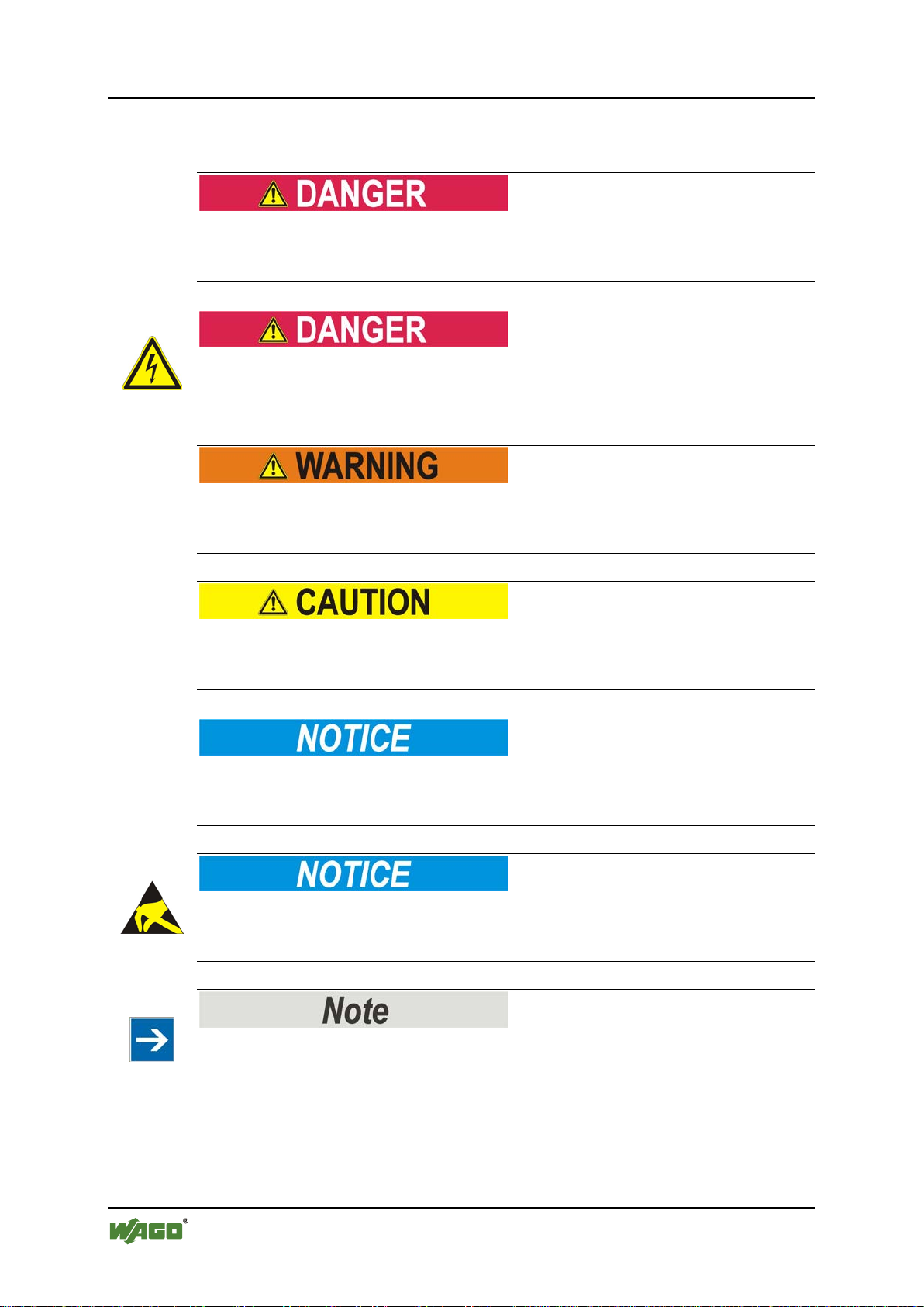
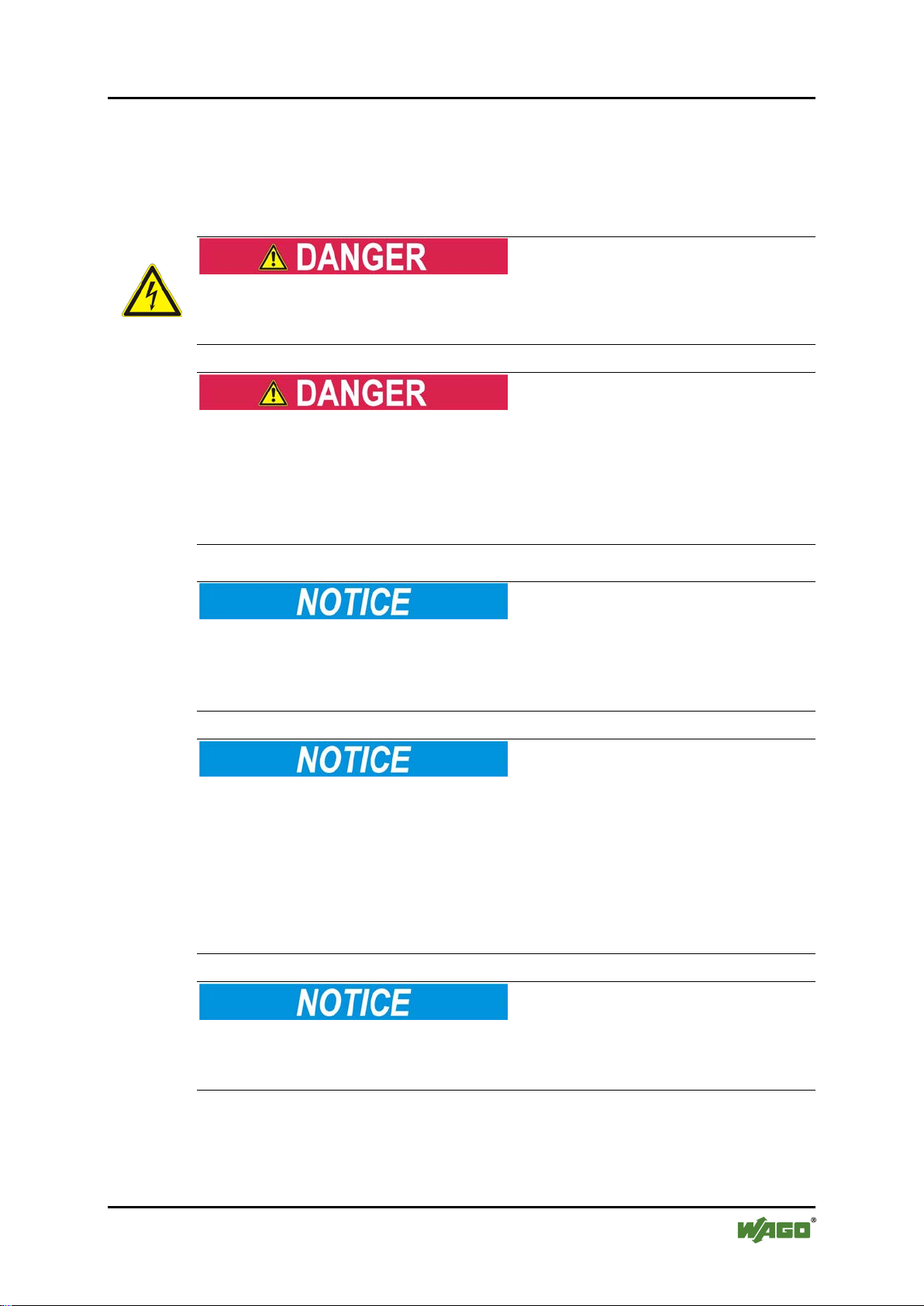
Pos: 12.4.1 /All e Serien (All g e meine Modul e) / Wi c htige Erläut erungen/ Sicherheits - und sonsti ge Hinwei se/Gefahr /Gefahr: _Warnung vor Person enschäden allgemein_ - Erläuterung @ 13\mod_1343309450020_21.doc @ 101029 @ @ 1
Personal Injury!
Indicates a high-risk, imminently hazardous situation which, if not avoided, will
result in death or serious injury.
Pos: 12.4.2 /All e Serien (All g e meine Modul e) / Wi c htige Erläut erungen/ Si c h er h ei ts - und sonstig e Hinweis e/Gefahr /G ef ahr: _Warn u ng vor Personens ch äden durch el e kt r i sc h e n St r o m _ - Erläuterung @ 13\mod_1343309694914_21.doc @ 101030 @ @ 1
Personal Injury Caused by Electric Current!
Indicates a high-risk, imminently hazardous situation which, if not avoided, will
result in death or serious injury.
Pos: 12.4.3 /All e Serien (All g e meine Modul e) / Wi c htige Erläut erungen/ Si c h er h ei ts - und sonstig e Hinweis e/Warnung /Warnung: _Warnung vor Perso nenschäd en allgemei n_ - Erläuterung @ 13\mod_1343309877041_21.doc @ 101035 @ @ 1
Personal Injury!
Indicates a moderate-risk, potentially hazardous situation which, if not avoided,
could result in death or serious injury.
Pos: 12.4.4 /All e Serien (All g e meine Modul e) / Wi c htige Erläut erungen/ Si c h er h ei ts - und sonstig e Hinweis e/Vorsic ht/Vorsicht : _Warnung vor Pers onenschä den allgemei n_ - Erläu ter ung @ 13\mod_1343310028762_21.do c @ 101038 @ @ 1
Personal Injury!
Indicates a low-risk, potentially hazardous situation which, if not avoided, may
result in minor or moderate injury.
Pos: 12.4.5 /Alle Seri en (Allge meine Mod ule)/Wichti ge Erläut erungen/Si cherheits- und sonstige Hinwe ise/Achtung/Achtung: _Warnung vor Sachs chäden allgemein_ - Erläuterung @ 13\mod_1343310134623_21.doc @ 101 041 @ @ 1
Damage to Property!
Indicates a potentially hazardous situation which, if not avoided, may result in
damage to property.
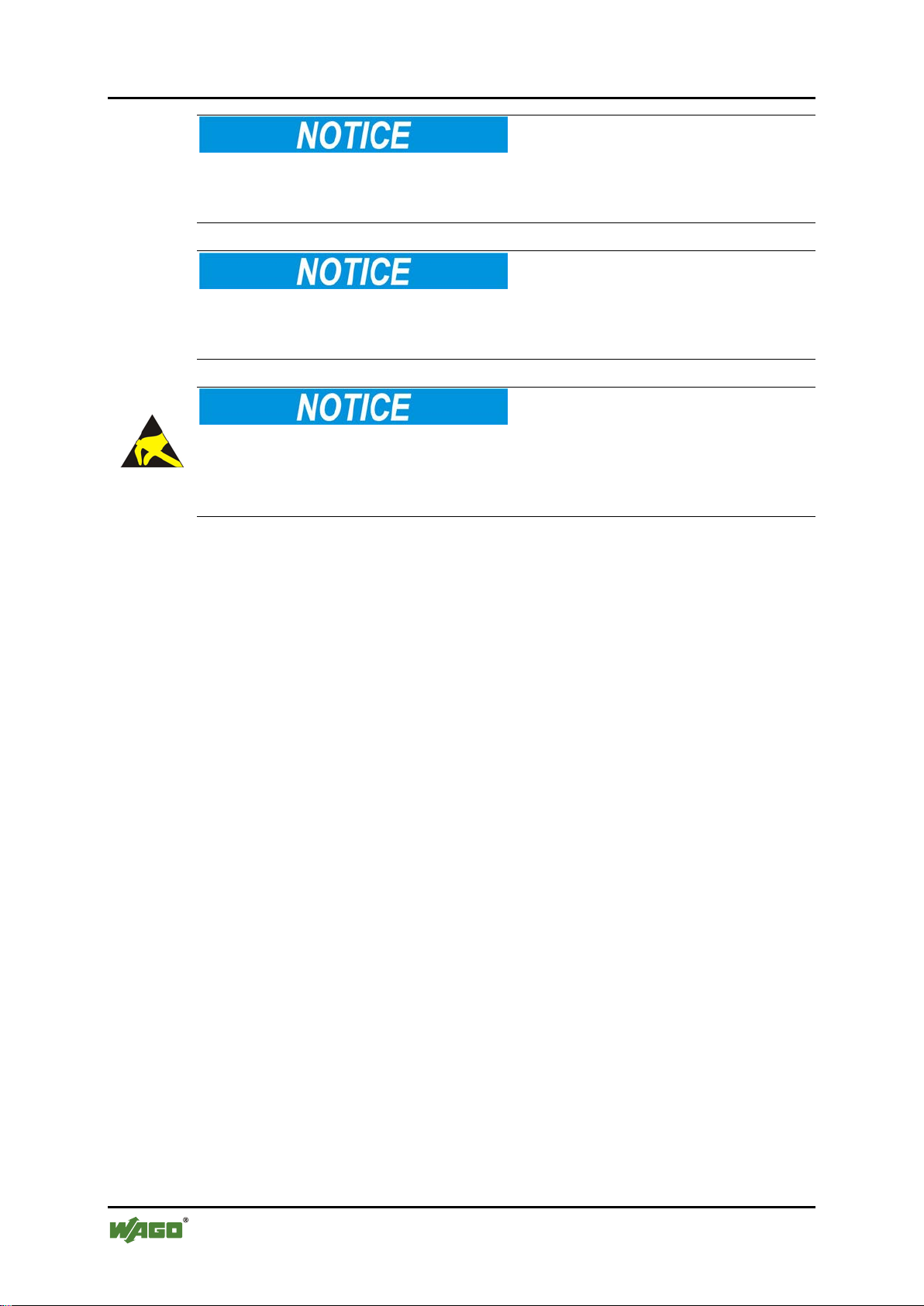
Pos: 12.4.6 /All e Serien (All g e meine Modul e) / Wi c htige Erläut erungen/Sicherheits- und sonstige Hi nweise/Ach tung/Ach tung: _War nung vor S achschäd en durch el ektrostatis che Auflad ung_ - Erläuterung @ 13\mod_1343310227702_21.doc @ 101044 @ @ 1
Damage to Property Caused by Electrostatic Discharge (ESD)!
Indicates a potentially hazardous situation which, if not avoided, may result in
damage to property.
Pos: 12.4.7 /All e Serien (All g e meine Modul e) / Wi c htige Erläut erungen/ Si c h er h ei ts - und sonstige Hinweise/Hinweis/Hinweis: _Wichtiger Hinweis allgemein_ - Eräuterung @ 13\mod_1343310326906_21.doc @ 101047 @ @ 1
Important Note!
Indicates a potential malfunction which, if not avoided, however, will not result in
damage to property.
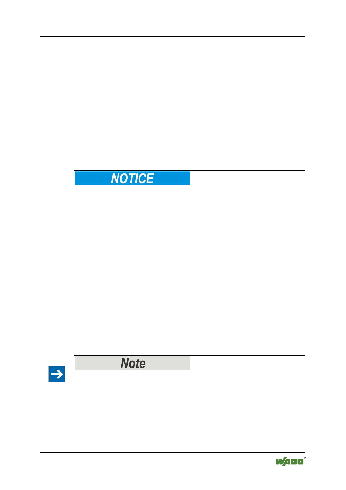
Pos: 12.4.8 /All e Serien (All g e meine Modul e) / Wi c htige Erläut erungen/ Si c h er h ei ts - und sonstig e Hinweis e/Infor mation/Infor mation: _Wei tere Infor mation allg em ei n_ - Erläuterung @ 13\mod_1343310439814_21.doc @ 101051 @ @ 1
Manual
Version 1.2.0
Page 7
WAGO-I/O-SYSTEM 750 Notes about this Documentation 7
750-512 2DO 230V AC 2.0A/ Relay 2NO
Additional Information:
Refers to additional information which is not an integral part of this
documentation (e.g., the Internet).
Pos: 12.5 /Dokumentation allgemein/Gli ederungs elemente/---Sei tenwechs el--- @ 3\mod_1221108045078_0.doc @ 21810 @ @ 1
Manual
Version 1.2.0
Page 8
8 Notes about this Documentation WAGO-I/O-SYSTEM 750
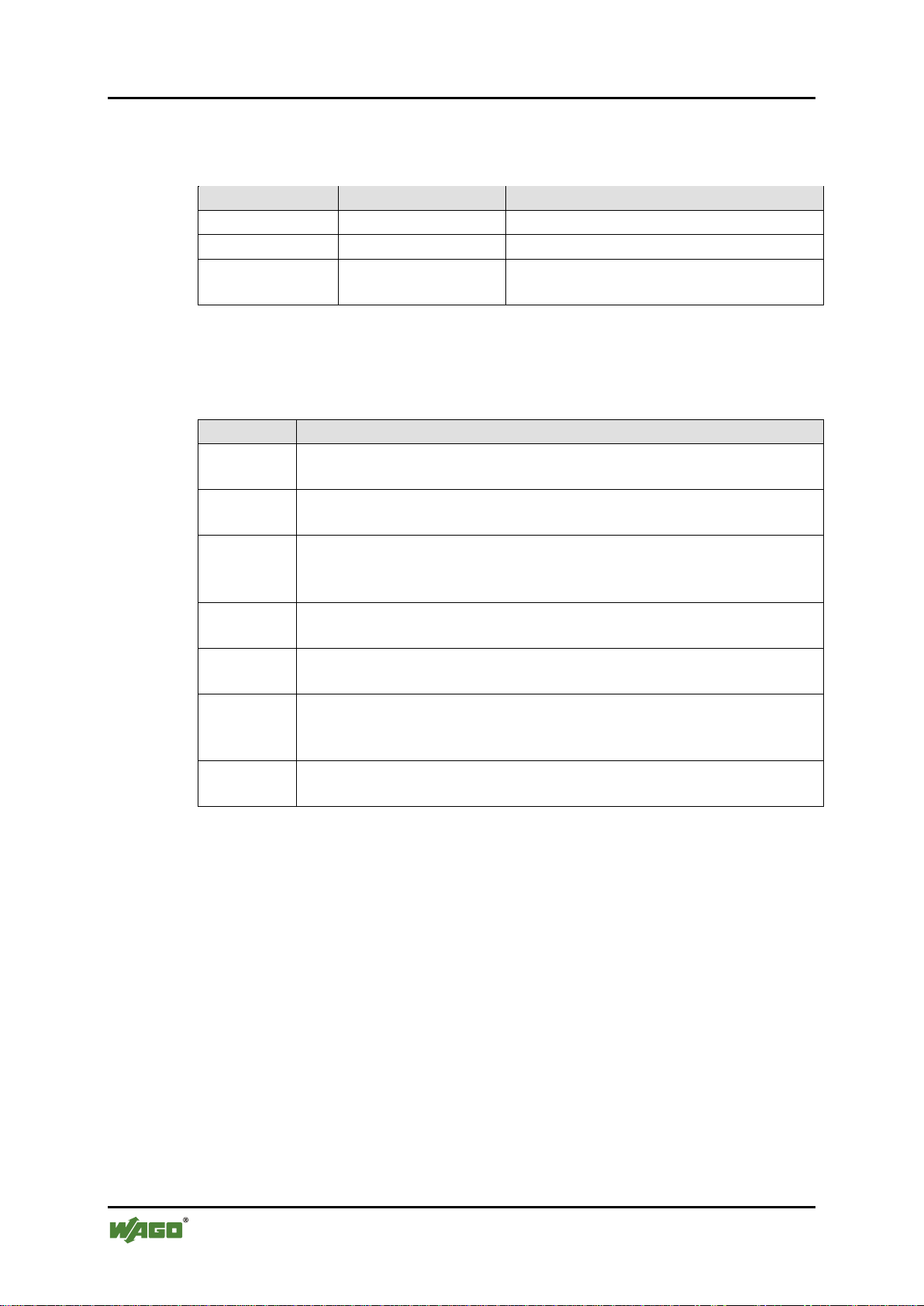
Table 1: Number notation
Number code
Example
Note
Decimal
100
Normal notation
Hexadecimal
0x64
C notation
Binary
'100'
'0110.0100'
In quotation marks, nibble separated with
dots (.)
Table 2: Font conventions
Font type
Indicates
italic
Names of paths and data files are marked in italic-type.
e.g.: C:\Programme\WAGO-I/O-CHECK
Menu
Menu items are marked in bold letters.
e.g.: Save
>
A greater-than sign between two names means the selection of a
e.g.: File > New
Input
Designation of input or optional fields are marked in bold letters,
e.g.: Start of measurement range
“Value”
Input or selective values are marked in inverted commas.
e.g.: Enter the value “4 mA” under Start of measurement range.
[Button]
Pushbuttons in dialog boxes are marked with bold letters in square
e.g.: [Input]
[Key]
Keys are marked with bold letters in square brackets.
e.g.: [F5]
750-512 2DO 230V AC 2.0A/ Relay 2NO
Pos: 12.6 /Al le Serie n (Allgemei ne Module) /Hinweis e zur Doku mentation/ Zahlensys teme @ 3\mod_1221059454015_21.doc @ 21711 @ 2 @ 1
1.4 Number Notation
Pos: 12.7 /Al le Serie n (Allgemei ne Module) /Hinweis e zur Doku mentation/ Schriftko nventione n @ 3\mod_1221059521437_21.d oc @ 21714 @ 2 @ 1
1.5 Font Conventions
Pos: 13 /Dokum e nt a ti o n al l g e mein/Glie der ungselem en te/---Seiten wechsel--- @ 3\mod_1221108045078_0.doc @ 21810 @ @ 1
menu item from a menu.
brackets.
Manual
Version 1.2.0
Page 9

WAGO-I/O-SYSTEM 750 Important Notes 9
750-512 2DO 230V AC 2.0A/ Relay 2NO
Pos: 14 /All e Serien ( Allgemeine Module)/Ü berschrift en für al le Serien/ Wichtige Er läu terungen / Wi c h ti g e Erläuterung en - Übersc hr i ft 1 @ 4\ mod_1241428899156_21.doc @ 32170 @ 1 @ 1
2 Important Notes
Pos: 15.1 /Al le Serie n (Allgemei ne Module) /Wichtig e Erläuteru ngen/Einl eitung Wic htige Erlä uterunge n @ 3\mod_1221059818031_21.d oc @ 21717 @ @ 1
This section includes an overall summary of the most important safety
requirements and notes that are mentioned in each individual section. To protect
your health and prevent damage to devices as well, it is imperative to read and
carefully follow the safety guidelines.
Pos: 15.2 /Al le Serie n (Allgemei ne Module) /Überschr iften für alle Serien /Wichtig e Erläuter ungen/Recht liche Gr undlagen - Ü b er sc hrift 2 @ 3\mod_1221060626343_21.doc @ 21726 @ 2 @ 1
2.1 Legal Bases
Pos: 15.3 /Al le Serie n (Allgemei ne Module) / Wichtige Er l ä ut er u ngen/Änd er u ngsvorbehal t - Überschr ift 3 und I nhalt @ 3\ mod_1221060036484_21.doc @ 21720 @ 3 @ 1
2.1.1 Subject to Changes
WAGO Kontakttechnik GmbH & Co. KG reserves the right to provide for any
alterations or modifications that serve to increase the efficiency of technical
progress. WAGO Kontakttechnik GmbH & Co. KG owns all rights arising from
the granting of patents or from the legal protection of utility patents. Third-party
products are always mentioned without any reference to patent rights. Thus, the
existence of such rights cannot be excluded.
Pos: 15.4 /Serie 750 (WAGO-I/O-SYSTEM)/ Wi c ht i g e Er l ä ut erungen/P er s onalquali fi kation 750- xxxx @ 3\mod_1224061208046_21.doc @ 24063 @ 3 @ 1
2.1.2 Personnel Qualifications
All sequences implemented on Series 750 devices may only be carried out by
electrical specialists with sufficient knowledge in automation. The specialists
must be familiar with the current norms and guidelines for the devices and
automated environments.
All changes to the coupler or controller should always be carried out by qualified
personnel with sufficient skills in PLC programming.
Pos: 15.5 /Serie 750 (WAGO-I/O-SYSTEM)/ Wi c ht i g e Er l ä ut erungen/B es timmungs g e mäße Verwen d ung 7 50- xxxx @ 3\mod_1224064151234_21.d oc @ 24070 @ 3 @ 1
2.1.3 Use of the 750 Series in Compli anc e wit h Unde rlying Provisions
Couplers, controllers and I/O modules found in the modular WAGO-I/OSYSTEM 750 receive digital and analog signals from sensors and transmit them
to the actuators or higher-level control systems. Using programmable controllers,
the signals can also be (pre-) processed.
The components have been developed for use in an environment that meets the
IP20 protection class criteria. Protection against finger injury and solid impurities
up to 12.5 mm diameter is assured; protection against water damage is not
ensured. Unless otherwise specified, operation of the components in wet and
dusty environments is prohibited.
Operating 750 Series components in home applications without further measures
is only permitted if they meet the emission limits (emissions of interference)
according to EN 61000-6-3. You will find the relevant information in the section
on "WAGO-I/O-SYSTEM 750" "System Description" "Technical Data" in
the manual for the used fieldbus coupler/controller.
Manual
Version 1.2.0
Page 10

10 Important Notes WAGO-I/O-SYSTEM 750
750-512 2DO 230V AC 2.0A/ Relay 2NO
Appropriate housing (per 94/9/EG) is required when operating the WAGO-I/OSYSTEM 750 in hazardous environments. Please note that a prototype test
certificate must be obtained that confirms the correct installation of the system in
a housing or switch cabinet.
Pos: 15.6 /Al le Serie n (Allgemei ne Module) /Wichtig e Erläuteru ngen/Tec hnischer Zu stand der Geräte - Üb erschrift 3 und Inhal t @ 3\mod_1221060446109_21.doc @ 21723 @ 3 @ 1
2.1.4 Technical Condition of Spec ified Devices
The components to be supplied Ex Works, are equipped with hardware and
software configurations, which meet the individual application requirements.
WAGO Kontakttechnik GmbH & Co. KG will be exempted from any liability in
case of changes in hardware or software as well as to non-compliant usage of
components.
Please send your request for modified and new hardware or software
configurations directly to WAGO Kontakttechnik GmbH & Co. KG.
Pos: 15.7 /Dokumentation allgemein/Gliederungselemente/---Seitenwechsel--- @ 3\mod_1221108045078_0.doc @ 21810 @ @ 1
Manual
Version 1.2.0
Page 11
WAGO-I/O-SYSTEM 750 Important Notes 11
750-512 2DO 230V AC 2.0A/ Relay 2NO
Pos: 15.8 /All e Ser i e n ( Al l g e mei ne Module)/ Ü berschrift en für alle Ser i en / Wichtige Er l äu ter ungen/Sic herheitshi nweise - Üb er s c hr i f t 2 @ 6\ mod_12601802999 87_21.doc @ 46724 @ 2 @ 1
2.2 Safety Advice (Precautions)
Pos: 15.9 /Al le Serie n (Allgemei ne Module) / Wichtige Erl ä uterunge n/ Si c h er h ei t s- und sonstig e Hinwei se/Einlei tung Sicher heitshin weise Hard ware @ 6\mod_1260180170493_21.doc @ 46720 @ @ 1
For installing and operating purposes of the relevant device to your system the
following safety precautions shall be observed:
Pos: 15.10. 1 /Alle Ser ien (Allge meine Mo dule)/Wich tige Erläu terungen/Si cherheits - und sonsti ge Hinwei se/Gefahr/ Gefahr: N icht an Ger äten unter Spannung arbeite n! @ 6\mod_1260180365327_21.d oc @ 46727 @ @ 1
Do not work on components while energized!
All power sources to the device shall be switched off prior to performing any
installation, repair or maintenance work.
Pos: 15.10. 2 /Serie 75 0 (WAGO-I/O- SYSTEM)/ Wichtige Er läuterung en/Sicher heits- und sonstige Hinweise/Gefahr/Gefahr: Einbau 07 50-xxxx nur in Gehäusen, Schränken oder elektrischen Betriebsräumen! @ 6\mod_1260180556692_21.doc @ 46731 @ @ 1
Installation only in appropriate housings, cabinets or in electrical operation
rooms!
The WAGO-I/O-SYSTEM 750 and its components are an open system. As such,
install the system and its components exclusively in appropriate housings,
cabinets or in electrical operation rooms. Allow access to such equipment and
fixtures to authorized, qualified staff only by means of specific keys or tools.
Pos: 15.10. 3 /Alle Ser ien (Allge meine Mo dule)/Wich tige Erläu terungen/Si cherheits - und sonsti ge Hinwei se/Gefahr/ Gefahr: U nfallverh ütungsvors c hriften beac ht en! @ 6\mod_1260180657000_21.doc @ 46735 @ @ 1
Pos: 15.10. 4 /Alle Ser ien (Allge meine Mo dule)/Wich tige Erläu terungen/Si cherheits - und sonsti ge Hinwei se/Gefahr/ Gefahr: A uf normg erechten Ans chluss ac hten! @ 6\ mod_1260180753479_21.doc @ 46739 @ @ 1
Pos: 15.11. 1 /Alle Ser ien (Allge meine Mo dule)/Wich tige Erläu terungen/Si cherheits - und sonstige Hinweis e/Achtung/Achtung: Defekte oder beschädigte Geräte austaus chen! @ 6\mod_1260180857358_21.doc @ 46743 @ @ 1
Replace defective or damaged devices!
Replace defective or damaged device/module (e.g., in the event of deformed
contacts), since the long-term functionality of device/module involved can no
longer be ensured.
Pos: 15.11. 2 /Alle Ser ien (Allge meine Mo dule)/Wich tige Erläu terungen/Si cherheits - und sonsti ge Hinwei se/Achtu ng/Achtung: Geräte vor krieche nden und is olierend en Stoffen s chützen! @ 6\mod_1260181036216_21.doc @ 46747 @ @ 1
Protect the components against materials having seeping and insulating
properties!
The components are not resistant to materials having seeping and insulating
properties such as: aerosols, silicones and triglycerides (found in some hand
creams). If you cannot exclude that such materials will appear in the component
environment, then install the components in an enclosure being resistant to the
above-mentioned materials. Clean tools and materials are imperative for handling
devices/modules.
Pos: 15.11. 3 /Alle Ser ien (Allge meine Mo dule)/Wich tige Erläu terungen/Si cherheits - und sonsti ge Hinwei se/Achtu ng/Achtung: Reinigu ng nur mit z ulässige n Materiali en! @ 6\mod_1260181203293_21.doc @ 46751 @ @ 1
Cleaning only with permitted materials!
Clean soiled contacts using oil-free compressed air or with ethyl alcohol and
leather cloths.
Pos: 15.11. 4 /Alle Ser ien (Allge meine Mo dule)/Wich tige Erläu terungen/Si cherheits - und sonsti ge Hinwei se/Achtu ng/Achtung: Kein Ko ntaktspray verwenden! @ 6\mod_1260181290808_21.doc @ 46755 @ @ 1
Manual
Version 1.2.0
Page 12
12 Important Notes WAGO-I/O-SYSTEM 750
750-512 2DO 230V AC 2.0A/ Relay 2NO
Do not use any contact spray!
Do not use any contact spray. The spray may impair contact area functionality in
connection with contamination.
Pos: 15.11. 5 /Alle Ser ien (Allge meine Mo dule)/Wich tige Erläu terungen/Si cherheits - und sonsti ge Hinwei se/Achtu ng/Achtung: Verpolung vermeide n! @ 6\mod_1260184045744_21.doc @ 46767 @ @ 1
Do not reverse the polarity of connection lines!
Avoid reverse polarity of data and power supply lines, as this may damage the
devices involved.
Pos: 15.11. 6 /Alle Ser ien (Allge meine Mo dule)/Wich tige Erläu terungen/Si cherheits - und sonsti ge Hinwei se/Achtu ng/Achtung: Elektrost atische E ntladung vermeiden! @ 6\mod_1260181364729_21.doc @ 46759 @ @ 1
Avoid electrostatic discharge!
The devices are equipped with electronic components that you may destroy by
electrostatic discharge when you touch. Pay attention while handling the devices
to good grounding of the environment (persons, job and packing).
Pos: 16 /Dokum e nt a ti o n al l g e mein/Glie der ungselem en te/---Seiten wechsel--- @ 3\mod_1221108045078_0.doc @ 21810 @ @ 1
Manual
Version 1.2.0
Page 13
WAGO-I/O-SYSTEM 750 Device Description 13
750-512 2DO 230V AC 2.0A/ Relay 2NO
Pos: 17 /All e Serien ( Allgemeine Module)/Ü berschrift en für al le Serien/G erätebesc hreibung /Gerätebes chreibung - Ü berschrif t 1 @ 3\mod_1233756084656_21.doc @ 27096 @ 1 @ 1
3 Device Description
Pos: 18.1 /Serie 750 (WAGO-I/O-SYSTEM)/G er ätebeschr ei bung/Einl ei t ung/Anw en du ng /DO/Anw en d ung 750-05xx DO Rel ais @ 5\mod_1246611276875_21 .doc @ 36561 @ @ 1
The 750-512 Digital Output Module transmits binary control signals from the
automation device to the connected actuators (e.g., solenoid valves, contactors,
transmitters, relays or other electrical loads).
Pos: 18.2 /Serie 750 (WAGO-I/O-SYSTEM)/G erätebesc hreibung/Ei nleitung /I/O-Beschr eibung/DO /I/O-Besc hreibung 7 50-05xx 2 DO 3-Leiter (DO, N un d PE) @ 5\mod_1246610806328_21.doc @ 36557 @ @ 1
The module has two output channels. Two actuators with ground (earth) wire may
be directly connected to signal output DO 1, N and PE (earth potential) or signal
Pos: 18.3 /Serie 750 (WAGO-I/O-SYSTEM)/G erätebesc hreibung/Ei nleitung /I/O-Beschr eibung/All gemein/V erweis auf Kapitel " Anschlüss e" @ 8\mod_1276775378035_21.doc @ 57956 @ @ 1
Pos: 18.4 /Serie 750 (WAGO-I/O-SYSTEM)/G erätebesc hreibung/Ei nleitung /I/O-Beschr eibung/All gemein/V erweis auf Kapitel " Geräte ans chließen" > "Anschlus sbeispiel (e)" @ 5\ mod_1246015203281_21.doc @ 36298 @ @ 1
Pos: 18.5 /Serie 750 (WAGO-I/O-SYSTEM)/ Wi c ht i g e Er l ä ut erungen/Si c herheits- und sonstige Hinweise/Achtung/Ach tung: DO Induktionsspannungsbegrenzung R elais @ 5\mod_1247031985231_21.doc @ 36766 @ @ 1
output DO 2, N and PE.
The assignment of the connections is described in the "Connections" section.
Connection examples are shown in section "Connecting Devices" "Connection
Examples".
Inductive loads must be dampened!
For the protection of relay coils and contacts, inductive loads must be dampened
with an effective protection circuit!
Examples of protection circuits can be seen in the section "Protective Circuits for
Contacts of Relay Modules".
Pos: 18.6 /Serie 750 (WAGO-I/O-SYSTEM)/G erätebesc hreibung/Ei nleitung /I/O-Beschr eibung/DO /I/O-Besc hreibung 7 50-0512 Schl ieß er-Relais @ 5\mod_1246868974281_21.doc @ 36625 @ @ 1
Each module is equipped with one non-floating make contact relay per channel,
i.e. the fieldside voltage supply (230 V AC or 30 V DC) is connected to each
terminal of the relay and is fed in via the internal power jumper contacts of an
adjacent supply module.
By closing a relay, the field power applied is switched to the second relay
connection of signal output DO1 or DO2.
Pos: 18.7 /Serie 750 (WAGO-I/O-SYSTEM)/G erätebesc hreibung/Ei nleitung /I/O-Beschr eibung/DO /I/O-Besc hreibung 7 50-05xx Ansteuerung der Relais (Interne Systemspannung) @ 5\mod_1246861676649_21 .doc @ 36599 @ @ 1
The internal system voltage is used to trigger the relays.
Pos: 18.8 /Serie 750 (WAGO-I/O-SYSTEM)/G erätebesc hreibung/Ei nleitung /LED-Anzei ge/LED Zu stand Relai s @ 5\mod_1246862048946_21.doc @ 36603 @ @ 1
Pos: 18.9 /Serie 750 (WAGO-I/O-SYSTEM)/G erätebesc hreibung/Ei nleitung /LED-Anzei g e/ Verweis auf Ka pi t el "Anzeigeel emente" @ 5\ mod_1246010525000_21.doc @ 36194 @ @ 1
The switching status of the two relays is indicated via green status LEDs.
The meaning of the LEDs is described in the “Display Elements” section.
Pos: 18.10 / Serie 750 ( WAGO-I/O-SY STEM)/Wi chtige Erl äuterung en/Sicherhei ts- und son stige Hin weise/Hin weis/Hinwei s: Einspei seklemme für Versor gung ungl eich 24 V ei nsetzen @ 5\mod_1247032609340_21.doc @ 36784 @ @ 1
Use additional supply module!
Use an additional supply module if I/O modules require a field supply not equal to
24 V DC. Insert the supply module in front of the module that requires the
different supply.
Pos: 18.11 / Serie 750 ( WAGO-I/O-SY STEM)/G er ät e beschreib ung / Einleitung /Versorg u ng /Versorg ung AC 230 V / DC 30 V, 0 V, Er d e üb er Lei s t u ngskonta kt e @ 5\ mod_1246869265656_21.doc @ 36628 @ @ 1
The I/O module receives the AC 230V or DC 30V potential for the field level
from an upstream I/O module or from the fieldbus coupler/controller via the
Manual
Version 1.2.0
Page 14

14 Device Description WAGO-I/O-SYSTEM 75 0
750-512 2DO 230V AC 2.0A/ Relay 2NO
power contacts used as blade contacts. It then provides this potential to
subsequent I/O modules via the power contacts used as spring contacts.
Pos: 18.12 / Serie 750 ( WAGO-I/O-SY STEM)/Wic htige Erläu terungen /Sicherhei ts- und sons tige Hinw eise/Acht ung/Achtung : Maximal er Strom Leistungs kontakte 1 0 A @ 3\mod_1226499143500_21.doc @ 25029 @ @ 1
Do not exceed maximum current via power contacts!
The maximum current to flow through the power contacts is 10 A.
Greater currents can damage the power contacts.
When configuring the system, ensure that this current is not exceeded. If
exceeded, an additional potential feed module must be used.
Pos: 18.13 / Serie 750 ( WAGO-I/O-SY STEM)/G erätebeschr eibung/Ei nleitung/ Versorgung /Anordnu ng unter Ber ücksichti gung der Leistungs kontakte bel iebig @ 3\ mod_1233756233468_21.doc @ 27099 @ @ 1
With consideration of the power jumper contacts, the individual modules can be
arranged in any combination when configuring the fieldbus node. An arrangement
in groups within the group of potentials is not necessary.
Pos: 18.14 / Serie 750 ( WAGO-I/O-SY STEM)/G er ät e beschreib ung / Einleitung /Einsatz b er ei c h/Einsat zb er ei c h 750-xxxx alle Koppl er/Controll er ohne Ei nschrän kung @ 3\mod_1232541691906_21.doc @ 26522 @ @ 1
The I/O module 750-512 can be used with all fieldbus couplers/controllers of the
WAGO-I/O-SYSTEM 750.
Pos: 19 /Dokum e nt a ti o n al l g e mein/Glie der ungselem en te/---Seiten wechsel--- @ 3\mod_1221108045078_0.doc @ 21810 @ @ 1
Manual
Version 1.2.0
Page 15

WAGO-I/O-SYSTEM 750 Device Description 15
Table 1: Caption acc. to figure „Connections““
No.
Designation
Description
Details see chapter
Marking possibility with
Mini-WSB
„Technical manual“ >
„Display elements
„Mounting“ > „Mounting
device“
CAGE CLAMP®-supply DO
V, N and ground.
Power contacts AC 230 V /
DC 30 V
„Technical manual “ >
„Connections“
„Mounting“ > „Mounting
device“
„Technical manual “ >
„Connections “
„Technical manual “ >
„Connections“
750-512 2DO 230V AC 2.0A/ Relay 2NO
Pos: 20 /All e Serien ( Allgemeine Module)/Ü berschrift en für al le Serien/G erätebesc hreibung /Ansicht - Ü berschrift 2 @ 4\mod_1240984217343_21.doc @ 31958 @ 2 @ 1
3.1 View
Pos: 21 /Ser ie 750 ( WAGO-I/O-SYST EM)/Gerät ebeschrei bung/Ansic ht/Digital ausgangs klemmen/A nsicht 750- 0512 @ 10\mod_1298370 459642_21.doc @ 69783 @ @ 1
Figure 1: View
Pos: 22 /Dokumentation allgemein/G li e derungsel e m en te /---Seitenwec hsel--- @ 3\mod_1221108045078_0.doc @ 21810 @ @ 1
1 ---
2 A, C Status-LEDs
3 --- Data contacts
4 1 … 8
1, DO 2, AC 230 V / DC 30
5 ---
6 --- Interlock links
7 --- Power contacts 0 V
8 --- Power contacts ground
---
„Technical manual “ >
„Connections“
Manual
Version 1.2.0
Page 16

16 Device Description WAGO-I/O-SYSTEM 75 0
750-512 2DO 230V AC 2.0A/ Relay 2NO
Pos: 23 /All e Serien ( Allgemeine Module)/Ü berschrift en für al le Serien/G erätebesc hreibung /Anschlüss e - Übersc hr if t 2 @ 4\ mod_12409842626 56_21.doc @ 31961 @ 2 @ 1
3.2 Connectors
Pos: 24 /Ser ie 750 ( WAGO-I/O-SYSTEM)/Gerätebeschreibung/Anschlüsse/Datenkontakte/Klemmenbus - Überschrift 3 @ 6\ mod_1256294684083_21.doc @ 43660 @ 3 @ 1
3.2.1 Data Contacts/Internal Bus
Pos: 25.1 /Serie 750 (WAGO-I/O-SYSTEM)/G erätebesc hreibung/A nschlüsse/Datenkontakte @ 3\mod_1231771259187_21.doc @ 26002 @ @ 1
Communication between the coupler/controller and the I/O modules as well as the
system supply of the I/O modules is carried out via the internal bus. It is
comprised of 6 data contacts, which are available as self-cleaning gold spring
contacts.
Figure 2: Data contacts
Pos: 25.2 /Serie 750 (WAGO-I/O-SYSTEM)/Wic hti g e Er l ä ut erungen/Si c herheits- und sonstige Hi n w ei s e/Achtung /Ac htung: Bus kl emmen nicht a uf Gol dfederk on t a kt e leg e n! @ 7\mod_1266318463636_21.doc @ 50695 @ @ 1
Do not place the I/O modules on the gold spring contacts!
Do not place the I/O modules on the gold spring contacts in order to avoid soiling
or scratching!
Pos: 25.3 /Serie 750 (WAGO-I/O-SYSTEM)/ Wi c ht i g e Er l ä ut erungen/Si cherheits - und sonstige Hinweise/Achtung/Achtung: ESD - Auf gute Erdung der Umgebu ng achten! @ 7\mod_1266318538667_21 .doc @ 50708 @ @ 1
Ensure that the environment is well grounded!
The modules are equipped with electronic components that may be destroyed by
electrostatic discharge. When handling the modules, ensure that the environment
(persons, workplace and packing) is well grounded. Avoid touching conductive
components, e.g. data contacts.
Pos: 26 /Dokum e nt a ti o n al l g e mein/Glie der ungselem en te/---Seiten wechsel--- @ 3\mod_1221108045078_0.doc @ 21810 @ @ 1
Manual
Version 1.2.0
Page 17

WAGO-I/O-SYSTEM 750 Device Description 17
Table 3: Power jumper contacts
Connection
Type
Number
Function
750-512 2DO 230V AC 2.0A/ Relay 2NO
Pos: 27 /Ser ie 750 ( WAGO-I/O-SYST EM)/Gerät ebeschrei bung/Ansc hlüsse/Leis tungskont akte/Feld versorgung - Überschr i ft 3 @ 6\ mod_1256294692864_21.doc @ 43664 @ 3 @ 1
3.2.2 Power Jumper Contacts/ Field Supply
Pos: 28.1 /Serie 750 (WA GO-I/O-SYSTEM ) / Wi c htige Erläut erungen/Si c herheits- und sonstig e Hinweis e/Vorsic ht/Vorsicht : Verletz ungsgefahr durch sch arfkantig e Messerko ntakte! @ 6\mod_1256193279401_21.doc @ 43414 @ @ 1
Risk of injury due to sharp-edged male contacts!
The male contacts are sharp-edged. Handle the module carefully to prevent injury.
Pos: 28.2 /Serie 750 (WAGO-I/O-SYSTEM)/Ger ätebeschr eibung/Ans chlüsse/L eistungs kontakte 3 LK (Messer /Feder) @ 7\mod_1266318232808_21.doc @ 50691 @ @ 1
The I/O module 750-512 has 3 self-cleaning power jumper contacts that supply
and transmit power for the field side. The contacts on the left side of the I/O
module are designed as male contacts and the contacts on the right side as spring
contacts.
Fig 3: Power jumper
contacts
Pos: 28.3 /Serie 750 (WAGO-I/O-SYSTEM)/ Wi c ht i g e Er l ä ut erungen/Si c herheits- und sonstige Hinweise/Achtung/Achtung: Maximaler Strom Leistungskontakte 10 A @ 3\mod_1226499143500_21.doc @ 25029 @ @ 1
Do not exceed maximum current via power contacts!
The maximum current to flow through the power contacts is 10 A.
Greater currents can damage the power contacts.
When configuring the system, ensure that this current is not exceeded. If
exceeded, an additional potential feed module must be used.
Infeed of the field
1 Blade cont act 3
supply voltage
(UV, 0 V and earth)
Forwarding of the
2 Spring contact 3
field supply voltage
(UV, 0 V and earth)
Pos: 29 /Dokum e nt a ti o n al l g e mein/Glie der ungselem en te/---Seiten wechsel--- @ 3\mod_1221108045078_0.doc @ 21810 @ @ 1
Manual
Version 1.2.0
Page 18

18 Device Description WAGO-I/O-SYSTEM 75 0
Table 4: Connectors
Designati
on
Output DO 1: Field supply
DC 30 V
Power
contacts
Power
contacts
Power
contacts
750-512 2DO 230V AC 2.0A/ Relay 2NO
Pos: 30 /Ser ie 750 ( WAGO-I/O-SYST EM)/Gerät ebeschrei bung/Ansc hlüsse/CA GE CLAMP-An schlüsse - Ü berschrift 3 @ 6\mod_1256296337770_21.doc @ 43674 @ 3 @ 1
3.2.3 CAGE CLAMP® Connections
Pos: 31 /Ser ie 750 ( WAGO-I/O-SYST EM)/Gerät ebeschrei bung/Ansc hlüsse/Dig italausgang sklemme n/ Anschlüss e 75 0-0512 @ 10\mod_1298374547434_21.doc @ 69887 @ @ 1
Pos: 32 /Dokum e nt a ti o n al l g e mein/Glie der ungselem en te/---Seiten wechsel--- @ 3\mod_1221108045078_0.doc @ 21810 @ @ 1
Figure 4: Connectors
Connector Channel
Function
1 1 DO 1 Output DO 1: Signal vo lta ge
5 2 DO 2 Output DO 2: Signal vo lta ge
6 2
AC 230 V
DC 30 V
AC 230 V
7 2 N Output DO 2: N
8 2 Earth Output DO 2: Earth
jumper
jumper
jumper
- +24 V Field supply 24 V
- 0 V Field supply 0 V
- Earth Field supply Earth
Manual
Version 1.2.0
Page 19

WAGO-I/O-SYSTEM 750 Device Description 19
Table 5: Display elements
Designation
750-512 2DO 230V AC 2.0A/ Relay 2NO
Pos: 33 /All e Serien ( Allgemeine Module)/Ü berschrift en für al le Serien/G erätebesc hreibung /Anzeigeel emente - Üb erschrift 2 @ 4\mod_1240984390875_21.doc @ 31964 @ 2 @ 1
3.3 Display Elements
Pos: 34 /Ser ie 750 ( WAGO-I/O-SYST EM)/Gerät ebeschreibung/Anzeigeelemente/Digitalausgangsklemm en/Anzeigeelemente 750-0512 @ 10\mod_1298371006175_21.doc @ 69835 @ @ 1
LED Channel
A 1
Figure 5: Displa y
elements
Pos: 35 /All e Serien ( Allgemeine Module)/Ü berschrift en für al le Serien/G erätebesc hreibung /Bedienel emente - Über schrift 2 @ 4\mod_1239191655456_21.doc @ 30439 @ 2 @ 1
C 2
3.4 Operating Elements
Pos: 36 /Ser ie 750 ( WAGO-I/O-SYST EM)/Ger ätebeschrei bung/Bedi enelement e/Bedienel emente B usklemme 7 50-xxxx nic ht vorhand en @ 4\mod_1236322031125_21.doc @ 28063 @ @ 1
The I/O module 750-512 has no operating elements.
Pos: 37 /Dokumentation allgemein/Gliederungs elemente/---Sei tenwechs el--- @ 3\mod_1221108045078_ 0.doc @ 21810 @ @ 1
State Function
off Output DO 1: Signal volta ge (0)
Status
DO 1
green Output DO 1: Signal voltage (1)
off Output DO 2: Signal voltage ( 0)
Status
DO 2
green Output DO 2: Signal voltage (1)
Manual
Version 1.2.0
Page 20

20 Device Description WAGO-I/O-SYSTEM 75 0
750-512 2DO 230V AC 2.0A/ Relay 2NO
Pos: 38 /Alle Seri en (Allge mei ne Module)/Ü ber s chriften für al l e S erien/Gerä tebeschr ei b u ng / Sc hematisch es Schaltbil d - Überschri f t 2 @ 4\mod_1240984441312_21.doc @ 31967 @ 2 @ 1
3.5 Schematic Diagram
Pos: 39 /Ser ie 750 ( WAGO-I/O-SYST EM ) / Gerätebes c hr ei bung/Sch e matische Sc hal tbilder/Di g i t alausgang s klemmen/Sc hematisch es Schaltbil d 750-0512 @ 10\mod_1298371082616_21.doc @ 69847 @ @ 1
Figure 6: Schematic d iagram
Pos: 40 /Dokum e nt a ti o n al l g e mein/Glie der ungselem en te/---Seiten wechsel--- @ 3\mod_1221108045078_0.doc @ 21810 @ @ 1
Manual
Version 1.2.0
Page 21

WAGO-I/O-SYSTEM 750 Device Description 21
Table 6: Technical data device
Width
12 mm
Height (from upper edge of 35 DIN rail)
64 mm
Depth
100 mm
Weight
ca. 55 g
Table 7: Technical data power supply
Current consumption
max.
(internal)
100 mA
Table 8: Technical data communication
Internal bit width
2 bits
Table 9: Technical data inputs
Number of outputs
2 make contacts
Switching voltage
(max.)
AC 250 V/DC 30 V
Switching power
500 VA/60 W
cosφ
max
= 0,4; L/R
max
= 7 ms
Switching current
(max.)
AC/DC 2 A
Switching current
(min.)
10 mA / 5 V DC
Switching rate
(max.)
30/min (at nominal load)
Pull-in time
(max.)
10 ms
Bounce time
typ.
1,2 ms
Drop-out time
max.
10 ms
Contact material
Silver alloy
Mechanical life
max.
2x10⁷ switching operations
Electrical life
min.
3x10⁵ (AC 2 A/250 V) or (DC 2 A/30V)
Isolation
1,5 kV
(field/system)*
Overvoltage category III
750-512 2DO 230V AC 2.0A/ Relay 2NO
Pos: 41 /Alle Ser i en (Allge mei ne Module)/Ü ber s chriften für al l e S erien/Gerä tebeschr ei b u ng / Tec hnische Dat en - Überschr ift 2 @ 3\ mod_1232967587687_21.doc @ 26924 @ 2 @ 1
3.6 Technical Data
Pos: 42 /Ser ie 750 ( WAGO-I/O-SYST EM)/Gerät ebeschrei bung/Tech nische Date n/Digitalausgangsklemmen/Technische Dat en 750-0512 @ 10\mod_1298385334380_21.doc @ 699 79 @ 3333 @ 1
3.6.1 Device Data
3.6.2 Power Supply
3.6.3 Communication
3.6.4 Outputs
eff.
*2,5 kV rated surge voltage;
Pos: 43 /Dokum e nt a ti o n al l g e mein/Glie der ungselem en te/---Seiten wechsel--- @ 3\mod_1221108045078_0.doc @ 21810 @ @ 1
Manual
Version 1.2.0
Page 22

22 Device Description WAGO-I/O-SYSTEM 75 0
Conformity Marking
TÜV 07 ATEX 554086 X
I M2 Ex d I Mb
II 3 D Ex tc IIIC T135°C Dc
Ambient temperature range:
0 °C ≤ T
a
≤ +60 °C
IECEx TUN 09.0001 X
Ex d I Mb
Ex tc IIIC T135°C Dc
Ambient temperature range:
0 °C ≤ T
a
≤ +60 °C
CULUS
ANSI/ISA 12.12.01
Class I, Div2 ABCD T4
750-512 2DO 230V AC 2.0A/ Relay 2NO
Pos: 44 /All e Serien ( Allgemeine Module)/Ü berschrift en für al le Serien/G erätebesc hreibung /Zulassung en - Übersc hr i ft 2 @ 3\ mod_1224055364109_21.doc @ 24030 @ 2 @ 1
3.7 Approvals
Pos: 45 /Ser ie 750 ( WAGO-I/O-SYST EM ) / Gerätebes c hr ei bung/Zul as s u ngen/Infor m at i on: Weiter e Inf ormatione n z u Zul assungen 750- xxxx @ 3\mod_1227190967156_21.doc @ 25221 @ @ 1
More Information about Approvals
Detailed references to the approvals are listed in the document "Overview
Approvals WAGO-I/O-SYSTEM 750", which you can find on the DVD
“AUTOMATION Tools and Docs” (order no. 0888-0412) or via the internet
under: www.wago.com Documentation WAGO-I/O-SYSTEM 750
System Description.
Pos: 46 /Ser ie 750 ( WAGO-I/O-SYST EM)/Gerät ebeschrei bung/Zulass ungen/All gemein/Zul assungen Busklem me 750-xxxx Al l g e mein, ohne Var i an tenangab e - Ei nleitung @ 4\ mod_1237460656921_21.doc @ 28643 @ @ 1
The following approvals have been granted to 750-512 I/O modules:
Pos: 47.1 /Al le Serie n (Allgemei ne Module) /Zulassu ngen/Stan dardzulass ungen/CE ( Konformit ätskennzei chnung) @ 3\mod_1224494777421_21.doc @ 24276 @ @ 1
Pos: 47.2 /Al le Serie n (Allgemei ne Module) /Zulassu ngen/Stan dardzulass ungen/cULus (UL508) @ 3\mod_1224 055013140_0.doc @ 24020 @ @ 1
Pos: 47.3 /Dokumentation allgemein/Gliederungselemente/------Leerzeile------ @ 3\mod_1224662755687_0.doc @ 24460 @ @ 1
Pos: 48 /Ser ie 750 ( WAGO-I/O-SYST EM)/Gerät ebeschrei bung/Zulass ungen/Ex /Zulassu ngen Buskl emme 750- xxxx Ex, ohne Vari antenangabe - Einleitung @ 4\mod_1237191218000_21.doc @ 28423 @ @ 1
The following Ex approvals have been granted to 750-512 I/O modules:
Pos: 49.1 /Al le Serie n (Allgemei ne Module) /Zulassu ngen/Ex-Zul assungen /TÜV ATEX/ TÜV 07 AT EX 554086 X: I M2 Ex d I Mb II 3 G Ex nA nC I IC T4 Gc I I 3 D Ex tc IIIC T135 °C Dc @ 14 \ mod_1362133489555_0.doc @ 113428 @ @ 1
Pos: 49.2 /Al le Serie n (Allgemei ne Module) /Zulassu ngen/Ex-Zul assungen /Ergänzung Zulässig er Umgebung stemper aturbereic h 0 °C <= Ta <= +60 °C @ 9\mod_1295605895541_21. doc @ 68610 @ @ 1
Pos: 49.3 /Alle Serien (Allgemeine Module)/Zu lassungen/Ex-Zulassungen/IEC E x (TÜ V N or d) /IECEx TUN 09. 0001 X: Ex d I Mb E x nA nC IIC T4 Gc Ex tc IIIC T13 5°C @ 14 \mod_1362133668858 _0.doc @ 113432 @ @ 1
CULUS
II 3 G Ex nA nC IIC T4 Gc
UL508
Ex nA nC IIC T4 Gc
Pos: 49.4 /Al le Serie n (Allgemei ne Module) /Zulassu ngen/Ex-Zul assungen /Ergänzung Zulässig er Umgebung stemper aturbereic h 0 °C <= Ta <= +60 °C @ 9\mod_1295605895541_21. doc @ 68610 @ @ 1
Pos: 49.5 /Al le Serie n (Allgemei ne Module) /Zulassu ngen/Ex-Zul assungen /cULus/cUL us (ANSI/I SA 12.12. 01) Class I, Div2 ABC D T4 @ 3\ mod_1224054791812_0.doc @ 24014 @ @ 1
Pos: 49.6 /Dokumentation allgemein/Gliederungselemente/------Leerzeile------ @ 3\mod_1224662755687_0.doc @ 24460 @ @ 1
Pos: 50 /Ser ie 750 ( WAGO-I/O-SYST EM ) / Gerätebes c hr ei bung/Zul as s u ngen/Schif f/Zulassu ngen Buskle mme 750-xxx x Schiff, ohne Variant enangabe - Einleitu ng @ 4\mod_1237190918453_21.doc @ 28420 @ @ 1
Pos: 51.1 /Al le Serie n (Allgemei ne Module) /Zulassu ngen/Schi ffszulassu ngen/ABS ( American Bureau of Shipping) @ 3\mod_1224055151062_0.doc @ 24023 @ @ 1
Pos: 51.2 /Al le Serie n (Allgemei ne Module) /Zulassu ngen/Schi ffszulassu ngen/BSH ( Bundesam t für Seesc hifffahrt und Hydrog raphie) @ 5\mod_1246341825156_21.doc @ 36334 @ @ 1
Pos: 51.3 /Al le Serie n (Allgemei ne Module) /Zulassu ngen/Schi ffszulassu ngen/BV (B ureau Veri tas) @ 3\mod_1224492116171 _0.doc @ 2 4220 @ @ 1
Pos: 51.4 /Al le Serie n (Allgemei ne Module) /Zulassu ngen/Schi ffszulassu ngen/DNV ( Det Nors ke Veritas) C lass B @ 3 \mod_1224492540562_0.doc @ 24224 @ @ 1
Manual
Version 1.2.0
The following ship approvals have been granted to 750-512 I/O modules:
ABS (American Bureau of Shipping)
Federal Maritime and Hydrographic Agency
BV (Bureau Veritas)
Page 23

WAGO-I/O-SYSTEM 750 Device Description 23
750-512 2DO 230V AC 2.0A/ Relay 2NO
DNV (Det Norske Veritas) Class B
Pos: 51.5 /Al le Serie n (Allgemei ne Module) /Zulassu ngen/Schi ffszulassu ngen/GL (G ermanisch er Lloyd) C at. A, B, C , D (EMC 1) @ 3\mod_1224492724484_0.doc @ 24228 @ @ 1
GL (Germanischer Lloyd) Cat. A, B, C, D (EMC 1)
Pos: 51.6 /Al le Serie n (Allgemei ne Module) /Zulassu ngen/Schi ffszulassu ngen/KR (K orean Reg ister of S hipping) @ 3\mod_1224492806109_0.doc @ 24232 @ @ 1
KR (Korean Register of Shipping)
Pos: 51.7 /Al le Serie n (Allgemei ne Module) /Zulassu ngen/Schi ffszulassu ngen/LR ( Lloyd’s Reg ister) En v. 1, 2, 3, 4 @ 3\mod_1224492890453_0.doc @ 24236 @ @ 1
LR (Lloyd’s Register) Env. 1, 2, 3, 4
Pos: 51.8 /Alle Serien (Allgemeine Module)/Zulassungen/Schiffszulassungen/NKK (Nippon Kaiji Kyokai) @ 3\mod_1224493002656_0.doc @ 24240 @ @ 1
NKK (Nippon Kaiji Kyokai)
Pos: 51.9 /Al le Serie n (Allgemei ne Module) /Zulassungen/Schiffszulassungen/PRS (Polski Re j estr Statków) @ 3\mod_1224497273250_0.do c @ 24295 @ @ 1
PRS (Polski Rejestr Statków)
Pos: 51.10 / Alle Serie n (Allgemei ne Modul e)/Zulassu ngen/Schif fszulassu ngen/RINA (Registro Italiano N avale) @ 3\mod_1224493078359_0.doc @ 24244 @ @ 1
RINA (Registro Italiano Navale)
Pos: 51.11 /D okument ation allge mein/Gli ederungsel emente/------Leerz eile------ @ 3\mod_1224662755687_0.doc @ 24460 @ @ 1
Pos: 52 /All e Serien ( Allgemeine Module)/Ü berschrift en für al le Serien/G erätebesc hreibung /Normen und Richtlini en - Übersc hrift 2 @ 4\mod_1242804031875_21.doc @ 33646 @ 2 @ 1
3.8 Standards and Guidelines
Pos: 53 /Ser ie 750 ( WAGO-I/O-SYST EM)/Gerät ebeschrei bung/Norm en und Ric htlinien/EM V-Normen Busklemme 750-xxxx, ohne Variantenangabe - Einleitung @ 4\mod_12428039 44015_21.doc @ 33642 @ @ 1
750-512 I/O modules meet the following requirements on emission and immunity
of interference:
Pos: 54 /All e Serien ( Allgemeine Module)/N ormen un d Richtlini en/EMV CE- Störaussendung EN 61000-6-4: 2007 @ 4\mod_1242798273984_21.doc @ 33602 @ @ 1
EMC CE-Emission of interference acc. to EN 61000-6-4: 2007
Pos: 55 /All e Serien ( Allgemeine Module)/N ormen un d Richtlini en/EMV CE- Störfesti g k eit EN 61 0 00- 6-2: 2005 @ 4\mod_1242797655625_21.doc @ 33591 @ @ 1
EMC CE-Immunity to interference acc. to EN 61000-6-2: 2005
Pos: 56 /All e Serien ( Allgemeine Module)/N ormen un d Richtlini en/EMV Sc hiffbau-Stör aussendu ng Germani scher Ll oyd (2003) @ 4\mod_1242798400546_21 .doc @ 33606 @ @ 1
EMC marine applications-Emission
of interference acc. to Germanischer Lloyd (2003)
Pos: 57 /All e Serien ( Allgemeine Module)/N ormen un d Richtlini en/EMV Sc hiffbau-Stör festigkei t G ermanisch er Ll o yd (2003) @ 4\mod_1242798409640_21.doc @ 33610 @ @ 1
EMC marine applications-Immunity
to interference acc. to Germanischer Lloyd (2003)
Pos: 58 /Dokum e nt a ti o n al l g e mein/Glie der ungselem en te/---Seiten wechsel--- @ 3\mod_1221108045078_0.doc @ 21810 @ @ 1
Manual
Version 1.2.0
Page 24

24 Mounting WAGO-I/O-SYSTEM 750
750-512 2DO 230V AC 2.0A/ Relay 2NO
Pos: 59 /All e Serien ( Allgemeine Module)/Ü berschrift en für all e S erien/Monti eren - Demo ntieren/M ontieren - Üb erschrift 1 @ 3\ mod_1225446744750_21.doc @ 24900 @ 1 @ 1
4 Mounting
Pos: 60.1 /Serie 750 (WAGO-I/O-SYSTEM)/M ontieren/M ontagerei henfolge @ 3\ mod_1231770210031_21.doc @ 25992 @ 2 @ 1
4.1 Mounting Sequence
All system components can be snapped directly on a carrier rail in accordance
with the European standard EN 50022 (DIN 35).
The reliable positioning and connection is made using a tongue and groove
system. Due to the automatic locking, the individual components are securely
seated on the rail after installation.
Starting with the coupler/controller, the I/O modules are mounted adjacent to each
other according to the project design. Errors in the design of the node in terms of
the potential groups (connection via the power contacts) are recognized, as the I/O
modules with power contacts (male contacts) cannot be linked to I/O modules
with fewer power contacts.
Pos: 60.2 /Serie 750 (WAGO-I/O-SYSTEM)/ Wi c ht i g e Er l ä ut erungen/Si c herheits- und sonstig e Hinweis e/Vorsicht /Vorsicht : Verletz ungsgefahr durch sch arfkantig e Messerko ntakte! @ 6\mod_1256193279401_21.doc @ 43414 @ @ 1
Risk of injury due to sharp-edged male contacts!
The male contacts are sharp-edged. Handle the module carefully to prevent injury.
Pos: 60.3 /Serie 750 (WAGO-I/O-SYSTEM)/ Wi c ht i g e Er l ä ut erungen/Si c herheits- und sonstige Hinweise/Achtung/Ach tung: Busklemmen in vor gegebener Reihenfolge stecken! @ 6\mod_1256194177073_21.doc @ 43429 @ @ 1
Connect the I/O modules in the required order!
Never plug I/O modules from the direction of the end terminal. A ground wire
power contact, which is inserted into a terminal without contacts, e.g. a 4-channel
digital input module, has a decreased air and creepage distance to the neighboring
contact in the example DI4.
Pos: 60.4 /Serie 750 (WAGO-I/O-SYSTEM)/Wichti g e Erläuteru ng en/Sicher h ei t s- und sonsti ge Hinwei se/Achtung /Achtung : Aneinand erreihen von Buskle mmen nur b ei offener N ut! @ 6\mod_1256193351448_21.doc @ 43417 @ @ 1
Assemble the I/O modules in rows only if the grooves are open!
Please take into consideration that some I/O modules have no or only a few power
jumper contacts. The design of some modules does not allow them to be
physically assembled in rows, as the grooves for the male contacts are closed at
the top.
Pos: 60.5 /Serie 750 (WAGO-I/O-SYSTEM)/ Wi c ht i g e Er l ä ut erungen/Si c herheits- und sonstige Hinweise/Hinweis/Hinweis: Busabschluss nicht verges sen! @ 6\ mod_1256194225557_21.doc @ 43432 @ @ 1
Don't forget the end module!
Always plug an end module 750-600 onto the end of the fieldbus node! You must
always use an end module at all fieldbus nodes with the WAGO I/O System 750
fieldbus couplers/controllers to guarantee proper data transfer.
Pos: 60.6 /Dokumentation allgemein/Gliederungselemente/---Seitenwechsel--- @ 3\mod_1221108045078_0.do c @ 21810 @ @ 1
Manual
Version 1.2.0
Page 25

WAGO-I/O-SYSTEM 750 Mounting 25
750-512 2DO 230V AC 2.0A/ Relay 2NO
Pos: 60.7 /Serie 750 (WAGO-I/O-SYSTEM)/M ontieren/ Ger äte einfüge n und entfer ne n - Ü berschrif t 2 @ 3\mod_1231768483250_21.doc @ 25950 @ 2 @ 1
4.2 Inserting and Removing Devices
Pos: 60.8 /Serie 750 (WAGO-I/O-SYSTEM)/ Wi c ht i g e Er l ä ut erungen/Si c herheits- und sonstig e Hinweis e/Gefahr/G efahr: Vor sicht bei der Unter brechung v on FE! @ 6\ mod_1256193919214_21.doc @ 43423 @ @ 1
Use caution when interrupting the PE!
Make sure that people or equipment are not placed at risk when removing an I/ O
module and the associated PE interruption. To prevent interruptions, provide ring
feeding of the ground conductor, see section "Grounding/Ground Conductor" in
manual "System Description WAGO-I/O-SYSTEM 750".
Pos: 60.9 /Al le Serie n (Allgemei ne Module) / Wichtige Er l ä ut er u ngen/Sich er h eits- und so nst ig e Hinweis e/ Achtung/A c h tu ng : Arbeiten a n Ger äten nur spa n nu ng sfrei durch f ü hr e n! @ 6\mod_1256193963573_21.doc @ 43426 @ @ 1
Perform work on devices only if the system is de-energized!
Working on devices when the system is energized can damage the devices.
Therefore, turn off the power supply before working on the devices.
Pos: 60.10 /S erie 750 ( WAGO-I/O-SYST EM)/Monti eren/Bus kl e mme einfüge n @ 3\ mod_1231769726703_21.doc @ 25989 @ 3 @ 1
4.2.1 Inserting I/O Module
1. Position the I/O module so that the tongue and groove joints to the fieldbus
coupler/controller or to the previous or possibly subsequent I/O module are
engaged.
Figure 7: Insert I/O module
2. Press the I/O module into the assembly until the I/O module snaps into the
carrier rail.
Manual
Version 1.2.0
Page 26

26 Mounting WAGO-I/O-SYSTEM 750
750-512 2DO 230V AC 2.0A/ Relay 2NO
Figure 8: Snap the I/O mo dule into place
With the I/O module snapped in place, the electrical connections for the data
contacts and power contacts (if any) to the fieldbus coupler/controller or to the
previous or possibly subsequent I/O module are established.
Pos: 60.11 / Serie 750 ( WAGO-I/O-SY STEM)/Mo nti eren/Bus kl e mme entfer ne n @ 4\ mod_1239169375203_21.doc @ 30334 @ 3 @ 1
4.2.2 Removing the I/O Module
Pos: 61 /Dokum e nt a ti o n al l g e mein/Glie der ungselemente/---Seiten wechsel--- @ 3\mod_1221108045078_0.do c @ 21810 @ @ 1
1. Remove the I/O module from the assembly by pulling the release tab.
Figure 9: Removing the I /O module
Electrical connections for data or power contacts are disconnected when removing
the I/O module.
Manual
Version 1.2.0
Page 27

WAGO-I/O-SYSTEM 750 Connect Devices 27
750-512 2DO 230V AC 2.0A/ Relay 2NO
Pos: 62 /All e Serien ( Allgemeine Module)/Ü berschrift en für al le Serien/A nschließ en/Geräte a nschließ en - Überschr ift 1 @ 3\ mod_1234172889468_21.doc @ 27460 @ 1 @ 1
5 Connect Devices
Pos: 63 /Serie 750 (WAGO-I/O-SYSTEM)/Anschl ießen/Lei ter an CAG E CLAMP anschließe n - Überschri ft 2 und T ext @ 3\mod_1225448660171_21.doc @ 24928 @ 2 @ 1
5.1 Connecting a Conductor to the CAGE CLAMP®
The WAGO CAGE CLAMP® connection is appropriate for solid, stranded and
finely stranded conductors.
Only connect one conductor to each CAGE CLAMP® connection!
Only one conductor may be connected to each CAGE CLAMP® connection.
Do not connect more than one conductor at one single connection!
If more than one conductor must be routed to one connection, these must be
connected in an up-circuit wiring assembly, for example using WAGO feedthrough terminals.
Exception:
If it is unavoidable to jointly connect 2 conductors, then you must use a ferrule to
join the wires together. The following ferrules can be used:
Length 8 mm
Nominal cross section
WAGO Product 216-103 or products with comparable properties.
1. To open the CAGE CLAMP® insert the actuating tool into the opening
above the connection.
1 mm2 for 2 conductors with 0.5 mm2 each
max.
Pos: 64 /Dokum e nt a ti o n al l g e mein/Glie der ungselem en te/---Seiten wechsel--- @ 3\mod_1221108045078_0.doc @ 21810 @ @ 1
2. Insert the conductor into the corresponding connection opening.
3. To close the CAGE CLAMP® simply remove the tool - the conductor is
then clamped firmly in place.
Figure 10: Connecting a conductor to a CAGE CLAMP
®
Manual
Version 1.2.0
Page 28

28 Connect Devices WAGO-I/O-SYSTEM 750
750-512 2DO 230V AC 2.0A/ Relay 2NO
Pos: 65 /All e Serien ( Allgemeine Module)/Ü berschrift en für al le Serien/A nschließ en/Anschl ussbeispiel e - Überschr ift 2 @ 4\ mod_1240996036328_21.doc @ 32010 @ 2 @ 1
5.2 Connection Examples
Pos: 66 /Ser ie 750 ( WAGO-I/O-SYST EM)/Anschli eßen/Anschl ussbeispi ele/Digit alausgang s klemmen/A ns c hlussbeis piele 750-05 12 @ 10\mod_1298558832537_21.doc @ 70220 @ 3333 @ 1
5.2.1 2-Conductor Connection, ungrounded
Figure 11: Conne cting diagram 2-conductor conne ction, ungrounded
5.2.2 2-Conductor Connection, grounde d
Figure 12: Conne cting diagram 2-conductor conne ction, gr ounded
Manual
Version 1.2.0
Page 29

WAGO-I/O-SYSTEM 750 Connect Devices 29
750-512 2DO 230V AC 2.0A/ Relay 2NO
5.2.3 3-Conductor Connection, ungrounded
Figure 3: Connecting diagram 3-conductor connection, ungrounded
5.2.4 3-Conductor Connection, grounde d
Figure 4: Connecting di agram 3-conductor co nnection, grounded
Pos: 67 /Dokum e nt a ti o n al l g e mein/Glie der ungselem en te/---Seiten wechsel--- @ 3\mod_1221108045078_0.doc @ 21810 @ @ 1
Manual
Version 1.2.0
Page 30

30 Process Image WAGO-I/O-SYSTEM 750
Table 10: Output bits
Bit 1
Bit 0
DO 2
DO 1
DO 1
Signal state DO 1 – Digital output channel 1
DO 2
Signal state DO 2 – Digital output channel 2
750-512 2DO 230V AC 2.0A/ Relay 2NO
Pos: 68 /All e Serien ( Allgemeine Module)/Ü berschrift en für al le Serien/P rozessab bild - Übers c hrift 1 @ 4\mod_1240983067828_21.doc @ 31942 @ 1 @ 1
6 Process Image
Pos: 69 /Ser ie 750 ( WAGO-I/O-SYSTEM)/Prozessabbild Klemmenbus/Hinweis: Prozessabbildmapping abhängig von FBK/PFC, ohne Status-/Controlbyte @ 6\mod_1256126797251_21.doc @ 43340 @ @ 1
Mapping of process data in the process image of fieldbus systems
The representation of the process data of some I/O modules or their variations in
the process image depends on the fieldbus coupler/controller used. Please take
this information from the section "Fieldbus Specific Design of the Process Data"
included in the description concerning the process image of the corresponding
coupler/controller.
Pos: 70 /Ser ie 750 ( WAGO-I/O-SYST EM)/Proz essabbild Kl emmenbus /Digitala usgangskl emmen/Proz essabbild 750-x5xx 02 DO @ 4\mod_1236259966765_21.doc @ 28040 @ @ 1
Pos: 71 /Dokum e nt a ti o n al l g e mein/Glie der ungselem en te/---Seiten wechsel--- @ 3\mod_1221108045078_0.doc @ 21810 @ @ 1
Manual
Version 1.2.0
Page 31

WAGO-I/O-SYSTEM 750 Use in Hazardous Environments 31
750-512 2DO 230V AC 2.0A/ Relay 2NO
Pos: 72.1 /Al le Serie n (Allgemei ne Module) /Einsatz in Ex-Berei c h e n/ Ei nsatz in expl osi onsgefä hr d eten Bereic he n - Ü berschrif t 1 @ 3\mod_1224075191281_21.doc @ 24084 @ 1 @ 1
7 Use in Hazardou s E nvironments
Pos: 72.2 /Serie 750 (WAGO-I/O-SYSTEM)/Eins atz in Ex-B ereichen/Ei nsatzber eich Serie 750 @ 3\mod_1234272230203_21.doc @ 2750 0 @ @ 1
The WAGO-I/O-SYSTEM 750 (electrical equipment) is designed for use in
Zone 2 hazardous areas.
The following sections include both the general identification of components
(devices) and the installation regulations to be observed. The individual
subsections of the "Installation Regulations" section must be taken into account if
the I/O module has the required approval or is subject to the range of application
of the ATEX directive.
Pos: 72.3 /Dokumentation allgemein/Gliederungselemente/---Seitenwechsel--- @ 3\mod_1221108045078_0.do c @ 21810 @ @ 1
Manual
Version 1.2.0
Page 32

32 Use in Hazardous Environments WAGO-I/O-SYSTEM 750
750-512 2DO 230V AC 2.0A/ Relay 2NO
Pos: 72.4 /Serie 750 (WAGO-I/O-SYSTEM)/Eins atz in Ex-B ereichen/B eispielha fter Aufba u der Kennz eichnung - Ü berschrif t 2 @ 3\mod_1224157499140_21.doc @ 24182 @ 2 @ 1
7.1 Marking Configuration Examples
Pos: 72.5 /Serie 750 (WAGO-I/O-SYSTEM)/Eins atz in Ex-B ereichen/K ennzeichn ung für Eur opa gemäß ATEX und IEC-EX - Über schrift 3 @ 3\mod_1224157620203_21.d oc @ 24185 @ 3 @ 1
7.1.1 Marking for Europe according to ATEX and IEC-Ex
Pos: 72.6 /Serie 750 (WAGO-I/O-SYSTEM)/Eins atz in Ex-B ereichen/B eispielbe druckung d er ATEX- un d IE C- Ex-zugelassenen Busklemmen gemäß CENELEC und IEC_2013 @ 14\mod_1360569228625_21.doc @ 111294 @ @ 1
Figure 13: Side marking example for approved I/O modules according to ATEX and IECEx
Figure 14: Printing Text d e ta il – Marking example for approved I/O modules according to ATEX
and IECEx.
Manual
Version 1.2.0
Page 33

WAGO-I/O-SYSTEM 750 Use in Hazardous Environments 33
Table 11: Description of marking example for approved I/O modules according to ATEX and
IECEx
Printing on Text
Description
TÜV 07 ATEX 554086 X
IECEx TUN 09.0001 X
Approving authority and certificate numbers
Dust
II
Equipment group: All except mining
3D
Category 3 (Zone 22)
Ex
Explosion protection mark
tc Dc
Type of protection and equipment protection
level (EPL):protection by enclosure
IIIC
Explosion group of dust
T 135°C
Max. surface temperature of the enclosure
(without a dust layer)
Mining
I
Equipment group: Mining
M2
Category: High level of protection
Ex
Explosion protection mark
d Mb
Type of protection and equipment protection
level (EPL): Flameproof enclosure
I
Explosion group for electrical equipment for
mines susceptible to firedamp
Gases
II
Equipment group: All except mining
3G
Category 3 (Zone 2)
Ex
Explosion protection mark
nA Gc
Type of protection and equipment protection
level (EPL): Non-sparking equipment
nC Gc
Type of protection and equipment protection
interior
IIC
Explosion group of gas and vapours
T4
Temperature class: Max. surface temperature
135°C
750-512 2DO 230V AC 2.0A/ Relay 2NO
Pos: 72.7 /Dokumentation allgem ein/Gliederungsel em ente/---Seitenwechsel--- @ 3\ mod_1221108045078_0.doc @ 21810 @ @ 1
Manual
Version 1.2.0
level (EPL): Sparking apparatus with protected
contacts. A device which is so constructed that
the external atmosphere cannot gain access to the
Page 34

34 Use in Hazardous Environments WAGO-I/O-SYSTEM 750
750-512 2DO 230V AC 2.0A/ Relay 2NO
Pos: 72.8 /Serie 750 (WAGO-I/O-SYSTEM)/Eins atz in Ex-B ereichen/B eispielbe druckung d er Ex-i- und IEC-Ex-i-zugelass enen Bus klemmen ge mäß CENELEC und IEC_2013 @ 14\mod_1360569320118_21.doc @ 111298 @ @ 1
Figure 15: Side marking example for approved Ex i I/O modules according to ATEX and IECEx.
Figure 16: Text de ta il – Marking example for approved Ex i I/O modules according to ATEX and
IECEx.
Manual
Version 1.2.0
Page 35

WAGO-I/O-SYSTEM 750 Use in Hazardous Environments 35
Table 12: Description of marking example for approved Ex i I/O modules according to ATEX and
IECEx
Inscription text
Description
TÜV 07 ATEX 554086 X
IECEx TUN 12.0039 X
Approving authority and certificate numbers
Dust
II
Equipment group: All except mining
3(1)D
Category 3 (Zone 22) equipment containing a safety
device for a category 1 (Zone 20) equipment
3(2)D
Category 3 (Zone 22) equipment containing a safety
device for a category 2 (Zone 21) equipment
Ex
Explosion protection mark
tc Dc
Type of protection and equipment protection level
(EPL): protection by enclosure
[ia Da]
Type of protection and equipment protection level
circuits for use in Zone 20
[ib Db]
Type of protection and equipment protection level
circuits for use in Zone 21
IIIC
Explosion group of dust
T 135°C
Max. surface temperature of the enclosure (without a
dust layer)
Mining
I
Equipment Group: Mining
M2 (M1)
Category: High level of protection with electrical
circuits which present a very high level of protection
Ex d Mb
Explosion protection mark with Type of protection
enclosure
[ia Ma]
Type of protection and equipment protection level
electrical circuits
I Explosion group for electrical equipment for mines
susceptible to firedamp
750-512 2DO 230V AC 2.0A/ Relay 2NO
IECEx TUN 09.0001X
TÜV 12 ATEX 106032 X
(EPL): associated apparatus with intrinsic safety
(EPL): associated apparatus with intrinsic safety
and equipment protection level (EPL): Flameproof
(EPL): associated apparatus with intrinsic safety
Manual
Version 1.2.0
Page 36

36 Use in Hazardous Environments WAGO-I/O-SYSTEM 750
Table 12: Description of marking example for approved Ex i I/O modules according to ATEX and
IECEx
Gases
II
Equipment group: All except mining
3(1)G
Category 3 (Zone 2) equipment containing a safety
device for a category 1 (Zone 0) equipment
3(2)G
Category 3 (Zone 2) equipment containing a safety
device for a category 2 (Zone 1) equipment
Ex
Explosion protection mark
nA Gc
Type of protection and equipment protection level
(EPL): Non-sparking equipment
[ia Ga]
Type of protection and equipment protection level
circuits for use in Zone 0
[ia Gb]
Type of protection and equipment protection level
circuits for use in Zone 1
IIC
Explosion group of gas and vapours
T4
Temperature class: Max. surface temperature 135°C
750-512 2DO 230V AC 2.0A/ Relay 2NO
(EPL): associated apparatus with intrinsic safety
(EPL): associated apparatus with intrinsic safety
Pos: 72.9 /Doku mentatio n all g emein/Gli e der ungsele m ente/---Seiten wechsel--- @ 3\mod_1221108045078_0.doc @ 21810 @ @ 1
Manual
Version 1.2.0
Page 37

WAGO-I/O-SYSTEM 750 Use in Hazardous Environments 37
Table 13: Description of marking example for approved I/O modules according to NEC 500
Printing on Text
Description
CL I
Explosion protection group (condition of use
category)
DIV 2
Area of application
Grp. ABCD
Explosion group (gas group)
Op temp code T4
Temperature class
750-512 2DO 230V AC 2.0A/ Relay 2NO
Pos: 72.10 / Serie 750 ( WAGO-I/O-SY STEM)/Einsa tz in Ex-Ber eichen/K ennzeichn ung für Amer ika gemäß N EC 500 - Überschrif t 3 @ 3\ mod_12241584231 87_21.doc @ 24188 @ 3 @ 1
7.1.2 Marking for America according to NEC 500
Pos: 72.11 / Serie 750 ( WAGO-I/O-SY STEM)/Einsa tz in Ex-Ber eichen/B eispielbedr uckung g emäß NEC 5 00_2013 @ 1 4\mod_1360580302684_21.doc @ 111353 @ @ 1
Figure 17: Side marking example for I/O modules according to NEC 500
Pos: 72.12 /D okument ation allge mein/Gli ederungsel emente/---Seit enwechsel--- @ 3\mod_1221108045078_0.doc @ 21810 @ @ 1
Figure 18: Text detail – Marking example for approved I/O modules according to NEC 500
Manual
Version 1.2.0
Page 38

38 Use in Hazardous Environments WAGO-I/O-SYSTEM 750
750-512 2DO 230V AC 2.0A/ Relay 2NO
Pos: 72.13 / Alle Seri en (Allgem eine Modul e)/Einsatz in Ex-Berei chen/Err ichtungsb estimmung en @ 3\mod_1232453624234_21.doc @ 26370 @ 2 @ 1
7.2 Installation Regulations
Pos: 72.14 / Alle Seri en (Allgem eine Modul e)/Einsatz in Ex-Bereichen/Errichtungsbestimmungen Ei nleitung _2013 @ 1 4\mod_1360582328318_21.doc @ 111371 @ @ 1
For the installation and operation of electrical equipment in hazardous areas, the
valid national and international rules and regulations which are applicable at the
installation location must be carefully followed.
Pos: 72.15 /D okument ation allge mein/Gli ederungsel emente/---Seit enwechsel--- @ 3\mod_1221108045078_0.doc @ 21810 @ @ 1
Manual
Version 1.2.0
Page 39

WAGO-I/O-SYSTEM 750 Use in Hazardous Environments 39
750-512 2DO 230V AC 2.0A/ Relay 2NO
Pos: 72.16 / Serie 750 ( WAGO-I/O-SY STEM)/Einsa tz in Ex-Ber ei c hen/Beso n der e Bedingung e n f ür d en sic h er en Ex-Betrieb g em. ATEX-Zer ti fi kat TÜV 07 ATE X 554086_X _2 01 3 @ 14 \ mod_1360582650801_21.doc @ 111375 @ 3 @ 1
7.2.1 Special conditions for safe use (ATEX Certificate TÜV 07 ATEX 554086 X)
1. For use as Gc- or Dc-apparatus (in zone 2 or 22) the Field bus Independent
I/O Modules WAGO-I/O-SYSTEM 750-*** shall be erected in an
enclosure that fulfils the requirements of the applicable standards (see the
marking) EN 60079-0, EN 60079-11, EN 60079-15 and EN 60079-31.
For use as group I electrical apparatu s M2 the apparatus shall be erected in
an enclosure that ensures a sufficient protection according to EN 60079-0
and EN 60079-1 and the degree of protection IP64.
The compliance of these requirements and the correct installation into an
enclosure or a control cabinet of the devices shall be certified by an ExNB.
2. Measures have to be taken outside of the device that the rating voltage is not
being exceeded of more than 40 % because of transient disturbances.
3. Dip-switches, binary-switches and potentiometers, connected to the module
may only be actuated when explosive atmosphere can be excluded.
4. The connecting and disconnecting of the non-intrinsically safe circuits is
only permitted during installation, for maintenance or for repair purposes.
The temporal coincidence of explosion hazardous atmosphere and
installation, maintenance resp. repair purposes shall be excluded.
This is although and in particular valid for the interfaces “Memory-Card”,
“USB”, “Fieldbus connection”, “Configuration and programming interface”,
“antenna socket”, “D-Sub”, “DVI-port” and the “Ethernet interface”. These
interfaces are not energy limited or intrinsically safe circuits. An operating
of those circuits is in the behalf of the operator.
5. For the types 750-606, 750-625/000-001, 750-487/003-000, 750-484, 750-
633 the following shall be considered: The Interface circuits shall be limited
to overvoltage category I/II/III (non mains/mains circuits) as defined in EN
60664-1.
6. For replaceable fuses the following shall be considered: Do not remove or
replace the fuse when the apparatus is energized.
7. The following warnings shall be placed nearby the unit:
WARNING – DO NOT REMOVE OR REPLACE FUSE WHEN
ENERGIZED
WARNING – DO NOT SEPARATE WHEN ENERGIZED
WARNING – SEPARATE ONLY IN A NON-HAZARDOUS AREA
Pos: 72.17 /D okument ation allge mein/Gli ederungsel emente/---Seit enwechsel--- @ 3\mod_1221108045078_0.doc @ 21810 @ @ 1
Manual
Version 1.2.0
Page 40

40 Use in Hazardous Environments WAGO-I/O-SYSTEM 750
750-512 2DO 230V AC 2.0A/ Relay 2NO
Pos: 72.18 / Serie 750 ( WAGO-I/O-SY STEM)/Einsa tz in Ex-Ber ei c hen/Beso n der e Bedingung e n f ür d en sic h er en Ex-Betri eb gem. ATEX-Z ertifikat TÜ V 12 ATEX 1060 3 2 x @ 14 \ mod_1360742619838_21.doc @ 111760 @ 3 @ 1
7.2.2 Special conditions for safe use (ATEX Certificate TÜV 12 ATEX 106032 X)
1. For use as Gc- or Dc-apparatus (in zone 2 or 22) the Field bus Independent
I/O Modules WAGO-I/O-SYSTEM 750-*** Ex i shall be erected in an
enclosure that fulfils the requirements of the applicable standards (see the
marking) EN 60079-0, EN 60079-11, EN 60079-15 and EN 60079-31.
For use as group I electrical apparatus M2 the apparatus shall be erected in
an enclosure that ensures a sufficient protection according to EN 60079-0
and EN 60079-1 and the degree of protection IP64.
The compliance of these requirements and the correct installation into an
enclosure or a control cabinet of the devices shall be certified by an ExNB.
2. Measures have to be taken outside of the device that the rating voltage is not
being exceeded of more than 40 % because of transient disturbances.
3. The connecting and disconnecting of the non-intrinsically safe circuits is
only permitted during installation, for maintenance or for repair purposes.
The temporal coincidence of explosion hazardous atmosphere and
installation, maintenance resp. repair purposes shall be excluded.
4. For the type 750-633/000-003 the following shall be considered: The
Interface circuits shall be limited to overvoltage category I/II/III (non
mains/mains circuits) as defined in EN 60664-1.
Pos: 72.19 /D okument ation allge mein/Gli ederungsel emente/---Seit enwechsel--- @ 3\mod_1221108045078_0.doc @ 21810 @ @ 1
Manual
Version 1.2.0
Page 41

WAGO-I/O-SYSTEM 750 Use in Hazardous Environments 41
750-512 2DO 230V AC 2.0A/ Relay 2NO
Pos: 72.20 / Serie 750 ( WAGO-I/O-SY STEM)/Einsa tz in Ex-Ber ei c hen/Beso n der e Bedingung e n f ür d en sic h er en Ex-Betrieb gem. IEC-Ex-Zertifikat TUN 09.0001 X_2013 @ 14\mod_1360585996322_21.doc @ 111379 @ 3 @ 1
7.2.3 Special conditions for s af e use (I E C-Ex Cert ificate TUN
09.0001 X)
1. For use as Gc- or Dc-apparatus (in zone 2 or 22) the Field bus Independent
I/O Modules WAGO-I/O-SYSTEM 750-*** shall be erected in an
enclosure that fulfils the requirements of the applicable standards (see the
marking) IEC 60079-0, IEC 60079-11, IEC 60079-15 and IEC 60079-31.
For use as group I electrical apparatus M2 the apparatus shall be erected in
an enclosure that ensures a sufficient protection according to IEC 60079-0
and IEC 60079-1 and the degree of protection IP64.
The compliance of these requirements and the correct installation into an
enclosure or a control cabinet of the devices shall be certified by an ExCB.
2. Measures have to be taken outside of the device that the rating voltage is not
being exceeded of more than 40 % because of transient disturbances.
3. DIP-switches, binary-switches and potentiometers, connected to the module
may only be actuated when explosive atmosphere can be excluded.
4. The connecting and disconnecting of the non-intrinsically safe circuits is
only permitted during installation, for maintenance or for repair purposes.
The temporal coincidence of explosion hazardous atmosphere and
installation, maintenance resp. repair purposes shall be excluded.
This is although and in particular valid for the interfaces “Memory-Card”,
“USB”, “Fieldbus connection”, “Configuration and programming interface”,
“antenna socket”, “D-Sub”, “DVI-port” and the “Ethernet interface”. These
interfaces are not energy limited or intrinsically safe circuits. An operating
of those circuits is in the behalf of the operator.
5. For the types 750-606, 750-625/000-001, 750-487/003-000, 750-484, 750-
633 the following shall be considered: The Interface circuits shall be limited
to overvoltage category I/II/III (non mains/mains circuits) as defined in IEC
60664-1.
6. For replaceable fuses the following shall be considered: Do not remove or
replace the fuse when the apparatus is energized.
7. The following warnings shall be placed nearby the unit:
WARNING – DO NOT REMOVE OR REPLACE FUSE WHEN
ENERGIZED
WARNING – DO NOT SEPARATE WHEN ENERGIZED
WARNING – SEPARATE ONLY IN A NON-HAZARDOUS AREA
Pos: 72.21 /D okument ation allge mein/Gli ederungsel emente/---Seit enwechsel--- @ 3\mod_1221108045078_0.doc @ 21810 @ @ 1
Manual
Version 1.2.0
Page 42

42 Use in Hazardous Environments WAGO-I/O-SYSTEM 750
750-512 2DO 230V AC 2.0A/ Relay 2NO
Pos: 72.22 / Serie 750 ( WAGO-I/O-SY STEM)/Einsa tz in Ex-Ber ei c hen/Beso n der e Bedingung e n f ür d en sic h er en Ex-Betrieb gem. IEC-Ex-Zertifikat TUN 12.0039 X_2013 @ 14\mod_1360762453545_21.doc @ 111764 @ 3 @ 1
7.2.4 Special conditions for s af e use (I E C-Ex Certificate IECEx TUN 12.0039 X)
1. For use as Gc- or Dc-apparatus (in zone 2 or 22) the Field bus independent
I/O Modules WAGO-I/O-SYSTEM 750-*** Ex i shall be erected in an
enclosure that fulfils the requirements of the applicable standards (see the
marking) IEC 60079-0, IEC 60079-11, IEC 60079-15, IEC 60079-31.
For use as group I electrical apparatus M2 the apparatus shall be erected in
an enclosure that ensures a sufficient protection according to IEC 60079-0
and IEC 60079-1 and the degree of protection IP64.
The compliance of these requirements and the correct installation into an
enclosure or a control cabinet of the devices shall be certified by an ExCB.
2. Measures have to be taken outside of the device that the rating voltage is not
being exceeded of more than 40 % because of transient disturbances.
3. The connecting and disconnecting of the non-intrinsically safe circuits is
only permitted during installation, for maintenance or for repair purposes.
The temporal coincidence of explosion hazardous atmosphere and
installation, maintenance resp. repair purposes shall be excluded.
4. For the type 750-633/000-003 the following shall be considered: The
Interface circuits shall be limited to overvoltage category I/II/III (non
mains/mains circuits) as defined in IEC 60664-1.
Pos: 72.23 /D okument ation allge mein/Gli ederungsel emente/---Seit enwechsel--- @ 3\mod_1221108045078_0.doc @ 21810 @ @ 1
Manual
Version 1.2.0
Page 43

WAGO-I/O-SYSTEM 750 Use in Hazardous Environments 43
750-512 2DO 230V AC 2.0A/ Relay 2NO
Pos: 72.24 / Serie 750 ( WAGO-I/O-SY STEM)/Einsa tz in Ex-B er ei c hen/Erric ht u ngsbestim m ung en ANSI ISA 12 .12.01_20 1 3 @ 14\mod_1360586821371_21.doc @ 111383 @ 3 @ 1
7.2.5 ANSI/ISA 12.12.01
A. This equipment is suitable for use in Class I, Division 2, Groups A, B, C, D
or non-hazardous locations only.
B. This equipment is to be fitted within tool-secured enclosures only.
C. WARNING Explosion hazard - substitution of components may impair
suitability for Class I, Div. 2.
D. “WARNING – Do not disconnect equipment unless power has been
switched off or the area is known to be non-hazardous” has to be placed
near each operator accessible connector and fuse holder.
E. When a fuse is provided, the following information shall be provided: “A
switch suitable for the location where the equipment is installed shall be
provided to remove the power from the fuse.”
F. For devices with Ether CAT/Ethernet connectors “Only for use in LAN, not
for connection to telecommunication circuits”.
G. WARNING - Use Module 750-642 only with antenna module 758-910.
H. For Couplers/Controllers and Economy bus modules only: “The
configuration interface Service connector is for temporary connection only.
Do not connect or disconnect unless the area is known to be non-hazardous.
Connection or disconnection in an explosive atmosphere could result in an
explosion.”
I. Modules containing fuses only: “WARNING - Devices containing fuses
must not be fitted into circuits subject to over loads, e.g. motor circuits”
K. Modules containing SD card reader sockets only: “WARNING - Do not
connect or disconnect SD-Card while circuit is live unless the area is known
Pos: 72.25 /D okument ation allge mein/Gli ederungsel emente/------Leerz eile------ @ 3\mod_1224662755687_0.doc @ 24460 @ @ 1
Pos: 72.26 /D okumentation al lgemein/Gliederungselemente/------Leerzeile------ @ 3\mod_1224662755687_0.doc @ 24460 @ @ 1
Pos: 72.27 /D okument ation allge mein/Gli ederungsel emente/------Leerz eile------ @ 3\mod_1224662755687_0.doc @ 24460 @ @ 1
Pos: 72.28 /Ser i e 75 0 ( WAGO-I/O-SYST EM)/Einsatz i n Ex-Bereic hen/Infor mation: Zer tifizier ungsnachw eis @ 7\mod_1274279547729_21.doc @ 56649 @ @ 1
to be free of ignitable concentrations of flammable gases or vapors.”
Additional Information
Proof of certification is available on request. Also take note of the information
given on the module technical information sheet. The Instruction Manual,
containing these special conditions for safe use, must be readily available to the
user.
=== Ende der Liste für Textmar ke Inhalt_ mitte ===
Manual
Version 1.2.0
Page 44

44 List of Figures WAGO-I/O-SYSTEM 750
750-512 2DO 230V AC 2.0A/ Relay 2NO
Pos: 74 /Dokum e nt a ti o n al l g e mein/Verz ei c hni s s e/Abbildu ngsverzei c hnis - Übersc hrift oG und Ver z ei c h ni s @ 3\ mod_1219222916765_21.doc @ 21080 @ @ 1
List of Figures
Figure 1: View ....................................................................................................... 15
Figure 2: Data contacts .......................................................................................... 16
Fig 3: Power jumper contacts ................................................................................ 17
Figure 4: Connectors ............................................................................................. 18
Figure 5: Display elements .................................................................................... 19
Figure 6: Schematic diagram ................................................................................. 20
Figure 7: Insert I/O module ................................................................................... 25
Figure 8: Snap the I/O module into place .............................................................. 26
Figure 9: Removing the I/O module ...................................................................... 26
Figure 10: Connecting a conductor to a CAGE CLAMP® .................................... 27
Figure 11: Connecting diagram 2-conductor connection, ungrounded ................. 28
Figure 12: Connecting diagram 2-conductor connection, grounded ..................... 28
Figure 13: Side marking example for approved I/O modules according to ATEX
and IECEx .................................................................................................... 32
Figure 14: Printing Text detail – Marking example for approved I/O modules
according to ATEX and IECEx. .................................................................. 32
Figure 15: Side marking example for approved Ex i I/O modules according to
ATEX and IECEx. ....................................................................................... 34
Figure 16: Text detail – Marking example for approved Ex i I/O modules
according to ATEX and IECEx. .................................................................. 34
Figure 17: Side marking example for I/O modules according to NEC 500 .......... 37
Figure 18: Text detail – Marking example for approved I/O modules according to
NEC 500....................................................................................................... 37
Pos: 75 /Dokumentation allgemein/Glieder ungselemen te/---Seiten wechsel--- @ 3\mod_1221108045078_0.doc @ 21810 @ @ 1
Manual
Version 1.2.0
Page 45

WAGO-I/O-SYSTEM 750 List of Tables 45
750-512 2DO 230V AC 2.0A/ Relay 2NO
Pos: 76 /Dokum e nt a ti o n al l g e mein/Verz ei c hni s s e/Tabell en v er z eichnis - Üb er s chr i f t oG - und Verz eic h ni s @ 3\ mod_1219222958703_21.doc @ 21084 @ @ 1
List of Tables
Table 1: Number notation ........................................................................................ 8
Table 2: Font conventions ....................................................................................... 8
Table 3: Power jumper contacts ............................................................................ 17
Table 4: Connectors ............................................................................................... 18
Table 5: Display elements ..................................................................................... 19
Table 6: Technical data device .............................................................................. 21
Table 7: Technical data power supply ................................................................... 21
Table 8: Technical data communication ............................................................... 21
Table 9: Technical data inputs ............................................................................... 21
Table 10: Output bits ............................................................................................. 30
Table 11: Description of marking example for approved I/O modules according to
ATEX and IECEx ........................................................................................ 33
Table 12: Description of marking example for approved Ex i I/O modules
according to ATEX and IECEx ................................................................... 35
Table 13: Description of marking example for approved I/O modules according to
NEC 500....................................................................................................... 37
=== Ende der Liste für Textmar ke Verzeich nis_hinte n ===
Manual
Version 1.2.0
Page 46

WAGO Kontakttechnik GmbH & Co. KG
Pos: 78 /Dokumentation allgemein/Ei nband/Ein band Hand buch - Leers ei t e für gerade Sei tenzahl @ 3\mod_1219230851078_0.doc @ 21123 @ @ 1
Pos: 79 /Dokumentation allgemein/Einband/Einband Handbuch - Rückseite @ 9\ mod_1285229376516_21.doc @ 64944 @ @ 1
Postfach 2880 • D-32385 Minden
Hansastraße 27 • D-32423 Minden
Phone: +49/5 71/8 87 – 0
Fax: +49/5 71/8 87 – 1 69
E-Mail: info@wago.com
Internet: http://www.wago.com
=== Ende der Liste für Textmarke Einband_hinten ===
 Loading...