

Page 1

Pos: 2 /Dokumentation allgemein/Einband/Einband Handbuch - Frontseite 2015 - mit Doc Var iabl en ( Sta ndar d) @ 9\ mod_1285229289866_0.docx @ 64941 @ @ 1
WAGO-I/O-SYSTEM 750
Manual
750-493(/xxx-xxx)
3-Phase Power Measurem
ent Module
Version 1.2.0
Pos: 3 /Alle Ser ie n (All ge mein e M odul e) /Hin weis e z ur D oku men tat ion/I mpr es sum für Sta ndar dh and büch er - allg. Anga ben, Ans chrif ten, Tel efo nnummer n und E-M ail- Adres sen @ 3\mod_1219151118203_21.docx @ 21060 @ @ 1
Page 2

2 WAGO-I/O-SYSTEM 750
750-493 3-Phase Power Measurement Module
Manual
Version 1.2.0
© 2015 by WAGO Kontakttechnik GmbH & Co. KG
All rights reserved.
WAGO Kontakttechnik GmbH & Co. KG
Hansastraße 27
D-32423 Minden
Phone: +49 (0) 571/8 87 – 0
Fax: +49 (0) 571/8 87 – 1 69
E-Mail: info@wago.com
Web: http://www.wago.com
Technical Support
Phone: +49 (0) 571/8 87 – 5 55
Fax: +49 (0) 571/8 87 – 85 55
E-Mail: support@wago.com
Every conceivable measure has been taken to ensure the accuracy and
completeness of this documentation. However, as errors can never be fully
excluded, we always appreciate any information or suggestions for improving the
documentation.
E-Mail: documentation@wago.com
We wish to point out that the software and hardware terms as well as the
trademarks of companies used and/or mentioned in the present manual are
generally protected by trademark or patent.
=== Ende der Lis te f ür T e xtmar ke E inb and _v orne = ==
Page 3

WAGO-I/O-SYSTEM 750 Table of Contents 3
750-493 3-Phase Power Measurement Module
Manual
Version 1.2.0
Pos: 5 /Dok ume ntati on allg em ein/ Ver zeic hni sse /Inh alts ver zei chni s - Ü bersc hrif t oG und Ver zeich nis @ 3\ mod_1219151230875_21.docx @ 21063 @ @ 1
Table of Contents
1 Notes about this Documentation ................................................................. 6
1.1 Validity of this Documentation ................................................................. 6
1.2 Revision History ........................................................................................ 6
1.3 Copyright ................................................................................................... 7
1.4 Symbols ..................................................................................................... 8
1.5 Number Notation ..................................................................................... 10
1.6 Font Conventions .................................................................................... 10
2 Important Notes ......................................................................................... 11
2.1 Legal Bases ............................................................................................. 11
2.1.1 Subject to Changes ............................................................................. 11
2.1.2 Personnel Qualifications ..................................................................... 11
2.1.3 Use of the WAGO-I/O-SYSTEM 750 in Compliance with Underlying
Provisions ........................................................................................... 11
2.1.4 Technical Condition of Specified Devices ......................................... 12
2.2 Safety Advice (Precautions) .................................................................... 13
3 Device Description ..................................................................................... 15
3.1 View ........................................................................................................ 16
3.2 Connectors ............................................................................................... 17
3.2.1 Data Contacts/Internal Bus ................................................................. 17
3.2.2 Power Jumper Contacts/Field Supply ................................................ 17
3.2.3 CAGE CLAMP® Connectors ............................................................. 18
3.3 Display Elements .................................................................................... 19
3.4 Operating Elements ................................................................................. 19
3.5 Schematic Diagram ................................................................................. 20
3.6 Technical Data ........................................................................................ 21
3.6.1 Dimensions and Weight ..................................................................... 21
3.6.2 Voltage Supply ................................................................................... 21
3.6.3 Measuring Inputs ................................................................................ 21
3.6.4 Measuring Signal Processing ............................................................. 22
3.6.5 Internal Bus Communication .............................................................. 22
3.6.6 Connection Type ................................................................................ 22
3.6.7 Climatic Environmental Conditions ................................................... 23
3.7 Approvals ................................................................................................ 24
3.8 Standards and Guidelines ........................................................................ 25
4 Process Image ............................................................................................. 26
4.1 Input and Output Data ............................................................................. 26
4.2 Simple Process Image ............................................................................. 27
4.3 Flexible Process Image ........................................................................... 28
4.4 Control and Status Bytes ......................................................................... 29
5 Function Description ................................................................................. 35
5.1 Measuring Principle ................................................................................ 35
5.2 Measured Values and Measured Value Calculation ............................... 35
5.3 Representation of the Measured Values in the Process Image (PI) ........ 39
5.4 Measuring Errors and Accuracy .............................................................. 46
Page 4

4 Table of Contents WAGO-I/O-SYSTEM 750
750-493 3-Phase Power Measurement Module
Manual
Version 1.2.0
6 Mounting ..................................................................................................... 47
6.1 Mounting Sequence ................................................................................. 47
6.2 Inserting and Removing Devices ............................................................ 48
6.2.1 Inserting the I/O Module .................................................................... 48
6.2.2 Removing the I/O Module .................................................................. 49
7 Connect Devices ......................................................................................... 50
7.1 Connecting a Conductor to the CAGE CLAMP® ................................... 50
7.2 Voltage Measurement ............................................................................. 51
7.3 Current Measurement .............................................................................. 52
7.3.1 Current Measurement on a Motor ...................................................... 52
7.3.2 Current Transformers ......................................................................... 53
7.3.2.1 Accuracy ........................................................................................ 53
7.3.2.2 Types of Current ............................................................................ 53
7.3.2.3 Overcurrent Limiting Factor FS .................................................... 53
7.3.2.4 Protection against Shock Hazard Voltages .................................... 54
7.3.3 Additional Measuring Instruments in the Current Path ...................... 55
7.4 Power Measurement ................................................................................ 56
7.4.1 Power Measurement on a Machine .................................................... 56
7.4.2 56
8 Commissioning ........................................................................................... 57
8.1 Configuration with WAGO-I/O-CHECK ............................................... 58
8.1.1 "Application" Tab ............................................................................... 61
8.1.2 "Phase L1”, “Phase L2”, “Phase L3” Tabs ........................................ 62
8.1.3 "I/O Module" Tab ............................................................................... 64
8.1.4 "Energy" Tab ...................................................................................... 65
8.1.5 "Factory Settings" Tab ....................................................................... 66
8.1.6 Register Assignment ........................................................................... 67
8.2 Displaying the Measured Values via WAGO-I/O-CHECK .................... 70
9 Diagnostics .................................................................................................. 77
10 Appendix ..................................................................................................... 78
10.1 CSV Data File “Snapshot” ...................................................................... 78
10.2 CSV Data File “Measurement Recording” ............................................. 80
11 Use in Hazardous Environments .............................................................. 81
11.1 Marking Configuration Examples ........................................................... 82
11.1.1 Marking for Europe According to ATEX and IEC-Ex ...................... 82
11.1.2 Marking for America According to NEC 500 .................................... 87
11.2 Installation Regulations ........................................................................... 88
11.2.1 Special Conditions for Safe Use (ATEX Certificate TÜV 07 ATEX
554086 X) ........................................................................................... 89
11.2.2 Special Conditions for Safe Use (ATEX Certificate TÜV 12 ATEX
106032 X) ........................................................................................... 90
11.2.3 Special Conditions for Safe Use (IEC-Ex Certificate TUN 09.0001 X)91
11.2.4 Special Conditions for Safe Use (IEC-Ex Certificate IECEx TUN
12.0039 X) .......................................................................................... 92
11.2.5 Special Conditions for Safe Use According to ANSI/ISA 12.12.01 .. 93
List of Figures ...................................................................................................... 94
Page 5

WAGO-I/O-SYSTEM 750 Table of Contents 5
750-493 3-Phase Power Measurement Module
Manual
Version 1.2.0
List of Tables ........................................................................................................ 95
=== Ende der Lis te f ür T e xtmar ke V erz eic hni s_vor ne == =
Page 6

6 Notes about this Documentation WAGO-I/O-SYSTEM 750
750-493 3-Phase Power Measurement Module
Manual
Version 1.2.0
Pos: 7 /Alle Ser ie n (All ge mein e M odul e) /Über sc hri ften für all e S erie n/Hi n weise zur Do ku ment ati on/Hi nw eise zu dies er D o kume ntat ion - Üb ersc hrif t 1 @ 4 \mod_1237987661750_21.docx @ 29029 @ 1 @ 1
1 Notes about this Documentation
Pos: 8 /Alle Ser ie n (All ge mein e M odul e) /Hin weis e z ur D oku men tat ion/H i nweis e/Hi n weis : D okum ent atio n a ufbe wahr e n @ 4 \mod_1237987339812_21.docx @ 29026 @ @ 1
Always retain this documentation!
This documentation is part of the product. Therefore, retain the documentation
during the entire service life of the product. Pass on the documentation to any
subsequent user. In addition, ensure that any supplement to this documentation is
included, if necessary.
Pos: 9 /Alle Ser ie n (All ge mein e M odul e) /Über sc hri ften für all e S erie n/Hi n weise zur Do ku ment ati on/G ülti g keitsb erei ch - Üb ersc hrif t 2 @ 12\mod_1338912448776_21.docx @ 96469 @ 2 @ 1
1.1 Validity of this Documentation
Pos: 10 /Seri e 7 50 ( WA GO-I/ O-SYST EM )/Hi n weis e zur D okum ent ati on/G ülti gk eits ber eic h/Gül tig kei ts berei ch D ok umen ta tion Bus kle mme 75 0-x xxx, S tan dar dvers i on u nd aufg elis tet e Var ia nte n @ 14\mod_1358944038682_21.docx @ 109354 @ @ 1
This documentation is only applicable to the I/O module 750-493 (3-Phase Power
Measurement Module) and the variants listed in the table below.
Pos: 11 /Seri e 7 50 ( WA GO-I/ O-SYST EM )/Hi n weis e zur D okum ent ati on/G ülti gk eits ber eic h/Var ia nte nlis ten/ Var ia ntenli st e - 7 50-49 3 - Standardversionen 1A+5A und erw.Temp. /025- @ 23\mod_1433851670418_21.docx @ 183628 @ @ 1
Table 1: Variants
Item Number
Description
750-493
3-Phase Power Measurement Module 1 A
750-493/000-001
3-Phase Power Measurement Module 5 A
750-493/025-000
3-Phase Power Measurement Module 1 A,
Operating temperature -20 °C … +60 °C
750-493/025-001
3-Phase Power Measurement Module 5A,
Operating temperature -20 °C … +60 °C
Pos: 12 /All e Ser i en (A llg emei ne M od ule) /Hi nweis e zur D o kume ntat ion /Hi nwei se /Hin weis : G ülti g keit d er Anga ben für aufg el iste te Vari ant en @ 9\mod_1281520778141_21.docx @ 63085 @ @ 1
Documentation Validity for Variants
Unless otherwise indicated, the information given in this documentation applies to
listed variants.
Pos: 13 /Seri e 7 50 ( WA GO-I/ O-SYST EM )/Hi n weis e zur D okum ent ati on/Hi n weise /Ac htu ng: Hin weis zur D oku ment ati on B us kle mmen 75 0-xxxx @ 4\ mod_1237986979656_21.docx @ 29023 @ @ 1
The I/O module 750-493 shall only be installed and operated according to the
instructions in this manual and in the manual for the used fieldbus
coupler/controller.
Consider power layout of the WAGO-I/O-SYSTEM 750!
In addition to these operating instructions, you will also need the manual for the
used fieldbus coupler/controller, which can be downloaded at www.wago.com.
There, you can obtain important information including information on electrical
isolation, system power and supply specifications.
Pos: 14 /Alle Ser i en (A llg emei ne M od ule) /Üb ers chri fte n für al le S eri en/H in weis e z ur D oku ment ati on/ Änd eru ngshi stor ie - Üb erschr ift 2 @ 6\mod_1255513312687_21.docx @ 42790 @ 2 @ 1
1.2 Revision History
Pos: 15 /Seri e 7 50 ( WA GO-I/ O-SYST EM )/Hi n weis e zur D okum ent ati on/Ä nder ung shis tori e/ Buskl em men/ Änder ung shis tori e -493 @ 13\mod_1346246064669_21.docx @ 102093 @ @ 1
Page 7

WAGO-I/O-SYSTEM 750 Notes about this Documentation 7
750-493 3-Phase Power Measurement Module
Manual
Version 1.2.0
Table 2: Revision History
Document
Version
Device Version
Description of Change
Hardware
Software
1.0.1
‒
‒
First issue
1.1.0
≥ 20
≥ 01
Total revision with new layout
1.2.0
≥ 20
≥ 01
Variants
750-493
/025-000 and
750-493
/025-
001 for extended temperature range added.
Pos: 16.1 /Al le Seri en ( All ge mei ne Mo dul e)/H in weis e z ur D oku ment ati on/ Urh eber sc hutz aus führ lic h @ 4\mod_1235565145234_21.docx @ 27691 @ 2 @ 1
1.3 Copyright
This Manual, including all figures and illustrations, is copyright-protected. Any
further use of this Manual by third parties that violate pertinent copyright
provisions is prohibited. Reproduction, translation, electronic and phototechnical
filing/archiving (e.g., photocopying) as well as any amendments require the
written consent of WAGO Kontakttechnik GmbH & Co. KG, Minden, Germany.
Non-observance will involve the right to assert damage claims.
Pos: 16.2 /Dokumentation allgemein/Gliederungselemente/---Seitenwechsel--- @ 3\mod_1221108045078_0.docx @ 21810 @ @ 1
Page 8

8 Notes about this Documentation WAGO-I/O-SYSTEM 750
750-493 3-Phase Power Measurement Module
Manual
Version 1.2.0
Pos: 16.3 /Al le Seri en ( All ge mei ne Mo dul e)/Ü bers chr ift en f ür all e S erie n/Hi nwei s e zur Dok um enta tio n/S ymbol e - Ü bers chr ift 2 @ 13\ mod_1351068042408_21.docx @ 105270 @ 2 @ 1
1.4 Symbols
Pos: 16.4.1 /All e Serie n (Allg emei ne Mod ule)/Wi chtig e Erlä uteru ngen/ Sicher heits- und sonstige Hinweise/Gefahr/Gefahr: _Warnung vor Personenschäden allgemein_ - Erläuterung @ 13\mod_1343309450020_21.docx @ 101029 @ @ 1
Personal Injury!
Indicates a high-risk, imminently hazardous situation which, if not avoided, will
result in death or serious injury.
Pos: 16.4.2 /All e Serie n (Allg emei ne Mod ule)/Wi chtig e Erlä uteru ngen/ Sicher heits- und sonsti ge Hinw eise/ Gefa hr/Gef ahr: _ Warnu ng vor Per son enschä den durc h elek trisc hen Stro m_ - Erläuterung @ 13\mod_1343309694914_21.docx @ 10103 0 @ @ 1
Personal Injury Caused by Electric Current!
Indicates a high-risk, imminently hazardous situation which, if not avoided, will
result in death or serious injury.
Pos: 16.4.3 /All e Serie n (Allg emei ne Mod ule)/Wi chtig e Erlä uteru ngen/ Sich erh eits- und sons tig e Hi nwei se/ W arnung / Warn ung: _W arn ung vor P erso nensc h äde n allg em ein_ - Erläuterung @ 13\mod_1343309877041_21.docx @ 101035 @ @ 1
Personal Injury!
Indicates a moderate-risk, potentially hazardous situation which, if not avoided,
could result in death or serious injury.
Pos: 16.4.4 /All e Serie n (Allg emei ne Mod ule)/Wi chtig e Erlä uteru ngen/ Sicher heits- und sons tige Hin weis e/Vorsi cht /Vorsi cht: _ Warnu ng vor Per sone nschä den allg emei n_ - Erläuterung @ 13\mod_1343310028762_21.docx @ 101038 @ @ 1
Personal Injury!
Indicates a low-risk, potentially hazardous situation which, if not avoided, may
result in minor or moderate injury.
Pos: 16.4.5 /All e Serie n (Allg emei ne Mod ule)/Wi chtig e Erlä uteru ngen/ Sicher heits- und sonstige Hinweise/Achtung/Achtung: _Warnung vor Sachschäden allgemein_ - Erläuterung @ 13\mod_1343310134623_21.docx @ 101041 @ @ 1
Damage to Property!
Indicates a potentially hazardous situation which, if not avoided, may result in
damage to property.
Pos: 16.4.6 /All e Serie n (Allg emei ne Mod ule)/Wi chtig e Erlä uteru ngen/ Sicher heits- und sonstige Hinweise/Achtung/Achtung: _Warnung vor Sachschäden durch elektrostatische Aufladung_ - Erläuterung @ 13\mod_1343310227702_21.docx @ 101044 @ @ 1
Damage to Property Caused by Electrostatic Discharge (ESD)!
Indicates a potentially hazardous situation which, if not avoided, may result in
damage to property.
Pos: 16.4.7 /All e Serie n (Allg emei ne Mod ule)/Wi chtig e Erlä uteru ngen/ Sicher heits- und sonstige Hinweise/Hinweis/Hinweis: _Wichtiger Hinweis allgemein_ - Erläuterung @ 13\mod_1343310326906_21.docx @ 101047 @ @ 1
Important Note!
Indicates a potential malfunction which, if not avoided, however, will not result in
damage to property.
Pos: 16.4.8 /All e Serie n (Allg emei ne Mod ule)/Wi chtig e Erlä uteru ngen/ Sicher heits- und so nsti ge H inw eis e/I nfor mat ion/I nf or matio n: _W eiter e Inf or mati on allg emei n_ - Erl äuter ung @ 13 \mod_1343310439814_21.docx @ 101051 @ @ 1
Page 9

WAGO-I/O-SYSTEM 750 Notes about this Documentation 9
750-493 3-Phase Power Measurement Module
Manual
Version 1.2.0
Additional Information:
Refers to additional information which is not an integral part of this
documentation (e.g., the Internet).
Pos: 16.5 /Dokumentation allgemein/Gliederungselemente/---Seitenwechsel--- @ 3\mod_1221108045078_0.docx @ 21810 @ @ 1
Page 10

10 Notes about this Documentation WAGO-I/O-SYSTEM 750
750-493 3-Phase Power Measurement Module
Manual
Version 1.2.0
Pos: 16.6 /Alle Ser ien ( Allge meine Module) /Hin weise z ur Doku ment ation/ Zahle nsyst eme @ 3\mod_1221059454015_21.docx @ 21711 @ 2 @ 1
1.5 Number Notation
Table 3: Number Notation
Number Code
Example
Note
Decimal
100
Normal notation
Hexadecimal
0x64
C notation
Binary
'100'
'0110.0100'
In quotation marks, nibble separated with
dots (.)
Pos: 16.7 /Alle Ser ien ( Allge meine Module) /Hin weise z ur Doku ment ation/ Schri ftko nventi onen @ 3\ mod_1221059521437_21.docx @ 21714 @ 2 @ 1
1.6 Font Conventions
Table 4: Font Conventions
Font Type
Indicates
italic
Names of paths and data files are marked in italic-type.
e.g.: C:\Program Files\WAGO Software
Menu
Menu items are marked in bold letters.
e.g.: Save
>
A greater-than sign between two names means the selection of a
menu item from a menu.
e.g.: File > New
Input
Designation of input or optional fields are marked in bold letters,
e.g.: Start of measurement range
“Value”
Input or selective values are marked in inverted commas.
e.g.: Enter the value “4 mA” under Start of measurement range.
[Button]
Pushbuttons in dialog boxes are marked with bold letters in square
brackets.
e.g.: [Input]
[Key]
Keys are marked with bold letters in square brackets.
e.g.: [F5]
Pos: 17 /Dokum entati on allg emein/ Glie derung sele mente /---Seite nwe chsel --- @ 3\mod_1221108045078_0.docx @ 21810 @ @ 1
Page 11

WAGO-I/O-SYSTEM 750 Important Notes 11
750-493 3-Phase Power Measurement Module
Manual
Version 1.2.0
Pos: 18 /Alle Seri en (All gemei ne Mod ule)/Ü bers chrif ten für al le Seri en/Wi chtig e Erlä uteru ngen/ Wichti ge Erlä uteru ngen - Üb ersc hrift 1 @ 4\mod_1241428899156_21.docx @ 32170 @ 1 @ 1
2 Important Notes
Pos: 19.1 /Al le Seri en ( All ge mei ne Do ku ment e) ( All ge meine Mo dul e)/ Wic htig e Erl äut eru nge n/Wi cht ige Erl äut eru nge n - Ei nleit ung @ 3\mod_1221059818031_21.docx @ 21717 @ @ 1
This section includes an overall summary of the most important safety
requirements and notes that are mentioned in each individual section. To protect
your health and prevent damage to devices as well, it is imperative to read and
carefully follow the safety guidelines.
Pos: 19.2 /All e Ser i en ( Allg emei ne Mod ule) /Ü bers chri fte n für al le Ser ien/ Wich tig e Er lä uter ung en/R ech tli che Gr u ndl age n - Ü bersc hri ft 2 @ 3\mod_1221060626343_21.docx @ 21726 @ 2 @ 1
2.1 Legal Bases
Pos: 19.3 /Al le Seri en ( All ge mei ne Do ku ment e) ( All ge meine Mo dul e)/ Wic htige Erläuterungen/Änderungsvorbehalt - Überschrift 3 un d In halt @ 3\ mod_1221060036484_21.docx @ 21720 @ 3 @ 1
2.1.1 Subject to Changes
WAGO Kontakttechnik GmbH & Co. KG reserves the right to provide for any
alterations or modifications that serve to increase the efficiency of technical
progress. WAGO Kontakttechnik GmbH & Co. KG owns all rights arising from
the granting of patents or from the legal protection of utility patents. Third-party
products are always mentioned without any reference to patent rights. Thus, the
existence of such rights cannot be excluded.
Pos: 19.4 /Serie 750 (WAGO-I/O-SYSTEM)/ Wichti ge Erlä uteru ngen/ Pers onalqu alifi katio nPers onalq ualif ikati on 750- xxxx - Über schr ift 3 und Inhalt @ 3\ mod_1224061208046_21.docx @ 24063 @ 3 @ 1
2.1.2 Personnel Qualifications
All sequences implemented on WAGO-I/O-SYSTEM 750 devices may only be
carried out by electrical specialists with sufficient knowledge in automation. The
specialists must be familiar with the current norms and guidelines for the devices
and automated environments.
All changes to the coupler or controller should always be carried out by qualified
personnel with sufficient skills in PLC programming.
Pos: 19.5 /Serie 750 (WAGO-I/O-SYSTEM)/ Wichti ge Erlä uteru ngen/ Besti mmung sge mäße Ver wend ungBes tim mungsgemäße Verwendung 750-xxxx - Überschrif t 3 un d In hal t @ 3 \mod_1224064151234_21.docx @ 24070 @ 3 @ 1
2.1.3 Use of the WAGO-I/O-SYSTEM 750 in Compliance with
Underlying Provisions
Fieldbus couplers, fieldbus controllers and I/O modules found in the modular
WAGO-I/O-SYSTEM 750 receive digital and analog signals from sensors and
transmit them to actuators or higher-level control systems. Using programmable
controllers, the signals can also be (pre-) processed.
The devices have been developed for use in an environment that meets the IP20
protection class criteria. Protection against finger injury and solid impurities up to
12.5 mm diameter is assured; protection against water damage is not ensured.
Unless otherwise specified, operation of the devices in wet and dusty
environments is prohibited.
Operating the WAGO-I/O-SYSTEM 750 devices in home applications without
further measures is only permitted if they meet the emission limits (emissions of
interference) according to EN 61000-6-3. You will find the relevant information
in the section “Device Description” > “Standards and Guidelines” in the manual
for the used fieldbus coupler/controller.
Page 12

12 Important Notes WAGO-I/O-SYSTEM 750
750-493 3-Phase Power Measurement Module
Manual
Version 1.2.0
Appropriate housing (per 94/9/EG) is required when operating the WAGO-I/OSYSTEM 750 in hazardous environments. Please note that a prototype test
certificate must be obtained that confirms the correct installation of the system in
a housing or switch cabinet.
Pos: 19.6 /Al le Seri en ( All ge mei ne Do ku ment e) ( All ge meine Mo dul e)/ Wic htig e Erl äut eru nge n/T echni sc her Zus tan d d er G erä te - Ü bers chri ft 3 und Inh alt @ 3\mod_1221060446109_21.docx @ 21723 @ 3 @ 1
2.1.4 Technical Condition of Specified Devices
The devices to be supplied ex works are equipped with hardware and software
configurations, which meet the individual application requirements. WAGO
Kontakttechnik GmbH & Co. KG will be exempted from any liability in case of
changes in hardware or software as well as to non-compliant usage of devices.
Please send your request for modified and new hardware or software
configurations directly to WAGO Kontakttechnik GmbH & Co. KG.
Pos: 19.7 /Dokumentation allgemein/Gliederungselemente/---Seitenwechsel--- @ 3\mod_1221108045078_0.docx @ 21810 @ @ 1
Page 13

WAGO-I/O-SYSTEM 750 Important Notes 13
750-493 3-Phase Power Measurement Module
Manual
Version 1.2.0
Pos: 19.8 /Alle Ser ien ( Allge meine Module) /Übers chri ften für alle S erien/ Wicht ige Erl äuter ungen /Sich erheitshinweise - Üb ersc hrift 2 @ 6\ mod_1260180299987_21.docx @ 46724 @ 2 @ 1
2.2 Safety Advice (Precautions)
Pos: 19.9 /Al le Seri en ( All ge mei ne Do ku ment e) ( All ge meine Mo dul e)/ Wic htig e Erl äut eru nge n/Si ch erhei ts hin weis e/Ei nl eitu ng Sich erh eitshi nweis e Hard ware @ 6\ mod_1260180170493_21.docx @ 46720 @ @ 1
For installing and operating purposes of the relevant device to your system the
following safety precautions shall be observed:
Pos: 19.10 / Ser ie 7 50 ( WAG O-I/ O-SYST EM )/ Wichti g e Erl äut erung en /Sic her hei ts- und s ons tig e Hi nw eise /Gef ahr/ G efahr : B erü hru ngssc hu tz vorse hen 75 0-0 493/04 94/Gef ahr: Berühr ungss chutz vorse hen 750- 0493/0494/0495 @ 15\mod_1366120208015_21.docx @ 117160 @ @ 1
Install protection against electric shock!
All wiring for the measurement system shall be provided with protection against
shock hazard voltages along with the corresponding safety signs!
Pos: 19.11. 1 /Al le Seri en ( Allg em ein e Do ku ment e) (A llg em eine M o dul e)/ Wich tig e Er läut eru ngen /Sic h erh eits hin weise /G efahr /G ef ahr: Nich t an G erät en unter Sp ann ung arbei te n! @ 6\ mod_1260180365327_21.docx @ 46727 @ @ 1
Do not work on devices while energized!
All power sources to the device shall be switched off prior to performing any
installation, repair or maintenance work.
Pos: 19.11. 2 /S eri e 75 0 (W AG O-I/O-SY ST EM) /Wic htig e Er l äuter ung en /Sic her hei ts- un d s onsti ge H in wei se/G ef ahr/ Gefa hr: Ei nbau 07 50-x xxx nur i n Gehäus en, Sc hrän ken oder el ektri sche n Betri ebsrä umen! @ 6\mod_1260180556692_21.docx @ 46731 @ @ 1
Install the device only in appropriate housings, cabinets or in electrical
operation rooms!
The WAGO-I/O-SYSTEM 750 and its components are an open system. As such,
install the system and its components exclusively in appropriate housings,
cabinets or in electrical operation rooms. Allow access to such equipment and
fixtures to authorized, qualified staff only by means of specific keys or tools.
Pos: 19.11. 3 /Al le Seri en ( Allg em ein e Do ku ment e) (A llg em eine M o dul e)/ Wich tig e Er läut eru ngen /Sic h erh eits hin weise /G efahr /G ef ahr: Unfal l verh ütung s vorsc hr ift en b eachten! @ 6\mod_1260180657000_21.docx @ 46735 @ @ 1
Pos: 19.11. 4 /Al le Seri en ( Allg em ein e Do ku ment e) (A llg em eine M o dul e)/ Wich tig e Er läut eru ngen /Sic h erh eits hin weise /G efahr /G ef ahr: Auf nor mger ec hte n Ansc hl uss ac hten! @ 6\mod_1260180753479_21.docx @ 46739 @ @ 1
Pos: 19.12 / Ser ie 7 50 ( WAG O-I/ O-SYST EM )/ Wichti g e Erl äut erung en /Sic her hei ts- und s ons tig e Hi nw eise /Ac htu ng/Ac ht ung: Kei n d auer ha fter Ei nga ngsst rom über 1 A bz w. 5A 7 50-0493/0494/Achtung: Kein Eingangsstrom über 1A bzw.5A, 750-0493/0494/0495 @ 15\mod_1366120670473_21.docx @ 117163 @ @ 1
Note the max. continuous measuring current of 1 A resp. 5 A!
The max. continuous measuring current of the module is 1 A resp. 5 A. If the
used current transformers allow greater secondary currents than 1 A resp. 5 A
install additional transformers with an appropriate transforming ratio!
Pos: 19.13. 1 /Al le Seri en ( Allg em ein e Do ku ment e) (A llg emein e Modul e)/ Wichti ge Erlä uteru ngen/ Sich erheits hin weise/ Achtu ng/Ac htung : Defe kte oder besch ädigt e Gerät e austa usch en! @ 6\mod_1260180857358_21.docx @ 46743 @ @ 1
Replace defective or damaged devices!
Replace defective or damaged device/module (e.g., in the event of deformed
contacts), since the long-term functionality of device/module involved can no
longer be ensured.
Pos: 19.13.2 /Alle Serien (Allgemeine Dokumente) (Allgemeine Module)/Wichtige Erläuterungen/Sicherheitshinweise/Achtung/Achtung: Geräte vor krieche nden u nd isoli erend en Sto ffen sch ütze n! @ 6\mod_1260181036216_21.docx @ 46747 @ @ 1
Page 14

14 Important Notes WAGO-I/O-SYSTEM 750
750-493 3-Phase Power Measurement Module
Manual
Version 1.2.0
Protect the components against materials having seeping and insulating
properties!
The components are not resistant to materials having seeping and insulating
properties such as: aerosols, silicones and triglycerides (found in some hand
creams). If you cannot exclude that such materials will appear in the component
environment, then install the components in an enclosure being resistant to the
above-mentioned materials. Clean tools and materials are imperative for handling
devices/modules.
Pos: 19.13. 3 /Al le Seri en ( Allg em ein e Do ku ment e) (A llg em eine M o dul e)/ Wich tig e Er läut eru ngen /Sic h erh eits hin weise /Ac htu ng/ Acht ung : Rei ni gu ng n ur mi t z uläs sig en M at erial ie n! @ 6\mod_1260181203293_21.docx @ 46751 @ @ 1
Clean only with permitted materials!
Clean soiled contacts using oil-free compressed air or with ethyl alcohol and
leather cloths.
Pos: 19.13. 4 /Al le Seri en ( Allg em ein e Do ku ment e) (A llg em eine M o dul e)/ Wich tig e Er läut eru ngen /Sic h erh eits hin weise /Ac htu ng/ Acht ung : K ein K o nta ktspr ay verw end en! @ 6\mod_1260181290808_21.docx @ 46755 @ @ 1
Do not use any contact spray!
Do not use any contact spray. The spray may impair contact area functionality in
connection with contamination.
Pos: 19.13. 5 /Al le Seri en ( Allg em ein e Do ku ment e) (A llg em eine M o dul e)/ Wich tig e Er läut eru ngen /Sic h erh eits hin weise /Ac htu ng/ Acht ung : V erp olung v ermei de n! @ 6\mod_1260184045744_21.docx @ 46767 @ @ 1
Do not reverse the polarity of connection lines!
Avoid reverse polarity of data and power supply lines, as this may damage the
devices involved.
Pos: 19.13. 6 /Al le Seri en ( Allg em ein e Do ku ment e) (A llg em eine M o dul e)/ Wich tig e Er läut eru ngen /Sic h erh eits hin weise /Ac htu ng/ Acht ung : El ektr ost atis ch e Ent la dung vermei den! @ 6\mod_1260181364729_21.docx @ 46759 @ @ 1
Avoid electrostatic discharge!
The devices are equipped with electronic components that may be destroyed by
electrostatic discharge when touched. Please observe the safety precautions
against electrostatic discharge per DIN EN 61340-5-1/-3. When handling the
devices, please ensure that environmental factors (personnel, work space and
packaging) are properly grounded.
Pos: 20 /Dokum entati on allg emein/ Glie derung sele mente /---Seite nwe chsel --- @ 3\mod_1221108045078_0.docx @ 21810 @ @ 1
Page 15

WAGO-I/O-SYSTEM 750 Device Description 15
750-493 3-Phase Power Measurement Module
Manual
Version 1.2.0
Pos: 21 /All e Ser i en (A llg emei ne M od ule) /Üb ers chri fte n für al le S eri en/G erä teb esc hrei bu ng/G erätebeschreibung - Überschrift 1 @ 3\ mod_1233756084656_21.docx @ 27096 @ 1 @ 1
3 Device Description
Pos: 22 /Seri e 7 50 ( WA GO-I/ O-SYST EM) /Ger ät ebesc hrei bu ng/Ei nlei tu ng/A nalog ei nga ngs klemm en/G erä tebe schr eib ung - Einl eit ung 750- 049 3 @ 13\mod_1346315482161_21.docx @ 102130 @ @ 1
The 3-phase power measurement module (also called I/O module) measures the
electrical data in a 3-phase supply network.
The voltages of the three phases are measured via network connection to L1, L2,
L3 and N. The currents are fed to IL1, IL2, IL3 and IN via current transformers.
The μC unit of the I/O module transmits the RMS (root mean square) values into
the process image. Therefore, no high computing power is required from the
controller. For each phase, the active power (P) and the energy consumption (W)
are calculated by the I/O module using the root mean square values of all
measured voltages (V) and currents (I).
For example, both the apparent power (S) and phase shift angle (phi) can easily be
derived from these values.
Thus, the I/O module provides a comprehensive network analysis via the fieldbus.
By means of values such as voltage, current, active and apparent power
consumption or load condition, the operator can regulate the supply to a drive or
machine in the best possible way and protect the installation from damage or
failure.
The I/O modules 750-493 and 750-493/025-000 measure currents up to 1 A and
the modules 750-493/000-001 and 750-493/025-001 measure up to 5 A.
Pos: 23 /Dokum entati on allg emein/ Glie derung sele mente /---Seit enwe chs el--- @ 3\mod_1221108045078_0.docx @ 21810 @ @ 1
Page 16

16 Device Description WAGO-I/O-SYSTEM 750
750-493 3-Phase Power Measurement Module
Manual
Version 1.2.0
Pos: 24 /All e Ser i en (A llg emei ne M od ule) /Üb ers chri fte n für al le S eri en/G erä teb esc hrei bu ng/A nsic ht - Ü b erschr if t 2 @ 4 \mod_1240984217343_21.docx @ 31958 @ 2 @ 1
3.1 View
Pos: 25 /Seri e 7 50 ( WA GO-I/ O-SYST EM)/ Ger ätebesc hrei bung/A nsic ht/A nalogei nga ngskl emmen/ Ansi cht 750- 0493 - Abb. @ 13 \mod_1346331472304_21.docx @ 102153 @ @ 1
Figure 1: View
Pos: 26 /Seri e 7 50 ( WA GO-I/ O-SYST EM)/ Ger ätebesc hrei bung/A nsic ht/A nsicht C ageCl amp® _Leg ende mit LEDs_ ohne Leis tung skont akte @ 16\mod_1371816091053_21.docx @ 124052 @ @ 1
Table 5: Legend for Figure “View”
Pos.
Description
Details See Section
1
Marking possibility with
Mini-WSB
--2
Status LEDs
“Device Description” > “Display Elements”
3
Data contacts
“Device Description” > “Connectors”
4
CAGE CLAMP® connectors
“Device Description” > “Connectors”
5
Release tab
“Mounting” > ”Inserting and Removing
Devices”
Pos: 27 /Dokum entati on allg emein/ Glie derung sele mente /---Seite nwe chsel --- @ 3\mod_1221108045078_0.docx @ 21810 @ @ 1
Page 17

WAGO-I/O-SYSTEM 750 Device Description 17
750-493 3-Phase Power Measurement Module
Manual
Version 1.2.0
Pos: 28 /All e Ser i en (A llg emei ne M od ule) /Üb ers chri fte n für al le S eri en/Gerätebeschreibung/Anschlüsse - Überschrift 2 @ 4\mod_1240984262656_21.docx @ 31961 @ 2 @ 1
3.2 Connectors
Pos: 29 /Seri e 7 50 ( WA GO-I/ O-SYST EM) /Ger ät ebesc hrei bu ng/A nsc hlüs se/D ate nko ntakt e/Kl em menbu s - Ü bersc hrift 3 @ 6\mod_1256294684083_21.docx @ 43660 @ 3 @ 1
3.2.1 Data Contacts/Internal Bus
Pos: 30.1 /Serie 750 (WAGO-I/O-SYSTEM)/ Ger äteb eschr eibu ng/A nsc hl üsse/ Date nkon tak te - F eld bus koppl er/-c ont roll er , Ab bild ung und Bes chr ei bung @ 3 \mod_1231771259187_21.docx @ 26002 @ @ 1
Communication between the fieldbus coupler/controller and the I/O modules as
well as the system supply of the I/O modules is carried out via the internal bus. It
is comprised of 6 data contacts, which are available as self-cleaning gold spring
contacts.
Figure 2: Data Contacts
Pos: 30.2 /Serie 750 (WAGO-I/O-SYSTEM)/ Wichti ge Erlä uteru ngen/ Sich erheits - und sonstige Hinweise/Achtung/Achtung: Busklemmen nicht auf Goldfeder kon takt e leg en! @ 7\mod_1266318463636_21.docx @ 50695 @ @ 1
Do not place the I/O modules on the gold spring contacts!
Do not place the I/O modules on the gold spring contacts in order to avoid soiling
or scratching!
Pos: 30.3 /Serie 750 (WAGO-I/O-SYSTEM)/ Wichti ge Erlä uteru ngen/ Sich erheits - und sonstige Hinweise/Achtung/Achtung: ESD - Auf gute Erdung der U mgebu ng ac hten! @ 7\mod_1266318538667_21.docx @ 50708 @ @ 1
Ensure that the environment is well grounded!
The devices are equipped with electronic components that may be destroyed by
electrostatic discharge. When handling the devices, ensure that the environment
(persons, workplace and packing) is well grounded. Avoid touching conductive
components, e.g. data contacts.
Pos: 31 /Seri e 7 50 ( WA GO-I/ O-SYST EM) /Ger ät ebesc hrei bu ng/A nsc hlüs se/L eist ung sko nta kte/F eld vers orgu ng - Ü bersc hrift 3 @ 6\mod_1256294692864_21.docx @ 43664 @ 3 @ 1
3.2.2 Power Jumper Contacts/Field Supply
Pos: 32 /Seri e 7 50 ( WA GO-I/ O-SYST EM )/ Ger äteb esc hrei bung /A nschl üs se/L eist u ngs kont akte nic ht vorh and en @ 8\ mod_1281073936319_21.docx @ 62530 @ @ 1
The I/O module 750-493 has no power jumper contacts.
Pos: 33 /Dokum entati on allg emein/ Glie derung sele mente /---Seite nwe chsel --- @ 3\mod_1221108045078_0.docx @ 21810 @ @ 1
Page 18

18 Device Description WAGO-I/O-SYSTEM 750
750-493 3-Phase Power Measurement Module
Manual
Version 1.2.0
Pos: 34 /Seri e 7 50 ( WA GO-I/ O-SYST EM )/ Ger äteb esc hrei bung /A nschl üs se/C AGE CL AMP- Ans chl üsse - Ü b ersc hrif t 3 @ 6 \mod_1256296337770_21.docx @ 43674 @ 3 @ 1
3.2.3 CAGE CLAMP® Connectors
Pos: 35 /Seri e 7 50 ( WA GO-I/ O-SYST EM )/ Ger äteb esc hrei bung /A nschl üs se/A nal ogei ng ang skle mm en/A nsc hlü sse 75 0-049 3,-0494 CAGE CLAMP @ 14\mod_1363951572599_21.docx @ 115752 @ @ 1
8 CAGE CLAMP® connectors make up the measuring inputs. The 3-phase supply
network and the loads are clamped here. See also section “Connect Devices“.
Two connectors each form the three measuring channels:
• L1 and IL1: voltage and current of phase L1
• L2 and IL2: voltage and current of phase L2
• L3 and IL3: voltage and current of phase L3
Figure 3: CAGE CLAMP
®
Connectors
Table 6: Legend for Figure “CAGE CLAMP® Connectors”
Channel
Designation
Connector
Function
1
L1
1
Voltage L1
IL1
5
Current L1
2
L2
2
Voltage L2
IL2
6
Current L2
3
L3
3
Voltage L3
IL3
7
Current L3
−
N 4
Neutral wire for
voltage measurement
IN 8
Neutral wire for
current measurement
Pos: 36 /Dokum entati on allg emein/ Glie derung sele mente /---Seite nwe chsel --- @ 3\mod_1221108045078_0.docx @ 21810 @ @ 1
Page 19

WAGO-I/O-SYSTEM 750 Device Description 19
750-493 3-Phase Power Measurement Module
Manual
Version 1.2.0
Pos: 37 /All e Ser i en (A llg emei ne M od ule) /Üb ers chri fte n für al le S eri en/G erä teb esc hrei bu ng/A nz eigeel e mente - Üb erschr ift 2 @ 4\mod_1240984390875_21.docx @ 31964 @ 2 @ 1
3.3 Display Elements
Pos: 38 /Seri e 7 50 ( WA GO-I/ O-SYST EM)/ Ger ätebesc hrei bung/A nzei geele mente /Anal ogei ngang skle mmen/A nzei geele mente 7 50-0493 @ 13\mod_1348655994627_21.docx @ 103538 @ @ 1
8 LEDs A … H are used to indicate the operating status and possible errors.
The meaning of these indications is listed in section „Diagnostics“.
Figure 4: LED-indicators
Pos: 39 /All e Ser i en (A llg emei ne M od ule) /Üb ers chri fte n für al le S eri en/G erä teb esc hrei bu ng/B edi enel eme nte - Üb ersc hrif t 2 @ 4 \mod_1239191655456_21.docx @ 30439 @ 2 @ 1
3.4 Operating Elements
Pos: 40 /Serie 750 (WAGO-I/O-SYSTEM)/Ger äteb esc hrei bung /B edie nel em ente/ Bedi en el ement e Buskl em me 7 50- xxxx nicht vor hande n @ 4\mod_1236322031125_21.docx @ 28063 @ @ 1
The I/O module 750-493 has no operating elements.
Pos: 41 /Do kum entati on allg emein/ Glie derung sele mente /---Seite nwe chsel --- @ 3\mod_1221108045078_0.docx @ 21810 @ @ 1
Page 20

20 Device Description WAGO-I/O-SYSTEM 750
750-493 3-Phase Power Measurement Module
Manual
Version 1.2.0
Pos: 42 /All e Ser i en (A llg emei ne M od ule) /Üb ers chri fte n für al le S eri en/G erä teb esc hrei bu ng/Sc h emat isch es Sch altbi ld - Über sc hrift 2 @ 4\ mod_1240984441312_21.docx @ 31967 @ 2 @ 1
3.5 Schematic Diagram
Pos: 43 /Seri e 7 50 ( WA GO-I/ O-SYST EM )/ Ger äteb esc hrei bung /S che mati sc he Sc hal tbil der/ A nalog eing ang skl em men/ Sc hem atisc hes Sc halt bil d 7 50-0 493 @ 13\mod_1348574311920_21.docx @ 103381 @ @ 1
Figure 5: Schematic Diagram
Function Earth FE!
In order to get a function earth, the connections N and IN are connected to the
mounting rail via a 1 nF capacitor and a spring contact. If the rail is correctly
connected to PE, the immunity to interference is increased.
Page 21

WAGO-I/O-SYSTEM 750 Device Description 21
750-493 3-Phase Power Measurement Module
Manual
Version 1.2.0
Pos: 44 /Dokum entati on allg emein/ Glie derung sele mente /---Seite nwe chsel --- @ 3\mod_1221108045078_0.docx @ 21810 @ @ 1
Pos: 45 /All e Ser i en (A llg emei ne M od ule) /Üb ers chri fte n für al le S eri en/G erä teb esc hrei bu ng/T ech nisc he Date n - Ü ber schr if t 2 @ 3\ mod_1232967587687_21.docx @ 26924 @ 2 @ 1
3.6 Technical Data
Pos: 46.1 /Serie 750 (WAGO-I/O-SYSTEM)/ Ger äteb eschr eibu ng/T ech nisc he Date n/ Anal ogei ng angs kl emme n/T ec hnis che D at en 7 50-0 493 @ 13 \mod_1348667756744_21.docx @ 103558 @ 33333 @ 1
3.6.1 Dimensions and Weight
Table 7: Technical Data ‒ Dimensions and Weight
Width
12 mm
Height (from upper edge of carrier rail)
64 mm
Length
100 mm
Weight
48 g
3.6.2 Voltage Supply
Table 8: Technical Data ‒ Voltage Supply
Voltage
System voltage DC 5 V
(via internal bus)
Current consumption
100 mA
Category of overvoltage
III
Rated voltage impulse
4 kV
Degree of distortion
2
3.6.3 Measuring Inputs
Table 9: Technical Data ‒ Measuring Inputs
Number of inputs
6 (3 voltage inputs, 3 current inputs)
Rated measuring voltage max.
Input resistance typ.
Phase-to-phase voltage Lx - Ly:
480 VAC
Phase voltage Lx - N: 277 VAC/DC
1072 kΩ
Measuring current max.
1 A for 750-493,
5 A for 750-493/000-001
1 A for 750-493,025-000
5 A for 750-493/025-001
Input resistance typ.
22 mΩ for 750-493,
5 mΩ for 750-493/000-001
22 mΩ for 750-493/025-000
5 mΩ for 750-493/025-001
Frequency range
- DC filter activated
- DC filter deactivated
10 … 2000 Hz
0 … 2000 Hz
Max. frequency
7.2 kHz
Signal form
any (in consideration of the frequency
range and max. frequency)
Page 22

22 Device Description WAGO-I/O-SYSTEM 750
750-493 3-Phase Power Measurement Module
Manual
Version 1.2.0
3.6.4 Measuring Signal Processing
Table 10: Technical Data ‒ Measuring Signal Processing
Measuring procedure
Calculation of true RMS for voltages
and currents, sample rate 8 kHz per
channel, resolution 24 bits
Measuring cycle time
Configurable for min. and max. values
Measuring error for current and voltage
For AC max. 0.5 %, for DC max. 1.0 %
(of full-scale value)
Calculated values
Active power and energy, network
frequency and cos phi
3.6.5 Internal Bus Communication
Table 11: Technical Data ‒ Internal Bus Communication
Bit width (internal bus)
Input and output data with 9 bytes each
Pos: 46.2 /Al le Seri en ( All ge mei ne Mo dul e)/Ü bers chr ift en f ür all e S erie n/G erät eb esc hreib ung /Ans chl uss tech ni k - Üb ers chri ft 3 @ 1 7\mod_1380123271324_21.docx @ 132788 @ 3 @ 1
3.6.6 Connection Type
Pos: 46.3 /Serie 750 (WAGO-I/O-SYSTEM )/ Ger äteb esc hrei bu ng/T ech nisc he D ate n/ Ansc hlus stec h nik/T ec hnisc h e Dat en Dat en konta kte @ 1 7\mod_1380123495844_21.docx @ 132794 @ @ 1
Table 12: Technical Data – Data Contacts
Data contacts
Slide contact, hard gold plated, selfcleaning
Pos: 46.4 /Serie 750 (WAGO-I/O-SYSTEM)/ Ger äteb esc hrei bung /T ech nisc he D ate n/A nsc hluss tec hni k/T ec hnisc he D at en V erdr ah tung se ben e CC - 0,0 8 bis 2,5 mm2 @ 17\ mod_1380121238809_21.docx @ 132780 @ @ 1
Table 13: Technical Data – Field Wiring
Wire connection
CAGE CLAMP®
Cross section
0.08 mm² … 2.5 mm², AWG 28 … 14
Stripped lengths
8 mm … 9 mm / 0.33 in
Pos: 46.5 /Serie 750 (WAGO-I/O-SYSTEM)/ Ger äteb esc hrei bung /T ech nisc he D ate n/Kl i matis che U mg eb ungs bedi ng ung en/T ech nisc he Dat en Klimat. Umgebungsbed. mit erw. Temp. -20...+60°C/-40...+8 5°C für /02 5 @ 5 \mod_1247658089120_21.docx @ 37606 @ 3 @ 1
Page 23

WAGO-I/O-SYSTEM 750 Device Description 23
750-493 3-Phase Power Measurement Module
Manual
Version 1.2.0
3.6.7 Climatic Environmental Conditions
Table 14: Technical Data – Climatic Environmental Conditions
Operating temperature range
0 °C … 55 °C
Operating temperature range for
components with extended
temperature range (750-xxx/025-xxx)
−20 °C … +60 °C
Storage temperature range
−25 °C … +85 °C
Storage temperature range for
components with extended
temperature range (750-xxx/025-xxx)
−40 °C … +85 °C
Relative humidity
Max. 5 % … 95 % without condensation
Resistance to harmful substances
Acc. to IEC 60068-2-42 and
IEC 60068-2-43
Maximum pollutant concentration at
relative humidity < 75 %
SO2 ≤ 25 ppm
H2S ≤ 10 ppm
Special conditions
Ensure that additional measures for
components are taken, which are used in
an environment involving:
– dust, caustic vapors or gases
– ionizing radiation
Pos: 47 /Dokum entati on allg emein/ Glie derung sele mente /---Seite nwe chsel --- @ 3\mod_1221108045078_0.docx @ 21810 @ @ 1
Page 24

24 Device Description WAGO-I/O-SYSTEM 750
750-493 3-Phase Power Measurement Module
Manual
Version 1.2.0
Pos: 48 /All e Ser i en (A llg emei ne M od ule) /Üb ers chri fte n für al le S eri en/G erä teb esc hreibung/Zulassungen - Überschrift 2 @ 3\mod_1224055364109_21.docx @ 24030 @ 2 @ 1
3.7 Approvals
Pos: 49 /Seri e 7 50 ( WA GO-I/ O-SYST EM )/ Ger äteb esc hrei bung /Z ulass u nge n/Al lgem ei n/Z ulass ung en B us kle mme 7 50- xxx x All ge mein, St and ardv ersi on un d all e Var i ante n - Ei nlei tung @ 3\mod_1233911570312_21.docx @ 27390 @ @ 1
The following approvals have been granted to the basic version and all variants of
750-493 I/O modules:
Pos: 50 /All e Ser i en (A llg emei ne M od ule) /Zul ass ung en/ Stan dar dz ulas sung en/C E ( Ko nfor mi täts ken nzei ch nung ) @ 3\mod_1224494777421_21.docx @ 24276 @ @ 1
Conformity Marking
Pos: 51 /All e Ser i en (A llg emei ne Module)/Zulassungen/Standardzulassungen/cULus (UL508) @ 3\mod_1224055013140_0.docx @ 24020 @ @ 1
CULUS
UL508
Pos: 52 /Seri e 7 50 ( WA GO-I/ O-S YSTEM )/ Ger ät ebesc hrei bu ng/Z ulas su nge n/A llg emei n/Z ulass u nge n Bus kle mme 75 0-x xxx Al lg emei n, S ta ndard ver si on u nd V aria nte 001 - Ei nleit ung @ 20\ mod_1409558703693_21.docx @ 162402 @ @ 1
The following approvals have been granted to the basic version of 750-493 I/O
modules and the variation 750-493/000-001:
Pos: 53 /All e Ser i en (A llg emei ne M od ule) /Zul ass ung en/ Stan dar dz ulas sung en/ KC - Kor ea C er tific ate - AI @ 20\mod_1406533217893_21.docx @ 160376 @ @ 1
Korea Certification MSIP-REM-W43-AIM750
Pos: 54 /Dokum entati on allg emein/ Glie derung sele mente /------Leerz eile------ @ 3\mod_1224662755687_0.docx @ 24460 @ @ 1
Pos: 55 /Seri e 7 50 ( WA GO-I/ O-SYST EM)/ Ger ätebesc hrei bung/Z ulass ung en/E x/Zulas sung en Buskl emm e 750-x xxx Ex, Sta ndar dvers ion und al le Var ianten - Einl eitung @ 4\mod_1239099781531_21.docx @ 30158 @ @ 1
The following Ex approvals have been granted to the basic version and all
variants of 750-493 I/O modules:
Pos: 56.1 /Al le Seri en ( All ge mei ne Mo dul e)/Z ula ssu nge n/E x-Zul ass ung en/ TÜV AT EX/T ÜV 0 7 A TEX 554 086 X: I M 2 E x d I M b II 3 G E x nA IIC T4 Gc II 3 D E x tc I IIC T 135°C D c @ 14\mod_1361949753233_0.docx @ 113015 @ @ 1
TÜV 07 ATEX 554086 X
I M2 Ex d I Mb
II 3 G Ex nA IIC T4 Gc
II 3 D Ex tc IIIC T135°C Dc
Pos: 56.2 /Al le Seri en ( All ge mei ne Mo dul e)/Z ula ssu nge n/E x-Zul ass ung en/ IEC Ex ( TÜV N or d) /IEC Ex T UN 09.0 001 X: Ex d I M b E x nA IIC T4 Gc E x tc IIIC T 13 5°C @ 14 \mod_1361950034299_0.docx @ 113019 @ @ 1
IECEx TUN 09.0001 X
Ex d I Mb
Ex nA IIC T4 Gc
Ex tc IIIC T135°C Dc
Pos: 56.3 /Al le Seri en ( All ge mei ne Mo dul e)/Z ula ssu nge n/E x-Zul ass ung en/ cU Lus/c U Lus ( AN SI/IS A 12.1 2.01) Cl ass I, D i v2 ABC D T 4 @ 3\mod_1224054791812_0.docx @ 24014 @ @ 1
CULUS
ANSI/ISA 12.12.01
Class I, Div2 ABCD T4
Pos: 56.4 /Dokumentation allgemein/Gliederungselemente/------Leerzeile------ @ 3\mod_1224662755687_0.docx @ 24460 @ @ 1
Pos: 57 /Dokum entati on allg emein/ Glie derung sele mente /---Seite nwe chsel --- @ 3\mod_1221108045078_0.docx @ 21810 @ @ 1
Page 25

WAGO-I/O-SYSTEM 750 Device Description 25
750-493 3-Phase Power Measurement Module
Manual
Version 1.2.0
Pos: 58 /All e Ser i en (A llg emei ne M od ule) /Üb ers chri fte n für al le S eri en/G erä teb esc hrei bu ng/N orm en u nd R ic htli nien - Üb erschr ift 2 @ 4\mod_1242804031875_21.docx @ 33646 @ 2 @ 1
3.8 Standards and Guidelines
Pos: 59 /Seri e 7 50 ( WA GO-I/ O-SYST EM )/ Ger äteb esc hrei bung /N orm en u nd Ri cht lini e n/Nor men un d Ri chtl ini en B us kle mme 7 50- xxxx, o hne Var iant enang ab e - Einl eitung @ 7\mod _1274278887584_21.docx @ 56645 @ @ 1
750-493 I/O modules meet the following standards and guidelines:
Pos: 60 /All e Ser i en (A llg emei ne M od ule) /Nor me n un d Ric htl ini en/ Ex( i)-N orm en/ Expl osi ons fähi ge Atm osph äre EN 600 79-0 @ 14 \mod_1360841627885_21.docx @ 111880 @ @ 1
Explosive atmosphere EN 60079-0
Devices – General requirements
Pos: 61 /All e Ser i en (A llg emei ne M od ule) /Nor me n un d Ric htl ini en/ Ex( i)-N orm en/ Expl osi ons fähi ge Atm osph äre EN 600 79-15 @ 13\mod_1351072320086_21.docx @ 105289 @ @ 1
Explosive atmosphere EN 60079-15
Equipment protection by type of protection "n"
Pos: 62 /All e Ser i en (A llg emei ne M od ule) /Nor me n un d Ric htl ini en/ Ex( i)-N orm en/ Expl osi ons fähi ge Atm osph äre EN 600 79-31 @ 13\mod_1351072407879_21.docx @ 105292 @ @ 1
Explosive atmosphere EN 60079-31
Equipment dust ignition protection by enclosure "t"
Pos: 63 /All e Ser i en (A llg emei ne M od ule) /Nor me n un d Ric htl ini en/ EMV- Nor men - Stan dar d/E MV C E- Störf estig keit EN 6 1000-6-2 @ 4\mod_1242797655625_21.docx @ 33591 @ @ 1
EMC CE-Immunity to interference acc. to EN 61000-6-2
Pos: 64 /All e Ser i en (A llg emei ne M od ule) /Nor me n un d Ric htl ini en/ EMV- Nor men - Stan dar d/E MV C E- Störaussendung EN 61000-6-4 @ 4\mod_1242798273984_21.docx @ 33602 @ @ 1
EMC CE-Emission of interference acc. to EN 61000-6-4
Pos: 65 /Dokum entati on allg emein/ Glie derung sele mente /---Seite nwe chsel --- @ 3\mod_1221108045078_0.docx @ 21810 @ @ 1
Page 26

26 Process Image WAGO-I/O-SYSTEM 750
750-493 3-Phase Power Measurement Module
Manual
Version 1.2.0
Pos: 66 /All e Ser i en (A llg emei ne M od ule) /Üb ers chri fte n für al le S eri en/ __ n oc h nic ht ei ns orti ert e Üb ers chri fte n m üss en n och eins orti er t w erden __/ Pr ozess a bbil d - Ü bersc hri ft 1 @ 4\mod_1240983067828_21.docx @ 31942 @ 1 @ 1
4 Process Image
Pos: 67 /Seri e 7 50 ( WA GO-I/ O-SYST EM )/ Proz ess abbi ld Kl e mme nbus /An alog ei nga ngs klem men /Pr ozes sab bil d 7 50-04 93 @ 5\mod_1251702231515_21.docx @ 41084 @ 2222 @ 1
The 750-493 I/O module provides, on 3 logical channels, a maximum of 9 bytes
input and 9 bytes output process data to a fieldbus coupler/controller. The data to
be sent and received will be stored in up to 6 input and output bytes (D0 ... D5),
i.e. in 3 data words. This means 3 process data are sent.
3 control bytes (C0 ... C2) and 3 status bytes (S0 … S2) are used for selecting
process data and for setting parameters.
Notice that the process data image depends on the used fieldbus coupler/
controller!
Mapping the process data into the process image is specific for the fieldbus
coupler/controller used. You will find both this information and the specific
configuration of the relevant control/status bytes in the manual of the
coupler/controller, section "Fieldbus Specific Configuration of Process Data"
which describes the process image.
4.1 Input and Output Data
Table 15: Input and Output Data
9 Bytes Input Data
9 Bytes Output Data
S0
Status byte 0
C0
Control byte 0
D0
Input data word 1 (LSB)
D0
Output data word 1 (LSB)
D1
Input data word 1 (MSB)
D1
Output data word 1 (MSB)
S1
Status byte 1
C1
Control byte 1
D2
Input data word 2 (LSB)
D2
Output data word 2 (LSB)
D3
Input data word 2 (MSB)
D3
Output data word 2 (MSB)
S2
Status byte 2
C2
Control byte 2
D4
Input data word 3 (LSB)
D4
Output data word 3 (LSB)
D5
Input data word 3 (MSB)
D5
Output data word 3 (MSB)
Page 27

WAGO-I/O-SYSTEM 750 Process Image 27
750-493 3-Phase Power Measurement Module
Manual
Version 1.2.0
4.2 Simple Process Image
Each input data word in a simple process image is assigned to one channel and
can only read measured values from this channel.
Table 16: Simple Process Image
Controlbyte
Input Data Word
Channel 1
C0
Input data word 1
D1
D0
Channel 2
C1
Input data word 2
D3
D2
Channel 3
C2
Input data word 3
D5
D4
When entering a process data index into a control byte in the process data mode,
the process data is returned in the associated process data word.
The process data indices are listed below in section “Control and Status Bytes”.
The channel index has no significance in the simple process image.
The simple process image is the default (factory) setting.
1st Example:
Reading out the voltages (rms value) of phases L1, L2 and L3
Enter 0x01 (process data index = 1) into the control bytes C0, C1 and C2.
The voltage (rms value) of phase L1 is returned in process data word 1 (D0, D1),
the voltage (rms value) of phase L2 is returned in process data word 2 (D2, D3)
and the voltage (rms value) of phase L3 is returned in process data word 3 (D4,
D5).
2nd Example:
Reading out the voltage (rms value) of phase L1, the current (rms value) of
phase L2 and the active power of phase L3
Enter 0x01 (channel index = 0, process data index = 1) into control byte C0,
0x00 (channel index = 0, process data index = 0) into control byte C1 and
0x02 (channel index = 0, process data index = 2) into control byte C2.
The voltage (rms value) of phase L1 is returned in input data word 1 (D0, D1),
the current (rms value) of phase L2 is returned in input data word 2 (D2, D3) and
the active power of phase L3 is returned in input data word 3 (D4, D5).
Page 28

28 Process Image WAGO-I/O-SYSTEM 750
750-493 3-Phase Power Measurement Module
Manual
Version 1.2.0
4.3 Flexible Process Image
An input data word in a flexible process image can read measured values from
any channel.
The flexible process image is enabled via WAGO-I/O-CHECK on the „Phase L1“,
„Phase L2“ and „Phase L3“ tabs.
1st Example:
Reading out the current (rms value), voltage (rms value) and active power of
phase L2
Enter 0x10 (channel index 1, process data index 0) into control byte C0,
0x11 (channel index 1, process data index 1) into control byte C1 and
0x12 (channel index 1, process data index 2) into control byte C2.
The current (rms value) of phase L2 is returned in input data word 1 (D0, D1),
the voltage (rms value) of phase L2 is returned in input data word 2 (D2, D3) and
the active power of phase L2 is returned in input data word 3 (D4, D5).
2nd Example:
Reading out the current (rms value) and voltage (rms value) of phase L1 and
the voltage (rms value) of phase L2
Enter 0x00 (channel index 0, process data index 0) into control byte C0,
0x01 (channel index 0, process data index 1) into control byte C1 and
0x11 (channel index 1, process data index 1) into control byte C2.
The current (rms value) of phase L1 is returned in input data word 1 (D0, D1),
the voltage (rms value) of phase L1 is returned in input data word 2 (D2, D3) and
the voltage (rms value) of phase L2 is returned in input data word 3 (D4, D5).
Page 29

WAGO-I/O-SYSTEM 750 Process Image 29
750-493 3-Phase Power Measurement Module
Manual
Version 1.2.0
4.4 Control and Status Bytes
Table 17: Control Byte C0
Control Byte C0
Bit 7
Bit 6
Bit 5
Bit 4
Bit 3
Bit 2
Bit 1
Bit 0
Reg_Com
Reserved
Channel_ID
ProcDat_ID
ProcDat_
ID
Here, enter the process data index for the physical variable you wish to read out
using input data word 1.
0:
Current (rms)
1:
Voltage (rms)
2:
Active power
3:
Power factor
4:
Active energy
5:
Max. current
6:
Max. voltage
7:
Max. active power
8:
Frequency
9:
Min. current
10:
Min. voltage
11:
Min. active power
12 .... 15:
Reserved
Channel_
ID
Simple
process
image
Always 0
(With the simple process image the channel index has no significance.)
Flexible
process
image
Here, enter the channel index for the channel from which you wish to
read out a measured value using input data word 1.
0:
Channel 1
1:
Channel 2
2:
Channel 3
3:
Calibration mode active
Reg_Com
0:
Process data communication
1:
Register communication
Page 30

30 Process Image WAGO-I/O-SYSTEM 750
750-493 3-Phase Power Measurement Module
Manual
Version 1.2.0
Table 18: Status Byte S0
Status Byte S0
Bit 7
Bit 6
Bit 5
Bit 4
Bit 3
Bit 2
Bit 1
Bit 0
Reg_Com
Err_L1
Channel_ID
ProcDat_ID
ProcDat_
ID
Process data index for the physical variable which was read out using input data
word 1.
Channel_
ID
Simple
process
image
Always 0
(With the simple process image the channel index has no significance.)
Flexible
process
image
Channel index for the channel from which a measured value was read
out using input data word 1
Err_L1
0:
The voltage between L1 and N is greater than the set undervoltage
threshold.
1:
The voltage between L1 and N is less than the set undervoltage
threshold. The LED „B“ lights up.
Reg_Com
0:
Process data communication
1:
Register communication
Page 31

WAGO-I/O-SYSTEM 750 Process Image 31
750-493 3-Phase Power Measurement Module
Manual
Version 1.2.0
Table 19: Control Byte C1
Control Byte C1
Bit 7
Bit 6
Bit 5
Bit 4
Bit 3
Bit 2
Bit 1
Bit 0
Reg_Com
Reserved
Channel_ID
ProcDat_ID
ProcDat_
ID
Here, enter the process data index for the physical variable you wish to read out
using input data word 2.
0:
Current (rms)
1:
Voltage (rms)
2:
Active power
3:
Power factor
4:
Active energy
5:
Max. current
6:
Max. voltage
7:
Max. active power
8:
Frequency
9:
Min. current
10:
Min. voltage
11:
Min. active power
12 .... 15:
Reserved
Channel_
ID
Simple
process
image
Always 0
(With the simple process image the channel index has no significance.)
Flexible
process
image
Here, enter the channel index for the channel from which you wish to
read out a measured value using input data word 2.
0:
Channel 1
1:
Channel 2
2:
Channel 3
3:
Calibration mode active
Reg_Com
0:
Process data communication
1:
Register communication
Page 32

32 Process Image WAGO-I/O-SYSTEM 750
750-493 3-Phase Power Measurement Module
Manual
Version 1.2.0
Table 20: Status Byte S1
Status Byte S1
Bit 7
Bit 6
Bit 5
Bit 4
Bit 3
Bit 2
Bit 1
Bit 0
Reg_Com
Err_L2
Channel_ID
ProcDat_ID
ProcDat_
ID
Process data index for the physical variable which was read out using input data
word 2.
Channel_
ID
Simple
process
image
Always 0
(With the simple process image the channel index has no significance.)
Flexible
process
image
Channel index for the channel from which a measured value was read
out using input data word 2
Err_L2
0:
The voltage between L2 and N is greater than the set undervoltage
threshold.
1:
The voltage between L2 and N is less than the set undervoltage
threshold. The LED „E“ lights up.
Reg_Com
0:
Process data communication
1:
Register communication
Page 33

WAGO-I/O-SYSTEM 750 Process Image 33
750-493 3-Phase Power Measurement Module
Manual
Version 1.2.0
Table 21: Control Byte C2
Control Byte C2
Bit 7
Bit 6
Bit 5
Bit 4
Bit 3
Bit 2
Bit 1
Bit 0
Reg_Com
Reserved
Channel_ID
ProcDat_ID
ProcDat_
ID
Here, enter the process data index for the physical variable you wish to read out
using input data word 3.
0:
Current (rms)
1:
Voltage (rms)
2:
Active power
3:
Power factor
4:
Active energy
5:
Max. current
6:
Max. voltage
7:
Max. active power
8:
Frequency
9:
Min. current
10:
Min. voltage
11:
Min. active power
12 .... 15:
Reserved
Channel_
ID
Simple
process
image
Always 0
(With the simple process image the channel index has no significance.)
Flexible
process
image
Here, enter the channel index for the channel from which you wish to
read out a measured value using input data word 3.
0:
Channel 1
1:
Channel 2
2:
Channel 3
3:
Calibration mode active
Reg_Com
0:
Process data communication
1:
Register communication
Page 34

34 Process Image WAGO-I/O-SYSTEM 750
750-493 3-Phase Power Measurement Module
Manual
Version 1.2.0
Table 22: Status Byte S2
Status Byte S2
Bit 7
Bit 6
Bit 5
Bit 4
Bit 3
Bit 2
Bit 1
Bit 0
Reg_Com
Err_L3
Channel_ID
ProcDat_ID
ProcDat_
ID
Process data index for the physical variable which was read out using input data
word 3.
Channel_
ID
Simple
process
image
Always 0
(With the simple process image the channel index has no significance.)
Flexible
process
image
Channel index for the channel from which a measured value was read
out using input data word 3
Err_L3
0:
The voltage between L3 and N is greater than the set undervoltage
threshold.
1:
The voltage between L3 and N is less than the set undervoltage
threshold. The LED „F“ lights up.
Reg_Com
0:
Process data communication
1:
Register communication
Pos: 68 /Dokum entati on allg emein/ Glie derung sele mente /---Seite nwe chsel --- @ 3\mod_1221108045078_0.docx @ 21810 @ @ 1
Page 35

WAGO-I/O-SYSTEM 750 Function Description 35
750-493 3-Phase Power Measurement Module
Manual
Version 1.2.0
Pos: 69 /All e Ser i en (A llg emei ne M od ule) /Üb ers chri fte n für al le S eri en/F un ktio ns beschr ei bung Fun kti ons bes chr eib ung - Über schr ift 1 @ 4\mod_1239025975389_21.docx @ 30003 @ 1 @ 1
5 Function Description
Pos: 70 /Seri e 750 (WAGO-I/O-SYST EM)/ Funk tions beschr eibu ng/Fu nktio nsbesc hrei bung 75 0-0493 @ 14\mod_1361260872587_21.docx @ 112240 @ 2222 @ 1
0493 @ 14\mod_1361260872587_21.docx @ 112240 @ 2222 @ 4
5.1 Measuring Principle
The 3-phase power measurement module operates using 6 analog/digital
converters for acquiring the current and voltage levels in all three phases. The 3
phases are connected to the current measuring channels of the I/O module in
"single-ended" measurement topology. Each of the 6 measurement inputs is
scanned at a frequency of 8 kHz. The input filters on the measuring channels have
a limit frequency of 7.2 kHz. The analog measured values are quantized with 24
bits and further processed digitally.
Acquisition and processing of the measured values of all three phases is
performed simultaneously in the very same way.
5.2 Measured Values and Measured Value Calculation
The 3-phase power measurement module makes the following AC measured
values available per phase (Lx = L1, L2 or L3):
Voltage:
• RMS value voltage Lx – N
• Maximum RMS value voltage Lx – N
• Minimum RMS value voltage Lx – N
Current:
• RMS value current Lx
• Maximum RMS value current Lx
• Minimum RMS value current Lx
Power:
• Active power Lx
• Maximum value active power Lx
• Minimum value active power Lx
Energy:
• Active energy Lx
Frequency:
• Supply network frequency Lx
Power factor:
• cos phi Lx
Limit value:
• Undervoltage Lx: Threshold value undershot
Alternatively, the following DC measured values are available if DC
measurement has been activated in the I/O module. See section "Commissioning"
> "Configuration with WAGO-I/O-CHECK".
Voltage:
• DC voltage Lx – N
Current:
• DC current Lx
Power:
• Power (DC current) Lx
Page 36

36 Function Description WAGO-I/O-SYSTEM 750
750-493 3-Phase Power Measurement Module
Manual
Version 1.2.0
Calculating the RMS Values for Current and Voltage
The I/O module measures the true RMS of the voltages and currents applied to the
measurement inputs per period. See figure below.
∑
=
=
N-1
0k
2
k
N
1
eff
iI
∑
=
=
N-1
0k
2
k
N
1
eff
uU
ik:
Scan value of the current
I
eff
:
RMS value of the current
uk:
Scan value of the voltage
U
eff
:
RMS value of the voltage
N:
No. of scan values
Figure 6: RMS Value Calculation (Example, Not to Scale)
In a 50-Hz-supply network, the RMS value can be read with the specified
measuring accuracy with every second period via the process image. Therefore,
the default setting of the measuring cycle time is 39 ms.
For applications where voltage and current drops have to be evened out, a mean of
the RMS values for current and voltage can be generated by the measuring cycle
time setting. If a time of 40 ms is set in WAGO-I/O-CHECK, there is averaging of
2 RMS values, a value of 500 ms is set, there is averaging of 13 RMS values
(500/39 = 12.82).
The maximum measuring cycle time can be 24375 ms. The update rate in the
process image corresponds to the time set.
Page 37

WAGO-I/O-SYSTEM 750 Function Description 37
750-493 3-Phase Power Measurement Module
Manual
Version 1.2.0
Calculating Power and Energy
The individual time-synchronous scan values for currents and voltages are used to
calculate active power (P). Phase shifts between currents and voltages are taken
into account when calculating power.
The time integration of power yields the energy per phase.
Determining the Frequency
Phase frequencies are determined by zero-crossing detection of the scanned
signals.
Calculating the Power Factor cos phi
The power factor cos phi is calculated from the phase shift between current and
voltage of the fundamental wave of the respective phase.
The I/O module can be configured, so that the cos phi is output with or without
sign (see section "Commissioning" > "Configuration with WAGO-I/O-CHECK").
If a sign is put out, it is not the information acquisition (+) or delivery (-) of active
power (P), but a statement on the load on the network:
• A positive (+) sign of the cos phi means inductive load
• A negative (-) sign of the cos phi means capacitive load
Together with the sign of the active power, you can determine the quadrants in the
4-quadrant display for an AC network:
Figure 7: 4-Quadrant Display of Active and Reactive Power
Page 38

38 Function Description WAGO-I/O-SYSTEM 750
750-493 3-Phase Power Measurement Module
Manual
Version 1.2.0
Apparent Power and Reactive Power
Not all loads are purely resistive in real supply networks. Phase shifting therefore
occurs between the current and the voltage. However, this does not affect the
method for determining the RMS values for current and voltage previously
described. They can both be obtained as measured values from the I/O module.
The apparent power (S) can be calculated from these measured values using the
following equation:
S = U · I
The reactive power (Q) can then be calculated using the following equation:
22
PS
Q −=
Page 39

WAGO-I/O-SYSTEM 750 Function Description 39
750-493 3-Phase Power Measurement Module
Manual
Version 1.2.0
5.3 Representation of the Measured Values in the
Process Image (PI)
The I/O module records and calculates numerous measured values. Up to 3
measured values can be represented in the process image (PI). The selection of
these ones is made with the process data indices in control bytes C0, C1 and C2 in
the output data.
The following table lists the available measured values:
Table
23: Measured Values in the Process Image (PI)
Measured Value
Data
Type
PI
Scaling Factor PI
750-493
750-493/
025-000
(1A)
750-493/000
-001
750-493/025
-001
(5A)
Voltage
RMS value voltage L1 - N UInt16 0.1V / LSB 0.1V / LSB
RMS value voltage L2 - N
UInt16
0.1V / LSB
0.1V / LSB
RMS value voltage L3 - N UInt16 0.1V / LSB 0.1V / LSB
Maximum RMS value voltage L1 - N
UInt16
0.1V / LSB
0.1V / LSB
Maximum RMS value voltage L2 - N UInt16 0.1V / LSB 0.1V / LSB
Maximum RMS value voltage L3 - N
UInt16
0.1V / LSB
0.1V / LSB
Minimum RMS value voltage L1 - N UInt16 0.1V / LSB 0.1V / LSB
Minimum RMS value voltage L2 - N
UInt16
0.1V / LSB
0.1V / LSB
Minimum RMS value voltage L3 - N UInt16 0.1V / LSB 0.1V / LSB
Current
RMS value current L1 UInt16 0.001A / LSB 0.005A / LSB
RMS value current L2 UInt16 0.001A / LSB 0.005A / LSB
RMS value current L3 UInt16 0.001A / LSB 0.005A / LSB
Maximum RMS value current L1 UInt16 0.001A / LSB 0.005A / LSB
Maximum RMS value current L2 UInt16 0.001A / LSB 0.005A / LSB
Maximum RMS value current L3 UInt16 0.001A / LSB 0.005A / LSB
Minimum RMS value current L1 UInt16 0.001A / LSB 0.005A / LSB
Minimum RMS value current L2 UInt16 0.001A / LSB 0.005A / LSB
Minimum RMS value current L3 UInt16 0.001A / LSB 0.005A / LSB
Power
Active power L1
Int16
0.1W / LSB
0.5W / LSB
Active power L2 Int16 0.1W / LSB 0.5W / LSB
Active power L3
Int16
0.1W / LSB
0.5W / LSB
Maximum value active power L1 Int16 0.1W / LSB 0.5W / LSB
Maximum value active power L2
Int16
0.1W / LSB
0.5W / LSB
Maximum value active power L3 Int16 0.1W / LSB 0.5W / LSB
Minimum value active power L1
Int16
0.1W / LSB
0.5W / LSB
Page 40

40 Function Description WAGO-I/O-SYSTEM 750
750-493 3-Phase Power Measurement Module
Manual
Version 1.2.0
Minimum value active power L2 Int16 0.1W / LSB 0.5W / LSB
Minimum value active power L3 Int16 0.1W / LSB 0.5W / LSB
Energy
Active energy L1 UInt16
Setup with WAGO-I/O-CHECK
or in Register 35
Active energy L2 UInt16
Setup with WAGO-I/O-CHECK
or in Register 35
Active energy L3 UInt16
Setup with WAGO-I/O-CHECK
or in Register 35
Frequency
Supply network frequency L1 UInt16 0.1Hz / LSB 0.1Hz / LSB
Supply network frequency L2 UInt16 0.1Hz / LSB 0.1Hz / LSB
Supply network frequency L3 UInt16 0.1Hz / LSB 0.1Hz / LSB
Power factor
cos phi L1
Int16
0.01
0.01
cos phi L2 Int16 0.01 0.01
cos phi L3
Int16
0.01
0.01
DC measured values
DC voltage L1 - N UInt16 0.1V / LSB 0.1V / LSB
DC voltage L2 - N UInt16 0.1V / LSB 0.1V / LSB
DC voltage L3 - N UInt16 0.1V / LSB 0.1V / LSB
DC current L1 UInt16 0.001A / LSB 0.005A / LSB
DC current L2 UInt16 0.001A / LSB 0.005A / LSB
DC current L3 UInt16 0.001A / LSB 0.005A / LSB
Power (DC current) L1
Int16
0.1W / LSB
0.5W / LSB
Power (DC current) L2 Int16 0.1W / LSB 0.5W / LSB
Power (DC current) L3
Int16
0.1W / LSB
0.5W / LSB
The format of the measured values with sign (Int16) is the two's complement.
Generally, use the following equation to calculate the measured values from the
process values:
Measured value = Process value x Scaling factor PI
Examples of Calculating the Measured Values
Voltage
750-493
750-493/000-001
Process value
0x07D0 (2000)
0x074A (1866)
Scaling factor PI
0.1 V / LSB
0.1 V / LSB
Equation
Measured value = Process value x Scaling factor PI
Measured value
200.0 V
186.6 V
Frequency
750-493
750-493/000-001
Process value
0x01F5 (501)
0x0257 (599)
Scaling factor PI
0.1 Hz / LSB
0.1 Hz / LSB
Equation
Measured value = Process value x Scaling factor PI
Page 41

WAGO-I/O-SYSTEM 750 Function Description 41
750-493 3-Phase Power Measurement Module
Manual
Version 1.2.0
Measured value
50.1 Hz
59.9 Hz
cos phi
750-493
750-493/000-001
Process value
0xFFB2 (-78)
0x0059 (89)
Scaling factor PI
0.01 / LSB
0.01 / LSB
Equation
Measured value = Process value x Scaling factor PI
Measured value
-0.78
0.89
When calculating current-dependent values, the current transformer ratio
(CTR) must be taken into account when using a current transformer.
Current transformers
Current transformers are available on the market in different designs. On the
primary side, currents of 20 A, 25 A, 30 A, 35 A, 40 A, 45 A, 50 A, 75 A, 100 A
… 5000 A are supported, on the secondary side 1 A or 5 A.
For example, transformation ratios of 45:1 A (750-493) or 200:5 A (750-493/000-
001) are possible. Thus, the corresponding current transformer ratios (CTR) are
1:45 and 1:40.
The I/O module allows you to set user scaling using WAGO-I/O-CHECK or via
Register 32, bit 0. If the bit is set to 0, user scaling is disabled (off) and the
transformation ratio of the current is 1:1.
If the bit is set to 1, user scaling is enabled (on) and the transformation ratio is
already taken into account in the I/O module. The transformation ratio is set using
WAGO-I/O-CHECK or in Register 37. The divisor of the CTR (D-CTR) is set in
the register, i.e. according to the examples above:
• 1A variants:
CTR = 1:45,
D-CTR = 45
=> Register 37
• 5A variants:
CTR = 1:40,
D-CTR = 40
=> Register 37
In the I/O module, the RMS values of the currents are represented in the process
image according to the table "Measured values in the process image (PI)" above
as UInt16 with the following scaling:
• 1A variants:
0.001 A / LSB
• 5A variants:
0.005 A / LSB
Only the following maximum currents can be represented in the process image
and thus only the corresponding maximum CRT values can be supported:
1A variants:
0 ... 65535 at 1 mA/LSB => 0.000 ... 65.535 A
and thus: D-CTR max. = 50, transformation ratios max. = 50:1 A
5A variants:
0 ... 65535 at 5 mA/LSB => 0.000 ... 327.675 A
and thus: D-CTR max. = 50, transformation ratios max. = 250:5 A
Page 42

42 Function Description WAGO-I/O-SYSTEM 750
750-493 3-Phase Power Measurement Module
Manual
Version 1.2.0
The decisive factor is the maximum representable current value in the process
image.
If the transformation ratio is 500:1 A, for example, the resulting D-CTR of 500
cannot be taken into account in the I/O module 750-493 (1A) directly via active
user scaling, likewise a D-CTR of 100 at a transformation ratio of 500:5 A in
750-493/000-001 (5A).
Therefore, the following setting options and calculations for the measured values
result in the process image for the current-dependent variables:
A. User Scaling OFF, Measurement without Current Transformer
Current
750-493
750-493/000-001
Register 32, bit 0
0 0 Register 37 (D-CTR)
0x0001 (1)
0x0001 (1)
Process value
0x01A9 (425)
0x033D (829)
Scaling factor PI
0.001 A / LSB
0.005 A / LSB
Equation
Measured value = Process value x Scaling factor PI
Measured value
0.425 A
4.145 A
Active Power
750-493
750-493/000-001
Register 32, bit 0
0 0 Register 37 (D-CTR)
0x0001 (1)
0x0001 (1)
Process value
0x03D2 (978)
0x0776 (1910)
Scaling factor PI
0.1 W / LSB
0.5 W / LSB
Equation
Measured value = Process value x Scaling factor PI
Measured value
97.8 W
955.0 W
Active Energy
750-493
750-493/000-001
Register 32, bit 0
0 0 Register 37 (D-CTR)
0x0001 (1)
0x0001 (1)
Register 35*
1 3 Process value
0x22ED (8941)
0 x 1126(4390)
Scaling factor PI
0.01 Wh / LSB
5 Wh / LSB
Equation
Measured value = Process value x Scaling factor PI
Measured value
89.41 Wh
21950 Wh
* Register 35: Setting in the register defines the scaling factor PI for energy values
Page 43

WAGO-I/O-SYSTEM 750 Function Description 43
750-493 3-Phase Power Measurement Module
Manual
Version 1.2.0
B. User Scaling ON, Measurement with Current Transformer
Current
750-493
750-493/000-001
Register 32, bit 0
1 1 Register 37 (D-CTR)
0x002D (45)
0x0028 (40)
Process value
0x96A1 (38561)
0x60FB (24827)
Scaling factor PI
0.001 A / LSB
0.005 A / LSB
Equation
Measured value = Process value x Scaling factor PI
Measured value
38.561 A
124.135 A
Active Power
750-493
750-493/000-001
Register 32, bit 0
1 1 Register 37 (D-CTR)
0x002D (45)
0x0028 (40)
Process value
0x22A5 (8869)
0x1648 (5704)
Scaling factor PI
0.1 W / LSB
0.5 W / LSB
Equation
Measured value = Process value x Scaling factor PI
Measured value
886.9 W
2852.0 W
Active Energy
750-493
750-493/000-001
Register 32, bit 0
1 1 Register 37 (D-CTR)
0x002D (45)
0x0028 (40)
Register 35*
2 4 Process value
0x0D86 (3462)
0x2CA3 (11427)
Scaling factor PI
0.1 Wh / LSB
50 Wh / LSB
Equation
Measured value = Process value x Scaling factor PI
Measured value
346.2 Wh
571350 Wh
* Register 35: Setting in the register defines the scaling factor PI for energy values
C. User Scaling OFF, Measurement with Current Transformer 500:1 A
(1A Variants) and 500:5 A (5A Variants)
D-CTR values of 500 or 100 must be taken into account externally when user
scaling is OFF, i.e. the transferred measured value must be multiplied by 500 or
100 in the high-level PLC.
Current
750-493
750-493/000-001
Register 32, bit 0
0 0 Register 37 (D-CTR)
0x0001 (1)
0x0001 (1)
Process value
0x01A9 (425)
0x033D (829)
Scaling factor PI
0.001 A / LSB
0.005 A / LSB
Equation
Measured value = Process value x Scaling factor PI
x D-CTR
Measured value
212.5 A
414.5 A
Note: Resolution of the current values in 500mA steps
Page 44

44 Function Description WAGO-I/O-SYSTEM 750
750-493 3-Phase Power Measurement Module
Manual
Version 1.2.0
Active Power
750-493
750-493/000-001
Register 32, bit 0
0 0 Register 37 (D-CTR)
0x0001 (1)
0x0001 (1)
Process value
0x03D2 (978)
0x0776 (1910)
Scaling factor PI
0.1 W / LSB
0.5 W / LSB
Equation
Measured value = Process value x Scaling factor PI
x D-CTR
Measured value
48900 W
95500 W
Active Energy
750-493
750-493/000-001
Register 32, bit 0
0 0 Register 37 (D-CTR)
0x0001 (1)
0x0001 (1)
Register 35*
1 3 Process value
0x22ED (8941)
0 x 1126 (4390)
Scaling factor PI
0.01 Wh / LSB
5 Wh / LSB
Equation
Measured value = Process value x Scaling factor PI
x D-CTR
Measured value
44705 Wh
2195000 Wh
* Register 35: Setting in the register defines the scaling factor PI for energy values
D. User Scaling ON, Measurement with Current Transformer 500:1 A
(1A Variants) and 500:5 A (5A Variants)
In this example, the D-CTR is divided into two parts: D-CTR1 is programmed in
the I/O module and taken into account with the process value, the other one
D-CTR 2 must be taken into account externally, in the high-level PLC, when
calculating the measured value:
500:1 A => D-CTR = 500 - D-CTR1 = 50, D-CTR2 = 10
500:5 A => D-CTR = 100 - D-CTR1 = 50, D-CTR2 = 2
Due to the high internal resolution of the current measurement in the I/O module,
the process values are available with mA resolution. The resolution and data type
of other measured values must be observed, so that the measured values do not
exceed the range limits (e.g. for the measured power values).
Current
750-493
750-493/000-001
Register 32, bit 0
1 1 Register 37 (D-CTR1)
0x0032 (50)
0x0032 (50)
Process value
0xA6AF (42671)
0x2103 (8451)
Scaling factor PI
0.001 A / LSB
0.005 A / LSB
Equation
Measured value = Process value x Scaling factor PI
x D-CTR2
Measured value
426.71 A
84.51 A
Note: Resolution of the current values in 10mA steps
Page 45

WAGO-I/O-SYSTEM 750 Function Description 45
750-493 3-Phase Power Measurement Module
Manual
Version 1.2.0
Active Power
750-493
750-493/000-001
Register 32, bit 0
1 1 Register 37 (D-CTR1)
0x0032 (50)
0x0032 (50)
Process value
0x5486 (21638)
0xFFFF (65535)
Scaling factor PI
0.1 W / LSB
0.5 W / LSB
Equation
Measured value = Process value x Scaling factor PI
x D-CTR2
Measured value
21638 W
65535 W
Active Energy
750-493
750-493/000-001
Register 32, bit 0
1 1 Register 37 (D-CTR1)
0x0032 (50)
0x0032 (50)
Register 35*
4 5 Process value
0x2CFD (11517)
0x0593 (1427)
Scaling factor PI
10 Wh / LSB
500 Wh / LSB
Equation
Measured value = Process value x Scaling factor PI
x D-CTR2
Measured value
1151700 Wh
1427000 Wh
* Register 35: Setting in the register defines the scaling factor PI for energy values
Page 46

46 Function Description WAGO-I/O-SYSTEM 750
750-493 3-Phase Power Measurement Module
Manual
Version 1.2.0
5.4 Measuring Errors and Accuracy
The measuring errors of the I/O module are specified in the table below. The
values already take into account the errors caused by the connection method
(single-ended 0.1%) and the calibration tolerance (0.1%). They apply to the entire
temperature range of 0 to 55 °C and to frequencies of 45 to 65 Hz. Outside this
frequency range, the error is max. 2%.
Table 24: AC Measuring Errors
AC Measuring Errors
750-493, 750-493/025-000, 750493/000-001 and 750-493/025-001
Voltage
<= 0.3% of full-scale value
Current
<= 0.5% of full-scale value
Active power
<= 0.5%
Frequency
0.01 Hz
The measuring accuracy of the I/O module falls when an RMS voltage falls below
45 V. This state is called ZC limit and is displayed via the "D" LED (SAG LED).
The following conditions can also degrade the measuring accuracy of the I/O
module:
1. If only one or two phases of the three-phase supply network are connected,
higher measuring errors can occur in the voltage measurement (+0.1%).
2. In AC networks only:
If all phases fall below the ZC limit, accurate measurement of phase angle,
frequency and current are no longer possible. The measuring accuracy of all
current-depending variables (current, power, energy) falls off by 0.4%.
3. Near the ZC limit, the accuracy of the phase angle measurement decreases
to a value of ± 1.5 °.
4. If a current measuring input operates near no-load, higher measuring errors
can occur for this measuring path. Therefore, the measured current should
be min. 75 mA for 750-493 resp. 100 mA for 750-493/000-001.
For DC measurements, the error is <= 1% of the full-scale value for current,
voltage and power.
Pos: 71 /Dokum entati on allg emein/ Glie derung sele mente /---Seite nwe chsel --- @ 3\mod_1221108045078_0.docx @ 21810 @ @ 1
Page 47

WAGO-I/O-SYSTEM 750 Mounting 47
750-493 3-Phase Power Measurement Module
Manual
Version 1.2.0
Pos: 72 /All e Ser i en (A llg emei ne M od ule) /Üb ers chri fte n für al le S eri en/Mo nti ere n/Mon tier en - Über schri ft 1 @ 3\mod_1225446744750_21.docx @ 24900 @ 1 @ 1
6 Mounting
Pos: 73.1 /Serie 750 (WAGO-I/O-SYSTEM)/M ontier en/D emon tiere n/Mo ntager eihenf olge @ 3\ mod_1231770210031_21.docx @ 25992 @ 2 @ 1
6.1 Mounting Sequence
Fieldbus couplers/controllers and I/O modules of the WAGO-I/O-SYSTEM
750/753 are snapped directly on a carrier rail in accordance with the European
standard EN 50022 (DIN 35).
The reliable positioning and connection is made using a tongue and groove
system. Due to the automatic locking, the individual devices are securely seated
on the rail after installation.
Starting with the fieldbus coupler/controller, the I/O modules are mounted
adjacent to each other according to the project design. Errors in the design of the
node in terms of the potential groups (connection via the power contacts) are
recognized, as the I/O modules with power contacts (blade contacts) cannot be
linked to I/O modules with fewer power contacts.
Pos: 73.2 /Serie 750 (WAGO-I/O-SYSTEM)/Wic htige Er läuter ung en/ Sich erhei ts- und s onsti g e Hin wei se/ Vors ic ht/V ors ich t: Ver l etz ungsg efa hr durc h s char fk antig e M ess er kont akte! @ 6\mod_1256193279401_21.docx @ 43414 @ @ 1
Risk of injury due to sharp-edged blade contacts!
The blade contacts are sharp-edged. Handle the I/O module carefully to prevent
injury.
Pos: 73.3 /Serie 750 (WAGO-I/O-SYSTEM)/ Wichti ge Erlä uteru ngen/ Sich erheits - und sonstig e Hin weis e/ Ach tung /Ac htu ng: Bus kle mmen nur in vor gese hen er R ei hen folg e st ec ken! @ 6\mod_1256194177073_21.docx @ 43429 @ @ 1
Insert I/O modules only from the proper direction!
All I/O modules feature grooves for power jumper contacts on the right side. For
some I/O modules, the grooves are closed on the top. Therefore, I/O modules
featuring a power jumper contact on the left side cannot be snapped from the top.
This mechanical coding helps to avoid configuration errors, which may destroy
the I/O modules. Therefore, insert I/O modules only from the right and from the
top.
Pos: 73.4 /Serie 750 (WAGO-I/O-SYSTEM)/Wic htige Er läuter ung en/ Sich erhei ts- u nd s onsti g e Hin wei se/H in weis /Hi nw eis: Bus absc hlu ss nich t verg ess en! @ 6\ mod_1256194225557_21.docx @ 43432 @ @ 1
Don't forget the bus end module!
Always plug a bus end module 750-600 onto the end of the fieldbus node! You
must always use a bus end module at all fieldbus nodes with WAGO-I/OSYSTEM 750 fieldbus couplers/controllers to guarantee proper data transfer.
Pos: 73.5 /Dokumentation allgemein/Gliederungselemente/---Seitenwechsel--- @ 3\mod_1221108045078_0.docx @ 21810 @ @ 1
Page 48

48 Mounting WAGO-I/O-SYSTEM 750
750-493 3-Phase Power Measurement Module
Manual
Version 1.2.0
Pos: 73.6 /Serie 750 (WAGO-I/O-SYSTEM)/M on tiere n/D em onti ere n/G erät e ei nfüg en und ent fer nen - Ü b ersc hrif t 2 @ 3 \mod_1231768483250_21.docx @ 25950 @ 2 @ 1
6.2 Inserting and Removing Devices
Pos: 73.7 /Al le Seri en ( All ge mei ne Mo dul e)/ Wic htig e Er läut eru nge n/ Sich erh eits- und sons ti ge Hi n weis e/Ac htu ng/ Acht ung : Ar beit en an Ger äten nur spa nnu ngs fr ei dur c hführ en! @ 6 \mod_1256193963573_21.docx @ 43426 @ @ 1
Perform work on devices only if they are de-energized!
Working on energized devices can damage them. Therefore, turn off the power
supply before working on the devices.
Pos: 73.8 /Serie 750 (WAGO-I/O-SYSTEM)/M ont iere n/De mon tiere n/B us klemm e ein füg en @ 3\ mod_1231769726703_21.docx @ 25989 @ 3 @ 1
6.2.1 Inserting the I/O Module
1. Position the I/O module so that the tongue and groove joints to the fieldbus
coupler/controller or to the previous or possibly subsequent I/O module are
engaged.
Figure 8: Insert I/O Module (Example)
2. Press the I/O module into the assembly until the I/O module snaps into the
carrier rail.
Figure 9: Snap the I/O Module into Place (Example)
With the I/O module snapped in place, the electrical connections for the data
contacts and power jumper contacts (if any) to the fieldbus coupler/controller or to
the previous or possibly subsequent I/O module are established.
Pos: 73.9 /Doku menta tion al lgemei n/Gl ieder ungs elemen te/---Seit en wechs el--- @ 3\mod_1221108045078_0.docx @ 21810 @ @ 1
Page 49

WAGO-I/O-SYSTEM 750 Mounting 49
750-493 3-Phase Power Measurement Module
Manual
Version 1.2.0
Pos: 73.10 / Ser ie 7 50 ( WAG O-I/ O-SYST EM) /Monti eren/ Demo ntier en/Bus kle mme entf ernen @ 4\mod_1239169375203_21.docx @ 30334 @ 3 @ 1
6.2.2 Removing the I/O Module
1. Remove the I/O module from the assembly by pulling the release tab.
Figure 10: Removing the I/O Module (Example)
Electrical connections for data or power jumper contacts are disconnected when
removing the I/O module.
Pos: 74 /Dokum entati on allg emein/ Glie derung sele mente /---Seite nwe chsel --- @ 3\mod_1221108045078_0.docx @ 21810 @ @ 1
Page 50

50 Connect Devices WAGO-I/O-SYSTEM 750
750-493 3-Phase Power Measurement Module
Manual
Version 1.2.0
Pos: 75 /All e Ser i en (A llg emei ne M od ule) /Üb ers chri fte n für al le S eri en/A nsc hli eße n/G erät e a nschl ie ßen - Über sc hrift 1 @ 3\ mod_1234172889468_21.docx @ 27460 @ 1 @ 1
7 Connect Devices
Pos: 76 /Seri e 7 50 ( WA GO-I/ O-SYST EM )/ Ansc hli eße n/L eiter an C AG E C LAM P ans chl i eßen ( al lge mei n) - Üb ersc hrift 2 u nd Text @ 3\mod_1225448660171_21.docx @ 24928 @ 2 @ 1
7.1 Connecting a Conductor to the CAGE CLAMP®
The WAGO CAGE CLAMP® connection is appropriate for solid, stranded and
finely stranded conductors.
Only connect one conductor to each CAGE CLAMP®!
Only one conductor may be connected to each CAGE CLAMP®.
Do not connect more than one conductor at one single connection!
If more than one conductor must be routed to one connection, these must be
connected in an up-circuit wiring assembly, for example using WAGO feedthrough terminals.
Exception:
If it is unavoidable to jointly connect 2 conductors, then you must use a ferrule to
join the wires together. The following ferrules can be used:
Length: 8 mm
Nominal cross section
max.
: 1 mm2 for 2 conductors with 0.5 mm2 each
WAGO product: 216-103 or products with comparable properties
1. For opening the CAGE CLAMP® insert the actuating tool into the opening
above the connection.
2. Insert the conductor into the corresponding connection opening.
3. For closing the CAGE CLAMP® simply remove the tool. The conductor is
now clamped firmly in place.
Figure 11: Connecting a Conductor to a CAGE CLAMP
®
Pos: 77 /Dokum entati on allg emein/ Glie derung sele mente /---Seite nwe chsel --- @ 3\mod_1221108045078_0.docx @ 21810 @ @ 1
Page 51

WAGO-I/O-SYSTEM 750 Connect Devices 51
750-493 3-Phase Power Measurement Module
Manual
Version 1.2.0
Pos: 78 /All e Ser i en (A llg emei ne M od ule) /Üb ers chri fte n für al le S eri en/ __ n oc h nic ht ei ns orti ert e Üb ers chri fte n m üss en n och eins orti er t w erden __/ Sp ann ung smess u ng - Ü bersc hrift 2 @ 13\mod_1346248367139_21.docx @ 102097 @ 2 @ 1
7.2 Voltage Measurement
Pos: 79 /Seri e 7 50 ( WA GO-I/ O-SYST EM) /Ans chl ieß en/ Anschl uss b eispi ele/ Anal ogei ng angs kle mmen/ Spannungsmessung 750-0493, -0494 @ 16\mod_1372770254968_21.docx @ 125343 @ @ 1
In order to measure the 3 phase voltages of a supply network, connect its 4 wires
with the CAGE CLAMPS® L1, L2, L3 and N.
Figure 12: Voltage Measurement
Pos: 80 /Dokum entati on allg emein/ Glie derung sele mente /---Seite nwe chsel --- @ 3\mod_1221108045078_0.docx @ 21810 @ @ 1
Page 52

52 Connect Devices WAGO-I/O-SYSTEM 750
750-493 3-Phase Power Measurement Module
Manual
Version 1.2.0
Pos: 81 /All e Ser i en (A llg emei ne M od ule) /Üb ers chri fte n für al le S eri en/ __ n oc h nic ht ei ns orti ert e Üb ers chri fte n m üss en n och eins orti er t w erden __/Strommessung - Überschrift 2 @ 13 \mod_1346248472189_21.docx @ 102101 @ 2 @ 1
7.3 Current Measurement
Pos: 82 /Seri e 7 50 ( WA GO-I/O-SYST EM )/ Ansc hli eße n/An schl uss bei spi ele/ Anal og ei ngang skl em men/ Str om messu ng 7 50- 049 3 @ 16\mod_1372769974422_21.docx @ 125339 @ 3344443 @ 1
7.3.1 Current Measurement on a Motor
For measuring the currents of a 3 phase electrical motor connect it with the CAGE
CLAMPS® IL1, IL2, IL3 and IN via current transformers.
Connect CAGE CLAMP® N to earth, if not connected to the neutral wire!
If you do not connect the CAGE CLAMP® N with the neutral wire of the supply
network (e.g. using the module for pure current measurement) you must connect
N to earth PE to avoid hazardous voltages in the event of faults!
Figure 13: Current Measurement on a Motor
Page 53

WAGO-I/O-SYSTEM 750 Connect Devices 53
750-493 3-Phase Power Measurement Module
Manual
Version 1.2.0
7.3.2 Current Transformers
For measuring currents greater than 1 A resp. 5 A you have to use external current
transformers.
Normally, the selection of the current transformers is not a critical factor. The
internal resistance in the current path of the 3-phase power measurement module
is so low that it can be neglected when considering the overall resistance of the
current loop.
The transformers must provide a rated secondary current of 1 A resp. 5 A. The
rated primary current Ipn shall be equal or higher than the currents to be measured.
The normal, permissible overload level of 1.2 x Ipn presents no problem for the
3-phase power measurement module, but can, however, lead to minor
measurement inaccuracies.
Do not operate with open load!
Please note that current transformers from some manufacturers shall not be
operated with an open output circuit! Connect the I/O module to the current
transformers’ secondary windings before commissioning the current transformers!
7.3.2.1 Accuracy
Please note that the overall accuracy of the measuring setup consisting of the
3-phase power measurement modules and the current transformers essentially
depends on the transformers’ accuracy category.
Do not use transformers of class 0.5 for accounting purposes!
A measuring system with a class 0.5 current transformer cannot be approved or
certified for accounting purposes as the 3-phase power measurement module is
not an approved utility billing meter as defined in the standard for electricity
meters (DIN 43 586).
7.3.2.2 Types of Current
The 3-phase power measurement module can measure any types of current up to a
frequency of 2 kHz. As currents are frequently generated by power inverters and
can contain frequencies lower than 50 Hz or even a DC portion, an electronic
transformer should be used for these applications.
7.3.2.3 Overcurrent Limiting Factor FS
The overcurrent limiting factor (FS) for current transformers indicates at which
multiple of its rated primary current saturation occurs which protects the
Page 54

54 Connect Devices WAGO-I/O-SYSTEM 750
750-493 3-Phase Power Measurement Module
Manual
Version 1.2.0
connected measuring instruments. FS shall be max. 10 for the 1 A module resp.
max. 5 for the 5 A module.
Note the max. continuous measuring current of 1 A resp. 5 A!
The max. continuous measuring current of the module is 1 A resp. 5 A. If the used
transformers allow greater secondary currents than 1 A resp. 5 A install additional
transformers with an appropriate transforming ratio!
7.3.2.4 Protection against Shock Hazard Voltages
No hazardous voltage is produced when the 3-phase power measurement module
is used as specified, with appropriate current transformers. Secondary voltage is
only a few Volts. Nevertheless, the following faults can result in high voltage
levels:
• Open current path for one or more transformers
• Disconnected/cut N conductor at the voltage measuring end of the 3-phase
power measurement module
• General insulation faults
Install protection against electric shock!
All wiring for the measurement system shall be equipped with protection against
shock hazard voltages along with the corresponding safety signs!
The 3-phase power measurement module permits a maximum voltage of 480 V
for normal operating conditions. The voltages at the voltage inputs shall not
exceed 480 V. For higher voltages use a transformer stage. This one however,
shall not produce a phase angle shift (Yy0)!
The 3-phase power measurement module is equipped with a protective impedance
of 1072 kΩ at the voltage measurement end. If the N conductor is not connected,
and only one of the three voltage measuring terminals is under power, a voltage of
230 VAC to ground is yielded in a 3-phase system with a phase-to-phase voltage
of 400 VAC. This voltage is also present at the current measuring end and can be
measured using a multimeter with 10 MΩ input resistance. This does not represent
an insulation fault.
Page 55

WAGO-I/O-SYSTEM 750 Connect Devices 55
750-493 3-Phase Power Measurement Module
Manual
Version 1.2.0
7.3.3 Additional Measuring Instruments in the Current Path
Please note that adding measuring instruments (such as ammeters) in the current
path can substantially increase the total apparent power.
In addition, the CAGE CLAMP® IN of the I/O module must form a star point
(neutral) for the three secondary windings. See figure above. Therefore, additional
measuring instruments must be potential-free and wired accordingly.
Pos: 83 /Dokum entati on allg emein/ Glie derung sele mente /---Seite nwe chsel --- @ 3\mod_1221108045078_0.docx @ 21810 @ @ 1
Page 56

56 Connect Devices WAGO-I/O-SYSTEM 750
750-493 3-Phase Power Measurement Module
Manual
Version 1.2.0
Pos: 84 /All e Ser i en (A llg emei ne M od ule) /Üb ers chri fte n für al le S eri en/ __ n oc h nic ht ei ns orti ert e Üb ers chri fte n m üss en n och eins orti er t w erden __/ Leis tu ngs mes sung - Ü bersc hri ft 2 @ 13\ mod_1346327054898_21.docx @ 102149 @ 2 @ 1
7.4 Power Measurement
Pos: 85 /Seri e 7 50 ( WA GO-I/ O-SYST EM) /Ans chl ieß en/ Anschl uss b eispi ele/ Anal ogei ng angs klem men/L eistung smes sung 75 0-0493 @ 24\mod_1443094930995_21.docx @ 192428 @ 33 @ 1
7.4.1 Power Measurement on a Machine
For measuring power, all of the eight CAGE CLAMPS® have to be connected
according to the figure below.
Do not confuse current and voltage clamps!
When making the connections do not confuse the current and voltage paths, as
connecting the phase voltages directly to the low impedance current clamps IL1
… IL3 shall destroy the I/O module!
Figure 14: Power Measurement on a Machine
Negative power values!
If you measure negative power values, check the connection of the associated
current transformer circuit in the proper direction.
7.4.2
Pos: 86 /Dokum entati on allg emein/ Glie derung sele mente /---Seite nwe chsel --- @ 3\mod_1221108045078_0.docx @ 21810 @ @ 1
Page 57

WAGO-I/O-SYSTEM 750 Commissioning 57
750-493 3-Phase Power Measurement Module
Manual
Version 1.2.0
Pos: 87 /All e Ser i en (A llg emei ne M od ule) /Üb ers chri fte n für al le S eri en/I nbet ri ebn ehm en - K onfi guri er en - Par am etri ere n - Bedienen/In Betrieb nehmen - Überschrift 1 @ 4\ mod_1240901452750_21.docx @ 31570 @ 1 @ 1
8 Commissioning
Pos: 88 /Seri e 7 50 ( WA GO-I/O- SYST EM)/I n Betr ieb neh men/P aram etrier en mit WA GO-I/O-C HECK /Par ametri eren mit WAG O-I/O-CHECK 750-0 493 @ 13\ mod_1355128769520_21.docx @ 107450 @ 233333 @ 1
The I/O module latched in the bus node and wired for the measurement can be put
into operation using the WAGO-I/O-CHECK software for Windows. For that, the
fieldbus coupler/controller of the node is connected, for example, to the USB port
of a PC using the WAGO USB communication cable.
WAGO-I/O-CHECK provides the following functions:
• Graphic display of the bus node
• Display of the process data (measured values)
• Application settings
• Settings for the measurements for each of the three phases
• I/O module settings
• Settings for saving the energy values
WAGO-I/O-CHECK
You can obtain the WAGO-I/O-CHECK software on a CD under Item No. 759-
302. This CD contains all the application program files and a description.
The description is also available in the Internet at http://www.wago.com under
Documentation > WAGO Software > WAGO-I/O-CHECK.
To display the bus node on the PC, use the USB communication cable to connect
coupler/controller and PC and launch WAGO-I/O-CHECK.
Page 58

58 Commissioning WAGO-I/O-SYSTEM 750
750-493 3-Phase Power Measurement Module
Manual
Version 1.2.0
8.1 Configuration with WAGO-I/O-CHECK
Right-click on the image of the I/O module and select the [Settings] menu item.
See the figure below:
Figure 15: WAGO-I/O-CHECK User Interface, Bus Node with I/O Module
The "3-phase power measurement" dialog opens. See figure below.
Page 59

WAGO-I/O-SYSTEM 750 Commissioning 59
750-493 3-Phase Power Measurement Module
Manual
Version 1.2.0
Figure 16: "3-Phase Power Measurement" Dialog
The following buttons appear in the Home (1) ribbon:
[Disconnect]
Separates the fieldbus coupler/controller from the PC
[Snapshot]
Opens a "Save as" dialog to save all current measured
values and I/O module settings as a CSV file. In this
dialog, enter a file name and select a location to save the
file, e.g. see section "Appendix".
[Settings]
Opens the settings dialog.
[Calibration]
Opens the calibration dialog. More information is
available from the WAGO Support.
The buttons for the individual measured value views appear in the menu (2).
The status bar (3) displays the connection icon and IP address of the fieldbus
coupler/controller or the name of the COM port.
Click [Settings] to open the "Settings" dialog in which you can configure the
application and I/O module.
Page 60

60 Commissioning WAGO-I/O-SYSTEM 750
750-493 3-Phase Power Measurement Module
Manual
Version 1.2.0
Figure 17: "Settings" Dialog
The main menu (1) with the Application, Phase L1, Phase L2, Phase L3, I/O
Module, Energy and Factory Settings tabs are on the left side. These are explained
in more detail in the following sections.
At the window’s bottom you can find the command bar (2) with 4 buttons.
Use [Import] to load the settings from your hard drive that you may have already
saved when setting up another I/O module. You can change these settings if
necessary and then [Save] them to the I/O module.
Use [Export] to save the current settings to your computer to simplify future
configurations.
Pay attention to energy values!
The energy values are not taken into account when importing and exporting!
[Save] writes any changed settings to registers, i.e. the configuration of the I/O
module and the application settings are changed. The "Settings" dialog closes.
To not save and discard the changed settings, click [Close]. The "Settings" dialog
closes.
Page 61

WAGO-I/O-SYSTEM 750 Commissioning 61
750-493 3-Phase Power Measurement Module
Manual
Version 1.2.0
8.1.1 "Application" Tab
Make application settings in the "Application" tab. These settings are not stored in
the I/O module, but on the connected PC.
You specify again the decimal multiples for displaying the measuring units for the
various measured variables or keep them:
10-3=milli or 100=1 or 103=kilo.
In addition, you specify the storage path for the measured value records. See
"Measurement Recording" in the following section "Displaying the Measured
Values via WAGO-I/O-CHECK".
Figure 18: "Application" Tab
Page 62

62 Commissioning WAGO-I/O-SYSTEM 750
750-493 3-Phase Power Measurement Module
Manual
Version 1.2.0
8.1.2 "Phase L1”, “Phase L2”, “Phase L3” Tabs
Use the "Phase L1", "Phase L2", "Phase L3" tabs to configure user scaling,
energy, min.-/max. values and general parameters. These settings are saved to the
I/O module.
Figure 19: "Phase L1" Tab
Page 63

WAGO-I/O-SYSTEM 750 Commissioning 63
750-493 3-Phase Power Measurement Module
Manual
Version 1.2.0
In the event that you use current transformers to measure high currents, specify in
user scaling whether you want to take into account the current transformer ratio
when calculating the measured values in the respective phase or not. If yes,
specify the divisor of the current transformer ratio D-CTR, e.g. "40". The
maximum possible value is "50".
If no, you must take the divisor into account in the higher-level PLC as a factor.
Register 32 and 37 are written. For details, see section "Functional Description".
For "Energy", specify whether you want to measure a motor, i.e. a load or a
generator and select the scaling factor for energy measurement, e.g. 0.01 kWh.
The Register 35 is written.
For "Min.-/Max. values", specify the undervoltage threshold value and define
whether the min.-/max. values are automatically reset after a specific time or not.
In addition, you can reset specific min.-/max. values by selecting them and
clicking [Delete].
You can also enable two checkboxes: "Enable flexible process image" and "Show
cos phi with leading sign". For flexible process image, see also section "Process
Image" > "Flexible Process Image".
Page 64
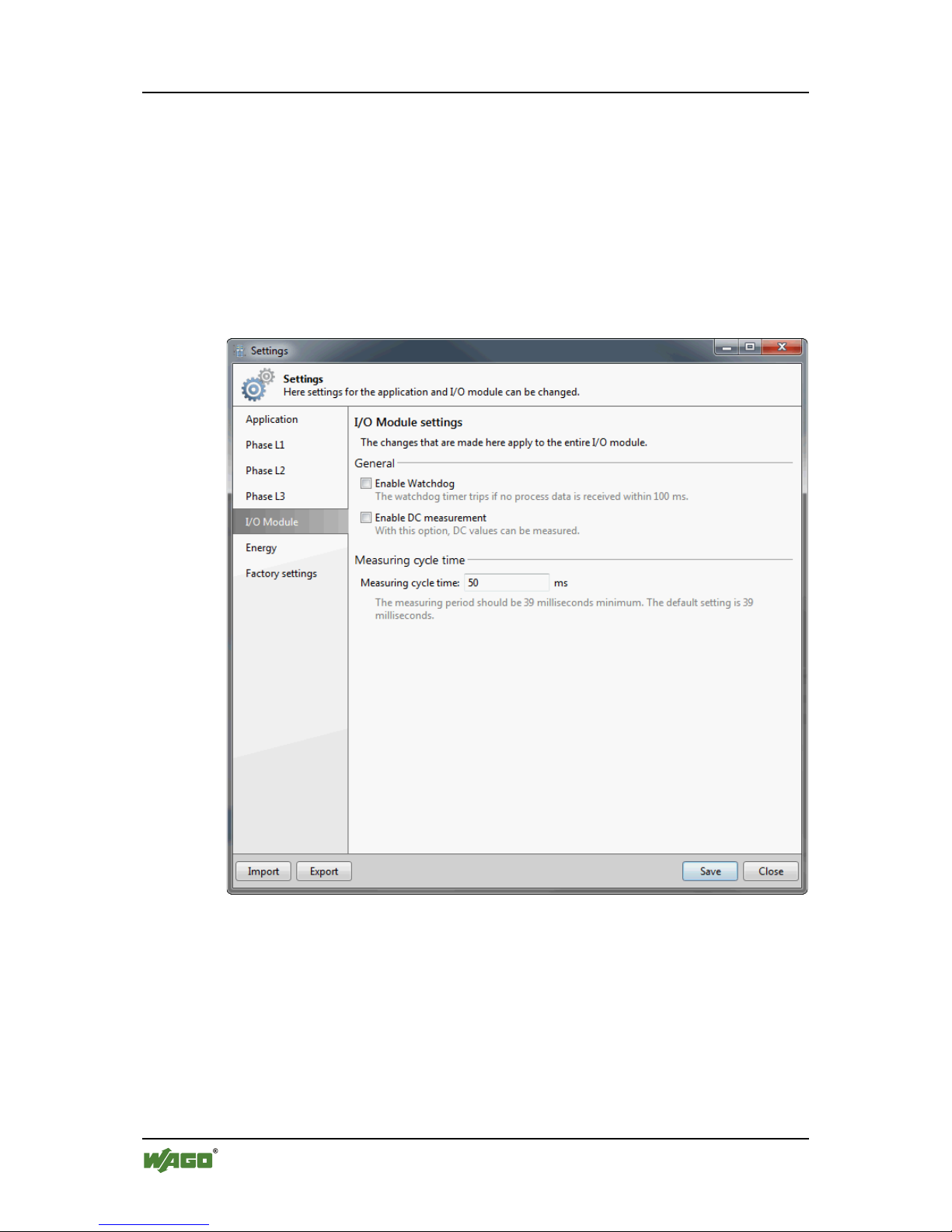
64 Commissioning WAGO-I/O-SYSTEM 750
750-493 3-Phase Power Measurement Module
Manual
Version 1.2.0
8.1.3 "I/O Module" Tab
On the "I/O Module" tab you can do two general settings for the entire I/O
module. These are "Enable watchdog" and "Enable DC measurement". The
watchdog deactivates the green status LED "A" if no process data is received
within 100 ms.
You can also specify the measuring cycle time. The minimum value is 39 ms,
default is also 39 ms. The maximum value is 24375 ms.
Figure 20: "I/O Module" Tab
Page 65

WAGO-I/O-SYSTEM 750 Commissioning 65
750-493 3-Phase Power Measurement Module
Manual
Version 1.2.0
8.1.4 "Energy" Tab
After entering a password, you can set or reset the energy values per phase on the
"Energy" tab. The initial password is: wago. Please change this password on first
use by clicking [Change password].
The energy values are saved automatically every 15 minutes. Use the [Save] and
[Delete] commands to save the actual value or set it to 0. These actions are carried
out immediately and cannot be undone. Therefore, the [Save] button is disabled
at the bottom of the window.
Figure 21: "Energy" Tab
Page 66

66 Commissioning WAGO-I/O-SYSTEM 750
750-493 3-Phase Power Measurement Module
Manual
Version 1.2.0
8.1.5 "Factory Settings" Tab
After entering a password (see "Energy" tab above), you can reset all parameters
of the I/O module to their factory settings on the "Factory Settings" tab.
Use I/O Module Settings [Restore] to reset the I/O module settings only.
Calibration data remains unchanged.
Use Calibration Data [Restore] to reset the calibration data only. The I/O module
settings remain unchanged.
Use Total [Restore] to reset all I/O module settings and calibration data.
These actions are carried out immediately and cannot be undone. Therefore, the
[Save] button is disabled at the bottom of the window.
Figure 22: "Factory Settings" Tab
Pos: 89 /Dokum entati on allg emein/ Glie derung sele mente /---Seite nwe chsel --- @ 3\mod_1221108045078_0.docx @ 21810 @ @ 1
Page 67

WAGO-I/O-SYSTEM 750 Commissioning 67
750-493 3-Phase Power Measurement Module
Manual
Version 1.2.0
Pos: 90 /Seri e 7 50 ( WA GO-I/ O-SYST EM )/I n B etri eb neh men/ Par amet rier en üb er Reg ist er kom muni ka tion/ Reg ist erbel eg ung 75 0-493 @ 13\mod_1349346399958_21.docx @ 103953 @ 3 @ 1
8.1.6 Register Assignment
The following tables display the assignments and factory settings for the
individual registers written by setting the parameters.
The factory settings are the same for all three channels.
Table 25: Register 0
Register 0 - Overflow register for energy consumption
Function
Data type
Access
Factory setting
Overflow register for energy consumption
UINT
R/W
----
This overflow register is incremented when the register for energy consumption (can be read
out via process data index 4) starts to overrun. The overflow register can only be read out via
register communication.
When the energy consumption data is deleted, this register is likewise deleted.
Table 26: Register 7
Register 7 - Command register
Function
Data type
Access
Factory setting
Command register
UINT
R/W
0x0000
0x0000
No function.
If needed, enter the value 0x0000 into the command register to delete it.
0x1004
Deleting energy consumption data (user password must be set).
Write the value 0x1004 to the command register to delete the energy
consumption value stored in the process data (process data index 4) and the
overflow register for energy consumption (R0).
0x1005
Deleting the maximum current value.
Write the value 0x1005 to the command register to delete the maximum current
value stored in the process data (process data index 5).
0x1006
Deleting the maximum voltage value.
Write the value 0x1006 to the command register to delete the maximum voltage
value stored in the process data (process data index 6).
0x1009
Deleting the minimum current value.
Write the value 0x1009 to the command register to delete the minimum current
value stored in the process data (process data index 9).
0x100A
Deleting the minimum voltage value.
Write the value 0x100A to the command register to delete the minimum voltage
value stored in the process data (process data index 10).
0x1014
Intermediate saving of energy consumption value (user password must be set).
The I/O module registers the energy consumption in the RAM and only saves
these values to the EEPROM in 15 minute cycles.
If you wish to deactivate the I/O module without losing the energy consumption
value measured since the last storage cycle, you can store the actual value
manually to the EEPROM using this command.
Lifetime of EEPROM!
If the energy values are stored in 60 s cycles, the lifetime of the EEPROM amounts to 19
years. Storing every 30 s the lifetime decreases to 9.5 years!
0x1020
Deleting all minimum and maximum values.
Write the value 0x1020 to the command register to delete all minimum and
maximum values.
0x7000
Restoring factory settings (user password must be set).
Write the value 0x7000 to the command register to restore the factory settings of
registers 32 and 35 … 39. Resetting one channel automatically resets the two
other channels.
Page 68

68 Commissioning WAGO-I/O-SYSTEM 750
750-493 3-Phase Power Measurement Module
Manual
Version 1.2.0
Table 27: Register 32
Register 32 - Mode setting
Function
Data type
Access
Factory setting
Mode setting
Flags
R/W
0x0020
Bit 0: enUserScaling
0: *
User scaling deactivated; the transformation ratio is 1:1.
1:
User scaling activated; the transformation ratio is 1: (divisor for the current
transformer ratio).
Bit 1: reserved
Bit 2: disWdTimer
0: *
Watchdog timer activated: The watchdog trips and deactivates the green status LED
“A” if no process data is received within 100 ms.
1:
Watchdog timer not activated.
Bit 3: enFlexProcImage
0: *
Simple process image (compatibility mode)
1:
Flexible process image
Bit 4: skipDCFilter
0: *
DC filter activated
1:
DC filter is bypassed
Bit 5: reserved
Bit 6: invEnergySign
0: *
Energy consumption measurement not inverted.
1:
Energy consumption measurement inverted (generating operation)
Bit 7: enClrMinMaxValues
0: *
Automatic deleting of minimum and maximum current, voltage and power values
deactivated.
1:
Automatic deleting of minimum and maximum current, voltage and power values
activated.
Bit 8 … 15: reserved
* Factory setting
Table 28: Register 35
Register 35 - Scaling factor for measuring energy
Function
Data type
Access
Factory setting
Scaling factor for measuring energy
UINT
R/W
0x0004
750-493
750-493/000-001
0:
1 mWh
5 mWh
1:
0.01 Wh
0.05 Wh
2:
0.1 Wh
0.5 Wh
3:
1 Wh
5 Wh
4: *
0.01 kWh
0.05 kWh
5:
0.1 kWh
0.5 kWh
6:
1 kWh
5 kWh
≥7:
reserved
reserved
* Factory setting
Table 29: Register 36
Register 36 - Undervoltage threshold
Function
Data type
Access
Factory setting
Undervoltage threshold;
resolution 0.1 V
UINT R/W 0x0064 (10 V)
Page 69

WAGO-I/O-SYSTEM 750 Commissioning 69
750-493 3-Phase Power Measurement Module
Manual
Version 1.2.0
Table 30: Register 37
Register 37 - Divisor for current transformer ratio D-CTR
Function
Data type
Access
Factory setting
Divisor for current transformer ratio;
must be activated via register 32, bit 0
UINT R/W
0x0001
(D-CTR = 1)
Table 31: Register 38
Register 38 - Time constant for automatic deleting of minimum and
maximum values
Function
Data type
Access
Factory setting
Time constant for automatic deleting of
minimum and maximum values;
resolution 10 ms;
must be activated via register 32, bit 7
UINT R/W 0x00C8 (2000 ms)
Table 32: Register 39
Register 39 - Measuring cycle period
Function
Data type
Access
Factory setting
Measuring cycle period;
resolution 1 ms
UINT R/W 0x0027 (39 ms)
Pos: 91 /Dokum entati on allg emei n/Gl ie derung sel em ente /---Seit enwe chs el--- @ 3\mod_1221108045078_0.docx @ 21810 @ @ 1
Page 70

70 Commissioning WAGO-I/O-SYSTEM 750
750-493 3-Phase Power Measurement Module
Manual
Version 1.2.0
Pos: 92 /All e Ser i en (A llg emei ne M od ule) /Üb ers chri fte n für al le S eri en/ __ n oc h nic ht ei ns orti ert e Üb ers chri fte n m üss en n och eins orti er t w erden __/ An zeig en der Mes swert e mit WA GO-I/O-CH ECK - Ü b ersc hrif t 2 @ 1 3\mod_1355494395030_21.docx @ 107680 @ 2 @ 1
8.2 Displaying the Measured Values via WAGO-I/OCHECK
Pos: 93 /Seri e 7 50 ( WA GO-I/ O-SYST EM )/I n B etri eb neh men/ Anzei g en d er Me ss wer te mi t WAGO- I/O-CH ECK 75 0-049 3 @ 16\mo d_1372771300798_21.docx @ 125355 @ @ 1
The measured values are displayed in the "3-phase power measurement" dialog in
several views.
The Overview view displays the measured values of all three phases
continuously. These are:
• Current, voltage Lx-N, active power, cos phi and frequency.
An undervoltage is identified as a red square.
Change of the Measuring Units!
Specify the prefixes of the measuring units by selecting Home > Settings >
Application. See section "Configuration with WAGO-I/O-CHECK" >
"Application" Tab.
The units can only be changed in the lists with the same physical variables. For
lists with different variables, base units are always used!
Figure 23: Measured Values, Overview
Page 71

WAGO-I/O-SYSTEM 750 Commissioning 71
750-493 3-Phase Power Measurement Module
Manual
Version 1.2.0
Selecting Phase L1 (resp. L2 or L3) Measurements, the measured values of the
respective phase are displayed in detailed including min. and max. values and
active energy.
Figure 24: Measured Values, Phases
Page 72

72 Commissioning WAGO-I/O-SYSTEM 750
750-493 3-Phase Power Measurement Module
Manual
Version 1.2.0
Currents/Voltages displays all three currents with min. and max. values, all three
voltages with min. and max. values, undervoltages and all three frequencies.
Figure 25: Measured Values, Currents and Voltages
Page 73

WAGO-I/O-SYSTEM 750 Commissioning 73
750-493 3-Phase Power Measurement Module
Manual
Version 1.2.0
If you select Power, the active power of the three phases is displayed with min.
and max. values and the power factor cos phi.
Figure 26: Measured Values, Power
Page 74

74 Commissioning WAGO-I/O-SYSTEM 750
750-493 3-Phase Power Measurement Module
Manual
Version 1.2.0
If you select Energies, the three total active energies are displayed that have been
consumed/generated since the beginning of the measurement.
Figure 27: Measured Values, Energies
Page 75

WAGO-I/O-SYSTEM 750 Commissioning 75
750-493 3-Phase Power Measurement Module
Manual
Version 1.2.0
Selecting DC Measurements, you can see the measured DC components of the
three measuring signals, i.e. current, voltage and power of each measuring signal
is displayed. Select DC mode on the "I/O Module" tab. The AC variables are then
not measured and displayed.
Figure 28: Measured Values, DC
Page 76

76 Commissioning WAGO-I/O-SYSTEM 750
750-493 3-Phase Power Measurement Module
Manual
Version 1.2.0
On the Measurement Recording view, 3 measured variables are represented in
chronological sequence. You can select the measured variables you want to see in
the 3 drop-down lists.
Figure 29: Measured Values, Recording
In general, you can select in the 3 waveforms whether:
• The samples are displayed over a certain period of time (with ).
or
• A certain number of samples is displayed (with ).
You can then enter the duration by start and end time or the number of samples. In
both cases, the measurement interval, i.e. sample rate, can also be selected from
250 to 300,000 ms.
Clicking the arrow, the [Start] button generates a drop-down list in which you can
select "No Export". By doing this, no export CSV file is generated.
If you click [Start] as usual, a "Save" window opens in which you can specify the
storage location for the CSV file. After you have specified the storage location the
measurement starts. Use [Stop] to stop the measurement prematurely. For
examples of CSV files, see section "Appendix".
Use the mouse wheel to zoom in and out within the three graphic waveforms.
Hold down the left mouse button to move the displayed range.
Click again to follow the current waveform.
Pos: 94 /Dokum entati on allg emein/ Glie derung sele mente /---Seite nwe chsel --- @ 3\mod_1221108045078_0.docx @ 21810 @ @ 1
Page 77

WAGO-I/O-SYSTEM 750 Diagnostics 77
750-493 3-Phase Power Measurement Module
Manual
Version 1.2.0
Pos: 95 /All e Ser i en (A llg emei ne M od ule) /Üb ers chri fte n für al le S eri en/D iag nos e/Di ag nos e - Ü bersc hri ft 1 @ 4\mod_1240831069471_21.docx @ 31372 @ 1 @ 1
9 Diagnostics
Pos: 96 /Seri e 7 50 ( WA GO-I/ O-SYSTEM)/Diagnose/Busklemmen/Diagnose 750-0493 @ 15\mod_1366806737193_21.docx @ 117960 @ @ 1
8 LEDs A … H indicate the operation status and possible errors.
The meaning of the indications is as follows:
Table 33: LED Diagnosis
LED
Status
Message
A
Off
No operational readiness or
the internal data bus communication is interrupted.
Green
Operational readiness and correct internal data bus
communication
B
Off
No error
Red
Undervoltage L1 – N *
C
Off
No error
Red
Override of a current measuring path
D
Off
No error
Red
High measuring error, caused by undervoltage
of a voltage measuring path
E
Off
No error
Red
Undervoltage L2 – N *
F
Off
No error
Red
Undervoltage L3 – N *
G
Off
No error
Red
Override of a voltage measuring path
H
Off
No error
Yellow
Error of the phase sequence L1-L2-L3
*The undervoltage threshold is set on the tabs „Phase L1“, „Phase L2“ and „Phase L3“.
Pos: 97 /Dokum entati on allg emein/ Glie derung sele mente /---Seite nwe chsel --- @ 3\mod_1221108045078_0.docx @ 21810 @ @ 1
Page 78

78 Appendix WAGO-I/O-SYSTEM 750
750-493 3-Phase Power Measurement Module
Manual
Version 1.2.0
Pos: 98 /All e Ser i en (A llg emei ne M od ule) /Üb ers chri fte n für al le S eri en/A nha ng - Zub ehör/ Anh ang - Üb erschr ift 1 @ 4\mod_1239874070437_21.docx @ 30560 @ 1 @ 1
10 Appendix
Pos: 99 /Seri e 7 50 ( WA GO-I/ O-SYST EM )/ Anh ang/ Beis piel e für C SV-D ateie n 750- 493 @ 14 \mod_1363161491209_21.docx @ 114320 @ 22 @ 1
10.1 CSV Data File “Snapshot”
The following table is an example CSV data file generated in WAGO-I/OCHECK with the function [Snapshot].
All actual measured values and set parameters are listed.
7/30/2013 11:50:46 AM
WAGO
Kontakttechnik
GmbH & Co. KG
I/O-Check-
3 Phase
Power
Measurement
(1.3.3.366)
0750-0493
/0000-0000
Measurements
Current (eff.) L1 0.261 A
Current (eff.) L3 0.188 A
Current (eff.) L2 0.48 A
Voltage (eff.) L1-N 230.4 V
Voltage (eff.) L2-N 230.4 V
Voltage (eff.) L3-N 230.4 V
Active Power L1 38.1 W
Active Power L2 18 W
Active Power L3 -25.8 W
cos phi L1 0.75
cos phi L2 0.11
cos phi L3 -0.84
Frequency L1 50 Hz
Frequency L2 50 Hz
Frequency L3 49.9 Hz
Minimum Current (eff.) L1 0.162 A
Minimum Current (eff.) L2 0.107 A
Minimum Current (eff.) L3 0.378 A
Maximum Current (eff.) L1 3.049 A
Maximum Current (eff.) L2 4.727 A
Maximum Current (eff.) L3 25.615 A
Minimum Voltage (eff.) L1-N 0 V
Minimum Voltage (eff.) L2-N 0 V
Minimum Voltage (eff.) L3-N 0 V
Maximum Voltage (eff.) L1-N 230.6 V
Page 79

WAGO-I/O-SYSTEM 750 Appendix 79
750-493 3-Phase Power Measurement Module
Manual
Version 1.2.0
Maximum Voltage (eff.) L2-N 230.6 V
Maximum Voltage (eff.) L3-N 230.6 V
Minimum Active Power L1 -0.1 W
Minimum Active Power L2 -0.2 W
Minimum Active Power L3 -28.2 W
Maximum Active Power L1 42.8 W
Maximum Active Power L2 30.2 W
Maximum Active Power L3 3276.7 W
Active Energy L1 60 Wh
Active Energy L2 17.812 Wh
Active Energy L3 0 Wh
Parameter Phase L1
Transformer ratio 300
Heed transformer ratio True
Flexible process image active False
Leading sign cos phi positive and
negative True
Energy measurement generator
operation False
Automatic reset of the min./max.
values False
Scaling factor energy values 1 Wh
Undervoltage threshold 0 V
Interval - reset: min./max. values 2000 ms
Parameter Phase L2
Transformer ratio 700
Heed transformer ratio True
Flexible process image active False
Leading sign cos phi positive and
negative True
Energy measurement generator
operation False
Automatic reset of the min./max.
values False
Scaling factor energy values 1 mWh
Undervoltage threshold 0 V
Interval - reset: min./max. values 2000 ms
Parameter Phase L3
Page 80

80 Appendix WAGO-I/O-SYSTEM 750
750-493 3-Phase Power Measurement Module
Manual
Version 1.2.0
Transformer ratio 200
Heed transformer ratio True
Flexible process image active False
Leading sign cos phi positive and
negative True
Energy measurement generator
operation False
Automatic reset of the min./max.
values False
Scaling factor energy values 1 mWh
Undervoltage threshold 0 V
Interval - reset: min./max. values 2000 ms
I/O Module Parameters
DC current measurement active False
Watchdog process data
communication active False
Measuring cycle time 50 ms
10.2 CSV Data File “Measurement Recording”
The following table shows an example CSV data file generated in the view
“Measurement Recording” with [Start]. In this example the variable “Voltage
(eff.) L1-N” was selected shown as measuring series with 10 values.
04.07.2013 07:47:24
WAGO
Kontakttechnik
GmbH & Co.
KG
I/O-Check-
3 Phase
Power
Measurement
(1.3.3.366)
0750-0493
/0000-0000
Voltage
(eff.) L1-N
V
04.07.2013 07:47:24 230
04.07.2013 07:47:25 230
04.07.2013 07:47:25 229.9
04.07.2013 07:47:26 230
04.07.2013 07:47:26 229.9
04.07.2013 07:47:27 230
04.07.2013 07:47:27 229.9
04.07.2013 07:47:28 230
04.07.2013 07:47:28 230
04.07.2013 07:47:29 230
Page 81

WAGO-I/O-SYSTEM 750 Use in Hazardous Environments 81
750-493 3-Phase Power Measurement Module
Manual
Version 1.2.0
Pos: 100.1 / Alle Ser ie n (All ge mei ne M odul e) /Ei nsatz i n E x-Berei chen /Ei nsatz in e xplosi onsg efähr deten Ber eic hen - Über sc hrift 1 @ 3\ mod_1224075191281_21.docx @ 24084 @ 1 @ 1
11 Use in Hazardous Environments
Pos: 100.2 / Ser ie 7 50 ( WAG O-I/ O-SYST EM) /Ei nsatz i n Ex-Ber eiche n/Ein satzb ereic h Seri e 750 @ 3\m od_ 1234272230203_21.docx @ 27500 @ @ 1
The WAGO-I/O-SYSTEM 750 (electrical equipment) is designed for use in
Zone 2 hazardous areas.
The following sections include both the general identification of components
(devices) and the installation regulations to be observed. The individual
subsections of the “Installation Regulations” section must be taken into account if
the I/O module has the required approval or is subject to the range of application
of the ATEX directive.
Pos: 100.3 /D ok um entati o n allg em ei n/Gli eder ung sel ement e/---S eiten wec hs el--- @ 3\mod_1221108045078_0.docx @ 21810 @ @ 1
Page 82

82 Use in Hazardous Environments WAGO-I/O-SYSTEM 750
750-493 3-Phase Power Measurement Module
Manual
Version 1.2.0
Pos: 100.4 / Ser ie 7 50 ( WAG O-I/ O-SYST EM) /Ei nsatz i n Ex-Ber eiche n/B eispiel hafter Aufb au der K ennzei chnung - Über schri ft 2 @ 3\mod_1224157499140_21.docx @ 24182 @ 2 @ 1
11.1 Marking Configuration Examples
Pos: 100.5 / Ser ie 7 50 ( WAG O-I/ O-SYST EM) /Ei nsatz i n Ex-Ber eic hen/ K ennz eich nung für Eur o pa g emäß AT EX u nd I EC- EX - Ü bers chri ft 3 @ 3\mod_1224157620203_21.docx @ 24185 @ 3 @ 1
11.1.1 Marking for Europe According to ATEX and IEC-Ex
Pos: 100.6 /S erie 750 ( W AGO -I/O-SY ST EM)/Ei ns atz i n E x-Berei che n/ Beis pi elbe druc ku ng d er A TE X- und IEC-Ex-zugelass en en B uskl em men g e mäß C EN ELEC u nd IEC _ 201 3 @ 1 4\mod_1360569228625_21.docx @ 111294 @ @ 1
Figure 30: Side Marking Example for Approved I/O Modules According to ATEX and IECEx
Figure 31: Text Detail – Marking Example for Approved I/O Modules According to ATEX and
IECEx.
Page 83

WAGO-I/O-SYSTEM 750 Use in Hazardous Environments 83
750-493 3-Phase Power Measurement Module
Manual
Version 1.2.0
Table 34: Description of Marking Example for Approved I/O Modules According to ATEX and
IECEx
Printing on Text
Description
TÜV 07 ATEX 554086 X
IECEx TUN 09.0001 X
Approving authority and certificate numbers
Dust
II
Equipment group: All except mining
3D
Category 3 (Zone 22)
Ex
Explosion protection mark
tc Dc
Type of protection and equipment protection
level (EPL):protection by enclosure
IIIC
Explosion group of dust
T 135°C
Max. surface temperature of the enclosure
(without a dust layer)
Mining
I
Equipment group: Mining
M2
Category: High level of protection
Ex
Explosion protection mark
d Mb
Type of protection and equipment protection
level (EPL): Flameproof enclosure
I
Explosion group for electrical equipment for
mines susceptible to firedamp
Gases
II
Equipment group: All except mining
3G
Category 3 (Zone 2)
Ex
Explosion protection mark
nA Gc
Type of protection and equipment protection
level (EPL): Non-sparking equipment
nC Gc
Type of protection and equipment protection
level (EPL): Sparking apparatus with protected
contacts. A device which is so constructed that
the external atmosphere cannot gain access to the
interior
IIC
Explosion group of gas and vapours
T4
Temperature class: Max. surface temperature
135°C
Pos: 100.7 /D ok um entati o n allg em ei n/Gli eder ung sel eme nte/ ---Seit enw echs el--- @ 3 \mod_1221108045078_0.docx @ 21810 @ @ 1
Page 84

84 Use in Hazardous Environments WAGO-I/O-SYSTEM 750
750-493 3-Phase Power Measurement Module
Manual
Version 1.2.0
Pos: 100.8 / Ser ie 7 50 ( WAG O-I/ O-SYST EM) /Ei nsatz i n Ex-Ber eic hen/ B eispi elb edr uck ung der Ex-i- und IEC-Ex-i-zugelass enen Bus kle mmen ge mäß CEN ELEC u nd IEC_ 2013 @ 14\ mod_1360569320118_21.docx @ 111298 @ @ 1
Figure 32: Side Marking Example for Approved Ex i I/O Modules According to ATEX and
IECEx.
Figure 33: Text Detail – Marking Example for Approved Ex i I/O Modules According to ATEX
and IECEx.
Page 85

WAGO-I/O-SYSTEM 750 Use in Hazardous Environments 85
750-493 3-Phase Power Measurement Module
Manual
Version 1.2.0
Table 35: Description of Marking Example for Approved Ex i I/O Modules According to ATEX and
IECEx
Inscription Text
Description
TÜV 07 ATEX 554086 X
IECEx TUN 09.0001X
TÜV 12 ATEX 106032 X
IECEx TUN 12.0039 X
Approving authority and certificate numbers
Dust
II
Equipment group: All except mining
3(1)D
Category 3 (Zone 22) equipment containing a safety
device for a category 1 (Zone 20) equipment
3(2)D
Category 3 (Zone 22) equipment containing a safety
device for a category 2 (Zone 21) equipment
Ex
Explosion protection mark
tc Dc
Type of protection and equipment protection level
(EPL): protection by enclosure
[ia Da]
Type of protection and equipment protection level
(EPL): associated apparatus with intrinsic safety
circuits for use in Zone 20
[ib Db]
Type of protection and equipment protection level
(EPL): associated apparatus with intrinsic safety
circuits for use in Zone 21
IIIC
Explosion group of dust
T 135°C
Max. surface temperature of the enclosure (without a
dust layer)
Mining
I
Equipment Group: Mining
M2 (M1)
Category: High level of protection with electrical
circuits which present a very high level of protection
Ex d Mb
Explosion protection mark with Type of protection
and equipment protection level (EPL): Flameproof
enclosure
[ia Ma]
Type of protection and equipment protection level
(EPL): associated apparatus with intrinsic safety
electrical circuits
I Explosion group for electrical equipment for mines
susceptible to firedamp
Page 86

86 Use in Hazardous Environments WAGO-I/O-SYSTEM 750
750-493 3-Phase Power Measurement Module
Manual
Version 1.2.0
Table 35: Description of Marking Example for Approved Ex i I/O Modules According to ATEX and
IECEx
Gases
II
Equipment group: All except mining
3(1)G
Category 3 (Zone 2) equipment containing a safety
device for a category 1 (Zone 0) equipment
3(2)G
Category 3 (Zone 2) equipment containing a safety
device for a category 2 (Zone 1) equipment
Ex
Explosion protection mark
nA Gc
Type of protection and equipment protection level
(EPL): Non-sparking equipment
[ia Ga]
Type of protection and equipment protection level
(EPL): associated apparatus with intrinsic safety
circuits for use in Zone 0
[ia Gb]
Type of protection and equipment protection level
(EPL): associated apparatus with intrinsic safety
circuits for use in Zone 1
IIC
Explosion group of gas and vapours
T4
Temperature class: Max. surface temperature 135°C
Pos: 100.9 /D ok um entati o n allg em ei n/Gli eder ung sel eme nte/ ---Seit enw echs el--- @ 3 \mod_1221108045078_0.docx @ 21810 @ @ 1
Page 87

WAGO-I/O-SYSTEM 750 Use in Hazardous Environments 87
750-493 3-Phase Power Measurement Module
Manual
Version 1.2.0
Pos: 100.10 /Ser ie 750 ( WA GO-I /O-SY STEM) /Ei nsat z in Ex-Ber ei che n/K en nzeic hnu ng f ür A mer i ka ge mäß N EC 50 0 - Ü bers chri ft 3 @ 3 \mod_1224158423187_21.docx @ 24188 @ 3 @ 1
11.1.2 Marking for America According to NEC 500
Pos: 100.11 /Ser ie 750 ( WA GO-I /O-SY STEM) /Ei nsat z in Ex-Ber ei che n/Bei spi elb edr uc kung g em äß N EC 500 _20 13 @ 14\ mod_1360580302684_21.docx @ 111353 @ @ 1
Figure 34: Side Marking Example for I/O Modules According to NEC 500
Figure 35: Text Detail – Marking Example for Approved I/O Modules According to NEC 500
Table 36: Description of Marking Example for Approved I/O Modules According to NEC 500
Printing on Text
Description
CL I
Explosion protection group (condition of use
category)
DIV 2
Area of application
Grp. ABCD
Explosion group (gas group)
Op temp code T4
Temperature class
Pos: 100.12 /Do kume ntati on allge mein/ Glied erung selem ente/ ---Seite nwech sel--- @ 3\ mod_1221108045078_0.docx @ 21810 @ @ 1
Page 88

88 Use in Hazardous Environments WAGO-I/O-SYSTEM 750
750-493 3-Phase Power Measurement Module
Manual
Version 1.2.0
Pos: 100.13 /Al le S eri en ( Allg em ein e Mod ule) /Ei nsa tz i n E x-B ereic hen/ Err icht ung sbest im munge n - Ü bersc hrift 2 @ 3\mod_1232453624234_21.docx @ 26370 @ 2 @ 1
11.2 Installation Regulations
Pos: 100.14 /Al le S eri en ( Allg em ein e Mod ule) /Ei nsa tz i n E x-B ereiche n/Er richt ungsb esti mmunge n Einl eitung _2013 @ 14\mod_1360582328318_21.docx @ 111371 @ @ 1
For the installation and operation of electrical equipment in hazardous areas, the
valid national and international rules and regulations which are applicable at the
installation location must be carefully followed.
Pos: 100.15 /Do kume ntati on allge mein/ Gli ed erung sel eme nte/---S eite nwec hsel --- @ 3\mod_1221108045078_0.docx @ 21810 @ @ 1
Page 89

WAGO-I/O-SYSTEM 750 Use in Hazardous Environments 89
750-493 3-Phase Power Measurement Module
Manual
Version 1.2.0
Pos: 100.16 /Ser ie 750 ( WA GO-I /O-SY STEM) /Ei nsat z in Ex-Ber eich en/B esond ere Be dingu ngen für den sich eren E x-Betri eb g e m. ATE X-Zertifikat TÜV 07 ATEX 554086_X_2013_2 @ 15\mod_1368620071975_21.docx @ 119778 @ 3 @ 1
11.2.1 Special Conditions for Safe Use (ATEX Certificate TÜV 07
ATEX 554086 X)
1. For use as Gc- or Dc-apparatus (in zone 2 or 22) the Field bus Independent
I/O Modules WAGO-I/O-SYSTEM 750-*** shall be erected in an
enclosure that fulfils the requirements of the applicable standards (see the
marking) EN 60079-0, EN 60079-11, EN 60079-15 and EN 60079-31.
For use as group I electrical apparatus M2 the apparatus shall be erected in
an enclosure that ensures a sufficient protection according to EN 60079-0
and EN 60079-1 and the degree of protection IP64.
The compliance of these requirements and the correct installation into an
enclosure or a control cabinet of the devices shall be certified by an ExNB.
2. Measures have to be taken outside of the device that the rating voltage is not
being exceeded of more than 40 % because of transient disturbances.
3. Dip-switches, binary-switches and potentiometers, connected to the module
may only be actuated when explosive atmosphere can be excluded.
4. The connecting and disconnecting of the non-intrinsically safe circuits is
only permitted during installation, for maintenance or for repair purposes.
The temporal coincidence of explosion hazardous atmosphere and
installation, maintenance resp. repair purposes shall be excluded.
This is although and in particular valid for the interfaces “Memory-Card”,
“USB”, “Fieldbus connection”, “Configuration and programming interface”,
“antenna socket”, “D-Sub”, “DVI-port” and the “Ethernet interface”. These
interfaces are not energy limited or intrinsically safe circuits. An operating
of those circuits is in the behalf of the operator.
5. For the types 750-606, 750-625/000-001, 750-487/003-000, 750-484 and
750-633 the following shall be considered: The Interface circuits shall be
limited to overvoltage category I/II/III (non mains/mains circuits) as defined
in EN 60664-1.
6. For replaceable fuses the following shall be considered: Do not remove or
replace the fuse when the apparatus is energized.
7. The following warnings shall be placed nearby the unit:
WARNING – DO NOT REMOVE OR REPLACE FUSE WHEN
ENERGIZED
WARNING – DO NOT SEPARATE WHEN ENERGIZED
WARNING – SEPARATE ONLY IN A NON-HAZARDOUS AREA
Pos: 100.17 /Do kume ntati on allge mein/ Glied erung selem ente/ ---Seite nwech sel--- @ 3\ mod_1221108045078_0.docx @ 21810 @ @ 1
Page 90

90 Use in Hazardous Environments WAGO-I/O-SYSTEM 750
750-493 3-Phase Power Measurement Module
Manual
Version 1.2.0
Pos: 100.18 /Ser ie 750 ( WA GO-I /O-SY STEM) /Ei nsat z in Ex-Ber ei che n/Bes ondere Beding unge n für den s icher en Ex-B etrie b g em. ATE X-Zertifikat TÜV 12 ATEX 106032x_2013_2 @ 15\mod_1368620479454_21.docx @ 119782 @ 3 @ 1
11.2.2 Special Conditions for Safe Use (ATEX Certificate TÜV 12
ATEX 106032 X)
1. For use as Gc- or Dc-apparatus (in zone 2 or 22) the Field bus Independent
I/O Modules WAGO-I/O-SYSTEM 750-*** Ex i shall be erected in an
enclosure that fulfils the requirements of the applicable standards (see the
marking) EN 60079-0, EN 60079-11, EN 60079-15 and EN 60079-31.
For use as group I electrical apparatus M2 the apparatus shall be erected in
an enclosure that ensures a sufficient protection according to EN 60079-0
and EN 60079-1 and the degree of protection IP64.
The compliance of these requirements and the correct installation into an
enclosure or a control cabinet of the devices shall be certified by an ExNB.
2. Measures have to be taken outside of the device that the rating voltage is not
being exceeded of more than 40 % because of transient disturbances.
3. The connecting and disconnecting of the non-intrinsically safe circuits is
only permitted during installation, for maintenance or for repair purposes.
The temporal coincidence of explosion hazardous atmosphere and
installation, maintenance resp. repair purposes shall be excluded.
4. For the type the following shall be considered: The Interface circuits shall
be limited to overvoltage category I/II/III (non mains/mains circuits) as
defined in EN 60664-1.
Pos: 100.19 /Do kume ntati on allge mein/ Glied erung selem ente/ ---Seite nwech sel--- @ 3\ mod_1221108045078_0.docx @ 21810 @ @ 1
Page 91

WAGO-I/O-SYSTEM 750 Use in Hazardous Environments 91
750-493 3-Phase Power Measurement Module
Manual
Version 1.2.0
Pos: 100.20 /Ser ie 750 ( WA GO-I /O-SY STEM) /Ei nsat z in Ex-Ber eich en/B esond ere Be dingu ngen für den sich eren E x-Betrieb g e m. IEC- Ex-Zertifikat TUN 09.0001 X_2013_2 @ 15\mod_1368620660911_21.docx @ 119786 @ 3 @ 1
11.2.3 Special Conditions for Safe Use (IEC-Ex Certificate TUN
09.0001 X)
1. For use as Gc- or Dc-apparatus (in zone 2 or 22) the Field bus Independent
I/O Modules WAGO-I/O-SYSTEM 750-*** shall be erected in an
enclosure that fulfils the requirements of the applicable standards (see the
marking) IEC 60079-0, IEC 60079-11, IEC 60079-15 and IEC 60079-31.
For use as group I electrical apparatus M2 the apparatus shall be erected in
an enclosure that ensures a sufficient protection according to IEC 60079-0
and IEC 60079-1 and the degree of protection IP64.
The compliance of these requirements and the correct installation into an
enclosure or a control cabinet of the devices shall be certified by an ExCB.
2. Measures have to be taken outside of the device that the rating voltage is not
being exceeded of more than 40 % because of transient disturbances.
3. DIP-switches, binary-switches and potentiometers, connected to the module
may only be actuated when explosive atmosphere can be excluded.
4. The connecting and disconnecting of the non-intrinsically safe circuits is
only permitted during installation, for maintenance or for repair purposes.
The temporal coincidence of explosion hazardous atmosphere and
installation, maintenance resp. repair purposes shall be excluded.
This is although and in particular valid for the interfaces “Memory-Card”,
“USB”, “Fieldbus connection”, “Configuration and programming interface”,
“antenna socket”, “D-Sub”, “DVI-port” and the “Ethernet interface”. These
interfaces are not energy limited or intrinsically safe circuits. An operating
of those circuits is in the behalf of the operator.
5. For the types 750-606, 750-625/000-001, 750-487/003-000, 750-484 and
750-633 the following shall be considered: The Interface circuits shall be
limited to overvoltage category I/II/III (non mains/mains circuits) as defined
in IEC 60664-1.
6. For replaceable fuses the following shall be considered: Do not remove or
replace the fuse when the apparatus is energized.
7. The following warnings shall be placed nearby the unit:
WARNING – DO NOT REMOVE OR REPLACE FUSE WHEN
ENERGIZED
WARNING – DO NOT SEPARATE WHEN ENERGIZED
WARNING – SEPARATE ONLY IN A NON-HAZARDOUS AREA
Pos: 100.21 /Do kume ntati on allge mein/ Glied erung selem ente/ ---Seite nwech sel--- @ 3\ mod_1221108045078_0.docx @ 21810 @ @ 1
Page 92

92 Use in Hazardous Environments WAGO-I/O-SYSTEM 750
750-493 3-Phase Power Measurement Module
Manual
Version 1.2.0
Pos: 100.22 /Ser ie 750 ( WA GO-I /O-SY STEM) /Ein satz in E x-Ber eich en/Bes ond ere Be dingung en für de n sich eren E x-Betrieb g em. IEC- Ex-Zertifikat TUN 12.0039 X_2013_2 @ 15\mod_1368620821493_21.docx @ 119790 @ 3 @ 1
11.2.4 Special Conditions for Safe Use (IEC-Ex Certificate IECEx
TUN 12.0039 X)
1. For use as Gc- or Dc-apparatus (in zone 2 or 22) the Field bus independent
I/O Modules WAGO-I/O-SYSTEM 750-*** Ex i shall be erected in an
enclosure that fulfils the requirements of the applicable standards (see the
marking) IEC 60079-0, IEC 60079-11, IEC 60079-15, IEC 60079-31.
For use as group I electrical apparatus M2 the apparatus shall be erected in
an enclosure that ensures a sufficient protection according to IEC 60079-0
and IEC 60079-1 and the degree of protection IP64.
The compliance of these requirements and the correct installation into an
enclosure or a control cabinet of the devices shall be certified by an ExCB.
2. Measures have to be taken outside of the device that the rating voltage is not
being exceeded of more than 40 % because of transient disturbances.
3. The connecting and disconnecting of the non-intrinsically safe circuits is
only permitted during installation, for maintenance or for repair purposes.
The temporal coincidence of explosion hazardous atmosphere and
installation, maintenance resp. repair purposes shall be excluded.
4. For the type the following shall be considered: The Interface circuits shall
be limited to overvoltage category I/II/III (non mains/mains circuits) as
defined in IEC 60664-1.
Pos: 100.23 /Do kume ntati on allge mein/ Glied erung selem ente/ ---Seite nwech sel--- @ 3\ mod_1221108045078_0.docx @ 21810 @ @ 1
Page 93

WAGO-I/O-SYSTEM 750 Use in Hazardous Environments 93
750-493 3-Phase Power Measurement Module
Manual
Version 1.2.0
Pos: 100.24 /Ser ie 750 ( WA GO-I /O-SY STEM) /Ei nsat z in Ex-Ber ei che n/E rri chtung s best im mung en ANS I ISA 12. 12.01_2013_2 @ 15\mod_1368620942842_21.docx @ 119794 @ 3 @ 1
11.2.5 Special Conditions for Safe Use According to ANSI/ISA
12.12.01
A. “This equipment is suitable for use in Class I, Division 2, Groups A, B, C, D
or non-hazardous locations only.”
B. “This equipment is to be fitted within tool-secured enclosures only.”
C. “WARNING Explosion hazard - substitution of components may impair
suitability for Class I, Div. 2.”
D. “WARNING – Do not disconnect equipment unless power has been
switched off or the area is known to be non-hazardous” has to be placed
near each operator accessible connector and fuse holder.
E. When a fuse is provided, the following information shall be provided: “A
switch suitable for the location where the equipment is installed shall be
provided to remove the power from the fuse.”
F. For devices with EtherCAT/Ethernet connectors “Only for use in LAN, not
for connection to telecommunication circuits.”
G. “WARNING - Use Module 750-642 only with antenna module 758-910.”
H. For Couplers/Controllers and Economy bus modules only: The instructions
shall contain the following: “The configuration interface Service connector
is for temporary connection only. Do not connect or disconnect unless the
area is known to be non-hazardous. Connection or disconnection in an
explosive atmosphere could result in an explosion.”
I. Modules containing fuses only: “WARNING - Devices containing fuses
must not be fitted into circuits subject to over loads, e.g. motor circuits.”
J. Modules containing SD card reader sockets only: “WARNING - Do not
connect or disconnect SD-Card while circuit is live unless the area is known
to be free of ignitable concentrations of flammable gases or vapors.”
Pos: 100.25 /Do kume ntati on allge mein/ Glied erung selem ente/ ------Leerzeil e------ @ 3\mod _1224662755687_0.docx @ 24460 @ @ 1
Pos: 100.26 /Do kume ntati on allge mein/ Glied erung selem ente/ ------Leerzeil e------ @ 3\mod_1224662755687_0.docx @ 24460 @ @ 1
Pos: 100.27 /Do kume ntati on allge mein/ Glied erung selem ente/ ------Leerzeil e------ @ 3\mod_1224662755687_0.docx @ 24460 @ @ 1
Pos: 100.28 /Ser ie 750 ( WA GO-I /O-SY STEM) /Ei nsat z in Ex-Ber ei che n/I nfor mat ion: Zer tifi zi eru ngsn ac hweis @ 7\mod_1274279547729_21.docx @ 56649 @ @ 1
Additional Information
Proof of certification is available on request.
Also take note of the information given on the operating and assembly
instructions.
The manual, containing these special conditions for safe use, must be readily
available to the user.
=== Ende der Lis te f ür T e xtmar ke I nh alt _mitt e == =
Page 94

94 List of Figures WAGO-I/O-SYSTEM 750
750-493 3-Phase Power Measurement Module
Manual
Version 1.2.0
Pos: 102 /Doku mentati on al lg emei n/Ver zei chnis se/ Abbi ldu ngs verz eich nis - Ü bers chrif t oG und Ver zeic hnis @ 3\ mod_1219222916765_21.docx @ 21080 @ @ 1
List of Figures
Figure 1: View ....................................................................................................... 16
Figure 2: Data Contacts ......................................................................................... 17
Figure 3: CAGE CLAMP® Connectors................................................................. 18
Figure 4: LED-indicators ....................................................................................... 19
Figure 5: Schematic Diagram ................................................................................ 20
Figure 6: RMS Value Calculation (Example, Not to Scale) ................................. 36
Figure 7: 4-Quadrant Display of Active and Reactive Power ............................... 37
Figure 8: Insert I/O Module (Example) ................................................................. 48
Figure 9: Snap the I/O Module into Place (Example) ........................................... 48
Figure 10: Removing the I/O Module (Example) ................................................. 49
Figure 11: Connecting a Conductor to a CAGE CLAMP® ................................... 50
Figure 12: Voltage Measurement .......................................................................... 51
Figure 13: Current Measurement on a Motor ........................................................ 52
Figure 14: Power Measurement on a Machine ...................................................... 56
Figure 15: WAGO-I/O-CHECK User Interface, Bus Node with I/O Module ...... 58
Figure 16: "3-Phase Power Measurement" Dialog ................................................ 59
Figure 17: "Settings" Dialog ................................................................................. 60
Figure 18: "Application" Tab ................................................................................ 61
Figure 19: "Phase L1" Tab .................................................................................... 62
Figure 20: "I/O Module" Tab ................................................................................ 64
Figure 21: "Energy" Tab ....................................................................................... 65
Figure 22: "Factory Settings" Tab ......................................................................... 66
Figure 23: Measured Values, Overview ................................................................ 70
Figure 24: Measured Values, Phases ..................................................................... 71
Figure 25: Measured Values, Currents and Voltages ............................................ 72
Figure 26: Measured Values, Power ..................................................................... 73
Figure 27: Measured Values, Energies .................................................................. 74
Figure 28: Measured Values, DC .......................................................................... 75
Figure 29: Measured Values, Recording ............................................................... 76
Figure 30: Side Marking Example for Approved I/O Modules According to
ATEX and IECEx ........................................................................................ 82
Figure 31: Text Detail – Marking Example for Approved I/O Modules According
to ATEX and IECEx. ................................................................................... 82
Figure 32: Side Marking Example for Approved Ex i I/O Modules According to
ATEX and IECEx. ....................................................................................... 84
Figure 33: Text Detail – Marking Example for Approved Ex i I/O Modules
According to ATEX and IECEx. ................................................................. 84
Figure 34: Side Marking Example for I/O Modules According to NEC 500 ....... 87
Figure 35: Text Detail – Marking Example for Approved I/O Modules According
to NEC 500 .................................................................................................. 87
Pos: 103 /Doku mentati on all gemei n/Gli ederu ngsel ement e/---Seit enw echs el--- @ 3\mod_1221108045078_0.docx @ 21810 @ @ 1
Page 95

WAGO-I/O-SYSTEM 750 List of Tables 95
750-493 3-Phase Power Measurement Module
Manual
Version 1.2.0
Pos: 104 /Doku mentati on all gemei n/Ver zeich niss e/Tabel len verzeic hnis - Übers chri ft o G un d V erz eic hnis @ 3 \mod_1219222958703_21.docx @ 21084 @ @ 1
List of Tables
Table 1: Variants ..................................................................................................... 6
Table 2: Revision History ........................................................................................ 7
Table 3: Number Notation ..................................................................................... 10
Table 4: Font Conventions .................................................................................... 10
Table 5: Legend for Figure “View” ...................................................................... 16
Table 6: Legend for Figure “CAGE CLAMP® Connectors” ................................ 18
Table 7: Technical Data ‒ Dimensions and Weight .............................................. 21
Table 8: Technical Data ‒ Voltage Supply ........................................................... 21
Table 9: Technical Data ‒ Measuring Inputs ........................................................ 21
Table 10: Technical Data ‒ Measuring Signal Processing .................................... 22
Table 11: Technical Data ‒ Internal Bus Communication .................................... 22
Table 12: Technical Data – Data Contacts ............................................................ 22
Table 13: Technical Data – Field Wiring .............................................................. 22
Table 14: Technical Data – Climatic Environmental Conditions ......................... 23
Table 15: Input and Output Data ........................................................................... 26
Table 16: Simple Process Image ........................................................................... 27
Table 17: Control Byte C0 .................................................................................... 29
Table 18: Status Byte S0 ....................................................................................... 30
Table 19: Control Byte C1 .................................................................................... 31
Table 20: Status Byte S1 ....................................................................................... 32
Table 21: Control Byte C2 .................................................................................... 33
Table 22: Status Byte S2 ....................................................................................... 34
Table 23: Measured Values in the Process Image (PI) ......................................... 39
Table 24: AC Measuring Errors ............................................................................ 46
Table 25: Register 0 .............................................................................................. 67
Table 26: Register 7 .............................................................................................. 67
Table 27: Register 32 ............................................................................................ 68
Table 28: Register 35 ............................................................................................ 68
Table 29: Register 36 ............................................................................................ 68
Table 30: Register 37 ............................................................................................ 69
Table 31: Register 38 ............................................................................................ 69
Table 32: Register 39 ............................................................................................ 69
Table 33: LED Diagnosis ...................................................................................... 77
Table 34: Description of Marking Example for Approved I/O Modules According
to ATEX and IECEx .................................................................................... 83
Table 35: Description of Marking Example for Approved Ex i I/O Modules
According to ATEX and IECEx .................................................................. 85
Table 36: Description of Marking Example for Approved I/O Modules According
to NEC 500 .................................................................................................. 87
=== Ende der Lis te f ür T e xtmar ke V erz eic hni s_hi nte n ===
Page 96

Pos: 106 /Doku mentati on all gemei n/Ein band/ Einba nd Han dbuc h - Rücks eit e 20 15 @ 9\ mod_1285229376516_21.docx @ 64944 @ @ 1
WAGO Kontakttechnik GmbH & Co. KG
Postfach 2880 •
D-32385 Minden
Hansastraße 27 •
D-32423 Minden
Phone:
05 71/8 87 – 0
Fax:
05 71/8 87 – 1 69
E-Mail:
info@wago.com
Internet:
http://www.wago.com
=== Ende der Lis te f ür T e xtmar ke E inb and _hi nte n == =
 Loading...