

Page 1

Controllers PFC100/PFC200
General Product Information
PFC100/PFC200:
Maximum Performance in a Minimum
Space
As a member of the WAGO control fam-
ily, the PFC100 and PFC200 Controllers
e!RUNTIME excel with high pro-
with
cessing speed and multiple interfaces
for parallel communication. They oer at
least two ETHERNET connections in all
variants and, depending on the version,
additional interfaces. The CANopen,
PROFIBUS DP, Modbus TCP/UPD/RTU,
PROFINET, EtherNet/IP and EtherCAT
protocols provide a exible connection
to eldbus systems and external input/
output devices. These eldbus systems
can be easily congured directly in WAGO’s easy-to-use e!COCKPIT develop-
ment environment.
The ETHERNET interfaces with an
integrated switch also support all major
IT protocols. In addition to multiple inter-
faces, the PFC100/PFC200 oers ample
memory for your applications thanks to
the internal Flash memory and an inte-
grated interface for memory cards.
Industry 4.0 / IoT
Recording, digitizing and linking data
protably – this is the core concept
behind Industry 4.0. Using a dedicated
library, the WAGO PFC100 and PFC200
Controllers become IoT controllers that
send data from the eld level to the
cloud. Here, they can be aggregated
and used for analysis. This creates true
added value for your company – be it
for increasing the eciency of in-house
production, implementing energy
management in buildings, or developing
further end customer services. Existing
systems also become IoT-ready, making
them sustainable into the future. The
WAGO PFC family of controllers thus
forms the basis for a sustainable corporate world.
Link between Process Data and IT Application
The PF
C100/PFC200 ideally combines
real-time requirements with IT functionality.
It supports both MODBUS/TCP and ETHERNET/IP for use in industrial environments.
TP, SNTP, SNMP, FTP, BootP, DHCP, DNS,
HT
Telnet, SSH and other protocols simplify
integration into IT environments.
Integrated Web pages and Web-based
visualization provide IT applications with
real-time process data. Furthermore, the
750 Series Controllers incorporate library
functions for email, SOAP, ASP, IP conguration, ETHERNET sockets and le system.
Security on Board
The topics of ETHERNET communication
and security are closely linked. To provide
PFC Controller users with a high level of se-
curity, mechanisms for secure connections
such as VPN, int
FTPS, SSH and SSL/TLS are standard.
Demand-Oriented Extensibility
Some controllers oer the option of activating functions that go beyond the standard
via runtime lic
price as needed. This also oers the advantage that with the same exact controller,
dierent functions can be realized and also
combined, which otherwise would only be
replicated via additional variants. The licenses are simply loaded into the controller
together with the project. The additional
licenses available for each controller are
specied by the controller and described in
detail in the “Software” section.
Application Controllers
For some specic solutions, variants of
standard controllers are available that must
be paired with the appropriate solutions.
You will nd these solutions in Section 1.
egrated rewall, HTTPS,
enses, making it possible to
Modular and Expandable
With the WAGO-I/O-SYSTEM 750, the
PFC100/PFC200 can be expanded to almost any input/output interface. A modular,
ail-mount design permits easy instal-
DIN-r
lation, expansion and modication of the I/O
node without t
sign prevents installation errors. In addition,
oven CAGE CLAMP® technology oers
pr
fast, vibration-proof and maintenance-free
connections that are independent of op-
erator skill. Depending on the I/O module’s
gr
anularity, eld levels can be directly wired
using 1-, 2-, 3- or 4-wire technology.
Maximum Reliability and Ruggedness
The PFC100/PFC200 is engineered and
tested for use in the most demanding
environments (e.g., temperature cycling,
shock/vibration loading and ESD) according
to the highest standards. Spring pressure
connection technology guarantees continuous operation. Integrated QA measures in
oduction process and 100% function
the pr
testing ensure consistent quality.
Open-Source Software and Linux®
We unite what belongs together: High-performance WAGO hardware and the
e-ready Linux® operating system. WA-
futur
GO’s controllers oer programming in either
IEC 61131 or directly in Linux® to create
complex tasks. WAGO’s “Embedded Linux”
Controllers impress with base images that
are expandable via open-source packages.
As a “Gold Member” of the Open Source
Automation Development Lab (OSADL),
WAGO supports both nancing and further
development of Linux® in the industrial sector. The controller rmware itself is available
as a “Board Support Package” (BSP).
If you are interested, simply contact our
Technical Support AUTOMATION.
ools. The straightforward de-
elecontrol Technology
T
Standardized telecontrol protocols
according to IEC 60870-5, IEC 61850,
IEC 61400-25 or DNP3 ensure use of the
PFC Controllers in telecontrol technol-
ogy.
tarter Kits
S
For a quick start, WAGO oers every
customer the unique opportunity to purchase a starter kit that already contains
omponents needed to begin
all the c
programming and getting to know the
controllers. For starter kits, see Section
4.5.
Advantages:
• Programming per IEC 61131-3
• Applications with higher-level languages
• Linux® real-time operating system
• Robust and maintenance-free
• Integrated cybersecurity packages
• IoT ready
Page 2
Controllers PFC100/PFC200
Versions
Extended Temperature Range
Industrial automation technology is typically
operated in temperatures ranging from 0°C
to55°C. However, there are applications
like telecontrol technology that require an
extended temperature range. These versions
are available in an extended temperature
range of −20°C to+60°C.
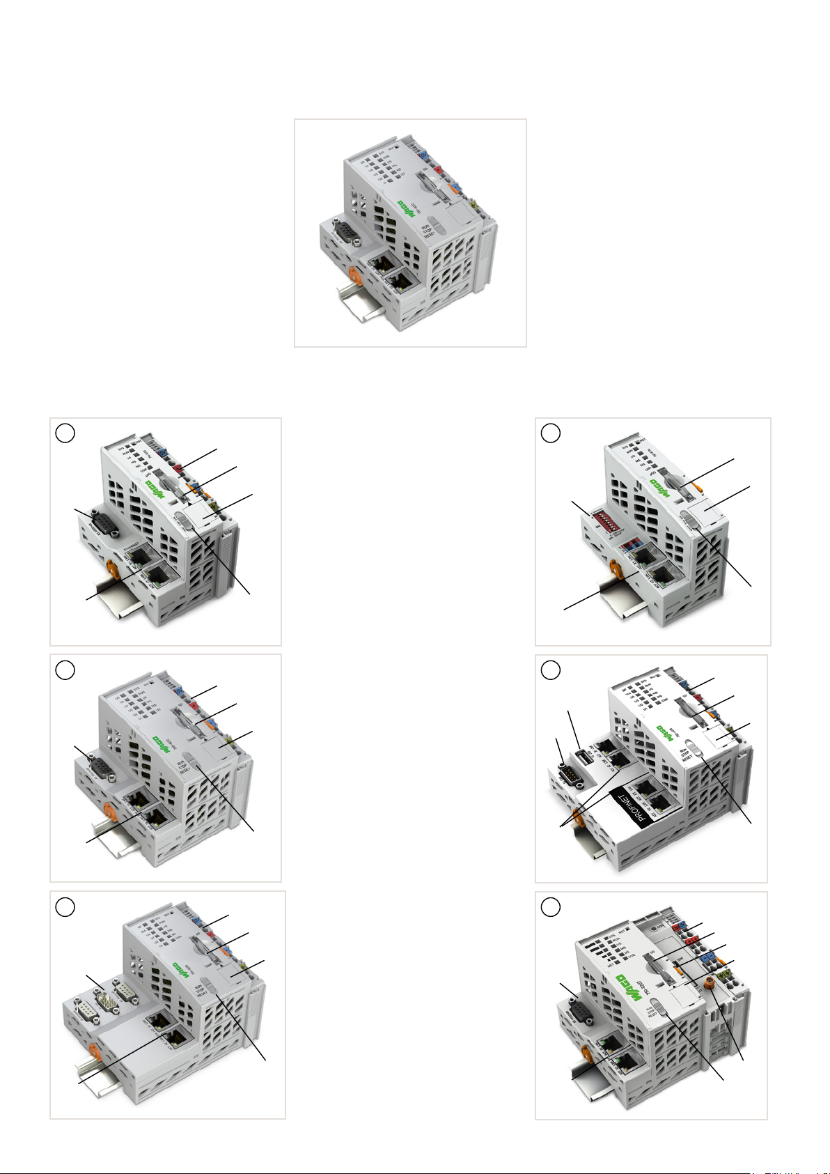
Interfaces and Types
A
b)
c)
C
b)
c)
E
b)
c)
a)
e)
d)
f)
a)
g)
d)
h)
a)
g)
d)
h)
• Including supply module to power downstream I/O
modules (a)
• Technical dierences on the connection level (b)
• ETHERNET 2 x RJ-45 (c)
• Service interface (d)
Housing design (A)
• microSD card slot for external storage media (e)
• Start/stop switch (f)
• W x H x D (mm) 61.5 x 71.9 x 100
• Connection technology (system/eld supply):
CAGE CLAMP®
• Conductor cross section: 0.08 … 2.5 mm²/28 … 14 AWG
Housing design (B)
• microSD card slot for external storage media (e)
• Start/stop switch (f)
• W x H x D (mm) 49.5 x 71.9 x 96.8
• Connection technology (system supply):
CAGE CLAMP®
• Conductor cross section: 0.08 … 1.5 mm²/28 … 16 AWG
Housing design (C)
• SD card slot for external storage media (g)
• Start/stop switch (h)
• W x H x D (mm) 78.6 x 71.9 x 100
• Connection technology (system/eld supply):
CAGE CLAMP®
• Conductor cross section: 0.08 … 2.5 mm²/28 … 14 AWG
Housing design (D)
• SD card slot for external storage media (g)
• Start/stop switch (h)
• ETHERNET 4 x RJ-45 (i)
• USB interface (j)
• W x H x D (mm) 112 x 71.9 x 100
• Connection technology (system/eld supply):
CAGE CLAMP®
• Conductor cross section: 0.08 … 2.5 mm²/28 … 14 AWG
Housing design (E)
• SD card slot for external storage media (g)
• Start/stop switch (h)
• W x H x D (mm) 112 x 71.9 x 100
• Connection technology (system/eld supply):
CAGE CLAMP®
• Conductor cross section: 0.08 … 2.5 mm²/28 … 14 AWG
Housing design (F)
• SD card slot for external storage media (g)
• Start/stop switch (h)
• GSM antenna connection(k)
• SIM card slot (l)
• W x H x D (mm) 102.5 x 71.9 x 100
• Connection technology (system/eld supply):
CAGE CLAMP®
• Conductor cross section: 0.08 … 2.5 mm²/28 … 14 AWG
Eco
The Eco version of the PFC200 limits the
number of stackable I/O modules to four.
Telecontrol Technology
The telecontrol technology versions of the
PFC200 are distinguished by their integrated,
standardized telecontrol technology:
• IEC 60870-5
• IEC 61850
• IEC 61400-25
• DNP3
B
e)
d)
b)
f)
c)
D
a)
g)
j)
d)
b)
i)
F
a)
h)
g)
l)
d)
b)
k)
c)
h)
Page 3

Controllers PFC100/PFC200
Installation Instructions
Power Supply
The internal electronics are powered by the
controller. The power supply to the eld-side
supply is electrically isolated. The division
enables a separate supply for sensors
and actuators. Snapping the I/O modules
together automatically routes the supply
voltages. Supply modules with diagnostics
enable additional monitoring of the power
supply. This conguration ensures a exible,
user-specic supply design for a station. The
current supply to the electronics is limited by
a maximum value. If the sum of the internal
current demand of all the I/O modules should
exceed this value, an additional system sup
ply module is necessary. Even in this case,
power supply to the eld-side supply of 10A
may not be exceeded. However, dierent
power supply modules allow a new power
supply, formation of potential groups and the
implementation of emergency stops.
-
PFC200
with
Supply Module
24 V
Electronics
Field potential 1
24 V
Bus Module
Supply Module
230 V
Field potential 2
24 V
Field potential 3
End Module
Item Number Key
Explanation of the components of an item
number key
Notes
Additional steps must be implemented based
on where the I/O system is installed:
Additionally, both a supply module and a
eld-side power supply lter are recom
mended when operating intrinsically safe Ex
Specic power and eld-side power supply
lters (750-624 or 750-626) are required for
marine and onshore/oshore applications.
A specic supply module (750-606) is
required to operate intrinsically safe Ex i
modules.
i modules for marine and onshore/oshore
applications.
As part of operating safety-related I/O modules, PELV/SELV power supply units must be
used for 24 VDC supply of electronics and
eld. In addition, specic power and eldside power supply lters must be provided
(750-626).
Please refer to the manual for details about
the power supply’s design.
Item No.: 750-81xx = PFC100
00: 2 x ETHERNET, Eco
01: 2 x ETHERNET
02: 2 x ETHERNET, RS-232/-485
Item No.: 750-82xy = PFC200
0y: Generation 1
1y: Generation 2
x2: 2 x ETHERNET, RS-232/-485
x3: 2 x ETHERNET, CAN
x4: 2 x ETHERNET, RS-232/-485, CAN
x5: 4 x ETHERNET, CAN, CANopen, USB
x6: 2 x ETHERNET, RS-232/-485, CAN, PROFIBUS-DP slave
x7: 2 x ETHERNET, RS-232/-485, mobile radio module
x8: 2 x ETHERNET, RS-232/-485, CAN, CANopen, PROFIBUS master
-
.../025-yyy: Extended temperature range of −20 ... +60°C
000: Standard
001: Telecontrol technology
002: Telecontrol Eco
Page 4

Controllers PFC100/PFC200
Standards and Rated Conditions
General Specications
Supply voltage (system) 24VDC (−25 … +30%)*;
Isolation 500 V (system/supply)
Surrounding air temperature (operation) 0 … +55 °C
Surrounding air temperature (operation) for
versions with an extended temperature range
Surrounding air temperature (storage) −40 … +85°C
Relative humidity 95% (non condensing)
Relative humidity for versions with an extended
temperature range
Operating altitude 0 … 2000 m
Pollution degree 2 per IEC 61131-2
Vibration resistance 0.5g (4g for all marine-certied controllers) per
Shock resistance 15g per IEC 60068-2-27
EMC immunity to interference Per EN 61000-6-2
EMC emission of interference Per EN 61000-6-3
Protection type IP20
Mounting type DIN-35 rail
Housing material Polycarbonate; polyamid 6.6
Exposure to pollutants Per IEC 60068-2-42 and IEC 60068-2-43
Permissible SO
a relative humidity < 75 %
Permissible H
a relative humidity < 75 %
Connection technology CAGE CLAMP®
Conductor cross sections; strip length
Standard PFC100/200
Conductor cross sections; strip length
PFC100 Eco
ent carrying capacity (power jumper
Curr
contacts)
contaminant concentration at
2
S contaminant concentration at
2
*for all marine-certied controllers
−20 … +60 °C
Max. 95 %, short-term condensation per Class
3K6 / IEC EN 60721-3-3 and E DIN 40046-721-3,
taking a temperature range of −20…+60 °C into
consideration (except wind-driven precipitation,
water and ice formation)
IEC 60068-2-6
25ppm
10ppm
0.08 … 2.5 mm²/28 … 14 A
8 … 9 mm / 0.31 … 0.35 inch
0.08 … 1.5 mm²/28 … 16 AWG;
5 … 6 mm / 0.2 … 0.24 inch
10 A
WG;
r
&
 Loading...