

Page 1

Pos: 2 /Do kumentation allgemein /Einband/ Einband H andbuch - De ckblatt o hne Varia ntenfeld (S tandard) @ 9\mod_1285229289866_0 .doc @ 64941 @ @ 1
Manual
WAGO-I/O-SYSTEM 750
2-Channel Analog Output Module 0-20 mA, Ex i
Pos: 3 /Alle Serien (Al lgemeine M odule)/H inweise zur Dokumen tation/Im pressum für Standard handbüch er - allg. Ang ab e n, A n sc hr i f ten, Telef on n u m mer n und E-Mail-A dressen @ 3\mod_1219151118203_21.doc @ 21060 @ @ 1
2AO 0-20mA Ex i
750-585
Version 1.1.0
Page 2

2 WAGO-I/O-SYSTEM 750
750-585 2AO 0-20mA Ex i
© 2012 by WAGO Kontakttechnik GmbH & Co. KG
All rights reserved.
WAGO Kontakttechnik GmbH & Co. KG
Hansastraße 27
D-32423 Minden
Phone: +49 (0) 571/8 87 – 0
Fax: +49 (0) 571/8 87 – 1 69
E-Mail: info@wago.com
Web: http://www.wago.com
=== Ende der Liste für Textmar ke Einband _vorne ===
Technical Support
Phone: +49 (0) 571/8 87 – 5 55
Fax: +49 (0) 571/8 87 – 85 55
E-Mail: support@wago.com
Every conceivable measure has been taken to ensure the accuracy and
completeness of this documentation. However, as errors can never be fully
excluded, we always appreciate any information or suggestions for improving the
documentation.
E-Mail: documentation@wago.com
We wish to point out that the software and hardware terms as well as the
trademarks of companies used and/or mentioned in the present manual are
generally protected by trademark or patent.
Manual
Version 1.1.0
Page 3

WAGO-I/O-SYSTEM 750 Table of Contents 3
750-585 2AO 0-20mA Ex i
Pos: 5 /Do kumentation allgemein /Verzeich nisse/Inh altsverzei chnis - ohn e Gl i e der ung - und V erzeichnis @ 3\mod_1219151230875_21.doc @ 21063 @ @ 1
Table of Contents
1 Notes about this Documentation ................................................................. 5
1.1 Validity of this Documentation ................................................................. 5
1.2 Copyright ................................................................................................... 5
1.3 Symbols ..................................................................................................... 6
1.4 Number Notation ....................................................................................... 8
1.5 Font Conventions ...................................................................................... 8
2 Important Notes ........................................................................................... 9
2.1 Legal Bases ............................................................................................... 9
2.1.1 Subject to Changes ............................................................................... 9
2.1.2 Personnel Qualifications ....................................................................... 9
2.1.3 Use of the 750 Series in Compliance with Underlying Provisions ...... 9
2.1.4 Technical Condition of Specified Devices ......................................... 10
2.2 Safety Advice (Precautions) .................................................................... 11
3 Device Description ..................................................................................... 13
3.1 View ........................................................................................................ 16
3.2 Connectors ............................................................................................... 17
3.2.1 Data Contacts/Internal Bus ................................................................. 17
3.2.2 Power Contacts/Field Supply ............................................................. 18
3.2.3 CAGE CLAMP® Connections ........................................................... 19
3.3 Display Elements .................................................................................... 20
3.4 Operating Elements ................................................................................. 20
3.5 Schematic Diagram ................................................................................. 21
3.6 Technical Data ........................................................................................ 22
3.6.1 Device data ......................................................................................... 22
3.6.2 Supply ................................................................................................. 22
3.6.3 Communication .................................................................................. 22
3.6.4 Outputs ............................................................................................... 22
3.6.5 Explosion Protection .......................................................................... 23
3.7 Approvals ................................................................................................ 24
3.8 Standards and Guidelines ........................................................................ 25
4 Mounting ..................................................................................................... 26
4.1 Assembly Sequence ................................................................................ 26
4.2 Inserting and Removing Devices ............................................................ 27
4.2.1 Inserting I/O Module .......................................................................... 27
4.2.2 Removing the I/O Module .................................................................. 28
5 Connect Devices ......................................................................................... 29
5.1 Connecting a Conductor to the CAGE CLAMP® ................................... 29
5.2 Connection Example ............................................................................... 30
6 Process Image ............................................................................................. 31
7 Use in Hazardous Environments .............................................................. 32
7.1 Marking Configuration Examples ........................................................... 33
7.1.1 Marking for Europe according to CENELEC and IEC ...................... 33
7.1.2 Marking for America according to NEC 500 ..................................... 36
Manual
Version 1.1.0
Page 4

4 Table of Contents WAGO-I/O-SYSTEM 750
750-585 2AO 0-20mA Ex i
7.2 Installation Regulations ........................................................................... 37
7.2.1 Special Conditions for Safe Operation of the ATEX and IEC Ex (acc.
DEMKO 08 ATEX 142851X and IECEx PTB 07.0064) ................... 38
7.2.2 Special conditions for safe use (ATEX Certificate TÜV 07 ATEX
554086 X) ........................................................................................... 39
7.2.3 Special conditions for safe use (IEC-Ex Certificate TUN 09.0001 X)41
7.2.4 ANSI/ISA 12.12.01 ............................................................................ 43
List of Figures ...................................................................................................... 45
List of Tables ........................................................................................................ 46
=== Ende der Liste für Textmar ke Verzeich nis_vorne ===
Manual
Version 1.1.0
Page 5

WAGO-I/O-SYSTEM 750 Notes about this Documentation 5
750-585 2AO 0-20mA Ex i
Pos: 7 /Alle Serien (Al lgemeine M odule)/Ü berschrift en für alle Serien/Hi nweis zur Dokument ationHinw eise zur Do kumentati on - Übersc hrift 1 @ 4\ mod_1237987661750_21.doc @ 29029 @ 1 @ 1
1 Notes about this Documentation
Pos: 8 /Alle Serien (Al lgemeine M odule)/H inweise zur Dokumen tation/Hin weis: Doku mentatio n aufbewahr en @ 4\mod_1237987339812_21.doc @ 29026 @ @ 1
Keep this documentation!
The operating instructions are part of the product and shall be kept for the entire
lifetime of the device. They shall be transferred to each subsequent owner or user
of the device. Care must also be taken to ensure that any supplement to these
instructions are included, if applicable.
Pos: 9 /Seri e 750 (WA GO-I/O-SYSTEM )/Hinwei se zur Do kumentation /Gültig keitsbereic h Dokument ation Bus klemme 750- xxxx, ohne Variantenangabe @ 4\mod_1237986650812_21.doc @ 29020 @ 2 @ 1
1.1 Validity of this Documentation
This documentation is only applicable to the I/O module 750-585
(2AO 0-20mA Ex i) of the WAGO-I/O-SYSTEM 750 series.
Pos: 10 /Ser ie 750 ( WAGO-I/O-SYST EM)/Hin weise zur D okumentatio n/Hinweis e/Achtung: Hinweis z ur Dokume ntation Bus klemmen 750- xxxx @ 4\mod_1237986979656_21.doc @ 29023 @ @ 1
The I/O module 750-585 shall only be installed and operated according to the
instructions in this manual and in the manual for the used fieldbus
coupler/controller.
Consider power layout of the WAGO-I/O-SYSTEM 750!
In addition to these operating instructions, you will also need the manual for the
used fieldbus coupler/controller, which can be downloaded at www.wago.com.
There, you can obtain important information including information on electrical
isolation, system power and supply specifications.
Pos: 11.1 /Al le Serie n (Allgemei ne Module) /Hinweis e zur Doku mentation/ Urhebersc hutz ausfü hrlich @ 4\ mod_1235565145234_21.doc @ 27691 @ 2 @ 1
1.2 Copyright
This Manual, including all figures and illustrations, is copyright-protected. Any
further use of this Manual by third parties that violate pertinent copyright
provisions is prohibited. Reproduction, translation, electronic and phototechnical
filing/archiving (e.g., photocopying) as well as any amendments require the
written consent of WAGO Kontakttechnik GmbH & Co. KG, Minden, Germany.
Non-observance will involve the right to assert damage claims.
Pos: 11.2 /Dokumentation allgemein/Gliederungselemente/---Seitenwechsel--- @ 3\mod_1221108045078_0.do c @ 21810 @ @ 1
Manual
Version 1.1.0
Page 6

6 Notes about this Documentation WAGO-I/O-SYSTEM 750
750-585 2AO 0-20mA Ex i
Pos: 11.3 /Al le Serie n (Allgemei ne Module) /Überschr iften für alle Serien /Hinweis z ur Dokum entation/S ymbole - Überschrift 2 @ 13\mod_1351068042408_21.doc @ 105270 @ 2 @ 1
1.3 Symbols
Pos: 11.4.1 /All e Serien (All g e meine Modul e) / Wi c htige Erläut erungen/ Si c h er h ei ts - und sonstig e Hinweis e/Gefahr /Gefahr: _War n ung vor Perso nenschäd e n al l g e mei n_ - Erläuterung @ 13\mod_1343309450020_21.doc @ 101029 @ @ 1
Personal Injury!
Indicates a high-risk, imminently hazardous situation which, if not avoided, will
result in death or serious injury.
Pos: 11.4.2 /All e Serien (All g e meine Modul e) / Wi c htige Erläut erungen/ Si c h er h ei ts - und sonstig e Hinweis e/Gefahr /Gefahr: _Warnung vor Personens chäden durch elekt rischen St rom_ - Erläuterung @ 13\mod_1343309694914_21.doc @ 101030 @ @ 1
Personal Injury Caused by Electric Current!
Indicates a high-risk, imminently hazardous situation which, if not avoided, will
result in death or serious injury.
Pos: 11.4.3 /Alle Ser ien (Allg emeine Mo dule)/Wic htige Erläut erungen/ Sicherheits - und sonsti ge Hinwei se/Warn ung/Warnung : _Warnung vor Pers onenschäd en allgem ein_ - Erläuterung @ 13\mod_1343309877041_21.doc @ 101035 @ @ 1
Personal Injury!
Indicates a moderate-risk, potentially hazardous situation which, if not avoided,
could result in death or serious injury.
Pos: 11.4.4 /All e Serien (All g e meine Modul e) / Wi c htige Erläut erungen/ Si c h er h ei ts - und sonstig e Hinweis e/Vorsic ht/Vorsicht : _Warnung vor Pers onenschä den allgemei n_ - Erläu ter ung @ 13\mod_1343310028762_21.do c @ 101038 @ @ 1
Personal Injury!
Indicates a low-risk, potentially hazardous situation which, if not avoided, may
result in minor or moderate injury.
Pos: 11.4.5 /All e Serien (All g e meine Modul e) / Wi c htige Erläut erungen/ Sicherheits - und sonstige Hinweise/Achtung/Achtun g: _Warnung vor Sachschäden allgemein_ - Erläu terung @ 13\mod_1343310134623_21.doc @ 101041 @ @ 1
Damage to Property!
Indicates a potentially hazardous situation which, if not avoided, may result in
damage to property.
Pos: 11.4.6 /All e Serien (All g e meine Modul e) / Wi c htige Erläut erungen/ Si c h er h ei ts - und sonstige Hinwe i se/Achtung/Achtung: _Warnung v or Sachschä den durch elektrost atische Aufl adung_ - Erläuterung @ 13\mod_1343310227702_21.doc @ 101044 @ @ 1
Damage to Property Caused by Electrostatic Discharge (ESD)!
Indicates a potentially hazardous situation which, if not avoided, may result in
damage to property.
Pos: 11.4.7 /All e Serien (All g e meine Modul e) / Wi c htige Erläut erungen/ Si c h er h ei ts - und sonstige Hinweise/Hinweis/Hinweis: _Wichtiger Hinweis allgemein_ - Eräuterung @ 13\mod_1343310326906_21.doc @ 101047 @ @ 1
Important Note!
Indicates a potential malfunction which, if not avoided, however, will not result in
damage to property.
Pos: 11.4.8 /All e Serien (All g e meine Modul e) / Wi c htige Erläut erungen/ Si c h er h ei ts - und sonstig e Hinweis e/Infor mation/Infor mation: _ Weitere Inf ormation allgemein_ - Erläuterung @ 13\mod_1343310439814_21.doc @ 101051 @ @ 1
Manual
Version 1.1.0
Page 7

WAGO-I/O-SYSTEM 750 Notes about this Documentation 7
750-585 2AO 0-20mA Ex i
Additional Information:
Refers to additional information which is not an integral part of this
documentation (e.g., the Internet).
Pos: 11.5 /Dokumentation allgemein/Gliederungselemente/---Seitenwechsel--- @ 3\mod_1221108045078_0.do c @ 21810 @ @ 1
Manual
Version 1.1.0
Page 8

8 Notes about this Documentation WAGO-I/O-SYSTEM 750
Table 1: Number Notation
Number code
Example
Note
Decimal
100
Normal notation
Hexadecimal
0x64
C notation
Binary
'100'
'0110.0100'
In quotation marks, nibble separated with
dots (.)
Table 2: Font Conventions
Font type
Indicates
italic
Names of paths and data files are marked in italic-type.
e.g.: C:\Programme\WAGO-I/O-CHECK
Menu
Menu items are marked in bold letters.
e.g.: Save
>
A greater-than sign between two names means the selection of a
e.g.: File > New
Input
Designation of input or optional fields are marked in bold letters,
e.g.: Start of measurement range
“Value”
Input or selective values are marked in inverted commas.
e.g.: Enter the value “4 mA” under Start of measurement range.
[Button]
Pushbuttons in dialog boxes are marked with bold letters in square
e.g.: [Input]
[Key]
Keys are marked with bold letters in square brackets.
e.g.: [F5]
750-585 2AO 0-20mA Ex i
Pos: 11.6 /Al le Serie n (Allgemei ne Module) /Hinweis e zur Doku mentation/ Zahlensys teme @ 3\mod_1221059454015_21.doc @ 21711 @ 2 @ 1
1.4 Number Notation
Pos: 11.7 /Al le Serie n (Allgemei ne Module) /Hinweis e zur Doku mentation/ Schriftko nventione n @ 3\mod_1221059521437_21.doc @ 21714 @ 2 @ 1
1.5 Font Conventions
Pos: 12 /Dokum e nt a ti o n al l g e mein/Glie der ungselem en te/---Seiten wechsel--- @ 3\mod_1221108045078_0.doc @ 21810 @ @ 1
menu item from a menu.
brackets.
Manual
Version 1.1.0
Page 9

WAGO-I/O-SYSTEM 750 Important Notes 9
750-585 2AO 0-20mA Ex i
Pos: 13 /All e Serien ( Allgemeine Module)/Ü berschrift en für al le Serien/ Wichtige Erläuterung enWichtig e Erläuter ungen - Üb erschrift 1 @ 4\mod_1241428899156_21.doc @ 32170 @ 1 @ 1
2 Important Notes
Pos: 14.1 /Al le Serie n (Allgemei ne Module) /Wichtig e Erläuteru ngen/Einl eitung Wic htige Erlä uterunge n @ 3\mod_1221059818031_21.d oc @ 21717 @ @ 1
This section includes an overall summary of the most important safety
requirements and notes that are mentioned in each individual section. To protect
your health and prevent damage to devices as well, it is imperative to read and
carefully follow the safety guidelines.
Pos: 14.2 /Al le Serie n (Allgemei ne Module) /Überschr iften für alle Serien /Wichtig e Erläuter ungenRechtl iche Gru ndlagen - Üb erschrift 2 @ 3\mod_1221060626343_21.doc @ 21726 @ 2 @ 1
2.1 Legal Bases
Pos: 14.3 /Al le Serie n (Allgemei ne Module) /Wichtig e Erläuteru ngen/Änd erungsvor behalt - Über schrift 3 und Inhalt @ 3\mod_1221060036484_21.doc @ 21720 @ 3 @ 1
2.1.1 Subject to Changes
WAGO Kontakttechnik GmbH & Co. KG reserves the right to provide for any
alterations or modifications that serve to increase the efficiency of technical
progress. WAGO Kontakttechnik GmbH & Co. KG owns all rights arising from
the granting of patents or from the legal protection of utility patents. Third-party
products are always mentioned without any reference to patent rights. Thus, the
existence of such rights cannot be excluded.
Pos: 14.4 /Serie 750 (WAGO-I/O-SYSTEM)/ Wi c ht i g e Er l ä ut erungen/P er s onalquali fi kation 750- xxxx @ 3\mod_1224061208046_21.doc @ 24063 @ 3 @ 1
2.1.2 Personnel Qualifications
All sequences implemented on Series 750 devices may only be carried out by
electrical specialists with sufficient knowledge in automation. The specialists
must be familiar with the current norms and guidelines for the devices and
automated environments.
All changes to the coupler or controller should always be carried out by qualified
personnel with sufficient skills in PLC programming.
Pos: 14.5 /Serie 750 (WAGO-I/O-SYSTEM)/ Wi c ht i g e Er l ä ut erungen/B es timmungs g e mäße Verwen d ung 7 50- xxxx @ 3\mod_1224064151234_21.d oc @ 24070 @ 3 @ 1
2.1.3 Use of the 750 Series in Complianc e wit h Unde rlying Provisions
Couplers, controllers and I/O modules found in the modular WAGO-I/OSYSTEM 750 receive digital and analog signals from sensors and transmit them
to the actuators or higher-level control systems. Using programmable controllers,
the signals can also be (pre-) processed.
The components have been developed for use in an environment that meets the
IP20 protection class criteria. Protection against finger injury and solid impurities
up to 12.5 mm diameter is assured; protection against water damage is not
ensured. Unless otherwise specified, operation of the components in wet and
dusty environments is prohibited.
Operating 750 Series components in home applications without further measures
is only permitted if they meet the emission limits (emissions of interference)
according to EN 61000-6-3. You will find the relevant information in the section
on "WAGO-I/O-SYSTEM 750" "System Description" "Technical Data" in
the manual for the used fieldbus coupler/controller.
Manual
Version 1.1.0
Page 10

10 Important Notes WAGO-I/O-SYSTEM 750
750-585 2AO 0-20mA Ex i
Appropriate housing (per 94/9/EG) is required when operating the WAGO-I/OSYSTEM 750 in hazardous environments. Please note that a prototype test
certificate must be obtained that confirms the correct installation of the system in
a housing or switch cabinet.
Pos: 14.6 /Alle Serien (Allgemeine Module)/Wichti ge Erläut erungen/T echnischer Zustand der Geräte - Ü berschrif t 3 und In halt @ 3\mod_1221060446109_21.doc @ 21723 @ 3 @ 1
2.1.4 Technical Condition of Spec ified Devices
The components to be supplied Ex Works, are equipped with hardware and
software configurations, which meet the individual application requirements.
WAGO Kontakttechnik GmbH & Co. KG will be exempted from any liability in
case of changes in hardware or software as well as to non-compliant usage of
components.
Please send your request for modified and new hardware or software
configurations directly to WAGO Kontakttechnik GmbH & Co. KG.
Pos: 14.7 /Dokumentation allgemein/Gliederungselemente/---Seitenwechsel--- @ 3\mod_1221108045078_0.do c @ 21810 @ @ 1
Manual
Version 1.1.0
Page 11
WAGO-I/O-SYSTEM 750 Important Notes 11
750-585 2AO 0-20mA Ex i
Pos: 14.8 /Al le Serie n (Allgemei ne Module) / Ü berschrift en für alle Ser i en / Wichtige Er l äu ter ungenSic herheitshi nweise - Üb erschrift 2 @ 6\mod_1260180299987_21.doc @ 46724 @ 2 @ 1
2.2 Safety Advice (Precautions)
Pos: 14.9 /Al le Serie n (Allgemei ne Module) /Wichtig e Erläuteru ngen/Sich erheits- und sonstige Hi nweise/Ei nleitung Si cherheits hinweise H ardware @ 6\mod_1260180170493_21.doc @ 46720 @ @ 1
For installing and operating purposes of the relevant device to your system the
following safety precautions shall be observed:
Pos: 14.10. 1 /Alle Ser ien (Allge meine Mo dule)/Wich tige Erläu terungen/Si cherheits - und sonsti ge Hinwei se/Gefahr/ Gefahr: N icht an Ger äten unter Spannung arbeite n! @ 6\mod_1260180365327_21.d oc @ 46727 @ @ 1
Do not work on components while energized!
All power sources to the device shall be switched off prior to performing any
installation, repair or maintenance work.
Pos: 14.10. 2 /Serie 75 0 (WAGO-I/O- SYSTEM)/ Wichtige Er läuterung en/Sicher heits- und sonstige Hinweise/Gefahr/Gefahr: Einbau 07 50-xxxx nur in Ge hä us en, Schrän ken oder elektr i s ch en Betriebsräumen! @ 6\mod_1260180556692_21.doc @ 46731 @ @ 1
Installation only in appropriate housings, cabinets or in electrical operation
rooms!
The WAGO-I/O-SYSTEM 750 and its components are an open system. As such,
install the system and its components exclusively in appropriate housings,
cabinets or in electrical operation rooms. Allow access to such equipment and
fixtures to authorized, qualified staff only by means of specific keys or tools.
Pos: 14.10. 3 /Alle Ser ien (Allge meine Mo dule)/Wich tige Erläu terungen/Si cherheits - und sonsti ge Hinwei se/Gefahr/ Gefahr: U nfallverh ütungsvors chriften b eachten! @ 6\mod_1260180657000_21.doc @ 46735 @ @ 1
Pos: 14.10. 4 /Alle Ser ien (Allge meine Mo dule)/Wich tige Erläu terungen/Si cherheits - und sonsti ge Hinwei se/Gefahr/ Gefahr: A uf normg erechten Ans chluss ac hten! @ 6\ mod_1260180753479_21.doc @ 46739 @ @ 1
Pos: 14.11. 1 /Alle Ser ien (Allge meine Mo dule)/Wich ti g e E r läu terungen /Si c herheits- und sonstige Hinwe i se/Achtung/Achtu ng: Defekte oder beschä digte Geräte austauschen! @ 6\mod_1260180857358_21.doc @ 46743 @ @ 1
Replace defective or damaged devices!
Replace defective or damaged device/module (e.g., in the event of deformed
contacts), since the long-term functionality of device/module involved can no
longer be ensured.
Pos: 14.11. 2 /Alle Ser ien (Allge meine Mo dule)/Wich tige Erläut erungen/Si cherheits - und sonsti ge Hinwei se/Achtu ng/Achtung: Geräte vor krieche nden und is olierend en Stoffen s chützen! @ 6\mod_1260181036216_21.doc @ 46747 @ @ 1
Protect the components against materials having seeping and insulating
properties!
The components are not resistant to materials having seeping and insulating
properties such as: aerosols, silicones and triglycerides (found in some hand
creams). If you cannot exclude that such materials will appear in the component
environment, then install the components in an enclosure being resistant to the
above-mentioned materials. Clean tools and materials are imperative for handling
devices/modules.
Pos: 14.11. 3 /Alle Ser ien (Allge meine Mo dule)/Wich tige Erläu terungen/Si cherheits - und sonsti ge Hinwei se/Achtu ng/Achtung: Reinigu ng nur mit z ulässige n Materiali en! @ 6\mod_1260181203293_21.doc @ 4675 1 @ @ 1
Cleaning only with permitted materials!
Clean soiled contacts using oil-free compressed air or with ethyl alcohol and
leather cloths.
Pos: 14.11. 4 /Alle Ser ien (Allge meine Mo dule)/Wich tige Erläu terungen/Si cherheits - und sonsti ge Hinwei se/Achtu ng/Achtung: Kein Ko ntaktspray verwenden! @ 6\mod_1260181290808_21.doc @ 46755 @ @ 1
Manual
Version 1.1.0
Page 12

12 Important Notes WAGO-I/O-SYSTEM 750
750-585 2AO 0-20mA Ex i
Do not use any contact spray!
Do not use any contact spray. The spray may impair contact area functionality in
connection with contamination.
Pos: 14.11. 5 /Alle Ser ien (Allge meine Mo dule)/Wich tige Erläu terungen/Si cherheits - und sonsti ge Hinwei se/Achtu ng/Achtung: Verpolung vermeide n! @ 6\mod_1260184045744_21.doc @ 46767 @ @ 1
Do not reverse the polarity of connection lines!
Avoid reverse polarity of data and power supply lines, as this may damage the
devices involved.
Pos: 14.11. 6 /Alle Ser ien (Allge meine Mo dule)/Wich tige Erläu terungen/Si cherheits - und sonsti ge Hinwei se/Achtu ng/Achtung: Elektrost atische E ntladung vermeiden! @ 6\mod_1260181364729_21.doc @ 46759 @ @ 1
Avoid electrostatic discharge!
The devices are equipped with electronic components that you may destroy by
electrostatic discharge when you touch. Pay attention while handling the devices
to good grounding of the environment (persons, job and packing).
Pos: 15 /Dokum e nt a ti o n al l g e mein/Glie der ungselem en te/---Seiten wechsel--- @ 3\mod_1221108045078_0.doc @ 21810 @ @ 1
Manual
Version 1.1.0
Page 13

WAGO-I/O-SYSTEM 750 Device Description 13
750-585 2AO 0-20mA Ex i
Pos: 16 /All e Serien ( Allgemeine Module)/Ü berschrift en für all e Serien/G erätebesc hreibungG erätebesc hreibung - Ü berschrift 1 @ 3\mod_1233756084656_21.doc @ 27096 @ 1 @ 1
3 Device Description
Pos: 17.1 /Serie 750 (WAGO-I/O-SYSTEM)/G erätebesc hreibung/Ei nleitung /Anwendung /AO/Anwendung 750-05xx AO Ex i Zon e 1 (0...2 0mA) @ 12 \mod_1337840585706_21.doc @ 95483 @ @ 1
The analog output module 750-585 (2AO 0-20mA Ex i) generates a standardized
signal of 0 … 20 mA for hazardous field area of zone 1.
Pos: 17.2 /Serie 750 (WAGO-I/O-SYSTEM)/ Wi c ht i g e Er l ä ut erungen/Si c herheits- und sonstige Hi n w ei s e/ Warnung War nung: Ex i Instal l ation des WAG O-I/O-SYST EM 750 nur i n Zone 2 o der im nic ht-ex-Bereich @ 5\mod_1245851655116_21.doc @ 359 47 @ @ 1
Installation only in zone 2 or in non-hazardous environments!
The installation of the WAGO-I/O-SYSTEM 750 fieldbus couplers/ controllers
and I/O modules is only to be done in zone 2 or in non-hazardous environments.
Pos: 17.3 /Serie 750 (WAGO-I/O-SYSTEM)/G erätebesc hreibung/Ei nleitung /I/O-Beschr eibung/A O/I/O-Beschr eibung 750- 05xx 2 AO 2-Leit er (A O und 0V) @ 5\mod _1247048703979_21.doc @ 36857 @ @ 1
The module has two output channels and enables, for example, the direct wiring
of two 2-conductor actuators. The output signals are connected to the CAGE
Pos: 17.4 /S erie 750 (WAGO-I/O-SYSTEM )/Geräteb eschreibu ng/Einleit ung/I/O-B eschreibung /AO/I/O-Bes chreibung 7 50-05xx AO Gemeinsa mer Schir manschluss @ 12\mod_1337841659376_21.doc @ 95495 @ @ 1
Pos: 17.5 /Serie 750 (WAGO-I/O-SYSTEM)/Geräte beschreibu ng/Einleit ung/I/O-B eschreibu ng/Allgemei n/Verweis auf Kapi tel "Anschl üsse" @ 8\ mod_1276775378035_21.doc @ 57956 @ @ 1
Pos: 17.6 /Serie 750 (WAGO-I/O-SYSTEM)/G erätebesc hreibung/Ei nleitung /I/O-Beschr eibung/All gemein/V erweis auf Kapitel "G eräte ansc hließen - A nschlussb ei s pi el(e)" @ 5\mod_1246015203281_21.doc @ 36298 @ @ 1
CLAMP® connections AO 1 and 0V or AO 2 and 0V.
The output channels of this module have a common shield (screen) connection.
The assignment of the connections is described in the "Connections" section.
Connection examples are in the "Connecting devices - connection examples"
section.
Pos: 17.7 /Serie 750 (WAGO-I/O-SYSTEM)/G erätebesc hreibung/Ei nleitung /LED-Anzei ge/LED Zu stand Betr ieb @ 5\mod_1245391732046_21.doc @ 35668 @ @ 1
The "ready" state of the respective channel and the internal data communication is
Pos: 17.8 /Serie 750 (WAGO-I/O-SYSTEM)/G erätebesc hreibung/Ei nleitung /LED-Anzei g e/ Verweis auf Ka pi t el "Anzeigeel emente" @ 5\ mod_1246010525000_21.doc @ 36194 @ @ 1
indicated by a green function LED.
The meaning of the LEDs is described in the “Display Elements” section.
Pos: 17.9 /Serie 750 (WAGO-I/O-SYSTEM)/ Wi c ht i g e Er l ä ut erungen/Si c herheits- und sonstige Hi n w ei s e/ Warnung/ War nung: Ex-i-Ei nspeisung n ur mit Ex-i-Einspeiseklemme + Abbildung @ 4\mod_1241505512875_21.doc @ 32293 @ @ 1
Ex i I/O modules shall only be supplied via Ex i 24VDC power supply
module!
Ex i I/O modules shall only be operated with an Ex i 24VDC power supply
module (see figure below).
Manual
Version 1.1.0
Page 14

14 Device Description WAGO-I/O-SYSTEM 75 0
750-585 2AO 0-20mA Ex i
Figure 1: Suppl y Princip le Ex i
Pos: 17.10 / Serie 750 ( WAGO-I/O-SY STEM)/G erätebeschr eibung/Ei nleitung/ Versorgung /Versorg ung 24 V, 0 V über Leis tungskont akte Ex i @ 4\mod_1242218496140_21.doc @ 33110 @ @ 1
The Ex i I/O module receives the 24V voltage supply for the field level from an
upstream Ex i I/O module or from an Ex i power supply module via the power
contacts used as blade contacts. It then provides this potential to subsequent I/O
modules via the power contacts used as spring contacts.
Pos: 17.11 / Serie 750 ( WAGO-I/O-SY STEM)/Wi chtige Erl äuterung en/Sicherhei ts- und sonstige Hinweise/HinweisHinweis: M aximaler Strom Ex i Einspeisu ng 750-06 xx 1,0 A @ 7 \mod_1274358256668_21.doc @ 56898 @ @ 1
Do not exceed maximum current via power contacts!
The maximum current available from the 750-606 or 750-625/000-001 Ex-i
Supply Module is 1 A.
When configuring the system, ensure that this current is not exceeded. If
exceeded, an additional potential feed module must be used.
Pos: 17.12 / Serie 750 ( WAGO-I/O-SY STEM)/Wi chtige Erl äuterung en/Sicherhei ts- und sonstige Hinweise/Warnung/Warnung: Ex i Luft- und Kriechs tr ec ken einhal ten @ 4\mod_1241505101078_21.doc @ 32290 @ @ 1
Keep the air and creep distances between intrinsically safe segments!
The maximum current available from the 750-606 or 750-625/000-001 Ex-i
Supply Module is 1 A.
If the employment of further DC 24 V Ex i Supply modules is necessary for
reasons of extent of utilization, four Separation modules (750-616) must be used
to guarantee the distance between the intrinsically safe segments.
Pos: 17.13 / Serie 750 ( WAGO-I/O-SY STEM)/G erätebeschr eibung/Ei nleitung/ Versorgung /Galvanisc he Trennu ng Feld/S ystem @ 3\ mod_1233756478750_21.doc @ 27102 @ @ 1
The field voltage and the system voltage are electricall y isolated fro m each ot her.
Pos: 17.14 / Serie 750 ( WAGO-I/O-SY STEM)/G erätebeschr eibung/Ei nleitung/ Versorgung /Anordnu ng in Ex i-Seg ment beli ebig @ 4\ mod_1241506600 203_21.doc @ 32297 @ @ 1
Manual
Version 1.1.0
Page 15

WAGO-I/O-SYSTEM 750 Device Description 15
750-585 2AO 0-20mA Ex i
Any configuration of the input modules is possible within an intrinsically safe
segment when configuring the fieldbus node. An arrangement in groups within the
group of potentials is not necessary.
Pos: 17.15 / Serie 750 ( WAGO-I/O-SY STEM)/G er ät e beschreib ung / Einleitung /Einsatz b er ei c h/Einsat zb er ei c h 750-xxxx al le K o p pl er /C ontroll er oh ne Ec onomy-Ko ppler @ 3\ mod_1232541867468_21.doc @ 26525 @ @ 1
The I/O module 750-585 can be used with all fieldbus couplers/controllers of the
WAGO-I/O-SYSTEM 750 (except for the economy types 750-320, -323, -324
and -327).
Pos: 17.16 / Serie 750 ( WAGO-I/O-SY STEM)/Wi chtige Erl äuterung en/Sicherhei ts- und son stige Hin weise/Infor mationInf ormation: Allgemei ne Informa tionen zu Ex i @ 4\mod_1241507736531_21.doc @ 32301 @ @ 1
Further Information about explosion prevention!
General information to the explosion prevention is in the manual chapter
"Use in Hazardous Environments" described!
Pos: 18 /Dokum e nt a ti o n al l g e mein/Glie der ungselem en te/---Seiten wechsel--- @ 3\mod_1221108045078_0.doc @ 21810 @ @ 1
Manual
Version 1.1.0
Page 16

16 Device Description WAGO-I/O-SYSTEM 75 0
Table 3: Caption acc. to figure “View“
No.
Designation
Description
Details see chapter
Marking possibility with
Mini-WSB
„Device Description“ >
„Display elements“
„Device Description“ >
„Connections“
CAGE CLAMP®- supplies
supply 0 V and Shield
„Device Description“ >
„Connections“
„Assembly“ > „Insert and
delete Device“
„Device Description“ >
„Connections“
750-585 2AO 0-20mA Ex i
Pos: 19 /All e Serien ( Allgemeine Module)/Ü berschrift en für all e Serien/G erätebesc hreibungA nsicht - Über schrift 2 @ 4\mod_1240984217343_21.doc @ 31958 @ 2 @ 1
3.1 View
Pos: 20 /Ser ie 750 ( WAGO-I/O-SYST EM ) / Gerätebes c hr ei bung/Ansi c ht/Analog a usgangs kle m m en / A ns ic ht 750-0585 @ 5\mod_1246000383312_21.doc @ 36128 @ @ 1
Figure 2: View
Pos: 21 /Dokum e nt a ti o n al l g e mein/Glie der ungselem en te/---Seiten wechsel--- @ 3\mod_1221108045078_0.doc @ 21810 @ @ 1
1 ---
2 A, E Status-LEDs
3 --- Data contacts
4 1, 3, 4, 5, 7, 8
Outputs AO 1, AO 2, Field
5 --- Power jumper contacts +24 V
6 --- Release clip
7 --- Power jumper contacts 0 V
---
„Technical manual “ >
„Connections“
Manual
Version 1.1.0
Page 17

WAGO-I/O-SYSTEM 750 Device Description 17
750-585 2AO 0-20mA Ex i
Pos: 22 /All e Serien ( Allgemeine Module)/Ü berschrift en für al le Serien/G erätebesc hreibung Anschlüss e - Überschri ft 2 @ 4\mod_1240984262656_21.doc @ 31961 @ 2 @ 1
3.2 Connectors
Pos: 23 /Ser ie 750 ( WAGO-I/O-SYSTEM)/Gerätebeschreibung/Anschlüsse/Datenkontakte/Klemmenbus - Überschrift 3 @ 6\ mod_1256294684083_21.doc @ 43660 @ 3 @ 1
3.2.1 Data Contacts/Internal Bus
Pos: 24.1 /Serie 750 (WAGO-I/O-SYSTEM)/Gerätebeschreibung/Anschlüsse/Datenkontakte @ 3\mod_1231771259187_21.doc @ 26002 @ @ 1
Communication between the coupler/controller and the bus modules as well as the
system supply of the bus modules is carried out via the internal bus. It is
comprised of 6 data contacts, which are available as self-cleaning gold spring
contacts.
Figure 3: Data contacts
Pos: 24.2 /Serie 750 (WAGO-I/O-SYSTEM)/ Wi c ht i g e Er l ä ut erungen/Si c herheits- und sonstige Hi n w ei s e/ A c h tu ng/Achtu ng : Bus klemmen ni c ht a uf G ol dfederkon t a k te leg e n! @ 7\mod_1266318463636_21.doc @ 50695 @ @ 1
Do not place the I/O modules on the gold spring contacts!
Do not place the I/O modules on the gold spring contacts in order to avoid soiling
or scratching!
Pos: 24.3 /Serie 750 (WAGO-I/O-SYSTEM)/ Wi c ht i g e Er l ä ut erungen/Si c herheits- und sonstige Hinweise/Achtung/Achtung: ESD - Auf gut e Erdung der Umgebu ng achten! @ 7\mod_1266318538667_21.doc @ 50708 @ @ 1
Ensure that the environment is well grounded!
The modules are equipped with electronic components that may be destroyed by
electrostatic discharge. When handling the modules, ensure that the environment
(persons, workplace and packing) is well grounded. Avoid touching conductive
components, e.g. data contacts.
Pos: 25 /Dokumentation allgemein/Gliederungselemente/---Seitenwechsel --- @ 3\mod_1221108045078_0.doc @ 21810 @ @ 1
Manual
Version 1.1.0
Page 18

18 Device Description WAGO-I/O-SYSTEM 75 0
Table 4: Power jumper contacts
jumper contacts
Connection
Type
Number
Function
750-585 2AO 0-20mA Ex i
Pos: 26 /Ser ie 750 ( WAGO-I/O-SYST EM)/Gerät ebeschrei bung/Ansc hlüsse/Leis tungskont akte/Feld versorgung - Überschr i ft 3 @ 6\ mod_1256294692864_21.doc @ 43664 @ 3 @ 1
3.2.2 Power Contacts/Fiel d S upply
Pos: 27.1 /Serie 750 (WAGO-I/O-SYSTEM)/ Wi c ht i g e Er l ä ut erungen/Si c herheits- und sonstig e Hinweis e/Vorsicht /Vorsicht : Verletz ungsgefahr durch sch arfkantig e Messerko ntakte! @ 6\mod_1256193279401_21.doc @ 43414 @ @ 1
Risk of injury due to sharp-edged male contacts!
The male contacts are sharp-edged. Handle the module carefully to prevent injury.
Pos: 27.2 /Serie 750 (WAGO-I/O-SYSTEM)/G erätebesc hreibung/A nschlüsse /Leistung skontakte 2 LK (Mess er/Feder) @ 7\mod_1266317883167_21.doc @ 50688 @ @ 1
The I/O module 750-585 has 2 self-cleaning power jumper contacts that supply
and transmit power for the field side. The contacts on the left side of the I/O
module are designed as male contacts and the contacts on the right side as spring
contacts.
Figure 4: Power
Pos: 27.3 /Serie 750 (WAGO-I/O-SYSTEM)/ Wi c ht i g e Er l ä ut erungen/Si c herheits- und sonstige Hinweise/HinweisHinweis: Maximaler Strom Ex i Einspeisung 750-06xx 1,0 A @ 7\mod_1274358256668_21.doc @ 56898 @ @ 1
Do not exceed maximum current via power contacts!
The maximum current available from the 750-606 or 750-625/000-001 Ex-i
Supply Module is 1 A.
When configuring the system, ensure that this current is not exceeded. If
exceeded, an additional potential feed module must be used.
Infeed of the field
1 Blade cont act 2
supply voltage
(UV and 0 V)
Forwarding of the
2 Spring contact 2
field supply voltage
(UV and 0 V)
Pos: 28 /Dokum e nt a ti o n al l g e mein/Glie der ungselem en te/---Seiten wechsel--- @ 3\mod_1221108045078_0.doc @ 21810 @ @ 1
Manual
Version 1.1.0
Page 19

WAGO-I/O-SYSTEM 750 Device Description 19
Table 5: Connections
Connection
Channel
Designation
Function
Power
contacts
Power
contacts
750-585 2AO 0-20mA Ex i
Pos: 29 /Ser ie 750 ( WAGO-I/O-SYST EM)/Gerät ebeschrei bung/Ansc hlüsse/CA GE CLAMP-An schlüsse - Ü berschrift 3 @ 6\mod_1256296337770_21.doc @ 43674 @ 3 @ 1
3.2.3 CAGE CLAMP® Connections
Pos: 30 /Ser ie 750 ( WAGO-I/O-SYST EM ) / Gerätebes c hr ei bung/Ansc hlüsse/A n al og a usgangs kle m m e n/ Anschlüss e 750-0585 @ 5\mod_1246000463671_21.doc @ 36140 @ @ 1
Pos: 31 /Dokum e nt a ti o n al l g e mein/Glie der ungselem en te/---Seiten wechsel--- @ 3\mod_1221108045078_0.doc @ 21810 @ @ 1
Fig. 5: Connections
1
4 0 V Output AO 1: Actor supply 0 V
1
AO 1 Output AO 1: Signal voltage
5 S Output AO 1: Shield
5
7 0 V Output AO 2: Actor supply 0 V
2
AO 2 Output AO 2: Signal voltage
8 S Output AO 2: Shie ld connection
jumper
jumper
- +24 V Field supply 24 V
- 0 V Field supply 0 V
Manual
Version 1.1.0
Page 20

20 Device Description WAGO-I/O-SYSTEM 75 0
Table 6: Display elements
Desig-
nation
No operational readiness or the
interrupted
Operational readiness and troublefree internal data bus communication
No operational readiness or the
interrupted
Operational readiness and troublefree internal data bus communication
750-585 2AO 0-20mA Ex i
Pos: 32 /All e Serien ( Allgemeine Module)/Ü berschrift en für al le Serien/G erätebesc hreibung Anzeigeele mente - Über schrift 2 @ 4\mod_1240984390875_21.doc @ 31964 @ 2 @ 1
3.3 Display Elements
Pos: 33 /Ser ie 750 ( WAGO-I/O-SYST EM ) / Gerätebes c hr ei bung/Anz ei g eelemente /Analoga usg angsklem m en / A nz eigeelem ent e 750-05xx Ex 2AO (Ag n, Cgn) @ 5\mod_1246000589437_21.doc @ 36152 @ @ 1
LED Channel
A 1
Figure 6: Display
elements
E 2
Pos: 34 /All e Serien ( Allgemeine Module)/Ü berschrift en für al le Serien/G erätebesc hreibung Bedienelem ente - Übers c hrift 2 @ 4\mod_1239191655456_21.doc @ 30439 @ 2 @ 1
3.4 Operating Elements
Pos: 35 /Ser ie 750 ( WAGO-I/O-SYST EM)/Gerät ebeschrei bung/Bedie nelemente/ Bedienele mente Bus klemme 75 0-xxxx nic ht vorhand en @ 4\mod_1236322031125_21.doc @ 28063 @ @ 1
The I/O module 750-585 has no operating elements.
Pos: 36 /Dokum e nt a ti o n al l g e mein/Glie der ungselem en te/---Seiten wechsel--- @ 3\mod_1221108045078_0.doc @ 21810 @ @ 1
State
AO 1
State
AO 2
State Function
off
internal data bus communication is
green
off
internal data bus communication is
green
Manual
Version 1.1.0
Page 21

WAGO-I/O-SYSTEM 750 Device Description 21
750-585 2AO 0-20mA Ex i
Pos: 37 /Alle Seri en (Allge mei ne Module)/Ü ber s chriften für al l e S erien/Gerä tebeschr ei b u ng S c he matisches Sc h al t bi l d - Ü b er s c hr i f t 2 @ 4\ mod_12409844413 12_21.doc @ 31967 @ 2 @ 1
3.5 Schematic Diagram
Pos: 38 /Ser ie 750 ( WAGO-I/O-SYST EM ) / Gerätebes c hr ei bung/Sch e matische Sc hal tbilder/ A nal ogausga ng s klemmen/Sc hematisch es Schaltbil d 75 0-0585 @ 5\mod_1246000661796_21.doc @ 36164 @ @ 1
Fig. 7: Schematic diagram
Pos: 39 /Dokum e nt a ti o n al l g e mein/Glie der ungselem en te/---Seiten wechsel--- @ 3\mod_1221108045078_0.doc @ 21810 @ @ 1
Manual
Version 1.1.0
Page 22

22 Device Description WAGO-I/O-SYSTEM 75 0
Table 7: Technical data device
Width
24 mm
Height (from upper edge of 35 DIN rail)
64 mm
Depth
100 mm
Weight
ca. 91,6 g
Table 8: Technical data supply
Voltage supply
Via system voltage terminal bus (5 V
DC) and power contacts (24 V DC)
Current consumption
. (internal).
(5 V DC)
21 mA
Input current
. (Field).
(24 V DC)
19 mA / Module + Load (2 x 20 mA)
Voltage via power jumper contacts
24 V DC (Supply via Ex i-supply
module)
Current via power contacts
500 mA/1000 mA (depending on Ex isupply module)
Power loss PV
0.9 W
Power consumption P
max.
1.5 W
Isolation (Peak value)
375 V System/Supply
Table 9: Technical data communication
Internal bit width (Terminal bus)
2 x 16 Bit data,
2 x 8 Bit Control/Status (optional)
Table 10: Technical data inputs
No. of outputs
2
Signal current
0 mA ... 20 mA
Load
< 500 Ω
Linearity
±2 LSB
Resolution
12 Bit
Conversion time
< 2 ms
Output error 25°C
< ±0,2 % from full scale range
Temperature coefficient
< ±0,01 % / K from full scale range
750-585 2AO 0-20mA Ex i
Pos: 40 /All e Serien ( Allgemeine Module)/Ü berschrift en für al le Serien/G erätebesc hreibung Technisch e Daten - Üb er sc hrift 2 @ 3\mod_1232967587687_21.doc @ 26924 @ 2 @ 1
3.6 Technical Data
Pos: 41 /Ser ie 750 ( WAGO-I/O-SYST EM)/Gerät ebeschrei bung/Techni sche Date n/Analoga usgangs klemmen/Tec hnische Dat en 750-05 85 @ 5\ mod_1245995273093_21.doc @ 36080 @ 33333 @ 1
3.6.1 Device data
3.6.2 Supply
typ
typ
3.6.3 Communication
3.6.4 Outputs
max.
Manual
Version 1.1.0
Page 23

WAGO-I/O-SYSTEM 750 Device Description 23
Table 11: Technical data Explosion Protection
Ex directive 94/9/EG
EN 60079-0:2006, EN 60079-11:2007,
EN 61241-1:2004, EN61241-11:2006
Safety Data electric circu it
U0 = 27,3 V
Line characteristic: linear
Reactance without
L0
C0
Ex ib IIC
11 mH
88 nF
Ex ib IIB
56 mH
680 nF
Ex ib I
110 mH
3,5 µF
Reactance with
L0
C0
Ex ib II C
≤ 0,2 mH
87 nF
0,5 mH
77 nF
1,0 mH
63 nF
2,0 mH
51 nF
7,6 mH
40 nF
Ex ib II B
≤ 0,1 mH
0,67 µF
0,5 mH
0,46 µF
1,0 mH
0,39 µF
20,0 mH
0,31 µF
44,0 mH
0,23 µF
Ex ib I
0,01 mH
1,8 µF
0,05 mH
1,1 µF
0,2 mH
0,68 µF
1,0 mH
0,43 µF
5,0 mH
0,29 µF
750-585 2AO 0-20mA Ex i
3.6.5 Explosion Protection
EN 60079-15:2005, EN 61241-0:2006,
I0 = 57,5mA
P0 = 392 mW
consideration of the
simultaneousness
consideration of the
simultaneousness
Pos: 42 /Dokum e nt a ti o n al l g e mein/Glie der ungselem en te/---Seiten wechsel--- @ 3\mod_1221108045078_0.doc @ 21810 @ @ 1
Manual
Version 1.1.0
Page 24

24 Device Description WAGO-I/O-SYSTEM 75 0
Conformity Marking
TÜV
07 ATEX 554086 X
I (M2) [Ex ia] I
II 3 (1) D Ex tD [iaD] A22 IP6X T135°C
Permissible operation temperature:
0 °C ≤ T
A
≤ +60 °C
TÜV
TUN 09.0001X
[Ex ia] I
Ex tD [iaD] A22 IP6X T135°C
Permissible operation temperature:
0 °C ≤ T
A
≤ +60 °C
CULUS
ANSI/ISA 12.12.01
Class I, Div2 ABCD T4
750-585 2AO 0-20mA Ex i
Pos: 43 /All e Serien ( Allgemeine Module)/Ü berschrift en für al le Serien/G erätebesc hreibung Zulassunge n - Überschr ift 2 @ 3\ mod_1224055364 109_21.doc @ 24030 @ 2 @ 1
3.7 Approvals
Pos: 44 /Ser ie 750 ( WAGO-I/O-SYST EM ) / Gerätebes c hr ei bung/Zul as s u ngen/Infor m at i on: Weiter e Inf ormatione n z u Zul assungen 750- xxxx @ 3\mod_1227190967156_21.doc @ 25221 @ @ 1
More Information about Approvals
Detailed references to the approvals are listed in the document "Overview
Approvals WAGO-I/O-SYSTEM 750", which you can find on the DVD
“AUTOMATION Tools and Docs” (order no. 0888-0412) or via the internet
under: www.wago.com Documentation WAGO-I/O-SYSTEM 750
System Description.
Pos: 45 /Ser ie 750 ( WAGO-I/O-SYST EM)/Gerät ebeschrei bung/Zulass ungen/Z ulassunge n Busklem me 750-xxxx Al lg emein, ohne V arianten ang abe - Einleit ung @ 4\mod_1237460656921_21.doc @ 28643 @ @ 1
The following approvals have been granted to 750-585 I/O modules:
Pos: 46.1 /Al le Serie n (Allgemei ne Module) /Zulassu ngen/Stan dardzulass ungen/CE ( Konformit ätskennzei chnung) @ 3\mod_1224494777421_2 1.doc @ 24276 @ @ 1
Pos: 46.2 /Al le Serie n (Allgemei ne Module) /Zulassu ngen/Stan dardzulass ungen/cUL us (UL508) @ 3\mod_1224055013140_0.doc @ 24020 @ @ 1
Pos: 46.3 /Dokumentation allgemein/Gliederungselemente/------Leerzeile------ @ 3\mod_1224662755687_0.doc @ 24460 @ @ 1
Pos: 47 /Ser ie 750 ( WAGO-I/O-SYST EM)/Gerät ebeschrei bung/Zulass ungen/Z ulassunge n Busklem me 750-xxxx Ex, ohne Variantenanga be - Einleitung @ 4\mod_1237191218000_21.doc @ 28423 @ @ 1
The following Ex approvals have been granted to 750-585 I/O modules:
Pos: 48.1 /Alle Serien (Allgemeine Module)/Zulassungen/Ex Zulassungen/TÜV (07 ATEX 554086 X) I (M2) [Ex ia] I II 3 (1) G Ex nA [ia] IIC T4 II 3 (1) D Ex tD [iaD] A 22 @ 5\mod_1245299573015_0.doc @ 35528 @ @ 1
Pos: 48.2 /All e Ser i e n (Allgemei ne Modul e)/Zulassu ngen/Ex Z ulassunge n/Ergänzu ng Betriebs temperatur 0 °C <= T A <= +60 °C @ 9\mod_1295605895541_21.doc @ 68610 @ @ 1
Pos: 48.3 /Alle Serien (Allgemeine Module)/Zulassungen/Ex Zulassungen/TÜV (TUN 09.001X) [Ex ia] I Ex nA [ia] IIC T4 Ex tD [iaD] A22 IP6X T135°C @ 5\mod_1245299576890_0.doc @ 35532 @ @ 1
CULUS
II 3 (1) G Ex nA [ia] IIC T4
Ex nA [ia] IIC T4
UL508
Pos: 48.4 /Al le Serie n (Allgemei ne Module) /Zulassu ngen/Ex Zul assungen/ Ergänzung Betriebs temperatur 0 °C <= TA <= +60 °C @ 9\mod_1295605895541_21.doc @ 68610 @ @ 1
Pos: 48.5 /Alle Serien (Allgemeine Module)/Zulassungen/Ex Zulassungen/cULus (ANSI/ISA 12.12.01) Class I, Div2 ABCD T4 @ 3\mod_1224054791812_0.doc @ 24014 @ @ 1
Pos: 48.6 /Dokumentation allgemein/Gliederungselemente/------Leerzeile------ @ 3\mod_1224662755687_0.doc @ 24460 @ @ 1
Pos: 49 /Ser ie 750 ( WAGO-I/O-SYST EM)/Gerät ebeschrei bung/Zulass ungen/Zul assungen B usklemme 750-xxxx Sc hiff, ohne Variant enangabe - Ei nleitung @ 4\mod_1237190918453_21.doc @ 28420 @ @ 1
Pos: 50.1 /Al le Serien ( Allgemei ne Module) /Zulassung en/Schiff szulassung en/ABS ( American B ureau of Shipping) @ 3\mod_1224055151062_0 .doc @ 24023 @ @ 1
Pos: 50.2 /Al le Serie n (Allgemei ne Module) /Zulassu ngen/Schi ffszulassu ngen/BSH ( Bundesam t für Seesc hifffahrt und Hydrog raphie) @ 5\mod_1246341825156_21.doc @ 36334 @ @ 1
Pos: 50.3 /Al le Serie n (Allgemei ne Module) /Zulassu ngen/Schi ffszulassu ngen/BV (B ureau Veri tas) @ 3\mod_1224492116171_0.doc @ 24220 @ @ 1
Pos: 50.4 /Al le Serie n (Allgemei ne Module) /Zulassu ngen/Schi ffszulassu ngen/DNV ( Det Nors ke Veritas) Class B @ 3\mod_1224492540562_0.doc @ 24224 @ @ 1
Manual
Version 1.1.0
The following ship approvals have been granted to 750-585 I/O modules:
ABS (American Bureau of Shipping)
Federal Maritime and Hydrographic Agency
BV (Bureau Veritas)
Page 25

WAGO-I/O-SYSTEM 750 Device Description 25
750-585 2AO 0-20mA Ex i
DNV (Det Norske Veritas) Class B
Pos: 50.5 /Al le Serie n (Allgemei ne Module) /Zulassu ngen/Schi ffszulassu ngen/GL (G ermanisch er Lloyd) C at. A, B, C , D (EMC 1) @ 3\mod_1224492724484_0.doc @ 24228 @ @ 1
GL (Germanischer Lloyd) Cat. A, B, C, D (EMC 1)
Pos: 50.6 /Al le Serie n (Allgemei ne Module) /Zulassu ngen/Schi ffszulassu ngen/KR (K orean Reg ister of S hipping) @ 3\mod_1224492806109_0.doc @ 24232 @ @ 1
KR (Korean Register of Shipping)
Pos: 50.7 /Al le Serie n (Allgemei ne Module) /Zulassu ngen/Schi ffszulassu ngen/LR ( Lloyd’s Reg ister) En v. 1, 2, 3, 4 @ 3\mod_1224492890453_0.doc @ 24236 @ @ 1
LR (Lloyd’s Register) Env. 1, 2, 3, 4
Pos: 50.8 /Al le Serie n (Allgemei ne Module) /Zulassu ngen/Schi ffszulassu ngen/NKK ( Nippon Kaij i Kyokai) @ 3\ mod_1224493002656_0.doc @ 24240 @ @ 1
NKK (Nippon Kaiji Kyokai)
Pos: 50.9 /Al le Serie n (Allgemei ne Module) /Zulassu ngen/Schi ffszulassu ngen/PRS ( Polski Rej estr Stat ków) @ 3\mod_1224497273250_0.doc @ 24295 @ @ 1
PRS (Polski Rejestr Statków)
Pos: 50.10 / Alle Seri en (Allgem eine Modul e)/Zulass ungen/Schi ffszulass ungen/RIN A (Registr o Italiano N avale) @ 3\mod_1224493078359_0.doc @ 24244 @ @ 1
RINA (Registro Italiano Navale)
Pos: 50.11 /D okument ation allge mein/Gli ederungsel emente/------Leerz eile------ @ 3\mod_1224662755687_0.doc @ 24460 @ @ 1
Pos: 51 /All e Serien ( Allgemeine Module)/Ü berschrift en für al le Serien/G erätebesc hreibung Normen und R ichtlinie n - Überschr ift 2 @ 4 \mod_1242804031875_21.doc @ 33646 @ 2 @ 1
3.8 Standards and Guidelines
Pos: 52 /Ser ie 750 ( WAGO-I/O-SYST EM)/Gerät ebeschrei bung/Norm en und Ric htlinien/EM V-Normen Busklemme 750-xxxx, ohne Variantenangabe - Einleitung @ 4 \mod_1242803944015_21.doc @ 33642 @ @ 1
750-585 I/O modules meet the following requirements on emission and immunity
of interference:
Pos: 53 /All e Serien ( Allgemeine Module)/N ormen un d Richtlini en/EG-EMV-Richtlinie 2004/108/EG @ 7\mod_1274262373820_21.doc @ 566 28 @ @ 1
EC EMC Directive 2004/108/EC
Pos: 54 /All e Serien ( Allgemeine Module)/N ormen un d Richtlini en/EMV CE- Störaussendung EN 61000-6-4: 2007 @ 4\mod_1242798273984_21.doc @ 33602 @ @ 1
EMC CE-Emission of interference acc. to EN 61000-6-4: 2007
Pos: 55 /All e Serien ( Allgemeine Module)/N ormen un d Richtlini en/EMV CE- Störfesti g k eit EN 61 0 00- 6-2: 2005 @ 4\mod_1242797655625_21.doc @ 33591 @ @ 1
EMC CE-Immunity to interference acc. to EN 61000-6-2: 2005
Pos: 56 /All e Serien ( Allgemeine Module)/N ormen un d Richtlini en/EMV Sc hiffbau-Stör aussendu ng Germani scher Ll oyd (2003) @ 4\mod_1242798400546_21 .doc @ 33606 @ @ 1
EMC marine applications-Emission
of interference acc. to Germanischer Lloyd (2003)
Pos: 57 /Alle Seri en (Allg emeine Mod ule)/Nor men und Richt linien/EM V Schiffb au-Störfes ti g k ei t G er manischer Ll o y d ( 20 0 3) @ 4\mod_1242798409640_21.doc @ 33610 @ @ 1
EMC marine applications-Immunity
to interference acc. to Germanischer Lloyd (2003)
Pos: 58 /Dokumentation allgemein/ Gliederung s elemente /---Sei tenwechs el--- @ 3\mod_1221108045078_0.doc @ 21810 @ @ 1
Manual
Version 1.1.0
Page 26

26 Mounting WAGO-I/O-SYSTEM 750
750-585 2AO 0-20mA Ex i
Pos: 59 /All e Serien ( Allgemeine Module)/Ü berschrift en für al le Serien/M ontieren - Demontier enMontier en - Überschr ift 1 @ 3 \mod_1225446744750_21.doc @ 24900 @ 1 @ 1
4 Mounting
Pos: 60.1 /Serie 750 (WAGO-I/O-SYSTEM)/M ontieren/M ontagerei henfolge @ 3\ mod_1231770210031_21.doc @ 25992 @ 2 @ 1
4.1 Assembly Sequence
All system components can be snapped directly on a carrier rail in accordance
with the European standard EN 50022 (DIN 35).
The reliable positioning and connection is made using a tongue and groove
system. Due to the automatic locking, the individual components are securely
seated on the rail after installation.
Starting with the coupler/controller, the I/O modules are assembled adjacent to
each other according to the project design. Errors in the design of the node in
terms of the potential groups (connection via the power contacts) are recognized,
as the I/O modules with power contacts (male contacts) cannot be linked to I/O
modules with fewer power contacts.
Pos: 60.2 /Serie 750 (WAGO-I/O-SYSTEM)/ Wi c ht i g e Er l ä ut erungen/Si c herheits- und sonstig e Hinweis e/Vorsicht /Vorsicht : Verletz ungsgefahr durch sch arfkantig e Messerko ntakte! @ 6\mod_1256193279401_21.doc @ 43414 @ @ 1
Risk of injury due to sharp-edged male contacts!
The male contacts are sharp-edged. Handle the module carefully to prevent injury.
Pos: 60.3 /Serie 750 (WAGO-I/O-SYSTEM)/ Wi c ht i g e Er l ä ut erungen/Si c herheits- und sonstig e Hinweis e/Achtung /Achtung: Busklemme n in vorgeg ebener R eihenfolge stecken! @ 6\mod_1256194177073_21.doc @ 43429 @ @ 1
Connect the I/O modules in the required order!
Never plug I/O modules from the direction of the end terminal. A ground wire
power contact, which is inserted into a terminal without contacts, e.g. a 4-channel
digital input module, has a decreased air and creepage distance to the neighboring
contact in the example DI4.
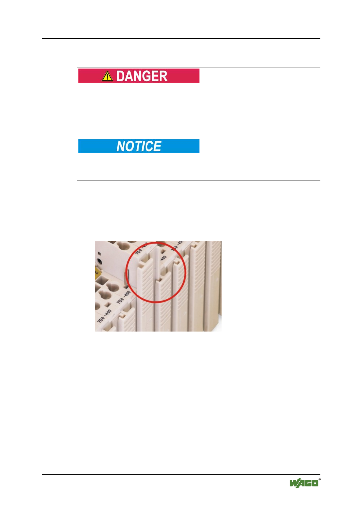
Pos: 60.4 /Serie 750 (WAGO-I/O-SYSTEM)/ Wi c ht i g e Er l ä ut erungen/Si c herheits- und sonstige Hinweise/Achtung/Achtung: An einanderrei hen von B usklemmen nur bei off ener Nut! @ 6\mod_1256193351448_21.d oc @ 43417 @ @ 1
Assemble the I/O modules in rows only if the grooves are open!
Please take into consideration that some I/O modules have no or only a few power
jumper contacts. The design of some modules does not allow them to be
physically assembled in rows, as the grooves for the male contacts are closed at
the top.
Pos: 60.5 /Serie 750 (WAGO-I/O-SYSTEM)/ Wi c ht i g e Er l ä ut erungen/Si c herheits- und sonstige Hi n w ei s e/ H in weis/Hin w ei s : Bu s a bs c hluss nicht ver g essen! @ 6\mod_1256194225557_21.doc @ 43432 @ @ 1
Don't forget the end module!
Always plug an end module 750-600 onto the end of the fieldbus node! You must
always use an end module at all fieldbus nodes with the WAGO I/O System 750
fieldbus couplers/controllers to guarantee proper data transfer.
Pos: 60.6 /Doku mentatio n all g emein/Gli e der ungsele m en te/---Seit enwechsel --- @ 3\mod_12211080450 78_0.doc @ 21810 @ @ 1
Manual
Version 1.1.0
Page 27
WAGO-I/O-SYSTEM 750 Mounting 27
750-585 2AO 0-20mA Ex i
Pos: 60.7 /Serie 750 (WAGO-I/O-SYSTEM)/M ontieren/ Ger äte einfüge n und entfer ne n - Ü berschrif t 2 @ 3\mod_1231768483250_21.doc @ 25950 @ 2 @ 1
4.2 Inserting and Removing Devices
Pos: 60.8 /S erie 750 (WAGO-I/O-SYSTEM ) / Wi c htige Erläut erungen/Si c h erheits- un d sonstige Hinweis e/Gefahr/G efahr: Vors icht bei d er Unterbr echung vo n FE! @ 6\mod_1256193919214_21.doc @ 43423 @ @ 1
Use caution when interrupting the PE!
Make sure that people or equipment are not placed at risk when removing an I/O
module and the associated PE interruption. To prevent interruptions, provide ring
feeding of the ground conductor, see section "Grounding/Ground Conductor" in
manual "System Description WAGO-I/O-SYSTEM 750".
Pos: 60.9 /Al le Serie n (Allgemei ne Module) /Wichtig e Erläuteru ngen/Sich erheits- u nd so nst ig e Hinweis e/ Achtung/A ch tung: Arbei t en a n Geräten nur s pa n nu ng sfrei durch f ü hr e n! @ 6\mod_1256193963573_21.doc @ 43426 @ @ 1
Perform work on devices only if the system is de-energized!
Working on devices when the system is energized can damage the devices.
Therefore, turn off the power supply before working on the devices.
Pos: 60.10 / Serie 750 ( WAGO-I/O-SY STEM)/Mo nt i eren/Buskl emme einfüg en @ 3\mod_1231769726703_21.doc @ 25989 @ 3 @ 1
4.2.1 Inserting I/O Module
1. Position the I/O module so that the tongue and groove joints to the fieldbus
coupler/controller or to the previous or possibly subsequent I/O module are
engaged.
Figure 8: Insert I/O module
2. Press the I/O module into the assembly until the I/O module snaps into the
carrier rail.
Manual
Version 1.1.0
Page 28

28 Mounting WAGO-I/O-SYSTEM 750
750-585 2AO 0-20mA Ex i
Figure 9: Snap the I/O mo dule into place
With the I/O module snapped in place, the electrical connections for the data
contacts and power contacts (if any) to the fieldbus coupler/controller or to the
previous or possibly subsequent I/O module are established.
Pos: 60.11 / Serie 750 ( WAGO-I/O-SY STEM)/Mo nt i eren/Buskl emme entfer nen @ 4\mod_1239169375203_21.doc @ 30334 @ 3 @ 1
4.2.2 Removing the I/O Module
Pos: 61 /Dokum e nt a ti o n al l g e mein/Glie der ungselem en te/---Seiten wechsel--- @ 3\mod_1221108045078_0.doc @ 21810 @ @ 1
1. Remove the I/O module from the assembly by pulling the release tab.
Figure 10: Removing the I/O modul e
Electrical connections for data or power contacts are disconnected when removing
the I/O module.
Manual
Version 1.1.0
Page 29
WAGO-I/O-SYSTEM 750 Connect Devices 29
750-585 2AO 0-20mA Ex i
Pos: 62 /All e Serien ( Allgemeine Module)/Ü ber s chriften für al l e S er i en /Anschließ enGeräte a nschließ en - Üb er sc hrift 1 @ 3\mod_1234172889468_21.doc @ 27460 @ 1 @ 1
5 Connect Devices
Pos: 63 /Ser ie 750 ( WAGO-I/O-SYST EM)/Anschl ießen/Lei ter an CAG E CLAMP anschließe n - Überschri ft 2 und T ext @ 3\ mod_1225448660171_21.doc @ 24928 @ 2 @ 1
5.1 Connecting a Conductor to the CAGE CLAMP®
The WAGO CAGE CLAMP® connection is appropriate for solid, stranded and
finely stranded conductors.
Only connect one conductor to each CAGE CLAMP® connection!
Only one conductor may be connected to each CAGE CLAMP® connection.
Do not connect more than one conductor at one single connection!
If more than one conductor must be routed to one connection, these must be
connected in an up-circuit wiring assembly, for example using WAGO feedthrough terminals.
Exception:
If it is unavoidable to jointly connect 2 conductors, then you must use a ferrule to
join the wires together. The following ferrules can be used:
Length 8 mm
Nominal cross section
WAGO Product 216-103 or products with comparable properties.
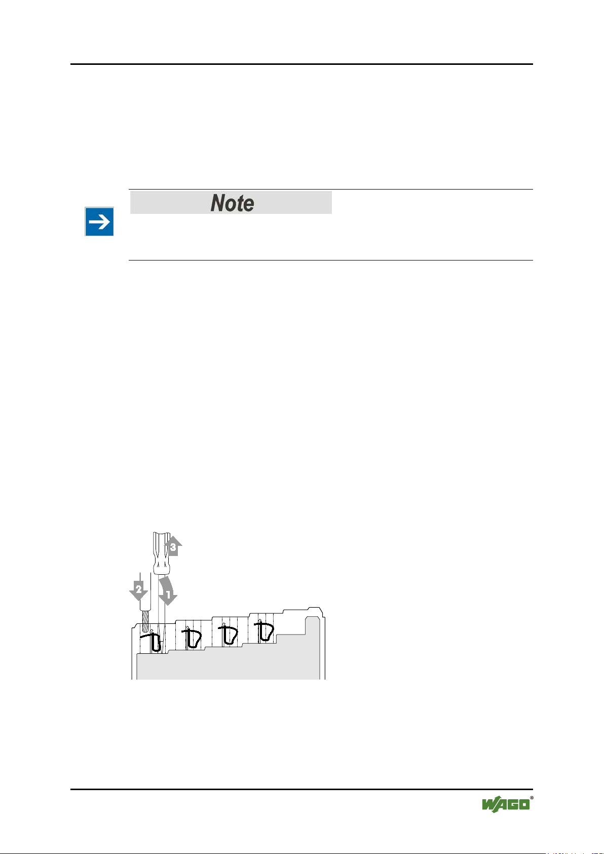
1. To open the CAGE CLAMP® insert the actuating tool into the opening
above the connection.
1 mm2 for 2 conductors with 0.5 mm2 each
max.
Pos: 64 /Dokum e nt a ti o n al l g e mein/Glie der ungselem en te/---Seiten wechsel--- @ 3\mod_1221108045078_0.doc @ 21810 @ @ 1
2. Insert the conductor into the corresponding connection opening.
3. To close the CAGE CLAMP® simply remove the tool - the conductor is
then clamped firmly in place.
Figure 11: Connecting a conductor to a CAGE CLAMP
®
Manual
Version 1.1.0
Page 30

30 Connect Devices WAGO-I/O-SYSTEM 750
750-585 2AO 0-20mA Ex i
Pos: 65 /All e Serien ( Allgemeine Module)/Ü berschrift en für al le Serien/A nschließ enAnschlus sbeispiel - Ü berschrif t 2 @ 4\mod_1242621672468_21.doc @ 33293 @ 2 @ 1
5.2 Connection Example
Pos: 66 /Ser ie 750 ( WAGO-I/O-SYST EM)/Anschl ießen/An schlussbeis piele/A nalogausga ngsklemm en/Anschlus sbeispiele 750-0585 @ 5\ mod_1247206486748_21.doc @ 37 110 @ @ 1
Figure 12: Conne cting diagram
Pos: 67 /Dokum e nt a ti o n al l g e mein/Glie der ungselem en te/---Seiten wechsel--- @ 3\mod_1221108045078_0.doc @ 21810 @ @ 1
Manual
Version 1.1.0
Page 31

WAGO-I/O-SYSTEM 750 Process Image 31
Table 12: Process Image
binary
Output value
4
'0000.0000.0000.0000'
0x0000 0 0x00
6
'0001.0000.0000.0000'
0x1000
4096
0x00
8
'0010.0000.0000.0000'
0x2000
8192
0x00
10
'0011.0000.0000.0000'
0x3000
12288
0x00
12
'0100.0000.0000.0000'
0x4000
16384
0x00
14
'0101.0000.0000.0000'
0x5000
20480
0x00
16
'0110.0000.0000.0000'
0x6000
24576
0x00
18
'0111.0000.0000.0000'
0x7000
28672
0x00
20
'0111.1111.1111.1111'
0x7FFF
32767
0x00
750-585 2AO 0-20mA Ex i
Pos: 68 /All e Serien ( Allgemeine Module)/Ü berschrift en für al le Serien/P rozessab bild - Übers c hrift 1 @ 4\mod_1240983067828_21.doc @ 31942 @ 1 @ 1
6 Process Image
Pos: 69 /Ser ie 750 ( WAGO-I/O-SYST EM)/Prozessabbild Klemmenbus/Hinweis: Prozessabbildmapping abhängig von FBK/PFC, ohne Status-/Controlbyte @ 6\mod_1256126797251_2 1.doc @ 43340 @ @ 1
Mapping of process data in the process image of fieldbus systems
The representation of the process data of some I/O modules or their variations in
the process image depends on the fieldbus coupler/controller used. Please take
this information from the section "Fieldbus Specific Design of the Process Data"
included in the description concerning the process image of the corresponding
coupler/controller.
Pos: 70 /Ser ie 750 ( WAGO-I/O-SYST EM)/Proz essabbild Kl emmenbus /Hinweis: Statusbyt e-Auswertu ng nicht möglich @ 6 \mod_1256127653548_21.doc @ 43347 @ @ 1
No Status Byte to evaluate!
Some fieldbus systems can process the status information of process values using
by means of a status byte.
As the returned status byte of this I/O module is always zero, it will not be parsed.
Pos: 71 /Ser ie 750 ( WAGO-I/O-SYST EM)/Proz essabbild Kl emmenbus /Analoga usgangskle mmen/Proz essabbild 7 50- 0585 @ 5\ mod_1246000790937_21.doc @ 36176 @ @ 1
The analog output module 750-585 transmits 16-bit measured values and 8
optional status bits per channel.
The digitalized output value is transmitted in a data word (16 bits) as output byte
0 (low) and output byte 1 (high) via the process image of the
fielbuscoupler/controller.
The output current ranging from 0 mA to 20 mA is scaled on the numerical values
ranging from 0x0000 to 0x7FFF.
This value is represented with a 12 bit resolution on bit B3 ... B14. The three least
significant bits (B0 ... B2) are not parsed.
Output current
4 mA ... 20 mA
Numercial value
hex. dec.
Status-
byte
hex.
Pos: 72 /Dokum e nt a ti o n al l g e mein/Glie der ungselem en te/---Seiten wechsel--- @ 3\mod_1221108045078_0.doc @ 21810 @ @ 1
Manual
Version 1.1.0
Page 32

32 Use in Hazardous Environments WAGO-I/O-SYSTEM 750
750-585 2AO 0-20mA Ex i
Pos: 73.1 /Al le Serie n (Allgemei ne Module) /Einsatz in Ex-Berei c h e n/ Ei nsatz in expl osi onsgefä hr d eten Bereic he n - Ü berschrif t 1 @ 3\mod_1224075191281_21.doc @ 24084 @ 1 @ 1
7 Use in Hazardou s E nvironments
Pos: 73.2 /Serie 750 (WAGO-I/O-SYSTEM)/Eins atz in Ex-B ereichen/Ei nsatzber eich Serie 750 @ 3\mod_1234272230203_21.doc @ 27500 @ @ 1
The WAGO-I/O-SYSTEM 750 (electrical equipment) is designed for use in
Zone 2 hazardous areas.
The following sections include both the general identification of components
(devices) and the installation regulations to be observed. The individual
subsections of the "Installation Regulations" section must be taken into account if
the I/O module has the required approval or is subject to the range of application
of the ATEX directive.
Pos: 73.3 /Dokumentation allgemein/Gliederungselemente/ ---Seitenwechs el--- @ 3\mod_1221108045078_0.doc @ 21810 @ @ 1
Manual
Version 1.1.0
Page 33

WAGO-I/O-SYSTEM 750 Use in Hazardous Environments 33
Table 13: Description of marking example for ATEX and IEC Ex approved I/O modules according
to CENELEC and IEC
Printing on Text
Description
DEMKO 08 ATEX 142851 X
IECEx PTB 07.0064X
Approval body and/or number of the examination
certificate
I M2 / II 3 GD
Explosion protection group and Unit category
Ex nA
Type of ignition and extended identification
IIC
Explosion protection group
T4
Temperature class
750-585 2AO 0-20mA Ex i
Pos: 73.4 /Serie 750 (WAGO-I/O-SYSTEM)/Eins atz in Ex-B ereichen/B eispielha fter Aufba u der Kennz eichnung - Ü berschrif t 2 @ 3\mod_1224157499140_21.doc @ 24182 @ 2 @ 1
7.1 Marking Configuration Examples
Pos: 73.5 /Serie 750 (WAGO-I/O-SYSTEM)/Eins atz in Ex-B ereichen/K ennzeichn ung für Eur opa gemäß CENELEC und IEC - Ü berschrift 3 @ 3\mod_1224157620203_21.doc @ 24185 @ 3 @ 1
7.1.1 Marking for Europe according to CENELEC and IEC
Pos: 73.6 /S erie 750 (WAGO-I/O-SYSTEM)/Eins atz in Ex-B ereichen/B eispielbe druckung d er ATEX- un d IE C- Ex-zugelasse nen Buskle mmen gemäß CENELEC und IEC @ 7 \mod_1274340031573 _21.doc @ 56687 @ @ 1
Pos: 73.7 /Dokumentation allgemein/Gliederungselemente/---Seitenwechsel--- @ 3\mod_1221108045078_0.do c @ 21810 @ @ 1
Figure 13: Side marking example for ATEX and IEC Ex approved I/O modules according to
CENELEC and IEC
Figure 14: Printing Text de ta il – Marking example for ATEX and IEC Ex approved I/O modules
according to CENELEC and IEC
Manual
Version 1.1.0
Page 34

34 Use in Hazardous Environments WAGO-I/O-SYSTEM 750
750-585 2AO 0-20mA Ex i
Pos: 73.8 /Serie 750 (WAGO-I/O-SYSTEM)/Eins atz in Ex-Ber eichen/Bei spielbedr uckung der Ex-i- und IEC-Ex-i-zugelasse nen Buskle mmen gem äß CENELEC und IEC @ 7\mod_1274338578856_21.doc @ 56679 @ @ 1
Figure 15: Side marking example for Ex i and IEC Ex i approved I/O modules according to
CENELEC and IEC
Figure 16: Text deta il – Marking exa mpl e for Ex i and IEC Ex i ap proved I/ O modules according
to CENELEC and IEC
Manual
Version 1.1.0
Page 35

WAGO-I/O-SYSTEM 750 Use in Hazardous Environments 35
Table 14: Description of marking example for Ex i and IEC Ex i approved I/O modules according to
CENELEC and IEC
Inscription text
Description
TÜV 07 ATEX 554086 X
TUN 09.0001X
Approving authority or
certificate numbers
Dust
II
Device group: All except mining
3(1)D
Device category: Zone 22 device (Zone 20 subunit)
Ex
Explosion protection mark
tD
Protection by enclosure
[iaD]
Approved in accordance with "Dust intrinsic safety"
standard
A22
Surface temperature determined according to
Procedure A, use in Zone 22
IP6X
Dust-tight (totally protected against dust)
T 135°C
Max. surface temp. of the enclosure (no dust bin)
Mining
I
Device group: Mining
(M2)
Device category: High degree of safety
[Ex ia]
Explosion protection: Mark with category of type of
errors occur
I
Device group: Mining
Gases
II
Device group: All except mining
3(1)G
Device category: Zone 2 device (Zone 0 subunit)
Ex
Explosion protection mark
nA
Type of protection: Non-sparking operating
equipment
[ia]
Category of type of protection intrinsic safety: Even
safe when two errors occur
IIC
Explosion Group
T4
Temperature class: Max. surface temperature 135°C
750-585 2AO 0-20mA Ex i
Pos: 73.9 /Dokumentation allgemein/Gliederungselemente/---Seitenwechsel--- @ 3\mod_1221108045078_0.do c @ 21810 @ @ 1
protection intrinsic safety: Even safe when two
Manual
Version 1.1.0
Page 36

36 Use in Hazardous Environments WAGO-I/O-SYSTEM 750
Table 15: Description of marking example for I/O modules according to NEC 500
Printing on Text
Description
CL 1
Explosion protection group (condition of use
category)
DIV 2
Area of application (zone)
Grp. ABCD
Explosion group (gas group)
Optemp code T4
Temperature class
750-585 2AO 0-20mA Ex i
Pos: 73.10 / Serie 750 ( WAGO-I/O-SY STEM)/Einsa tz in Ex-Ber eichen/Ken nzeichnung für Ameri ka gemäß N EC 500 - Ü b er sc hrift 3 @ 3\mod_1224158423187_21.do c @ 24 188 @ 3 @ 1
7.1.2 Marking for America according to NEC 500
Pos: 73.11 / Serie 750 ( WAGO-I/O-SY STEM)/Einsa tz in Ex-Ber eichen/B eispielbedr uckung g emäß NEC 5 00 @ 7\mod_1274339607920_21.doc @ 56683 @ @ 1
Figure 17: Side marking example for I/O modules according to NEC 500
Pos: 73.12 /Dokumentation a llgemein/Gliederungselemente/---Seitenwechsel--- @ 3\mod_1221108045078_0.doc @ 21810 @ @ 1
Figure 18: Text de ta il – Marking example for I/O modules according to NEC 500
Manual
Version 1.1.0
Page 37

WAGO-I/O-SYSTEM 750 Use in Hazardous Environments 37
Table 16: VDE Installation Regulations in German y
DIN VDE 0100
Installation in power plants with rated voltages up to 1000 V
DIN VDE 0101
Installation in power plants with rated voltages above 1 kV
DIN VDE 0800
Installation and operation in telecommunication plants including
information processing equipment
DIN VDE 0185
lightning protection systems
Table 17: Installation Regulations in USA and Canada
NFPA 70
National Electrical Code Art. 500 Hazardous Locations
ANSI/ISA-RP 12.6-1987
Recommended Practice
C22.1
Canadian Electrical Code
750-585 2AO 0-20mA Ex i
Pos: 73.13 / Alle Seri en (Allgem eine Modul e)/Einsatz in Ex-Berei chen/Err ichtungsb estimmung en @ 3\mod_1232453624234_21.doc @ 26370 @ 2 @ 1
7.2 Installation Regulations
Pos: 73.14 / Alle Seri en (Allgem eine Modul e)/Einsatz in Ex-Berei chen/Err ichtungsb estimmung en Einleit ung @ 3\mod_1232453837234_21.doc @ 26374 @ @ 1
In the Federal Republic of Germany, various national regulations for the
installation in explosive areas must be taken into consideration. The basis for this
forms the working reliability regulation, which is the national conversion of the
European guideline 99/92/E6. They are complemented by the installation
regulation EN 60079-14. The following are excerpts from additional VDE
regulations:
The USA and Canada have their own regulations. The following are excerpts
from these regulations:
Pos: 73.15 /D okument ation allge mein/Gli ederungsel emente/------Leerz eile------ @ 3\mod_1224662755687_0.doc @ 24460 @ @ 1
Pos: 73.16 /D okument ation allge mein/Gli ederungsel emente/------Leerz eile------ @ 3\mod_1224662755687_0.doc @ 24460 @ @ 1
Pos: 73.17 /D okument ation allge mein/Gli ederungsel emente/------Leerz eile------ @ 3\mod_1224662755687_0.doc @ 24460 @ @ 1
Pos: 73.18 / Serie 750 ( WAGO-I/O-SY STEM)/Einsa tz in Ex-Ber eichen/Ac htung: Err ichtungsb estimmung en Serie 7 50 beachte n @ 3\mod_1224158893890_21.do c @ 24191 @ @ 1
Notice the following points
When using the WAGO-I/O SYSTEM 750 (electrical operation) with Ex
approval, the following points are mandatory:
Pos: 73.19 /Dokumentation allgemein/Gl iederungselemente /---Seitenwec hsel--- @ 3\mod_1221108045078_0.doc @ 21810 @ @ 1
Manual
Version 1.1.0
Page 38

38 Use in Hazardous Environments WAGO-I/O-SYSTEM 750
750-585 2AO 0-20mA Ex i
Pos: 73.20 / Serie 750 ( WAGO-I/O-SY STEM)/Einsa tz in Ex-Ber ei c hen/Beso n der e Bedingung e n f ür d en sic h er en ATEX- und IEC-Ex-Betrieb g em. DEMK O 08 ATEX 14 28 5 1X & IECEx @ 7\mod_1274277358920_21.doc @ 56642 @ 3 @ 1
7.2.1 Special Conditions for Saf e Oper a t ion of t he ATEX and IEC Ex (acc. DEMKO 08 ATEX 142851X and IECEx PTB 07.0064)
The fieldbus-independent I/O modules of the WAGO-I/O-SYSTEM 750-.../...-...
must be installed in an environment with degree of pollution 2 or better. In the
final application, the I/O modules must be mounted in an enclosure with IP 54
degree of protection at a minimum with the following exceptions:
- I/O modules 750-440, 750-609 and 750-611 must be installed in an IP 64
minimum enclosure.
- I/O module 750-540 must be installed in an IP 64 minimum enclosure for
230 V AC applications.
- I/O module 750-440 may be used up to max. 120 V AC.
When used in the presence of combustible dust, all devices and the enclosure shall
be fully tested and assessed in compliance with the requirements of IEC 612410:2004 and IEC 61241-1:2004.
When used in mining applications the equipment shall be installed in a suitable
enclosure according to EN 60079-0:2006 and EN 60079-1:2007.
Pos: 73.21 /D okument ation allge mein/Gli ederungsel emente/---Seit enwechsel--- @ 3\mod_1221108045078_0.doc @ 21810 @ @ 1
I/O modules fieldbus plugs or fuses may only be installed, added, removed or
replaced when the system and field supply is switched off or the area exhibits no
explosive atmosphere.
DIP switches, coding switches and potentiometers that are connected to the I/O
module may only be operated if an explosive atmosphere can be ruled out.
I/O module 750-642 may only be used in conjunction with antenna 758-910 with
a max. cable length of 2.5 m.
To exceed the rated voltage no more than 40%, the supply connections must have
transient protection.
The permissible ambient temperature range is 0 °C to +55 °C.
Manual
Version 1.1.0
Page 39

WAGO-I/O-SYSTEM 750 Use in Hazardous Environments 39
750-585 2AO 0-20mA Ex i
Pos: 73.22 /Ser ie 750 (W AGO-I/O-SYST EM)/Einsatz i n Ex-Bereic he n/Besonder e Bedingung en für den sich er en Ex-Betri eb gem. ATEX-Z ertifikat T ÜV 07 AT EX 554086 X @ 12\mod_1340262566733_21.doc @ 98182 @ 3 @ 1
7.2.2 Special conditions for safe use (ATEX Certificate TÜV 07 ATEX 554086 X)
1. For use as Gc- or Dc-apparatus (in zone 2 or 22) the field bus independent
I/O modules WAGO-I/O-SYSTEM 750-*** shall be erected in an enclosure
that fulfils the requirements of the applicable standards (see the marking)
EN 60079-0, EN 60079-11, EN 60079-15, EN 61241-0 and EN 61241-1.
For use as group I, electrical apparatus M2, the apparatus shall be erected in
an enclosure that ensures a sufficient protection according to EN 60079-0
and EN 60079-1 and the degree of protection IP64. The compliance of these
requirements and the correct installation into an enclosure or a control
cabinet of the devices shall be certified by an ExNB.
2. If the interface circuits are operated without the field bus coupler station
type 750-3../…-… (DEMKO 08 ATEX 142851 X), measures must be taken
outside of the device so that the rating voltage is not being exceeded of
more than 40% because of transient disturbances.
3. DIP-switches, binary-switches and potentiometers, connected to the module
may only be actuated when explosive atmosphere can be excluded.
Pos: 73.23 /D okument ation allge mein/Gli ederungsel emente/---Seit enwechsel--- @ 3\mod_1221108045078_0.doc @ 21810 @ @ 1
4. The connecting and disconnecting of the non-intrinsically safe circuits is
only permitted during installation, for maintenance or for repair purposes.
The temporal coincidence of explosion hazardous atmosphere and
installation, maintenance resp. repair purposes shall be excluded. This is
although and in particular valid for the interfaces “CF-Card”, “USB”,
“Fieldbus connection“, “Configuration and programming interface“,
“antenna socket“, “D-Sub“ and the “Ethernet interface“. These interfaces
are not energy limited or intrinsically safe circuits. An operating of those
circuits is in the behalf of the operator.
5. For the types 750-606, 750-625/000-001, 750-487/003-000, 750-484 and
750-633 the following shall be considered: The interface circuits shall be
limited to overvoltage category I/II/III (non mains/mains circuits) as defined
in EN 60664-1.
6. For the type 750-601 the following shall be considered: Do not remove or
replace the fuse when the apparatus is energized.
7. The ambient temperature range is: 0°C ≤ Ta ≤ +55°C (for extended details
please note certificate).
Manual
Version 1.1.0
Page 40

40 Use in Hazardous Environments WAGO-I/O-SYSTEM 750
750-585 2AO 0-20mA Ex i
Pos: 73.24 / Alle Seri en (Allgem eine Modul e)/Einsatz in Ex-Bereichen/Hinweisanhang - In der Nähe des Gerätes sin d di e fol g enden Warn hi n w ei s e anzubring e n: @ 11\mod_1326966656062_21.doc @ 86612 @ @ 1
8. The following warnings shall be placed nearby the unit:
Pos: 73.25 / Alle Seri en (Allgem eine Modul e)/Wichti ge Erläuter ungen/Sic herheits- und sonstige Hin weise/War nung/War nu ng : Si ch erung nich t un ter S p a nn u ng herausne h m en o der wechsel n! @ 11\ mod_1326959227633_21.doc @ 86570 @ @ 1
Do not remove or replace fuse when energized!
If the module is energized do not remove or replace the fuse.
Pos: 73.26 / Alle Seri en (Allgem eine Modul e)/Wichti ge Erläuter ungen/Sic herheits- und sonstig e Hinweise /Warnung /Warnung: N icht unt er Spannung trennen! @ 11\mod_1326963689811_21.doc @ 86573 @ @ 1
Do not separate when energized!
Do not separate the module when energized!
Pos: 73.27 / Alle Seri en (Allgem eine Modul e)/Wichti ge Erläuter ungen/Sic herheits- und sonstig e Hinweise /Warnung /Warnung: N ur in ein em nicht e xplosionsg efährdete n Bereich t rennen! @ 11\mod_1326964057288_21 .doc @ 86576 @ @ 1
Separate only in a non-hazardous area!
Separate the module only in a non-hazardous area!
Pos: 73.28 /D okument ation allge mein/Gli ederungsel emente/---Seit enwechsel--- @ 3\mod_1221108045078_0.doc @ 21810 @ @ 1
Manual
Version 1.1.0
Page 41

WAGO-I/O-SYSTEM 750 Use in Hazardous Environments 41
750-585 2AO 0-20mA Ex i
Pos: 73.29 / Serie 750 ( WAGO-I/O-SY STEM)/Einsa tz in Ex-Ber ei c hen/Beso n der e Bedingung e n f ür d en sic h er en Ex-Betrieb gem. IEC-Ex-Zertifikat TUN 09.0001 X @ 12\mod_1340260483271_21.doc @ 98174 @ 3 @ 1
7.2.3 Special conditions for s af e use (I E C-Ex Cert ificate TUN
09.0001 X)
1. For use as Dc- or Gc-apparatus (in zone 2 or 22) the fieldbus independent
I/O modules WAGO-I/O-SYSTEM 750-*** shall be erected in an enclosure
that fulfils the requirements of the applicable standards (see the marking)
IEC 60079-0, IEC 60079-11, IEC 60079-15, IEC 61241-0 and IEC 61241-1.
For use as group I, electrical apparatus M2, the apparatus shall be erected in
an enclosure that ensures a sufficient protection according to IEC 60079-0
and IEC 60079-1 and the degree of protection IP64. The compliance of
these requirements and the correct installation into an enclosure or a control
cabinet of the devices shall be certified by an ExCB.
2. Measures have to be taken outside of the device that the rating voltage is not
being exceeded of more than 40% because of transient disturbances.
3. DIP-switches, binary-switches and potentiometers, connected to the module
may only be actuated when explosive atmosphere can be excluded.
Pos: 73.30 /D okument ation allge mein/Gli ederungsel emente/---Seit enwechsel--- @ 3\mod_1221108045078_0.doc @ 21810 @ @ 1
4. The connecting and disconnecting of the non-intrinsically safe circuits is
only permitted during installation, for maintenance or for repair purposes.
The temporal coincidence of explosion hazardous atmosphere and
installation, maintenance resp. repair purposes shall be excluded. This is
although and in particular valid for the interfaces “CF-Card”, “USB”,
“Fieldbus connection“, “Configuration and programming interface“,
“antenna socket“, “D-Sub“ and the “Ethernet interface“. These interfaces
are not energy limited or intrinsically safe circuits. An operating of those
circuits is in the behalf of the operator.
5. For the types 750-606, 750-625/000-001, 750-487/003-000, 750-484 and
750-633 the following shall be considered: The interface circuits shall be
limited to overvoltage category I/II/III (non mains/mains circuits) as defined
in IEC 60664-1.
6. For the type 750-601 the following shall be considered: Do not remove or
replace the fuse when the apparatus is energized.
7. The ambient temperature range is: 0°C ≤ Ta ≤ +55°C (For extensions please
see the certificate).
Manual
Version 1.1.0
Page 42

42 Use in Hazardous Environments WAGO-I/O-SYSTEM 750
750-585 2AO 0-20mA Ex i
Pos: 73.31 / Alle Seri en (Allgem eine Modul e)/Einsatz in Ex-Bereichen/Hinweisanhang - In der Nähe des Gerätes sin d di e fol g enden Warn hi n w ei s e anzubring e n: @ 11\mod_1326966656062_21.doc @ 86612 @ @ 1
8. The following warnings shall be placed nearby the unit:
Pos: 73.32 / Alle Seri en (Allgem eine Modul e)/Wichti ge Erläuter ungen/Sic herheits- und sonstige Hin weise/War nung/War nu ng : Si ch erung nich t un ter S p a nn u ng herausne h m en o der wechsel n! @ 11\ mod_1326959227633_21.doc @ 86570 @ @ 1
Do not remove or replace fuse when energized!
If the module is energized do not remove or replace the fuse.
Pos: 73.33 / Alle Seri en (Allgem eine Modul e)/Wichti ge Erläuter ungen/Sic herheits- und sonstig e Hinweise /Warnung /Warnung: N icht unt er Spannung trennen! @ 11\mod_1326963689811_21.doc @ 86573 @ @ 1
Do not separate when energized!
Do not separate the module when energized!
Pos: 73.34 / Alle Seri en (Allgem eine Modul e)/Wichti ge Erläuter ungen/Sic herheits- und sonstig e Hinweise /Warnung /Warnung: N ur in ein em nicht e xplosionsg efährdete n Bereich t rennen! @ 11\mod_1326964057288_21.doc @ 86576 @ @ 1
Separate only in a non-hazardous area!
Separate the module only in a non-hazardous area!
Pos: 73.35 /Dokumentation allgemein/Gl iederungselemente /---Seitenwec hsel--- @ 3\mod_1221108045078_0.doc @ 21810 @ @ 1
Manual
Version 1.1.0
Page 43
WAGO-I/O-SYSTEM 750 Use in Hazardous Environments 43
750-585 2AO 0-20mA Ex i
Pos: 73.36 / Serie 750 ( WAGO-I/O-SY STEM)/Einsa tz in Ex-Ber ei c hen/Erric ht ungsbesti mmungen AN SI IS A 12 .1 2. 01 @ 12\mod_1341211262574_21.doc @ 98730 @ 3 @ 1
7.2.4 ANSI/ISA 12.12.01
This equipment is suitable for use in Class I, Division 2, Groups A, B, C, D or
non-hazardous locations only.
This equipment is to be fitted within tool-secured enclosures only.
Explosion hazard!
Explosion hazard - substitution of components may impair suitability for Class I,
Div. 2.
Disconnect device when power is off and only in a non-hazardous area!
Do not disconnect equipment unless power has been switched off or the area is
known to be non-hazardous near each operator accessible connector and fuse
holder." When a fuse is provided, the following information shall be provided: “A
switch suitable for the location where the equipment is installed shall be provided
to remove the power from the fuse.”
For devices with Ethernet connectors:
”Only for use in LAN, not for connection to telecommunication circuits”.
Use only with antenna module 758-910!
Use Module 750-642 only with antenna module 758-910.
For Couplers/Controllers and Economy bus modules only: "The configuration
Interface Service connector is for temporary connection only. Do not connect or
disconnect unless the area is known to be nonhazardous. Connection or
disconnection in an explosive atmosphere could result in an explosion.
Devices containing fuses must not be fitted into circuits subject to over loads!
Devices containing fuses must not be fitted into circuits subject to over loads, e.g.
motor circuits!
Manual
Version 1.1.0
Page 44
44 Use in Hazardous Environments WAGO-I/O-SYSTEM 750
750-585 2AO 0-20mA Ex i
Do not connect or disconnect SD-Card unless the area known to be free of
ignitable concentrations of flammable gases or vapors!
Do not connect or disconnect SD-Card while circuit is live unless the area is
known to be free of ignitable concentrations of flammable gases or vapors.
Pos: 73.37 /D okument ation allge mein/Gli ederungsel emente/------Leerz eile------ @ 3\mod_1224662755687_0.doc @ 24460 @ @ 1
Pos: 73.38 /D okument ation allge mein/Gli ederungsel emente/------Leerz eile------ @ 3\mod_1224662755687_0.doc @ 2446 0 @ @ 1
Pos: 73.39 /D okument ation allge mein/Gli ederungsel emente/------Leerz eile------ @ 3\mod_1224662755687_0.doc @ 24460 @ @ 1
Pos: 73.40 / Serie 750 ( WAGO-I/O-SY STEM)/Einsa tz in Ex-Ber eichen/In formation: Zertifizi erungsnac hweis @ 7\ mod_1274279547729_21.doc @ 56649 @ @ 1
Additional Information
Proof of certification is available on request. Also take note of the information
given on the module technical information sheet. The Instruction Manual,
containing these special conditions for safe use, must be readily available to the
user.
=== Ende der Liste für Textmar ke Inhalt_ mitte ===
Manual
Version 1.1.0
Page 45

WAGO-I/O-SYSTEM 750 List of Figures 45
750-585 2AO 0-20mA Ex i
Pos: 75 /Dokum e nt a ti o n al l g e mein/Verz ei c hni s s e/Abbildu ngsverzei c hnis - ohne Gliederung - und Verzeichnis @ 3\ mod_1219222916765_21.doc @ 21080 @ @ 1
List of Figures
Figure 1: Supply Principle Ex i ............................................................................. 14
Figure 2: View ....................................................................................................... 16
Figure 3: Data contacts .......................................................................................... 17
Figure 4: Power jumper contacts ........................................................................... 18
Fig. 5: Connections ................................................................................................ 19
Figure 6: Display elements .................................................................................... 20
Fig. 7: Schematic diagram ..................................................................................... 21
Figure 8: Insert I/O module ................................................................................... 27
Figure 9: Snap the I/O module into place .............................................................. 28
Figure 10: Removing the I/O module .................................................................... 28
Figure 11: Connecting a conductor to a CAGE CLAMP® .................................... 29
Figure 12: Connecting diagram ............................................................................. 30
Figure 13: Side marking example for ATEX and IEC Ex approved I/O modules
according to CENELEC and IEC ................................................................ 33
Figure 14: Printing Text detail – Marking example for ATEX and IEC Ex
approved I/O modules according to CENELEC and IEC ............................ 33
Figure 15: Side marking example for Ex i and IEC Ex i approved I/O modules
according to CENELEC and IEC ................................................................ 34
Figure 16: Text detail – Marking example for Ex i and IEC Ex i approved I/O
modules according to CENELEC and IEC .................................................. 34
Figure 17: Side marking example for I/O modules according to NEC 500 .......... 36
Figure 18: Text detail – Marking example for I/O modules according to NEC 500
...................................................................................................................... 36
Pos: 76 /Dokum e nt a ti o n al l g e mein/Glie der ungselem en te/---Seiten wechsel--- @ 3\mod_1221108045078_0.doc @ 21810 @ @ 1
Manual
Version 1.1.0
Page 46

46 List of Tables WAGO-I/O-SYSTEM 750
750-585 2AO 0-20mA Ex i
Pos: 77 /Dokum e nta tion allge mei n/Verzeic hnisse/Ta bel l enverzei ch nis - ohne Glie derung - und Verzeichni s @ 3\mod_1219222958703_21.doc @ 21084 @ @ 1
List of Tables
Table 1: Number Notation ....................................................................................... 8
Table 2: Font Conventions ...................................................................................... 8
Table 3: Caption acc. to figure “View“ ................................................................. 16
Table 4: Power jumper contacts ............................................................................ 18
Table 5: Connections ............................................................................................. 19
Table 6: Display elements ..................................................................................... 20
Table 7: Technical data device .............................................................................. 22
Table 8: Technical data supply .............................................................................. 22
Table 9: Technical data communication ............................................................... 22
Table 10: Technical data inputs ............................................................................. 22
Table 11: Technical data Explosion Protection ..................................................... 23
Table 12: Process Image ........................................................................................ 31
Table 13: Description of marking example for ATEX and IEC Ex approved I/O
modules according to CENELEC and IEC .................................................. 33
Table 14: Description of marking example for Ex i and IEC Ex i approved I/O
modules according to CENELEC and IEC .................................................. 35
Table 15: Description of marking example for I/O modules according to NEC 500
...................................................................................................................... 36
Table 16: VDE Installation Regulations in Germany ........................................... 37
Table 17: Installation Regulations in USA and Canada ........................................ 37
Manual
Version 1.1.0
Page 47

WAGO-I/O-SYSTEM 750 List of Tables 47
750-585 2AO 0-20mA Ex i
=== Ende der Liste für Textmar ke Verzeich nis_hinte n ===
Manual
Version 1.1.0
Page 48

WAGO Kontakttechnik GmbH & Co. KG
Pos: 79 /Dokumentation allgemein/Einband/Einband Handbuch - Rückseite @ 9\ mod_1285229376516_21.doc @ 64944 @ @ 1
Postfach 2880 • D-32385 Minden
Hansastraße 27 • D-32423 Minden
Phone: +49/ 5 71/8 87 – 0
Fax: +49/5 71/8 87 – 1 69
E-Mail: info@wago.com
Internet: http://www.wago.com
=== Ende der Liste für Textmar ke Einband _hinten ===
 Loading...