

Page 1
WAGO-I/O-SYSTEM 750
Manual
750-306
Fieldbus Coupler
Version 2.0.0
DeviceNetTM
125 Kbaud ... 500 Kbaud; digital and analog signals
Page 2

2 WAGO-I/O-SYSTEM 750
750-306 DeviceNet
TM
Fieldbus Coupler
© 2015 by WAGO Kontakttechnik GmbH & Co. KG
All rights reserved.
WAGO Kontakttechnik GmbH & Co. KG
Hansastraße 27
D-32423 Minden
Phone: +49 (0) 571/8 87 – 0
Fax: +49 (0) 571/8 87 – 1 69
E-Mail: info@wago.com
Web: http://www.wago.com
Technical Support
Phone: +49 (0) 571/8 87 – 5 55
Fax: +49 (0) 571/8 87 – 85 55
E-Mail: support@wago.com
Every conceivable measure has been taken to ensure the accuracy and
completeness of this documentation. However, as errors can never be fully
excluded, we always appreciate any information or suggestions for improving the
documentation.
E-Mail: documentation@wago.com
We wish to point out that the software and hardware terms as well as the
trademarks of companies used and/or mentioned in the present manual are
generally protected by trademark or patent.
Manual
Version 2.0.0
Page 3

WAGO-I/O-SYSTEM 750 Table of Contents 3
750-306 DeviceNet
TM
Fieldbus Coupler
Table of Contents
1 Notes about this Documentation ................................................................. 7
1.1 Validity of this Documentation ................................................................. 7
1.2 Copyright ................................................................................................... 7
1.3 Symbols ..................................................................................................... 8
1.4 Number Notation ..................................................................................... 10
1.5 Font Conventions .................................................................................... 10
2 Important Notes ......................................................................................... 11
2.1 Legal Bases ............................................................................................. 11
2.1.1 Subject to Changes ............................................................................. 11
2.1.2 Personnel Qualifications ..................................................................... 11
2.1.3 Use of the WAGO-I/O-SYSTEM 750 in Compliance with Underlying
Provisions ........................................................................................... 11
2.1.4 Technical Condition of Specified Devices ......................................... 12
2.2 Safety Advice (Precautions) .................................................................... 13
3 System Description..................................................................................... 15
3.1 Manufacturing Number ........................................................................... 16
3.2 Component Update .................................................................................. 17
3.3 Storage, Assembly and Transport ........................................................... 17
3.4 Assembly Guidelines/Standards .............................................................. 18
3.5 Power Supply .......................................................................................... 19
3.5.1 Isolation .............................................................................................. 19
3.5.2 System Supply .................................................................................... 20
3.5.2.1 Connection ..................................................................................... 20
3.5.2.2 Dimensioning ................................................................................. 21
3.5.3 Field Supply........................................................................................ 24
3.5.3.1 Connection ..................................................................................... 24
3.5.3.2 Fusing ............................................................................................ 26
3.5.4 Supplementary Power Supply Regulations ........................................ 29
3.5.5 Supply Example.................................................................................. 30
3.5.6 Power Supply Unit ............................................................................. 32
3.6 Grounding ............................................................................................... 33
3.6.1 Grounding the DIN Rail ..................................................................... 33
3.6.1.1 Framework Assembly .................................................................... 33
3.6.1.2 Insulated Assembly ........................................................................ 33
3.6.2 Grounding Function............................................................................ 34
3.7 Shielding ................................................................................................. 35
3.7.1 General ............................................................................................... 35
3.7.2 Bus Cables .......................................................................................... 35
3.7.3 Signal Lines ........................................................................................ 36
3.7.4 WAGO Shield Connecting System .................................................... 36
4 Device Description ..................................................................................... 37
4.1 View ........................................................................................................ 38
4.2 Connectors ............................................................................................... 40
4.2.1 Device Supply .................................................................................... 40
4.2.2 Fieldbus Connection ........................................................................... 41
Manual
Version 2.0.0
Page 4

4 Table of Contents WAGO-I/O-SYSTEM 750
750-306 DeviceNet
TM
Fieldbus Coupler
4.3 Display Elements .................................................................................... 42
4.4 Operating Elements ................................................................................. 43
4.4.1 Service Interface ................................................................................. 43
4.4.2 DIP Switch.......................................................................................... 44
4.4.2.1 Baud Rate Setting .......................................................................... 44
4.4.2.2 Station address ............................................................................... 45
4.5 Technical Data ........................................................................................ 46
4.5.1 Device Data ........................................................................................ 46
4.5.2 System Data ........................................................................................ 46
4.5.3 DeviceNetTM Fieldbus ........................................................................ 46
4.5.4 Supply ................................................................................................. 47
4.5.5 Accessories ......................................................................................... 47
4.5.6 Connection Type ................................................................................ 47
4.5.7 Climatic Environmental Conditions ................................................... 48
4.5.8 Mechanical Strength acc. to IEC 61131-2 .......................................... 48
4.6 Approvals ................................................................................................ 49
4.7 Standards and Guidelines ........................................................................ 51
5 Mounting ..................................................................................................... 52
5.1 Installation Position ................................................................................. 52
5.2 Overall Configuration ............................................................................. 52
5.3 Mounting onto Carrier Rail ..................................................................... 54
5.3.1 Carrier Rail Properties ........................................................................ 54
5.3.2 WAGO DIN Rail ................................................................................ 55
5.4 Spacing .................................................................................................... 55
5.5 Mounting Sequence ................................................................................. 56
5.6 Inserting and Removing Devices ............................................................ 57
5.6.1 Inserting the Fieldbus Coupler/Controller .......................................... 58
5.6.2 Removing the Fieldbus Coupler/Controller ....................................... 58
5.6.3 Inserting the I/O Module .................................................................... 59
5.6.4 Removing the I/O Module .................................................................. 60
6 Connect Devices ......................................................................................... 61
6.1 Data Contacts/Internal Bus ..................................................................... 61
6.2 Power Contacts/Field Supply .................................................................. 62
6.3 Connecting a Conductor to the CAGE CLAMP® ................................... 63
7 Function Description ................................................................................. 64
7.1 Operating System .................................................................................... 64
7.2 Process Data Architecture ....................................................................... 65
7.2.1 Basic Setup ......................................................................................... 65
7.3 Data Exchange ........................................................................................ 66
7.3.1 Communication Interfaces .................................................................. 67
7.3.2 Memory Space .................................................................................... 67
7.3.3 Addressing .......................................................................................... 68
7.3.3.1 Fieldbus-Specific Addressin g ........................................................ 68
8 Commissioning ........................................................................................... 71
8.1 Connecting Client PC and Fieldbus Nodes ............................................. 72
8.2 Setting the DeviceNet™ Station Address and Baud Rate ........................ 73
8.3 Configuring Static Assemblies ................................................................ 73
Manual
Version 2.0.0
Page 5

WAGO-I/O-SYSTEM 750 Table of Contents 5
750-306 DeviceNet
TM
Fieldbus Coupler
9 Diagnostics .................................................................................................. 74
9.1 LED Signaling ......................................................................................... 74
9.1.1 Evaluating the Fieldbus Status ........................................................... 75
9.1.2 Evaluating Node Status – I/O LED (Blink Code Table) .................... 76
9.1.3 Evaluating Power Supply Status ........................................................ 83
10 Fieldbus Communication .......................................................................... 84
10.1 DeviceNetTM ............................................................................................ 84
10.1.1 Network Structure .............................................................................. 85
10.1.1.1 Transfer Media ............................................................................... 85
10.1.1.2 Cabling ........................................................................................... 86
10.1.1.3 Topology ........................................................................................ 88
10.1.1.4 Network Grounding ....................................................................... 89
10.1.1.5 Interface Modules .......................................................................... 89
10.1.2 Network Communication ................................................................... 90
10.1.2.1 Objects, Classes, Instances and Attributes .................................... 90
10.1.3 Characteristics of DeviceNetTM Devices ............................................ 91
10.1.3.1 Communication Model .................................................................. 91
10.1.3.1.1 Message Groups ........................................................................ 91
10.1.3.1.2 Message Types .......................................................................... 91
10.1.3.1.2.1 I/O Messages ........................................................................ 91
10.1.3.1.2.2 Explicit Messages ................................................................. 91
10.1.3.2 Data Exchange ............................................................................... 92
10.1.4 Process Data and Diagnostic Status ................................................... 92
10.1.4.1 Process Image ................................................................................ 92
10.1.4.1.1 Assembly Instances ................................................................... 92
10.1.5 Configuration and Parameterization Using the Object Model ........... 94
10.1.5.1 EDS Files ....................................................................................... 94
10.1.5.2 Object Model ................................................................................. 94
10.1.5.2.1 Object Classes ........................................................................... 96
10.1.5.2.1.1 Identity Class (0x01) ............................................................ 96
10.1.5.2.1.2 Message Router (0x02) ........................................................ 97
10.1.5.2.1.3 DeviceNet Object (0x03) ..................................................... 97
10.1.5.2.1.4 Assembly Object (0x04) ....................................................... 98
10.1.5.2.1.5 Connection Object (0x05) .................................................. 103
10.1.5.2.1.6 Acknowledge Handler Object (0x2B) ................................ 108
10.1.5.2.1.7 Coupler Configuration Object (0x64) ................................ 108
10.1.5.2.1.8 Discrete Input Point Object (0x65) .................................... 114
10.1.5.2.1.9 Discrete Output Point Object (0x66) .................................. 115
10.1.5.2.1.10 Analog Input Point Object (0x67) ...................................... 116
10.1.5.2.1.11 Analog Output Point Object (0x68) ................................... 117
10.1.5.2.1.12 Module Configuration Object (0x80) ................................. 118
11 I/O Modules .............................................................................................. 119
11.1 Overview ............................................................................................... 119
11.2 Process Data Architecture for DeviceNetTM ......................................... 120
11.2.1 Digital Input Modules....................................................................... 120
11.2.2 Digital Output Modules .................................................................... 121
11.2.3 Analog Output Modules ................................................................... 123
11.2.4 Specialty Modules ............................................................................ 124
11.2.5 System Modules ............................................................................... 144
Manual
Version 2.0.0
Page 6

6 Table of Contents WAGO-I/O-SYSTEM 750
750-306 DeviceNet
TM
Fieldbus Coupler
12 Use in Hazardous Environments ............................................................ 145
12.1 Marking Configuration Examples ......................................................... 146
12.1.1 Marking for Europe According to ATEX and IEC-Ex .................... 146
12.1.2 Marking for America According to NEC 500 .................................. 151
12.2 Installation Regulations ......................................................................... 152
12.2.1 Special Conditions for Safe Use (ATEX Certificate TÜV 07 ATEX
554086 X) ......................................................................................... 153
12.2.2 Special Conditions for Safe Use (ATEX Certificate TÜV 12 ATEX
106032 X) ......................................................................................... 154
12.2.3 Special Conditions for Safe Use (IEC-Ex Certificate TUN 09.0001 X)155
12.2.4 Special Conditions for Safe Use (IEC-Ex Certificate IECEx TUN
12.0039 X) ........................................................................................ 156
12.2.5 Special Conditions for Safe Use According to ANSI/ISA 12.12.01 157
List of Figures .................................................................................................... 158
List of Tables ...................................................................................................... 160
Manual
Version 2.0.0
Page 7
WAGO-I/O-SYST EM 750 Notes about this Documentation 7
750-306 DeviceNet
TM
Fieldbus Coupler
1 Notes about this Documentation
Always retain this documentation!
This documentation is part of the product. Therefore, retain the documentation
during the entire service life of the product. Pass on the documentation to any
subsequent user. In addition, ensure that any supplement to this documentation is
included, if necessary.
1.1 Va lidity of this Documentation
This documentation is only applicable to the “DeviceNetTM Fieldbus Coupler”
(750-306).
The product “DeviceNetTM Fieldbus Coupler” (750-306) shall only be installed
and operated according to the instructions in this manual and the system
description for the WAGO-I/O-SYSTEM 750.
Consider power layout of the WAGO-I/O-SYSTEM 750!
In addition to these operating instructions, you will also need the system
description for the WAGO-I/O-SYSTEM 750, which can be downloaded at
www.wago.com. There, you can obtain important information including
information on electrical isolation, system power and supply specifications.
1.2 Copyright
This Manual, including all figures and illustrations, is copyright-protected. Any
further use of this Manual by third parties that violate pertinent copyright
provisions is prohibited. Reproduction, translation, electronic and phototechnical
filing/archiving (e.g., photocopying) as well as any amendments require the
written consent of WAGO Kontakttechnik GmbH & Co. KG, Minden, Germany.
Non-observance will involve the right to assert damage claims.
Manual
Version 2.0.0
Page 8

8 Notes about this Documentation WAGO-I/O-SYSTEM 750
750-306 DeviceNet
TM
Fieldbus Coupler
1.3 Symbols
Personal Injury!
Indicates a high-risk, imminently hazardous situation which, if not avoided, will
result in death or serious injury.
Personal Injury Caused by Electric Current!
Indicates a high-risk, imminently hazardous situation which, if not avoided, will
result in death or serious injury.
Personal Injury!
Indicates a moderate-risk, potentially hazardous situation which, if not avoided,
could result in death or serious injury.
Personal Injury!
Indicates a low-risk, potentially hazardous situation which, if not avoided, may
result in minor or moderate injury.
Damage to Property!
Indicates a potentially hazardous situation which, if not avoided, may result in
damage to property.
Damage to Property Caused by Electrostatic Discharge (ESD)!
Indicates a potentially hazardous situation which, if not avoided, may result in
damage to property.
Important Note!
Indicates a potential malfunction which, if not avoided, however, will not result in
damage to property.
Manual
Version 2.0.0
Page 9

WAGO-I/O-SYST EM 750 Notes about this Documentation 9
750-306 DeviceNet
TM
Fieldbus Coupler
Additional Information:
Refers to additional information which is not an integral part of this
documentation (e.g., the Internet).
Manual
Version 2.0.0
Page 10
10 Notes about this Documentation WAGO-I/O-SYSTEM 750
Table 1: Number Notation
Number Code
Example
Note
Decimal
100
Normal notation
Hexadecimal
0x64
C notation
Binary
'100'
'0110.0100'
In quotation marks, nibble separated with
dots (.)
Table 2: Font Conventions
Font Type
Indicates
italic
Names of paths and data files are marked in italic-type.
e.g.: C:\Program Files\WAGO Software
Menu
Menu items are marked in bold letters.
e.g.: Save
>
A greater-than sign between two names means the selection of a
e.g.: File > New
Input
Designation of input or optional fields are marked in bold letters,
e.g.: Start of measurement range
“Value”
Input or selective values are marked in inverted commas.
e.g.: Enter the value “4 mA” under Start of measurement range.
[Button]
Pushbuttons in dialog boxes are marked with bold letters in square
e.g.: [Input]
[Key]
Keys are marked with bold letters in square brackets.
e.g.: [F5]
750-306 DeviceNet
TM
Fieldbus Coupler
1.4 Number Notation
1.5 Font Conventions
menu item from a menu.
brackets.
Manual
Version 2.0.0
Page 11

WAGO-I/O-SYST EM 750 Important Notes 11
750-306 DeviceNet
TM
Fieldbus Coupler
2 Important Notes
This section includes an overall summary of the most important safety
requirements and notes that are mentioned in each individual section. To protect
your health and prevent damage to devices as well, it is imperative to read and
carefully follow the safety guidelines.
2.1 Legal Bases
2.1.1 Subject to Changes
WAGO Kontakttechnik GmbH & Co. KG reserves the right to provide for any
alterations or modifications that serve to increase the efficiency of technical
progress. WAGO Kontakttechnik GmbH & Co. KG owns all rights arising from
the granting of patents or from the legal protection of utility patents. Third-party
products are always mentioned without any reference to patent rights. Thus, the
existence of such rights cannot be excluded.
2.1.2 Personnel Qualifications
All sequences implemented on WAGO-I/O-SYSTEM 750 devices may only be
carried out by electrical specialists with sufficient knowledge in automation. The
specialists must be familiar with the current norms and guidelines for the devices
and automated environments.
All changes to the coupler or controller should always be carried out by qualified
personnel with sufficient skills in PLC programming.
2.1.3 Use of the WAGO-I/O-SYSTEM 750 in Compliance with Underlying Provisions
Fieldbus couplers, fieldbus controllers and I/O modules found in the modular
WAGO-I/O-SYSTEM 750 receive digital and analog signals from sensors and
transmit them to actuators or higher-level control systems. Using programmable
controllers, the signals can also be (pre-) processed.
The devices have been developed for use in an environment that meets the IP20
protection class criteria. Protection against finger injury and solid impurities up to
12.5 mm diameter is assured; protection against water damage is not ensured.
Unless otherwise specified, operation of the devices in wet and dusty
environments is prohibited.
Operating the WAGO-I/O-SYSTEM 750 devices in home applications without
further measures is only permitted if they meet the emission limits (emissions of
interference) according to EN 61000-6-3. You will find the relevant information
in the section “Device Description” > “Standards and Guidelines” in the manual
for the used fieldbus coupler/controller.
Manual
Version 2.0.0
Page 12

12 Important Notes WAGO-I/O-SYSTEM 750
750-306 DeviceNet
TM
Fieldbus Coupler
Appropriate housing (per 94/9/EG) is required when operating the WAGO-I/OSYSTEM 750 in hazardous environments. Please note that a prototype test
certificate must be obtained that confirms the correct installation of the system in
a housing or switch cabinet.
2.1.4 Technical Condition of Spec ified Devices
The devices to be supplied ex works are equipped with hardware and software
configurations, which meet the individual application requirements. WAGO
Kontakttechnik GmbH & Co. KG will be exempted from any liability in case of
changes in hardware or software as well as to non-compliant usage of devices.
Please send your request for modified and new hardware or software
configurations directly to WAGO Kontakttechnik GmbH & Co. KG.
Manual
Version 2.0.0
Page 13
WAGO-I/O-SYST EM 750 Important Notes 13
750-306 DeviceNet
TM
Fieldbus Coupler
2.2 Safety Advice (Precautions)
For installing and operating purposes of the relevant device to your system the
following safety precautions shall be observed:
Do not work on devices while energized!
All power sources to the device shall be switched off prior to performing any
installation, repair or maintenance work.
Install the device only in appropriate housings, cabinets or in electrical
operation rooms!
The WAGO-I/O-SYSTEM 750 and its components are an open system. As such,
install the system and its components exclusively in appropriate housings,
cabinets or in electrical operation rooms. Allow access to such equipment and
fixtures to authorized, qualified staff only by means of specific keys or tools.
Replace defective or damaged devices!
Replace defective or damaged device/module (e.g., in the event of deformed
contacts), since the long-term functionality of device/module involved can no
longer be ensured.
Protect the components against materials having seeping and insulating
properties!
The components are not resistant to materials having seeping and insulating
properties such as: aerosols, silicones and triglycerides (found in some hand
creams). If you cannot exclude that such materials will appear in the component
environment, then install the components in an enclosure being resistant to the
above-mentioned materials. Clean tools and materials are imperative for handling
devices/modules.
Clean only with permitted materials!
Clean soiled contacts using oil-free compressed air or with ethyl alcohol and
leather cloths.
Manual
Version 2.0.0
Page 14
14 Important Notes WAGO-I/O-SYSTEM 750
750-306 DeviceNet
TM
Fieldbus Coupler
Do not use any contact spray!
Do not use any contact spray. The spray may impair contact area functionality in
connection with contamination.
Do not reverse the polarity of connection lines!
Avoid reverse polarity of data and power supply lines, as this may damage the
devices involved.
Avoid electrostatic discharge!
The devices are equipped with electronic components that may be destroyed by
electrostatic discharge when touched. Please observe the safety precautions
against electrostatic discharge per DIN EN 61340-5-1/-3. When handling the
devices, please ensure that environmental factors (personnel, work space and
packaging) are properly grounded.
Manual
Version 2.0.0
Page 15
WAGO-I/O-SYST EM 750 System Description 15
750-306 DeviceNet
TM
Fieldbus Coupler
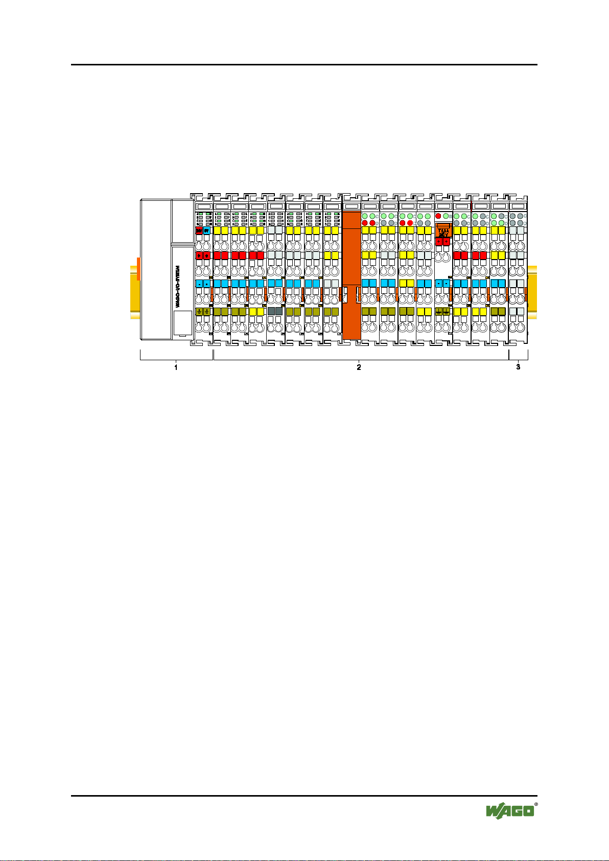
3 System Descrip tion
The WAGO-I/O-SYSTEM 750 is a modular, fieldbus-independent input/output
system (I/O system). The configuration described here consists of a fieldbus
coupler/controller (1) and the modular I/O modules (2) for any signal shapes that
form the fieldbus node together. The end module (3) completes the node and is
required for correct operation of the fieldbus node.
Figure 1: Fieldbus Node (Example)
Fieldbus couplers/controllers are available for different fieldbus systems.
The standard fieldbus couplers/controllers contain the fieldbus interface,
electronics and a power supply terminal. The fieldbus interface forms the physical
interface to the relevant fieldbus. The electronics process the data of the I/O
modules and make it available for the fieldbus communication. The 24 V system
supply and the 24 V field supply are fed in via the integrated power supply
terminal.
The fieldbus coupler/controller exchanges process data with the respective control
via the respective fieldbus. The programmable fieldbus controllers (PFC) allow
implementation of additional PLC functions. WAGO-I/O-PRO is used to program
the fieldbus controllers according to IEC 61131-3.
I/O modules for diverse digital and analog I/O signals as well as special functions
can be connected to the fieldbus coupler/controller. The communication between
the fieldbus coupler/controller and the I/O modules is carried out via an internal
bus.
The components of the WAGO-I/O-SYSTEM 750 have clear termination points,
light emitting diodes for status display, plug-in mini WSB tags and group marker
cards for labeling.
The 1, 2 or 3 wire technology supplemented by a ground wire connection allows
for direct sensor or actuator wiring.
Manual
Version 2.0.0
Page 16

16 System Description WAGO-I/O-SYSTEM 750
01
14
01
01
01
(additional positions)
WW
YY
FW --
HW
FL
-
Calendar
Year
Firmware
Hardware
Firmware
version
Internal info rmation
750-306 DeviceNet
TM
Fieldbus Coupler
3.1 Ma nu fact uri n g Num ber
The serial number indicates the delivery status directly after production. This
number is part of the labeling on the side of each component.
In addition, the serial number is printed on the cover cap of the configuration and
programming interface of the fieldbus coupler/controller, so that it can also be
read when installed.
Figure 2: Marking Area for Serial Numbers
There are two serial numbers in two rows in the side marking. They are left of the
release tab. The first 10 positions in the longer row of the serial numbers contain
version and date identifications.
Example structure of the rows: 0114010101…
week
The row order can vary depending on the production year, only the longer row is
relevant. The back part of this and the shorter row contain internal administration
information from the manufacturer.
version
version
loader
Manual
Version 2.0.0
Page 17

WAGO-I/O-SYST EM 750 System Description 17
Current version data for
1. Update
2. Update
3. Update
Production order no.
NO
only starting fr o m
Date stamp
DS
calendar week 13/2004
Software version
SW
Hardware version
HW
Firmware loader vers.
FWL
only for fieldbus
couplers/controllers
750-306 DeviceNet
TM
Fieldbus Coupler
3.2 Component Update
For the case of an update of one component, the lateral marking on each
component contains a prepared matrix.
This matrix makes columns available for altogether three updates to the entry of
the current update data, like production order number (NO; starting from calendar
week 13/2004), date stamp (DS), software version (SW), hardware version (HW)
and the firmware loader version (FWL, if available).
If the update of a component took place, the current version data are registered
into the columns of the matrix.
Additionally with the update of a fieldbus coupler or controller also the cover of
the configuration and programming interface of the fieldbus coupler or controller
is imprinted with the current production order number.
The original manufacturing information on the device's housing remains
unchanged.
3.3 Storage, Assembly and Transport
Whenever possible, the components are to be stored in their original packaging.
Likewise, the original packaging provides optimal protection during transport.
When assembling or repacking the components, the contacts must not be soiled or
damaged. The components must be stored and transported in appropriate
containers/packaging. Thereby, the ESD information is to be regarded.
Manual
Version 2.0.0
Page 18

18 System Description WAGO-I/O-SYSTEM 750
750-306 DeviceNet
TM
Fieldbus Coupler
3.4 Assem bl y Guidelines/Standar ds
• DIN 60204 Electrical equipping of machines
• DIN EN 50178 Equipping of high-voltage systems with electronic
components (replacement for VDE 0160)
• EN 60439 Low-voltage switchgear and controlgear assemblies
Manual
Version 2.0.0
Page 19
WAGO-I/O-SYST EM 750 System Description 19
750-306 DeviceNet
TM
Fieldbus Coupler
3.5 Power Supply
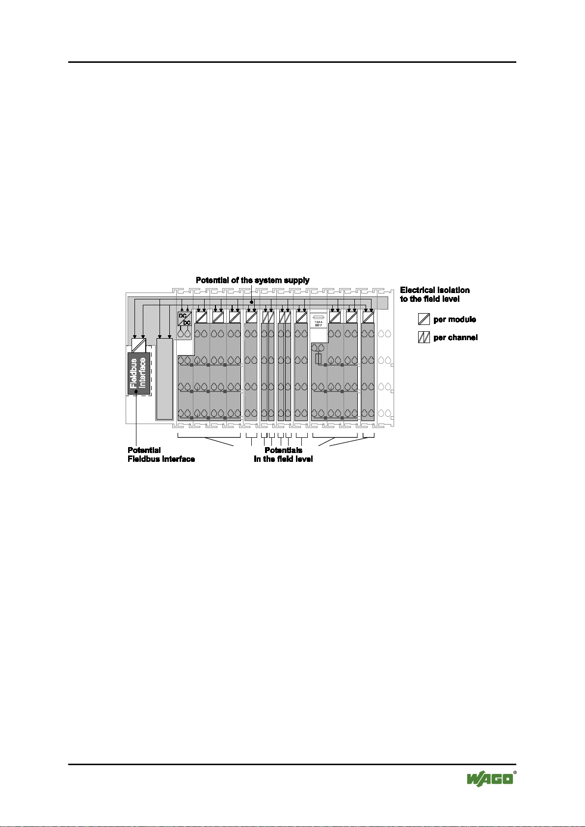
3.5.1 Isolation
Within the fieldbus node, there are three electrically isolated potentials:
• Electrically isolated fieldbus interface via transformer
• Electronics of the fieldbus couplers/controllers and the I/O modules
(internal bus)
• All I/O modules have an electrical isolation between the electronics
(internal bus, logic) and the field electronics. Some digital and analog input
modules have each channel electrically isolated, please see catalog.
Figure 3: Isolatio n for Fieldbus Couplers/Controllers (Example)
Manual
Version 2.0.0
Page 20
20 System Description WAGO-I/O-SYSTEM 750
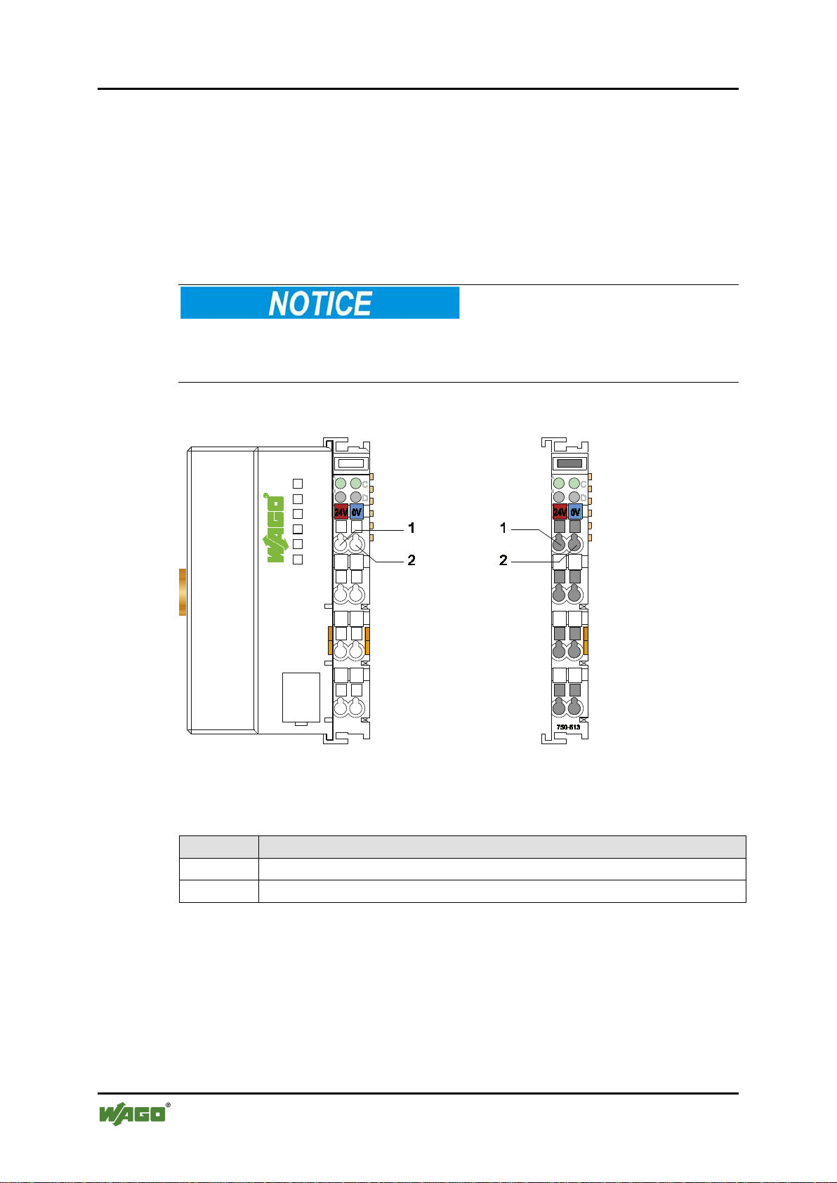
Table 3: Legend for Figure “System Supp ly via Fieldbus Coupler/Controller ( le f t) and via Internal
System Supply Module (right)”
Position
Description
1
System supply DC 24 V (-25 % … +30 %)
2
System supply 0 V
750-306 DeviceNet
TM
Fieldbus Coupler
3.5.2 System Supply
3.5.2.1 Connection
The WAGO-I/O-SYSTEM 750 requires a 24 V direct current system supply.
The power supply is provided via the fieldbus coupler/controller and, if necessary,
in addition via internal system supply modules 750-613. The power supply is
reverse voltage protected.
Do not use an incorrect voltage/frequency!
The use of an incorrect supply voltage or frequency can cause severe damage to
the components.
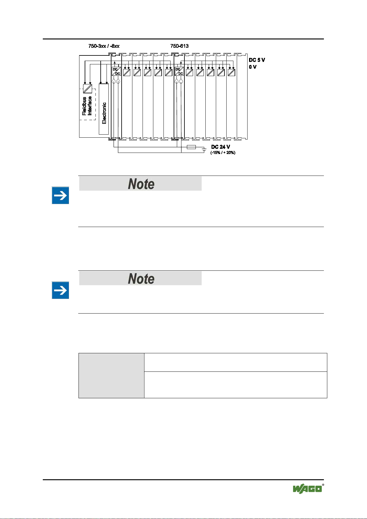
Figure 4: System Supp ly via Fieldbus Coupler/Controller (left) and via Internal System Supply
Module (right)
The fed DC 24 V supplies all internal system components, e.g. fieldbus
coupler/controller electronics, fieldbus interface and I/O modules via the internal
bus (5 V system voltage). The 5 V system voltage is galvanically connected to the
24 V system supply.
Manual
Version 2.0.0
Page 21
WAGO-I/O-SYST EM 750 System Description 21
Table 4: Alignment
Internal current
consumption*)
Current consumption via system voltage (5 V for electronics
of I/O modules and fieldbus coupler/controller).
Total current
Available current for the I/O modules. Provided by the bus
internal system supply module
*)
See current catalog, manuals, Internet
750-306 DeviceNet
TM
Fieldbus Coupler
Figure 5: System Voltage for Standard Couplers/Controllers and Extended ECO Couplers
Only reset the system simultaneously for all supply modules!
Reset the system by simultaneously switching the system supply at all supply
modules (fieldbus coupler/controller and potential supply module with bus power
supply) off and on again.
3.5.2.2 Dimensioning
Recommendation
A stable power supply cannot always be assumed. Therefore, you should use
regulated power supplies to ensure the quality of the supply voltage.
The supply capacity of the fieldbus coupler/controller or the internal system
supply module can be taken from the technical data of the components.
for I/O modules*)
power supply unit. See fieldbus coupler/controller and
Manual
Version 2.0.0
Page 22
22 System Description WAGO-I/O-SYSTEM 750
750-306 DeviceNet
TM
Fieldbus Coupler
Example:
Calculating the current consumption on the fieldbus coupler:
Internal current consumption of the coupler 350 mA at 5 V
Total current for I/O modules 1650 mA at 5 V
Sum I
(5 V) total
2000 mA at 5 V
The internal current consumption is indicated in the technical data for each bus
terminal. In order to determine the total requirement, add together the values of all
I/O modules in the node.
Please note the aggregate current for I/O modules. It may be necessary to
supply potential!
When the sum of the internal current consumption for the I/O modules exceeds
their aggregate current, you must use a supply module with bus power supply.
Install it before the position where the permissible aggregate current would be
exceeded.
Example:
Calculating the total current on a standard fieldbus coupler/controller:
A node configuration with 20 relay modules (750-517) and 30 digital input
modules (750-405) should be attached to a fieldbus coupler/controller:
Internal current consumptions 20 × 90 mA = 1800 mA at 5 V
+ 30 × 2 mA = 60 mA at 5 V
Sum of internal current consumptions 1860 mA at 5 V
However, the fieldbus coupler can only provide 1650 mA for the I/O modules.
Consequently, an internal system supply module (750-613), e. g. in the middle of
the node, should be added.
Recommendation
Utilize the smartDESIGNER feature WAGO ProServe® software to configure
fieldbus node assembly. You can test the configuration via the integrated
plausibility check.
The maximum input current of the 24 V system supply is 500 mA. The exact
electrical consumption (I
Manual
Version 2.0.0
) can be determined with the following formulas:
(V)
Page 23
WAGO-I/O-SYST EM 750 System Description 23
Fieldbus coupler or controller
I
=
Sum of all the internal current consumption of the connected
coupler/controller
Internal system supply module
I
=
Sum of all the internal current consumption of the connected
5 V × I
(5 V) total
24 V
η
(87 % Efficiency of the power supply at nominal load 24 V)
750-306 DeviceNet
TM
Fieldbus Coupler
(5 V) total
I/O modules + internal current consumption of the fieldbus
(5 V) total
I/O modules at internal system supply module
Input current I
Activate all outputs when testing the current consumption!
If the electrical consumption of a power supply point for the 24 V system
supply exceeds 500 mA, then the cause may be an improperly dimensioned
node or a defect.
During the test, you must activate all outputs.
(24 V)
=
η = 0.87
Manual
Version 2.0.0
Page 24
24 System Description WAGO-I/O-SYSTEM 750
750-306 DeviceNet
TM
Fieldbus Coupler
3.5.3 Field Supply
3.5.3.1 Connection
Sensors and actuators can be directly connected to the relevant channel of the I/O
module in 1, 2, 3 or 4 conductor connection technology. The I/O module supplies
power to the sensors and actuators. The input and output drivers of some I/O
modules require the field side supply voltage.
The fieldbus coupler/controller provides field side power (DC 24 V). In this case
it is a passive power supply without protection equipment.
Power supply modules with or without fuse holder and diagnostic capability are
available for the power supply of other field potentials (DC 24 V, AC/DC 0 …
230 V, AC 120 V, AC 230 V). The power supply modules can also be used to set
up various potential groups. The connections are connected in pairs to a power
contact.
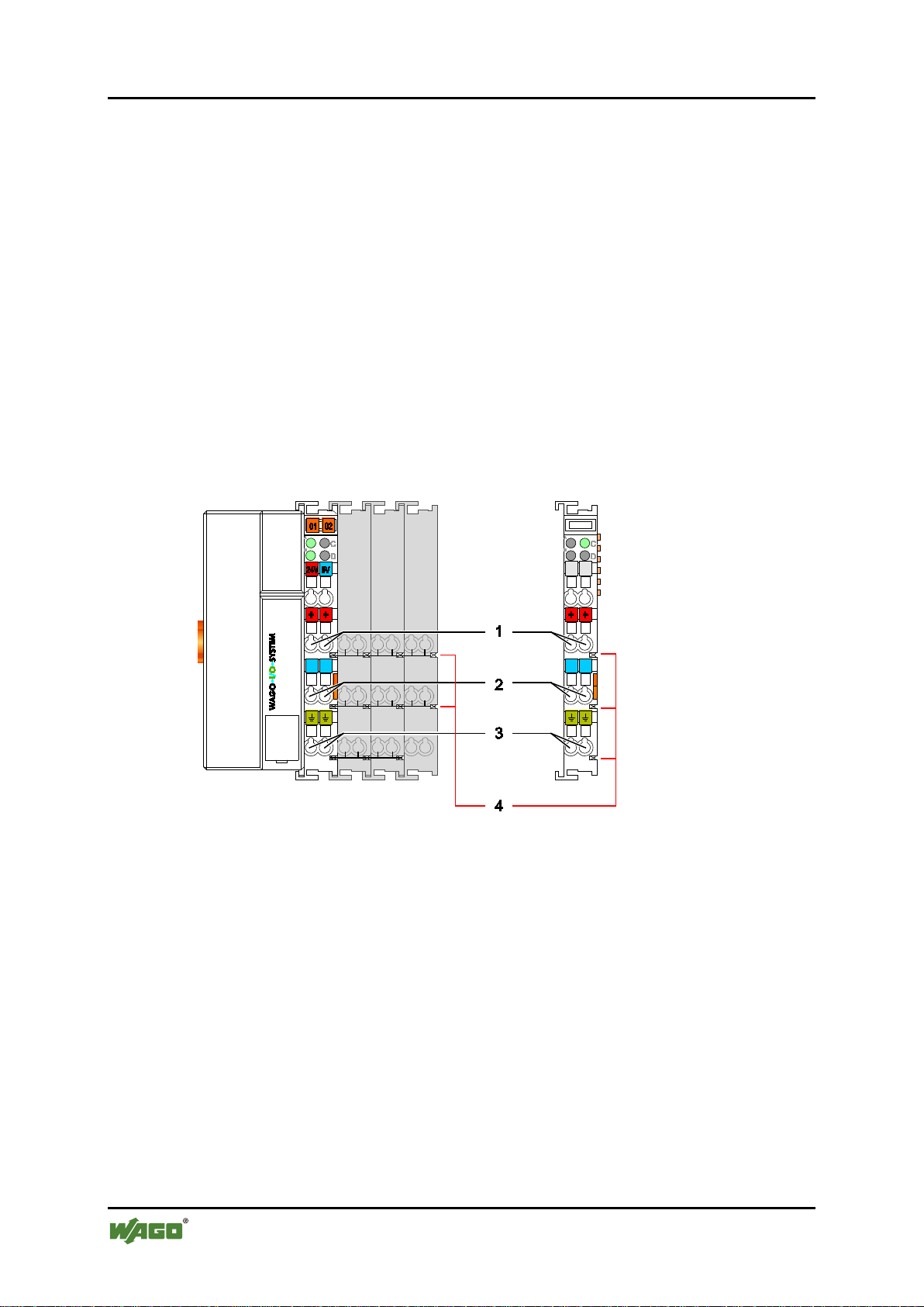
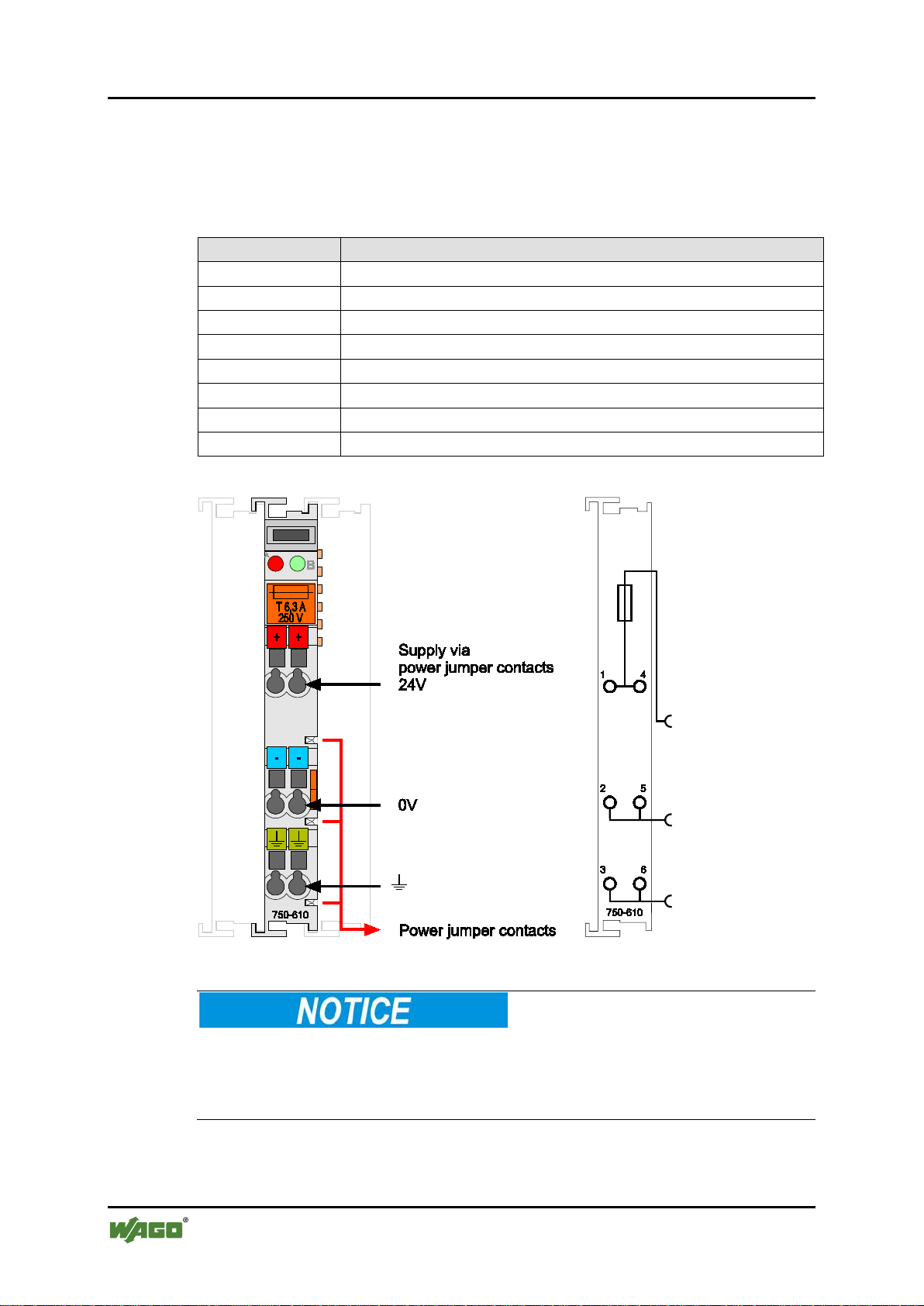
Figure 6: Field Supply for Standard Couplers/Controllers and Extended ECO Couplers
Manual
Version 2.0.0
Page 25
WAGO-I/O-SYST EM 750 System Description 25
Table 5: Legend for Figure “Field Supply for Standard Couplers/Controllers and Extended ECO
Couplers”
Field supply
1
24 V (-15 % / +20 %)
2
0 V
3
Optional ground potential
Power jumper contacts
4
Potential distribution to adjacent I/O modules
establish the ground connection when the connection to the power jumper
750-306 DeviceNet
TM
Fieldbus Coupler
The field-side power supply is automatically derived from the power jumper
contacts when snapping an I/O module.
The current load of the power contacts must not exceed 10 A on a continual basis.
By inserting an additional power supply module, the field supply via the power
contacts is disrupted. From there a new power supply occurs which may also
contain a new voltage potential.
Recontacts is disrupted!
Some I/O modules have no or very few power contacts (depending on the I/O
function). Due to this, the passing through of the relevant potential is disrupted. If
you require a field supply via power jumper contacts for subsequent I/O modules,
then you have to use a power supply module.
Note the data sheets of the I/O modules.
Use a spacer module when setting up a node with different potentials!
In the case of a node setup with different potentials, e.g. the alteration from
DC 24 V to AC 230 V, you should use a spacer module. The optical separation of
the potentials acts as a warning to heed caution in the case of wiring and
maintenance works. Thus, you can prevent the results of wiring errors.
Manual
Version 2.0.0
Page 26
26 System Description WAGO-I/O-SYSTEM 750
Table 6: Power Supply Modules
Order No.
Field Voltage
750-601
24 V DC, Supply/Fuse
750-609
230 V AC, Supply/Fuse
750-615
120 V AC, Supply/Fuse
750-617
24 V AC, Supply/Fuse
750-610
24 V DC, Supply/Fuse/Diagnosis
750-611
230 V AC, Supply/Fuse/Diagnosis
750-606
Supply Module 24 V DC, 1,0 A, Ex i
750-625/000-001
Supply Module 24 V DC, 1,0 A, Ex i (without diagnostics)
750-306 DeviceNet
TM
Fieldbus Coupler
3.5.3.2 Fusing
Internal fusing of the field supply is possible for various field voltages via an
appropriate power supply module.
Figure 7: Supply Module with Fuse Carrier (Example 750-610)
Observe the maximum power dissipation and, if required, UL requirements!
In the case of power supply modules with fuse holders, you must only use fuses
with a maximum dissipation of 1.6 W (IEC 127).
For UL approved systems only use UL approved fuses.
Manual
Version 2.0.0
Page 27
WAGO-I/O-SYST EM 750 System Description 27
750-306 DeviceNet
TM
Fieldbus Coupler
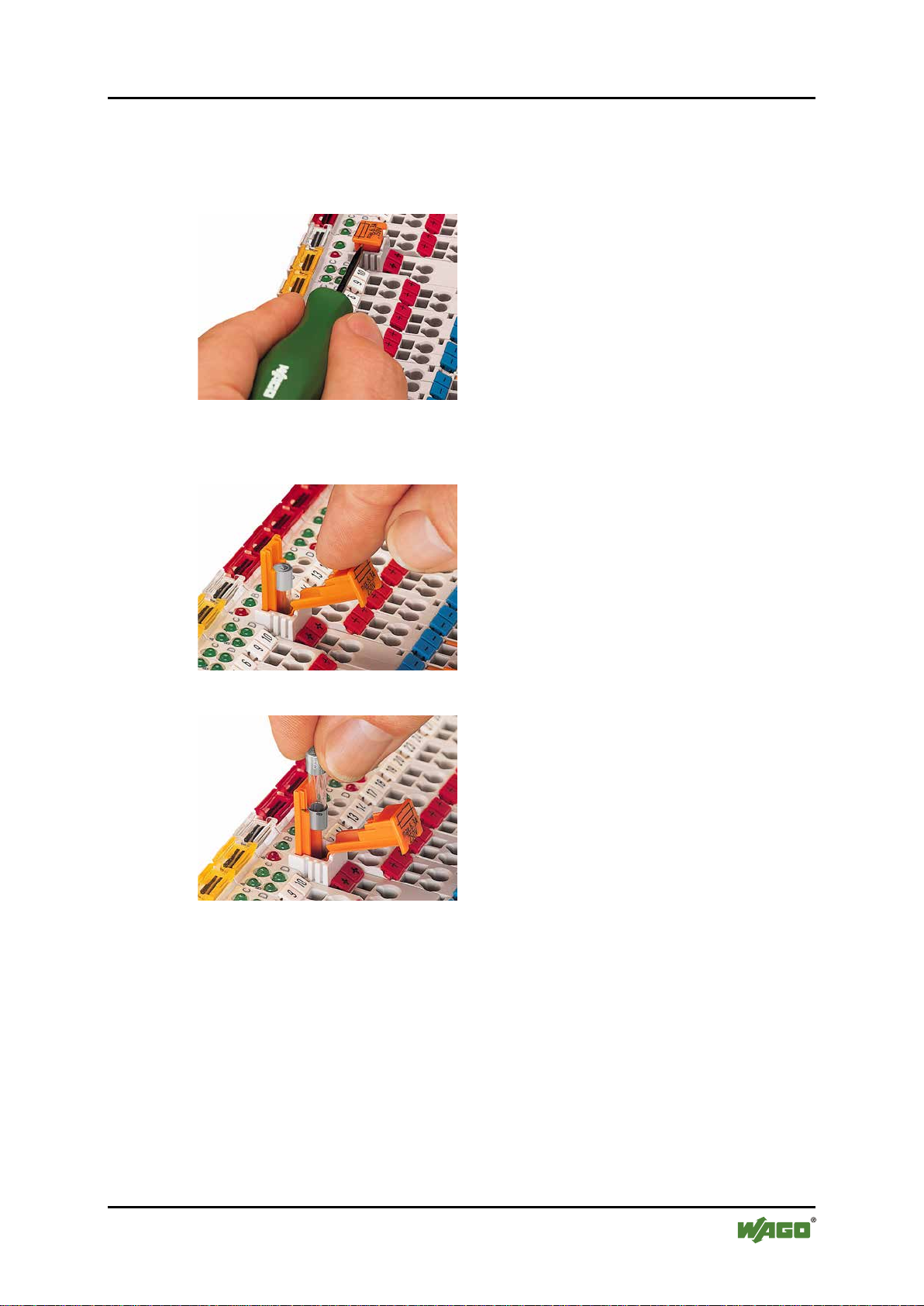
In order to insert or change a fuse, or to switch off the voltage in succeeding I/O
modules, the fuse holder may be pulled out. In order to do this, use a screwdriver
for example, to reach into one of the slits (one on both sides) and pull out the
holder.
Figure 8: Removing the Fuse Carrier
Lifting the cover to the side opens the fuse carrier.
Figure 9: Opening the Fuse Carrier
Figure 10: Cha nging the Fuse
After changing the fuse, the fuse carrier is pushed back into its original position.
Manual
Version 2.0.0
Page 28
28 System Description WAGO-I/O-SYSTEM 750
750-306 DeviceNet
TM
Fieldbus Coupler
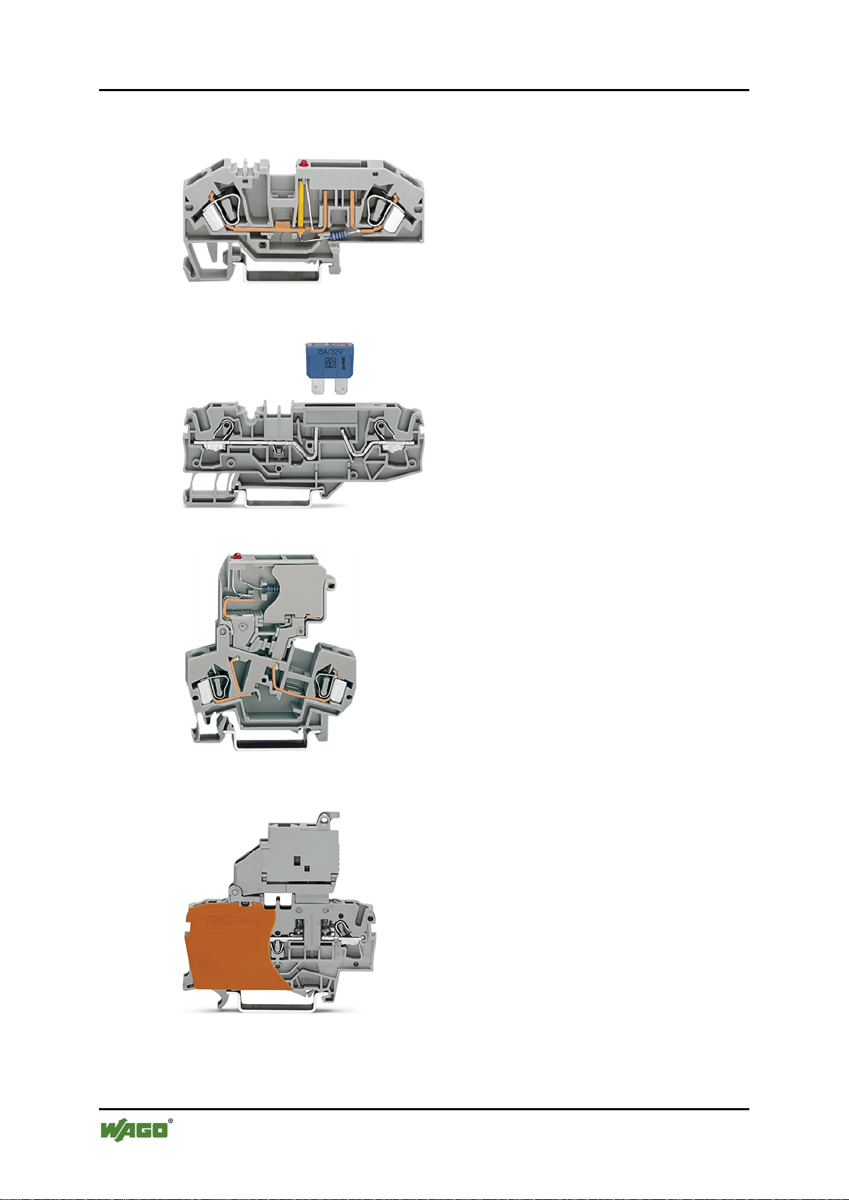
Alternatively, fusing can be done externally. The fuse modules of the WAGO
series 281 and 282 are suitable for this purpose.
Figure 11: Fuse Modules for Automotive Fuses, Series 282
Figure 12: Fuse Modules for Automotive Fuses, Series 2006
Figure 13: Fuse Modules with Pivotable Fuse Carrier, Series 281
Figure 14: Fuse Modules with Pivotable Fuse Carrier, Series 2002
Manual
Version 2.0.0
Page 29
WAGO-I/O-SYST EM 750 System Description 29
Table 7: Filter Modules for 24 V Supply
Order No.
Name
Description
750-626
Supply Filter
Filter module for system supply and field supply
bus power supply (750-613)
750-624
Supply Filter
Filter module for the 24 V field supply
(750-602, 750-601, 750-610)
750-306 DeviceNet
TM
Fieldbus Coupler
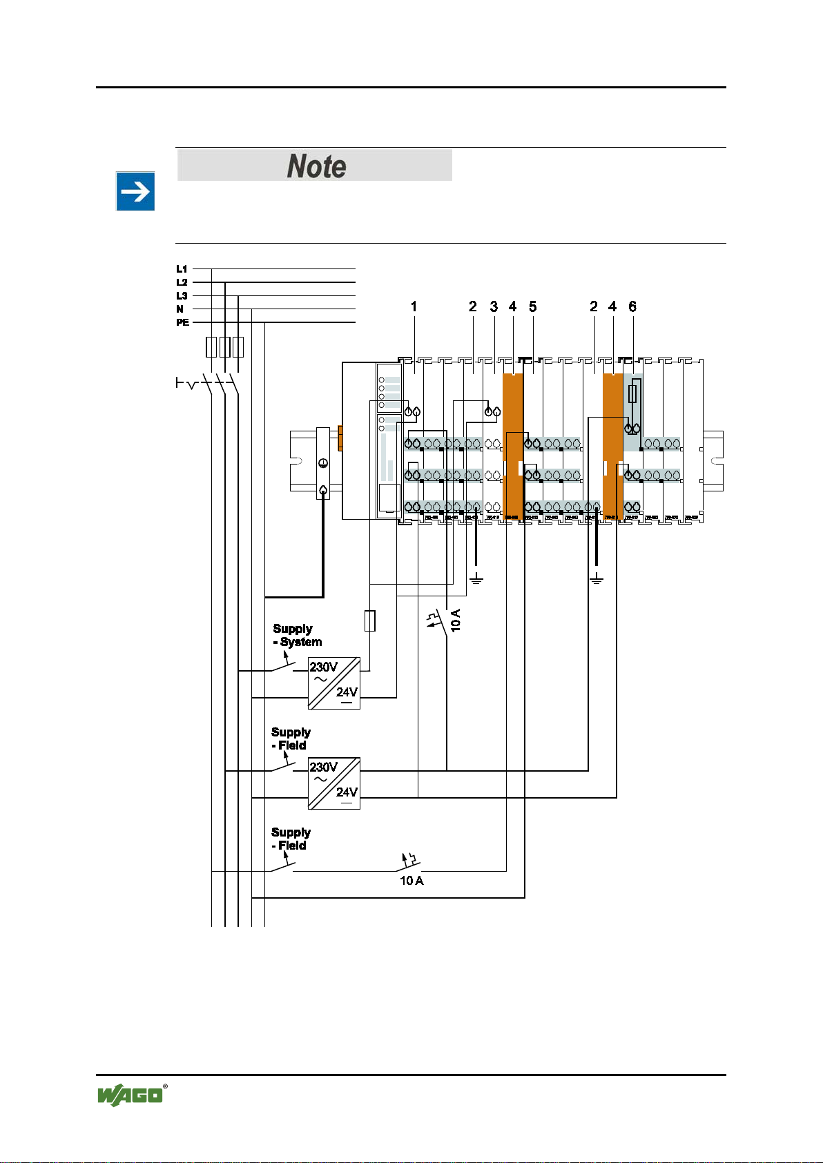
3.5.4 Supplementar y Power Supply Regulations
The WAGO-I/O-SYSTEM 750 can also be used in shipbuilding or offshore and
onshore areas of work (e. g. working platforms, loading plants). This is
demonstrated by complying with the standards of influential classification
companies such as Germanischer Lloyd and Lloyds Register.
Filter modules for 24 V supply are required for the certified operation of the
system.
(24 V, 0 V), i. e. for fieldbus coupler/controller and
Therefore, the following power supply concept must be absolutely complied with.
Figure 15: Power Supply Concept
Use a supply module for equipotential bonding!
Use an additional 750-601/ 602/ 610 Supply Module behind the 750-626 Filter
Module if you want to use the lower power jumper contact for equipotential
bonding, e.g., between shielded connections and require an additional tap for this
potential.
Manual
Version 2.0.0
Page 30
30 System Description WAGO-I/O-SYSTEM 750
750-306 DeviceNet
TM
Fieldbus Coupler
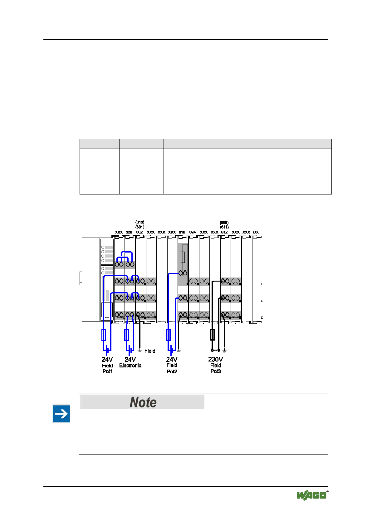
3.5.5 Supply Example
SupplSggggggggggggggggg
The system supply and the field supply shall be separated!
You should separate the system supply and the field supply in order to ensure bus
operation in the event of a short-circuit on the actuator side.
Figure 16: Supply Example for Standard Couplers/Controllers
Manual
Version 2.0.0
Page 31

WAGO-I/O-SYST EM 750 System Description 31
Table 8: Legend for Figure “Supply Example for Fieldbus Coupler/Controller”
Pos.
Description
1
Power Supply on coupler via external Supply Module
2
Power Supply with optional ground
3
Internal System Supply Module
4
Separation module recommended
5
Supply Module passive
6
Supply Module with fuse carrier/diagnostics
750-306 DeviceNet
TM
Fieldbus Coupler
Manual
Version 2.0.0
Page 32

32 System Description WAGO-I/O-SYSTEM 750
Table 9: WAGO Power Supply Units (Selection)
WAGO Power
Supply Unit
Description
787-612
Primary switched mode;
DC 24 V; 2,5 A Input nominal voltage AC 230 V
787-622
Primary switched mode;
DC 24 V; 5 A Input nominal voltage AC 230 V
787-632
Primary switched mode;
DC 24 V; 10 A Input nominal voltage AC 230/115 V
Rail-mounted modules with universal mounting carrier
288-809
AC 115 V/DC 24 V; 0,5 A
288-810
AC 230 V/DC 24 V; 0,5 A
288-812
AC 230 V/DC 24 V; 2 A
288-813
AC 115 V/DC 24 V; 2 A
750-306 DeviceNet
TM
Fieldbus Coupler
3.5.6 Power Supply Unit
The WAGO-I/O-SYSTEM 750 requires a 24 VDC voltage (system supply).
Recommendation
A stable power supply cannot always be assumed everywhere. Therefore, you
should use regulated power supplies to ensure the quality of the supply voltage
(see also table “WAGO power supply units”).
For brief voltage dips, a buffer (200 µF per 1 A load current) must be provided.
Power failure time not acc. IEC 61131-2!
Note that the power failure time of 10 ms acc. IEC 61131-2 is not maintained in a
maximum configuration.
The power demand must be determined individually depending on the entry point
of the field supply. All loads through field devices and I/O modules must be taken
into account. The field supply also impacts the I/O modules because the input and
output drivers of some I/O modules require the voltage of the field supply.
System and field supply must be isolated!
The system supply and field supply must be isolated to ensure bus operation in the
event of short circuits on the actuator side.
Manual
Version 2.0.0
Page 33

WAGO-I/O-SYST EM 750 System Description 33
Table 10: WAGO Ground Wire Termi nals
Order No.
Description
283-609
1-conductor ground (earth) terminal block make an automatic contact
Note: Also order the end and intermediate plate (283-320).
750-306 DeviceNet
TM
Fieldbus Coupler
3.6 Grounding
3.6.1 Grounding the DIN Rail
3.6.1.1 Framework Assembly
When setting up the framework, the carrier rail must be screwed together with the
electrically conducting cabinet or housing frame. The framework or the housing
must be grounded. The electrical connection is established via the screw. Thus,
the carrier rail is grounded.
Ensure sufficient grounding is provided!
You must take care to ensure the flawless electrical connection between the
carrier rail and the frame or housing in order to guarantee sufficient grounding.
3.6.1.2 Insulated Assembly
Insulated assembly has been achieved when there is constructively no direct
ohmic contact between the cabinet frame or machine parts and the carrier rail.
Here, the earth ground must be set up via an electrical conductor in accordance
with valid national safety regulations.
Recommendation
The optimal setup is a metallic assembly plate with grounding connection which
is electrically conductive linked to the carrier rail.
The separate grounding of the carrier rail can be easily set up with the aid of the
WAGO ground wire terminals.
to the carrier rail; conductor cross section: 0.2 mm² … 16 mm2
Manual
Version 2.0.0
Page 34

34 System Description WAGO-I/O-SYSTEM 750
750-306 DeviceNet
TM
Fieldbus Coupler
3.6.2 Grounding Function
The grounding function increases the resistance against electro-magnetic
interferences. Some components in the I/O system have a carrier rail contact that
dissipates electro-magnetic interferences to the carrier rail.
Figure 17: Carrier Rail Co ntact (Example)
Ensure sufficient grounding is provided!
You must take care to ensure the direct electrical connection between the carrier
rail contact and the carrier rail.
The carrier rail must be grounded.
For information on carrier rail properties, see section “Mounting” > … > “Carrier
Rail Properties”.
The bottom CAGE CLAMP
connection of a field-side functional ground. This potential is made available to
the I/O module arranged on the right through the spring-loaded contact of the
three power contacts. Some I/O modules are equipped with a knife-edge contact
that taps this potential. This forms a potential group with regard to functional
ground with the I/O module arranged on the left.
®
connectors of the supply modules enable optional
Manual
Version 2.0.0
Page 35

WAGO-I/O-SYST EM 750 System Description 35
750-306 DeviceNet
TM
Fieldbus Coupler
3.7 Shielding
3.7.1 General
Use of shielded cables reduces electromagnetic interference and thus increases
signal quality. Measurement errors, data transmission errors and interference due
to excessive voltage can be prevented.
Connect the cable shield to the ground potential!
Integrated shielding is mandatory to meet the technical specifications in regards to
measuring accuracy. Connect the cable shield and ground potential at the inlet to
the cabinet or housing. This allows induced interference to dissipate and to be
kept away from devices in the cabinet or housing.
Figure 18: Cable Shield at Ground Potential
Improve shielding performance by placing the shield over a large area!
Higher shielding performance is achieved via low-impedance connection between
shield and ground. For this purpose, connect the shield over a large surface area,
e.g., WAGO shield connecting system. This is especially recommended for largescale systems where equalizing current or high impulse-type currents caused by
atmospheric discharge may occur.
Keep data and signal lines away from sources of interference!
Route data and signal lines separately from all high voltage cables and other
sources of high electromagnetic emission (e.g., frequency converter or drives).
3.7.2 Bus Cables
The shielding of the bus line is described in the respective configuration
guidelines and standards of the bus system.
Manual
Version 2.0.0
Page 36

36 System Description WAGO-I/O-SYSTEM 750
Figure 19: Examples of the WAGO Shield Connecting System
750-306 DeviceNet
TM
Fieldbus Coupler
3.7.3 Signal Lines
I/O modules for analog signals and some interface I/O modules are equipped with
shield clamps.
Use shielded signal lines!
Only use shielded signal lines for analog signals and I/O modules which are
equipped with shield clamps. Only then can you ensure that the accuracy and
interference immunity specified for the respective I/O module can be achieved
even in the presence of interference acting on the signal cable.
3.7.4 WAGO Shield Connecting System
The WAGO shield connecting system consists of shield clamping saddles,
busbars and various mounting carriers. These components can be used to achieve
many different configurations.
Figure 20: Application of the WAGO Shield Connecting System
Manual
Version 2.0.0
Page 37

WAGO-I/O-SYST EM 750 Device Description 37
750-306 DeviceNet
TM
Fieldbus Coupler
4 Device Description
The DeviceNetTM Fieldbus Coupler 750-306 links the WAGO-I/O-SYSTEM 750
as a slave to the DeviceNetTM fieldbus system.
This fieldbus coupler can be used for applications in mechanical and systems
engineering, as well as in the processing industry.
The fieldbus connection is made via 231 series 5-pin plug connector of the WAGO
MULTI CONNECTION SYSTEM (MCS).
The DIP switch can be used to specify baud rate and station address of the
fieldbus coupler.
In the Fieldbus Coupler, all input signals from the sensors are combined. After
connecting the Fieldbus Coupler, the Fieldbus Coupler determines which I/O
modules are on the node and creates a local process image from these. Analog and
specialty module data is sent via words and/or bytes; digital data is grouped bitby-bit.
The local process image is divided into two data zones containing the data
received and the data to be sent.
The process data is sent via the DeviceNetTM fieldbus to a control system for
further processing. The process output data is sent via the DeviceNetTM fieldbus.
The data of the analog modules is mapped first into the process image. The
modules are mapped in the order of their physical position after the Coupler.
The bits of the digital modules are combined into bytes and then mapped after the
analog ones in the process image. If the number of digital I/Os is greater than 8
bits, the Fieldbus Coupler automatically begins a new byte.
The fieldbus coupler supports the DeviceNetTM “Bit Strobe” function where the
function is limited to the extent that only the status byte is supplied.
Manual
Version 2.0.0
Page 38

38 Device Description WAGO-I/O-SYSTEM 750
750-306 DeviceNet
TM
Fieldbus Coupler
4.1 View
The view below shows the three parts of the device:
• The left side shows the fieldbus connection and a DIP switch to set both the
node ID and baud rate.
• LEDs for operation status, bus communication, error messages and
diagnostics, as well as the service interface are in the middle area.
• The right side shows the power supply unit for the system supply and for the
field supply of the attached I/O modules via power jumper contacts.
LEDs show the status of the operating voltage for the system and field
supply (jumper contacts).
Figure 21: View DeviceNet
TM
Fieldbus Coupler
Manual
Version 2.0.0
Page 39

WAGO-I/O-SYST EM 750 Device Description 39
Table 11: Legend for Figure “View DeviceNetTM Fieldbus Coupler”
Designation
OVERFL,
CONNECT
Group marking carrier (retractable) with
WSB markers
“Device Description” >
“Display Elements”
“Connect Devices” > “Data
Contacts/I nternal Bus”
“Connect Devices” >
the CAGE CLAMP®”
“Connect Devices” >
the CAGE CLAMP®”
“Connect Devices” >
Field Supply”
“Mounting” >
Devices”
“Connect Devices” >
the CAGE CLAMP®”
“Connect Devices” >
Field Supply”
“Connect Devices” >
the CAGE CLAMP®”
“Connect Devices” >
Field Supply”
“Device Description” >
“Operating Elements”
“Device Description” >
“Operating Elements”
“Mounting” > “Inserti ng
and Removing Devices”
Fieldbus Data contacts connection, 231 Series
(MCS)
“Device Description“ >
“Connectors“
750-306 DeviceNet
TM
Fieldbus Coupler
Pos.
RUN,
1
BUS OFF,
2 ---
Status LEDs Fieldbus
additional marking possibility on two miniature
Meaning Details see Section
“Device Description” >
“Display Elements”
---
3 A, B or C Status LED’s System/Field Supply
4 --- Data Contacts
5 24 V, 0 V CAGE CLAMP® Connections System Supply
®
6 +
CAGE CLAMP
24 VDC
Connections Field Supply
7 --- Power Jumper Contact 24 VDC
8 --- Unlockin g Lu g
“Connecting a conductor to
“Connecting a conductor to
“Power Contacts/
“Inserting and Removi ng
9 - CAGE CLAMP® Connections Field Supply 0 V
10 --- Po wer Jumper Contact 0 V
11 (Ground)
12 --- Power Jumper Contact (Ground)
13 --- Service Interface (open flap)
16 --- DIP Switch
15 --- Locking Disc
16 ---
CAGE CLAMP
(Ground)
®
Connections Field Supply
“Connecting a conductor to
“Power Contacts/
“Connecting a conductor to
“Power Contacts/
Manual
Version 2.0.0
Page 40

40 Device Description WAGO-I/O-SYSTEM 750
750-306 DeviceNet
TM
Fieldbus Coupler
4.2 Connectors
4.2.1 Device Supply
The device is powered via terminal blocks with CAGE CLAMP® connections.
The device supply generates the necessary voltage to power the electronics of the
device and the internal electronics of the connected I/O modules.
The fieldbus interface is galvanically separated to the electrical potential of the
device.
Figure 22: Device Supply
Manual
Version 2.0.0
Page 41

WAGO-I/O-SYST EM 750 Device Description 41
Table 12: Pin Assignment for the Fieldbus Connection, Series 231 (MCS)
PIN
Signal
Code*
Description
5
V+
red
11 V … 25 V
4
CAN_H
white
CAN Signal
High
3
Drain shield
Shield termination
2
CAN_L
blue
CAN Signal
Low
1
V-
black
0 V
*
according to DeviceNetTM specification, identical to the conductors of the
DeviceNetTM cable
750-306 DeviceNet
TM
Fieldbus Coupler
4.2.2 Fieldbus Connection
The fieldbus connection for DeviceNetTM is made via Series 231 5-pin plug
connector from the MULTI CONNECTION SYSTEM (MCS). A connector
(OpenStyle) is the counterpart. The 231-305/010-000/050-000 connector is
included.
Figure 23: Fieldbus Connections, Series 231 (MCS)
To connect small conductor cross-sections, an insulation stop of series 231-670
(white), 231-671 (light gray) or 231-672 (dark gray) should be used due to their
flexibility. The insulating stop prevents the conductor from deforming when
pushed against the conductor stop. As a result, the conductor insulation may be
clamped, causing intermittent contact or no contact at all. The marking of the
connector, as well as housing parts, test plugs with cable and male connectors for
cable extensions are available.
The connection point is lowered for mounting into an 80 mm-high switchgear
cabinet after connector attachment.
DC/DC converters and optocouplers in the fieldbus interface electrically isolate
the fieldbus system and the electronics.
Manual
Version 2.0.0
Page 42

42 Device Description WAGO-I/O-SYSTEM 750
Table 13: Display Elements Fieldbus Status
LED
Color
Meaning
OVERFL
red
Indicates an error or defect on the fieldbus coupler
RUN
green
Indicates that the fieldbus coupler is operational
BUS OFF
red
Indicates an error or malfunction in the network
CONNEC
T
green
Indicates that the fieldbus coupler is ready for network
communication
Table 14: Display Elements Node Status
LED
Color
Meaning
I/O
red/green/
orange
Indicates the operation of the node and signals via a blink code faults
encountered.
Table 15: Display Elements Supply Voltage
LED
Color
Meaning
A
green
indicates the status of the operating voltage – system
B
green
indicates the status of the operating voltage – power jumper contacts
750-306 DeviceNet
TM
Fieldbus Coupler
4.3 Display Elements
The operating condition of the fieldbus coupler or the node is displayed with the
help of illuminated indicators in the form of light-emitting diodes (LEDs).
The LED information is routed to the top of the case by light guides. In some
cases, the LEDs are multi-colored (red, green or orange).
Figure 24: Display Elements
+
For the diagnostics of the different domains fieldbus, node and supply voltage, the
LEDs can be divided into three groups:
+
+
More information about the LED Signaling
Read the detailed description for the evaluation of the displayed LED state in the
section “Diagnostics” > … > “LED Signaling”.
Manual
Version 2.0.0
Page 43

WAGO-I/O-SYST EM 750 Device Description 43
Table 16: Legend for Figure “Service Interface (Closed and Opened Flap)”
Number
Description
1
Open closed
2
View Service Interface
750-306 DeviceNet
TM
Fieldbus Coupler
4.4 Operating Elements
4.4.1 Service Interface
The service interface is located behind the flap.
It is used for the communication with the WAGO-I/O-CHECK and for
downloading the firmware updates.
Figure 25: Service Interface (Closed and Opened Flap)
Device must be de-energized!
To prevent damage to the device, unplug and plug in the communication cable
only when the device is de-energized!
The connection to the 4-pin header under the cover flap can be realized via the
communication cables with the item numbers750-920 and 750-923 or via the
WAGO radio adapter with the item number 750-921.
Manual
Version 2.0.0
Page 44

44 Device Description WAGO-I/O-SYSTEM 750
Table 17: Setting the Baud Rate via DIP S witch
Baud rate
Slide switch 7
Slide switch 8
125 kBaud (default)
OFF
OFF
250 kBaud
ON
OFF
500 kBaud
OFF
ON
not permitted
ON
ON
- ON
- OFF
Figure 27: Example with Baud rate Sent to 250 kBaud
750-306 DeviceNet
TM
Fieldbus Coupler
4.4.2 DIP Switch
Figure 26: DIP Switch
The DIP switch is used to set the baud rate of the fieldbus coupler and to set the
DeviceNetTM station address (relating to DeviceNetTM, also called “MAC ID”).
Settings are made by moving the slide switches to “ON” or “OFF”.
The position of the individual slide switches is only evaluated when turning on the
fieldbus coupler, i.e., changes are applied when the power supply for the fieldbus
coupler is turned OFF then ON again.
4.4.2.1 Baud Rate Setting
The baud rate is set using slide switches 7 and 8 of the DIP switch. 3 different
baud rates are supported.
Example:
Setting the baud rate to 250 kBaud
Manual
Version 2.0.0
Page 45

WAGO-I/O-SYST EM 750 Device Description 45
- ON 20 = 1
- OFF
- OFF
- ON 23 = 8
- ON 24 = 16
- OFF
Figure 28: Example with Station Address Set to 25
750-306 DeviceNet
TM
Fieldbus Coupler
4.4.2.2 Station address
The station address is set using slide switches 1 to 6.
The binary significance of the individual slide switches increases in the direction
of the slide switch numbers. Slide switch 1 is used to set the lowest bit with a
significance of 20 and slide switch 6 to set the highest bit with a significance of 25.
If slide switch 1 is set to “ON”, “MAC ID” 1 is set, if slide switch 1 and 4 are set
to “ON”, “MAC ID” 9 is set ((20 + 23).
Station addresses in the range of 0 (all slide switches set to “OFF”) to 63 (all slide
switches set to “ON”) can be set for the DeviceNetTM fieldbus nodes. The station
address is set to 1 when delivered.
Example:
Setting the station address to 25.
Manual
Version 2.0.0
Page 46

46 Device Description WAGO-I/O-SYSTEM 750
Table 18: Technical Data, Device Data
Width
51 mm
Height (from upper-edge of DIN35 rail)
65 mm
Depth
100 mm
Weight
approx. 195 g
Degree of protection
IP20
Table 19: Technical Data, System Data
Number of I/O modules
64 with scanner
Number of I/O points
approx. 6000 (master/slave dependent)
Transmission medium
Shielded Cu cable
Drop cable: 2 x 0.2 mm2 + 2 x 0.32 mm2
Bus segment length
100 m ... 500 m
(depending on baud rate/cable)
Network length
acc. specification IEEE 802.3,
stub line length for all baud rates 6 m
Baud rate
125 kBaud, 250 kBaud, 500 kBaud
Buscoupler connection
5-pin male connector, Series 231 (MCS)
Protocols
DeviceNetTM
Number of I/O modules
64
Input process image
max
512 bytes
Output process image
max
512 bytes
Configuration
via PC or PLC
Table 20: Technical Data, DeviceNet
TM
fieldbus
DeviceNetTM characteristics
“Polled I/O Message Connection”,
“Group 2 only Slave”
750-306 DeviceNet
TM
Fieldbus Coupler
4.5 Technical Data
4.5.1 Device Data
4.5.2 System Data
max
max
4.5.3 DeviceNetTM Fieldbus
Remote bus cable: 2 x 0.82 mm2 + 2 x 1.7
mm2
Manual
Version 2.0.0
“Strobed I/O Message Connection”,
“Change of State”/“Cyclic Message Connection”,
Page 47

WAGO-I/O-SYST EM 750 Device Description 47
Table 21: Technical Data, Power Supply
Voltage via power jumper contacts
24 VDC (-15% ... +20%)
Current via power jumper contacts
max.
10 ADC
Power supply efficiency
at nominal
load
87%
Internal current consumption
350 mA at 5 V
Current consumption via
- CAN interface
< 120 mA at 11 V
Total current for I/O modules
1650 mA at 5 V
Electrical isolation
500 V system/supply
Table 22: Technical Data, Accessories
Pluggable connectors
Plug connectors 231-305/010-000/050-000 for
MCS male connector (included)
Marking
Miniature WSB Quick marking system
EDS Files
Download via http://www.wago.com
Table 23: Technical Data – Field Wiring
Wire connection
CAGE CLAMP®
Cross section
0.08 mm² … 2.5 mm², AWG 28 … 14
Stripped lengths
8 mm … 9 mm / 0.33 in
Table 24: Technical Data – Power Jumper Contacts
Power jumper contacts
Spring contact, self-cleaning
Voltage drop at I
max.
< 1 V/64 modules
Table 25: Technical Data – Data Contacts
Data contacts
Slide contact, hard gold plated, selfcleaning
750-306 DeviceNet
TM
Fieldbus Coupler
4.5.4 Supply
typ.
- Power supply
4.5.5 Accessories
4.5.6 Connection Type
< 500 mA at 24 V
Manual
Version 2.0.0
Page 48

48 Device Description WAGO-I/O-SYSTEM 750
Table 26: Technical Data – Climatic Environ mental Conditions
Operating temperature range
0 °C … 55 °C
Operating temperature r a nge for
temperature range (750-xxx/025-xxx)
−20 °C … +60 °C
Storage temperature range
−25 °C … +85 °C
Storage temperature range for
temperature range (750-xxx/025-xxx)
−40 °C … +85 °C
Relative humidity
Max. 5 % … 95 % without condensation
Resistance to harmful substances
Acc. to IEC 60068-2-42 and
IEC 60068-2-43
Maximum pollutant concentration at
SO2 ≤ 25 ppm
H2S ≤ 10 ppm
Special conditions
Ensure that additional measures for
– ionizing radiation
Table 27: Technical Data – Mechanical Strength acc. to IEC 61131-2
Test specification
Frequency range
Limit value
IEC 60068-2-6 vibration
5 Hz ≤ f < 9 Hz
1.75 mm amplitude (permanent)
3.5 mm amplitude (short term)
9 Hz ≤ f < 150 Hz
0.5 g (permanent)
1 g (short term)
Note on vibration test:
a)
Frequency change: max. 1 octave/minute
b)
Vibration direction: 3 axes
IEC 60068-2-27 shock
15 g
Note on shock test:
a)
A Type of shock: half sine
b)
Shock duration: 11 ms
c)
Shock direction: 3x in positive and 3x in negative
direction for each of the three mutually
perpendicular axes of the test specimen
IEC 60068-2-32 free fall
1 m (module in original packing)
750-306 DeviceNet
TM
Fieldbus Coupler
4.5.7 Climatic Environment a l Conditions
components with extended
components with extended
relative humidity < 75 %
components are taken, which are used in
an environment involving:
– dust, caustic vapors or gases
4.5.8 Mechanical Strength acc. to IEC 61131-2
Manual
Version 2.0.0
Page 49

WAGO-I/O-SYST EM 750 Device Description 49
Conformity Marking
ODVA
“Open DeviceNet Vendors Association” certified
TÜV 07 ATEX 554086 X
I M2 Ex d I Mb
II 3 D Ex tc IIIC T135°C Dc
IECEx TUN 09.0001 X
Ex d I Mb
Ex tc IIIC T135°C Dc
CULUS
ANSI/ISA 12.12.01
Class I, Div2 ABCD T4
TUEV 12.1297 X
Ex nA IIC T4 Gc
750-306 DeviceNet
TM
Fieldbus Coupler
4.6 Approvals
More information about approvals.
Detailed references to the approvals are listed in the document “Overview
Approvals WAGO-I/O-SYSTEM 750”, which you can find via the internet
under: www.wago.com > SERVICES > DOWNLOADS > Additional
documentation and information on automation products > WAGO-I/O-SYSTEM
750 > System Description.
The following approvals have been granted to 750-306 fieldbus
coupler/controller:
CULUS
UL508
The following Ex approvals have been granted to 750-306 fieldbus
coupler/controller:
II 3 G Ex nA IIC T4 Gc
Ex nA IIC T4 Gc
Korea Certification MSIP-REM-W43-FBC750
Brasilian-
Ex
Manual
Version 2.0.0
Page 50

50 Device Description WAGO-I/O-SYSTEM 750
750-306 DeviceNet
TM
Fieldbus Coupler
The following ship approvals have been granted to 750-306 fieldbus
coupler/controller:
ABS (American Bureau of Shipping)
Federal Maritime and Hydrographic Agency
BV (Bureau Veritas)
DNV (Det Norske Veritas) Class B
GL (Germanischer Lloyd) Cat. A, B, C, D (EMC 1)
KR (Korean Register of Shipping)
LR (Lloyd’s Register) Env. 1, 2, 3, 4
NKK (Nippon Kaiji Kyokai)
PRS (Polski Rejestr Statków)
RINA (Registro Italiano Navale)
Manual
Version 2.0.0
Page 51

WAGO-I/O-SYST EM 750 Device Description 51
750-306 DeviceNet
TM
Fieldbus Coupler
4.7 Standards and Guidelines
750-306 meets the following requirements on emission and immunity of
interference:
EMC CE-Immunity to interference acc. to EN 61000-6-2
EMC CE-Emission of interference acc. to EN 61000-6-3
EMC marine applications-Immunity
to interference acc. to Germanischer Llo yd
EMC marine applications-Emission
of interference acc. to Germanischer Lloyd
Manual
Version 2.0.0
Page 52

52 Mounting WAGO-I/O-SYSTEM 750
750-306 DeviceNet
TM
Fieldbus Coupler
5 Mounting
5.1 Installation Position
Along with horizontal and vertical installation, all other installation positions are
allowed.
Use an end stop in the case of vertical mounting!
In the case of vertical assembly, an end stop has to be mounted as an additional
safeguard against slipping.
WAGO order no. 249-116 End stop for DIN 35 rail, 6 mm wide
WAGO order no. 249-117 End stop for DIN 35 rail, 10 mm wide
5.2 O verall Configur ation
The maximum total length of a fieldbus node without fieldbus coupler/controller
is 780 mm including end module. The width of the end module is 12 mm. When
assembled, the I/O modules have a maximum length of 768 mm.
Examples:
• 64 I/O modules with a 12 mm width can be connected to a fieldbus
coupler/controller.
• 32 I/O modules with a 24 mm width can be connected to a fieldbus
coupler/controller.
Exception:
The number of connected I/O modules also depends on the type of fieldbus
coupler/controller is used. For example, the maximum number of stackable I/O
modules on one PROFIBUS DP/V1 fieldbus coupler/controller is 63 with no
passive I/O modules and end module.
Observe maximum total length of a fieldbus node!
The maximum total length of a fieldbus node without fieldbus coupler/controller
and without using a 750-628 I/O Module (coupler module for internal data bus
extension) may not exceed 780 mm.
Also note the limitations of individual fieldbus couplers/controllers.
Manual
Version 2.0.0
Page 53

WAGO-I/O-SYST EM 750 Mounting 53
750-306 DeviceNet
TM
Fieldbus Coupler
Increase the total length using a coupler module for internal data bus
extension!
You can increase the total length of a fieldbus node by using a 750-628 I/O
Module (coupler module for internal data bus extension). For such a
configuration, attach a 750-627 I/O Module (end module for internal data bus
extension) after the last I/O module of a module assembly. Use an RJ-45 patch
cable to connect the I/O module to the coupler module for internal data bus
extension of another module block.
This allows you to segment a fieldbus node into a maximum of 11 blocks with
maximum of 10 I/O modules for internal data bus extension.
The maximum cable length between two blocks is five meters.
More information is available in the manuals for the 750-627 and 750-628 I/O
Modules.
Manual
Version 2.0.0
Page 54

54 Mounting WAGO-I/O-SYSTEM 750
750-306 DeviceNet
TM
Fieldbus Coupler
5.3 Mounting onto Carrier Rail
5.3.1 Carrier Rail Properties
All system components can be snapped directly onto a carrier rail in accordance
with the European standard EN 50022 (DIN 35).
Do not use any third-party carrier rails without approval by WAGO!
WAGO Kontakttechnik GmbH & Co. KG supplies standardized carrier rails that
are optimal for use with the I/O system. If other carrier rails are used, then a
technical inspection and approval of the rail by WAGO Kontakttechnik GmbH &
Co. KG should take place.
Carrier rails have different mechanical and electrical properties. For the optimal
system setup on a carrier rail, certain guidelines must be observed:
• The material must be non-corrosive.
• Most components have a contact to the carrier rail to ground electro-
magnetic disturbances. In order to avoid corrosion, this tin-plated carrier rail
contact must not form a galvanic cell with the material of the carrier rail
which generates a differential voltage above 0.5 V (saline solution of 0.3 %
at 20°C).
• The carrier rail must optimally support the EMC measures integrated into
the system and the shielding of the I/O module connections.
• A sufficiently stable carrier rail should be selected and, if necessary, several
mounting points (every 20 cm) should be used in order to prevent bending
and twisting (torsion).
• The geometry of the carrier rail must not be altered in order to secure the
safe hold of the components. In particular, when shortening or mounting the
carrier rail, it must not be crushed or bent.
• The base of the I/O components extends into the profile of the carrier rail.
For carrier rails with a height of 7.5 mm, mounting points are to be riveted
under the node in the carrier rail (slotted head captive screws or blind
rivets).
• The medal springs on the bottom of the housing must have low-impedance
contact with the DIN rail (wide contact surface is possible).
Manual
Version 2.0.0
Page 55

WAGO-I/O-SYST EM 750 Mounting 55
Table 28: WAGO DIN Rail
Order number
Description
210-113 /-112
35 x 7.5;
1 mm;
steel yellow chromated; slotted/unslotted
210-114 /-197
35 x 15;
1.5 mm;
steel yellow chromated; slotted/unslotted
210-118
35 x 15;
2.3 mm;
steel yellow chromated; unslotted
210-198
35 x 15;
2.3 mm;
copper; unslotted
210-196
35 x 7.5;
1 mm;
aluminum; unslotted
750-306 DeviceNet
TM
Fieldbus Coupler
5.3.2 WAGO DIN Rail
WAGO carrier rails meet the electrical and mechanical requirements shown in the
table below.
5.4 Spacing
The spacing between adjacent components, cable conduits, casing and frame sides
must be maintained for the complete fieldbus node.
Figure 29: Spacing
The spacing creates room for heat transfer, installation or wiring. The spacing to
cable conduits also prevents conducted electromagnetic interferences from
influencing the operation.
Manual
Version 2.0.0
Page 56

56 Mounting WAGO-I/O-SYSTEM 750
750-306 DeviceNet
TM
Fieldbus Coupler
5.5 Mounting Sequence
Fieldbus couplers/controllers and I/O modules of the WAGO-I/O-SYSTEM
750/753 are snapped directly on a carrier rail in accordance with the European
standard EN 50022 (DIN 35).
The reliable positioning and connection is made using a tongue and groove
system. Due to the automatic locking, the individual devices are securely seated
on the rail after installation.
Starting with the fieldbus coupler/controller, the I/O modules are mounted
adjacent to each other according to the project design. Errors in the design of the
node in terms of the potential groups (connection via the power contacts) are
recognized, as the I/O modules with power contacts (blade contacts) cannot be
linked to I/O modules with fewer power contacts.
Risk of injury due to sharp-edged blade contacts!
The blade contacts are sharp-edged. Handle the I/O module carefully to prevent
injury.
Insert I/O modules only from the proper direction!
All I/O modules feature grooves for power jumper contacts on the right side. For
some I/O modules, the grooves are closed on the top. Therefore, I/O modules
featuring a power jumper contact on the left side cannot be snapped from the top.
This mechanical coding helps to avoid configuration errors, which may destroy
the I/O modules. Therefore, insert I/O modules only from the right and from the
top.
Don't forget the bus end module!
Always plug a bus end module 750-600 onto the end of the fieldbus node! You
must always use a bus end module at all fieldbus nodes with WAGO-I/OSYSTEM 750 fieldbus couplers/controllers to guarantee proper data transfer.
Manual
Version 2.0.0
Page 57

WAGO-I/O-SYST EM 750 Mounting 57
750-306 DeviceNet
TM
Fieldbus Coupler
5.6 Inse rti ng a nd R emoving Devices
Perform work on devices only if they are de-energized!
Working on energized devices can damage them. Therefore, turn off the power
supply before working on the devices.
Manual
Version 2.0.0
Page 58

58 Mounting WAGO-I/O-SYSTEM 750
750-306 DeviceNet
TM
Fieldbus Coupler
5.6.1 Inserting the Fieldbus Couple r/Controller
1. When replacing the fieldbus coupler/controller for an already available
fieldbus coupler/controller, position the new fieldbus coupler/controller so
that the tongue and groove joints to the subsequent I/O module are engaged.
2. Snap the fieldbus coupler/controller onto the carrier rail.
3. Use a screwdriver blade to turn the locking disc until the nose of the locking
disc engages behind the carrier rail (see the following figure). This prevents
the fieldbus coupler/controller from canting on the carrier rail.
With the fieldbus coupler/controller snapped in place, the electrical connections
for the data contacts and power contacts (if any) to the possible subsequent I/O
module are established.
Figure 30: Release Ta b Standard Fieldbus Coupler/Controller (Example)
5.6.2 Removing the Fieldbus Coupler /Controller
1. Use a screwdriver blade to turn the locking disc until the nose of the locking
disc no longer engages behind the carrier rail.
2. Remove the fieldbus coupler/controller from the assembly by pulling the
release tab.
Electrical connections for data or power contacts to adjacent I/O modules are
disconnected when removing the fieldbus coupler/controller.
Manual
Version 2.0.0
Page 59

WAGO-I/O-SYST EM 750 Mounting 59
750-306 DeviceNet
TM
Fieldbus Coupler
5.6.3 Inserting the I/O Module
1. Position the I/O module so that the tongue and groove joints to the fieldbus
coupler/controller or to the previous or possibly subsequent I/O module are
engaged.
Figure 31: Insert I/O Module (Example)
2. Press the I/O module into the assembly until the I/O module snaps into the
carrier rail.
Figure 32: Snap the I/O Mod ule into Place (Example)
With the I/O module snapped in place, the electrical connections for the data
contacts and power jumper contacts (if any) to the fieldbus coupler/controller or to
the previous or possibly subsequent I/O module are established.
Manual
Version 2.0.0
Page 60

60 Mounting WAGO-I/O-SYSTEM 750
750-306 DeviceNet
TM
Fieldbus Coupler
5.6.4 Removing the I/O Module
1. Remove the I/O module from the assembly by pulling the release tab.
Figure 33: Removing the I/O Module (Example)
Electrical connections for data or power jumper contacts are disconnected when
removing the I/O module.
Manual
Version 2.0.0
Page 61

WAGO-I/O-SYST EM 750 Connect Devices 61
750-306 DeviceNet
TM
Fieldbus Coupler
6 Connect Devices
6.1 Data Contacts/Internal Bus
Communication between the fieldbus coupler/controller and the I/O modules as
well as the system supply of the I/O modules is carried out via the internal bus. It
is comprised of 6 data contacts, which are available as self-cleaning gold spring
contacts.
Figure 34: Data Contacts
Do not place the I/O modules on the gold spring contacts!
Do not place the I/O modules on the gold spring contacts in order to avoid soiling
or scratching!
Ensure that the environment is well grounded!
The devices are equipped with electronic components that may be destroyed by
electrostatic discharge. When handling the devices, ensure that the environment
(persons, workplace and packing) is well grounded. Avoid touching conductive
components, e.g. data contacts.
Manual
Version 2.0.0
Page 62

62 Connect Devices WAGO-I/O-SYSTEM 750
750-306 DeviceNet
TM
Fieldbus Coupler
6.2 Power Contacts/Field Supply
Risk of injury due to sharp-edged blade contacts!
The blade contacts are sharp-edged. Handle the I/O module carefully to prevent
injury.
Self-cleaning power jumper contacts used to supply the field side are located on
the right side of most of the fieldbus couplers/controllers and on some of the I/O
modules. These contacts come as touch-proof spring contacts. As fitting
counterparts the I/O modules have male contacts on the left side.
Figure 35: Example for the Arrangement of Power Co ntacts
Field bus node configuration and test via smartDESIGNER
With the WAGO ProServe® Software smartDESIGNER, you can configure the
structure of a fieldbus node. You can test the configuration via the integrated
accuracy check.
Manual
Version 2.0.0
Page 63

WAGO-I/O-SYST EM 750 Connect Devices 63
750-306 DeviceNet
TM
Fieldbus Coupler
6.3 Connecting a Conductor to the CAGE CLAMP®
The WAGO CAGE CLAMP® connection is appropriate for solid, stranded and
finely stranded conductors.
Only connect one conductor to each CAGE CLAMP®!
Only one conductor may be connected to each CAGE CLAMP®.
Do not connect more than one conductor at one single connection!
If more than one conductor must be routed to one connection, these must be
connected in an up-circuit wiring assembly, for example using WAGO feedthrough terminals.
Exception:
If it is unavoidable to jointly connect 2 conductors, then you must use a ferrule to
join the wires together. The following ferrules can be used:
Length: 8 mm
Nominal cross section
WAGO product: 216-103 or products with comparable properties
1. For opening the CAGE CLAMP® insert the actuating tool into the opening
above the connection.
: 1 mm2 for 2 conductors with 0.5 mm2 each
max.
2. Insert the conductor into the corresponding connection opening.
3. For closing the CAGE CLAMP® simply remove the tool. The conductor is
now clamped firmly in place.
Figure 36: Connecting a Conductor to a CAGE CLAMP
®
Manual
Version 2.0.0
Page 64

64 Function Description WAGO-I/O-SYSTEM 750
750-306 DeviceNet
TM
Fieldbus Coupler
7 Function Description
7.1 Operating System
After master configuration and electrical installation of the fieldbus station, the
system is operative.
The coupler begins running up after switching on the power supply or after a
reset.
Upon initialization, the fieldbus coupler determines the I/O modules and
configuration. The 'I/O' LED flashes red. After a trouble-free start-up, the coupler
enters “Fieldbus start” mode and the 'I/O' LED lights up green.
In the event of a failure, the 'I/O' LED will blink continuously. Detailed error
messages are indicated by blinking codes; an error is indicated cyclically by up to
3 blinking sequences.
Figure 37: Operating System
More information about the LED Signaling
Read the detailed description for the evaluation of the displayed LED state in the
section “Diagnostics” > … > “LED Signaling”.
Manual
Version 2.0.0
Page 65

WAGO-I/O-SYST EM 750 Function Description 65
750-306 DeviceNet
TM
Fieldbus Coupler
7.2 Process Data Architecture
7.2.1 Basic Setup
After switching on the fieldbus coupler, it identifies all I/O modules of the node
that send or expect to receive data (data/bit width > 0). Any number of analog
input/output modules and digital input/output modules can be arranged within a
node.
Additional Information
For the number of input and output bits or bytes of the individual I/O modules,
refer to the corresponding description of the I/O modules.
The coupler creates an internal local process image on the basis of the data width,
the type of I/O module and the position of the module in the node. This process
image is separated into input and output data range.
The data of the digital input/output modules is bit-oriented, i.e., data is exchanged
bit by bit. The analog I/O bus modules represent all byte-oriented bus modules,
which send data byte by byte.
This group includes: counter modules, angle and distance measurement modules
and communication modules.
For both, the local input and output process image, the I/O module data is stored
in the corresponding process image depending on the order in which the modules
are connected to the coupler.
First, all the byte-oriented (analog) IO modules are filed in the process image,
then the bit-oriented (digital) IO modules. The bits of the digital modules are
grouped into bytes. If the amount of digital information exceeds 8 bits, the coupler
automatically starts with a new byte.
Hardware changes can result in changes of the process image!
If the hardware configuration is changed by adding, changing or removing of I/O
modules with a data width > 0 bit, this result in a new process image structure.
The process data addresses would then change. If adding I/O modules, the process
data of all previous I/O modules has to be taken into account.
Manual
Version 2.0.0
Page 66

66 Function Description WAGO-I/O-SYSTEM 750
750-306 DeviceNet
TM
Fieldbus Coupler
7.3 Data Exchange
Objects are used for exchange of process data for the DeviceNetTM fieldbus
coupler.
For access from the network to the individual objects, connections between the
required subscribes must first be established and connection objects set up or
activated.
For a quick and easy connection, the DeviceNetTM 750-306 fieldbus coupler uses
the “Predefined Master/Slave Connection Set” in which 4 connections are already
predefined. Access to the fieldbus coupler is then possible by simply activating
(allocating) the connections.
The “Predefined Master/Slave Connection Set” is limited to only master/slave
relationships. Slaves only addressed via its assigned client like the DeviceNetTM
750-306 fieldbus coupler are called “Group 2 Only Servers”. They can only be
addressed via the “Group 2 Only Unconnected Explicit Message Port” and only
receive messages defined in message group 2.
The “Assembly Object” specifies the structure of the objects for data
transmission. With the “Assembly Object”, I/O data can be combined into blocks,
for example, and sent via a single message connection. Creating blocks requires
less traffic on the network.
There is a distinction between input and output assemblies. An input assembly
reads in data from the application via network or produces data on the network.
An output assembly writes data to the application or pulls data from the network.
In the fieldbus coupler, various assembly instances are pre-programmed (static
assembly).
Additional Information
The assembly instances for static assembly are described in the section “Fieldbus
Communication” > … > “Process Data and Diagnostic Status” > “Assembly
Instances.”
Manual
Version 2.0.0
Page 67

WAGO-I/O-SYST EM 750 Function Description 67
750-306 DeviceNet
TM
Fieldbus Coupler
7.3.1 Communication Interfaces
Basically, the fieldbus coupler has two interfaces for exchanging data:
• Interface to the fieldbus (fieldbus master)
• Interface to the I/O modules.
Data is exchanged between the fieldbus master and the I/O modules.
Access from the fieldbus side to the data is fieldbus specific.
7.3.2 Memory Space
The fieldbus coupler’s process image contains the physical data for the bus
modules.
These have a value of 0 ... 255.
1 The input module data can be read from the fieldbus side.
2 Likewise, data can be written to the output modules from the fieldbus side.
Figure 38: Memory Areas and Data Exchange
Manual
Version 2.0.0
Page 68

68 Function Description WAGO-I/O-SYSTEM 750
750-306 DeviceNet
TM
Fieldbus Coupler
7.3.3 Addressing
7.3.3.1 Fieldbus-Specific Addressing
After turning on the power supply, the assembly object combines data from the
process image. As soon as a connection is established, a DeviceNetTM master
(scanner) can address the data with “class”, “instance” and “Attribute” and then
access it or read and/or write via I/O connections.
Data mapping depends on the assembly instance selected or on applicationspecific determination with the dynamic assembly.
Additional Information
The assembly instances for static assembly are described in the section “Fieldbus
Communication” > … > “Assembly Instances.”
Additional Information
For the number of input and output bits or bytes of the individual I/O modules,
please refer to their corresponding descriptions.
Figure 39: Fieldbus-Specific Data Exchange
Manual
Version 2.0.0
Page 69

WAGO-I/O-SYST EM 750 Function Description 69
Table 29: Input Process Image
Bit 7
Bit 6
Bit 5
Bit 4
Bit 3
Bit 2
Bit 1
Bit 0
Byte 0
Low byte channel 1
Byte 1
High byte channel 1
Byte 2
Low byte channel 2
Byte 3
High byte channel 2
Byte 4
unused
DI041)
DI031)
DI021)
DI011)
Byte 5
DS082)
DS072)
DS062)
DS052)
DS042)
DS032)
DS022)
DS012)
1)
DI =
Digital input
2)
DS =
Diagnostic status (The last byte in the input process image is the diagnostic status byte,
DS01 … DS08, see also object 0x64/Instance 1/Attr. 5.)
DS01 =1: Internal bus error (0x01)
DS02 =1:
DS04 =1: Module diagnostics (0x08)
DS08 =1: Fieldbus error (0x80)
750-306 DeviceNet
TM
Fieldbus Coupler
Take into account the process data of previous I/O modules in case of an
expansion!
If a node is changed or expanded, this may result in a new process image
structure. In this case, the process data addresses also change. In case of an
expansion, the process data of all previous I/O modules has to be taken into
account.
Example of a static assembly:
On delivery of the fieldbus coupler, the default setting for the static assembly is:
• Output1 (I/O Assembly Instance 1)
• Input1 (I/O Assembly Instance 4)
Example setup of the fieldbus node:
1. DeviceNetTM fieldbus coupler (750-306)
2. 4-channel digital input module (e.g., 750-402)
3. 4-channel digital output module (e.g., 750-504)
4. 2-channel analog output module with 2 bytes per channel (e.g., 750-552)
5. 2-channel analog input module with 2 bytes per channel (e.g., 750-456)
6. End module (750-600)
Input process image:
Standard process data, input image (Assembly Class, Instance 4)
Coupler configuration error (0x02)
Manual
Version 2.0.0
Page 70

70 Function Description WAGO-I/O-SYSTEM 750
Table 30: Output Process Image
Bit 7
Bit 6
Bit 5
Bit 4
Bit 3
Bit 2
Bit 1
Bit 0
Byte 0
Low byte channel 1
Byte 1
High byte channel 1
Byte 2
Low byte channel 2
Byte 3
High byte channel 2
Byte 4
unused
DO041)
DO031)
DO021)
DO011)
1)
DO =
Digital output
750-306 DeviceNet
TM
Fieldbus Coupler
Output process image:
Standard process data, output image (Assembly Class, Instance 1)
Manual
Version 2.0.0
Page 71

WAGO-I/O-SYST EM 750 Commissioning 71
750-306 DeviceNet
TM
Fieldbus Coupler
8 Commissioning
This section shows a step-by-step procedure for starting up exemplarily a WAGO
fieldbus node.
Exemplary Example!
This description is exemplary and is limited here to the execution of a local startup of one individual DeviceNetTM fieldbus node with a non-interlaced computer
running Windows.
For start-up, three steps are necessary. The description of these work steps can be
found in the corresponding following sections.
• Connecting Client-PC and Fieldbus Node
• Setting the “MAC ID” and baud rate
• Configuring static assemblies
Manual
Version 2.0.0
Page 72

72 Commissioning WAGO-I/O-SYSTEM 750
750-306 DeviceNet
TM
Fieldbus Coupler
8.1 Connecting Client PC and Fieldbus Nodes
1. Mount the fieldbus node to the carrier rail.
Observe the installation instructions described in “Mounting” section.
2. Use a fieldbus cable to connect the DeviceNetTM fieldbus node to the
DeviceNetTM fieldbus card in your PC.
24V power is supplied to the fieldbus via connections V+, V- of the 5-pin
fieldbus connector (Series 231 (MCS)) from an external fieldbus power supply
unit.
3. Turn the operating voltage on.
4. Turn on your PC.
The fieldbus coupler is initialized. The coupler determines the I/O module
configuration and creates a process image.
During start-up, the I/O LED (red) flashes.
If the I/O LED lights up green after a brief period, the fieldbus coupler is
operational.
If an error occurs during start-up indicated by the I/O LED flashing red, evaluate
the error code and argument and resolve the error.
More information about LED signaling
The exact description for evaluating the LED signal displayed is available in the
section “Diagnostics” > … > “LED Signaling”.
Manual
Version 2.0.0
Page 73

WAGO-I/O-SYST EM 750 Commissioning 73
OFF
OFF
ON (2² = 4)
OFF
OFF
OFF
OFF
ON
750-306 DeviceNet
TM
Fieldbus Coupler
8.2 Setting the DeviceNet™ Station Address and Baud Rate
1. Switch off the power for the fieldbus coupler.
2. Set the required DeviceNet™ station address (“MAC ID”) using slide
switches 1 … 6 of the DIP switch.
3. Set the required baud rate using slide switches 7 and 8.
Example:
Setting the station address “MAC ID” 4 (DIP 3 = ON) and baud rate 500 kBaud
(DIP 7 = OFF, DIP 8 = ON).
Station address
Figure 40: Example of DIP Switch Settings
Baud rate
4. Then switch on the supply voltage of the fieldbus coupler.
8.3 Configuring Static Assemblies
Configuring static assemblies is described in a separate document.
Please note Application Note A100103!
Configuring static assemblies is described in Application Note A100103.
The application note is available for download at the WAGO website
http://www.wago.com.
Additional Information
ESD files for the fieldbus coupler are available in the Download area on the
website http://www.wago.com.
Manual
Version 2.0.0
Page 74

74 Diagnostics WAGO-I/O-SYSTEM 750
Table 31: LED Assignment for Diagnostics
Diagnostics area
LEDs
• MS
-CONNECT
Node status
• I/O
• A (system supply)
• B (field supply)
750-306 DeviceNet
TM
Fieldbus Coupler
9 Diagnostics
9.1 LED Signaling
For on-site diagnostics, the fieldbus coupler has several LEDs that indicate the
operational status of the fieldbus coupler or the entire node (see following figure).
Figure 41: Display Elements
The diagnostics displays and their significance are explained in detail in the
following section.
The LEDs are assigned in groups to the various diagnostics areas:
Fieldbus status
Status Supply Voltage
- OVERFL
-RUN
• NS
-BUS OFF
Manual
Version 2.0.0
Page 75

WAGO-I/O-SYST EM 750 Diagnostics 75
Table 32: Diagnostics – Module Status (MS)
Module Status (M S)
OVERFL
(red)
RUN (green)
Device status
by DeviceNetTM
Explanation
off
off
“no power”
The device has no power.
off
on
“device operational”
The device is working properly.
off
flashes
“device in standby”
The device must still be configured or is
partially configured.
flashes
off
“minor faul t”
There is a minor error. A diagnosis is
available.
on
off
“unrecoverable fault”
The device is defective and requires
service or must be replaced.
flashes
flashes
“device self testing”
The device is performing a self-test.
Table 33: Diagnostics – Network Status (NS)
Network Status (NS)
BUS OFF
(red)
CONNECT
(green)
Device status
by DeviceNetTM
Explanation
off
off
No power or not
The device is has no power (fieldbus
detection” has not been completed.
off
flashes
Online but not
The device is working properly on the
scanner.
off
on
Online and
The device is working properly on the
device.
flashes
off
Error (time out)
There is a minor error (e.g., EPR at a Poll
longer polled cyclically).
on
off
Critical connection
The device has detected an error
executed on the networ k.
750-306 DeviceNet
TM
Fieldbus Coupler
9.1.1 Evaluating the Fieldbus St a t us
Communication via the fieldbus is by the top LED group. The two “MS”
(“Module Status”) and “NS” (“Network Status”) LEDs are used for the status of
the system and fieldbus connections.
online
connected
connected
error
power supply), the DeviceNetTM cable is
not attached and the “Duplicate MAC ID
fieldbus. However, but yet integrated by a
fieldbus. There is at least one connection
to another
connection not equal to 0, slave is no
“Duplicated MAC ID Check”).
No functions can be
Manual
Version 2.0.0
Page 76

76 Diagnostics WAGO-I/O-SYSTEM 750
Table 34: Node Status Diagnostics – Solution in Event of Error
LED Status
Meaning
Solution
I/O
green
The fieldbus node is operating correctly.
Normal operation.
During fieldbus coupler boot-up:
for 1 … 2 seconds.
b.)
After fieldbus coupler boot-up:
short brea ks.
Evaluate (error code and error
750-306 DeviceNet
TM
Fieldbus Coupler
9.1.2 Evaluating Node Status – I/O LE D (Bl ink Code Table)
The communication status between fieldbus coupler/controller and the I/O
modules is indicated by the I/O LED.
red a.)
red
Internal data bus is initialized,
Boot-up is indicated by fast flashing
Blink codes indicate internal data bus
errors by up to 3 flashing sequences.
These sequences are separated by
-
argument) error message
Device boot-up occurs after turning on the power supply. The I/O LED flashes
orange.
Then the bus is initialized. This is indicated by flashing red at 10 Hz for
1 … 2 seconds.
After a trouble-free initialization, the I/O LED is green.
In the event of an error, the I/O LED continues to blink red. Blink codes indicate
detailed error messages. An error is indicated cyclically by up to 3 flashing
sequences.
After elimination of the error, restart the node by turning the power supply of the
device off and on again.
Manual
Version 2.0.0
Page 77

WAGO-I/O-SYST EM 750 Diagnostics 77
750-306 DeviceNet
TM
Fieldbus Coupler
Figure 42: Node Status – I/O LED Signa ling
Figure 43: Error Message Coding
Example of a module error:
• The I/O LED starts the error display with the first flashing sequence
(approx. 10 Hz).
• After the first break, the second flashing sequence starts (approx. 1 Hz):
The I/O LED blinks four times.
Error code 4 indicates “data error internal data bus”.
Manual
Version 2.0.0
Page 78

78 Diagnostics WAGO-I/O-SYSTEM 750
Table 35: Blink code- table for the I/O LED signaling, error code 1
Error code 1: “Hardware and configuration error”
Error
Argument
Error Description
Solution
Invalid che ck sum in
the fieldbus coupler.
1. Turn off the power supply for the node.
3. Turn the power supply on again.
1. Determine the faulty I/O module by fi rst turning off the
Unknown module
memory
750-306 DeviceNet
TM
Fieldbus Coupler
• After the second break, the third flashing sequence starts (approx. 1 Hz):
The I/O LED blinks twelve times.
Error argument 12 means that the internal data bus is interrupted behind the
twelfth I/O module.
The thirteenth I/O module is either defective or has been pulled out of the
assembly.
the parameter area of
-
Overflow of the
internal buffer
1
memory for the
attached I/O
modules.
2. Replace the fieldbus coupler.
1. Turn off the p ower for the node.
2. Reduce the number of I/O modules.
3. Turn the power supply on again.
4. If the error persists, replace the fieldbus coupler.
power supply.
2. Plug the end module into t he middle of the node.
3. Turn the power supply on again.
4. - LED continues to flash? Turn off the power supp ly and plug the end module i nto
the middle of the first half of the node (toward the
fieldbus coupler).
2
I/O module(s) with
unknown data type
- LED not flashing? Turn off the power and plug the end module into the
middle of the second half of the node (away f rom the
fieldbus coupler).
5. Turn the power supply on again.
6. Repeat the procedure described in step 4 while halving
the step size until the faulty I/O module is detected.
7. Replace the faulty I/O module.
8. Inquire about a firmware update for the fieldbus coupler.
3
type of the
Flash program
Fault when writi ng i n
4
5
the Flash program
memory.
Fault when deleting
the Flash memory.
Manual
Version 2.0.0
1. Turn off the power supply for the node.
2. Replace the fieldbus coupler.
3. Turn the power supply on again.
1. Turn off the power supply for the node.
2. Replace the fieldbus coupler.
3. Turn the power supply on again.
1. Turn off the power supply for the node.
2. Replace the fieldbus coupler.
3. Turn the power supply on again.
Page 79

WAGO-I/O-SYST EM 750 Diagnostics 79
Table 35: Blink code- table for the I/O LED signaling, error code 1
Error code 1: “Hardware and configuration error”
Error
Argument
Error Description
Solution
The I/O modul e
up.
Table 36: Blink Code Table for the I/O LED Signaling, Error Code 2
Error code 2: – not used –
Error
Argument
Error Description
Solution
750-306 DeviceNet
TM
Fieldbus Coupler
configuration after
AUTORESET
differs from the
6
configuration
determined the last
1. Restar t the fieldbus coupler by turning the power supply
off and on.
time the fieldbus
coupler was powered
7
8
9
10
11
12
Fault when writi ng i n
the serial EEPROM.
Invalid hardwarefirmware
combination.
Invalid che ck sum in
the serial EEPROM.
Serial EEPROM
initialization error
Fault when reading
in the serial
EEPROM.
Timeout during
access on the serial
EEPROM
1. Turn off the po wer supply for the node.
2. Replace the fieldbus coupler.
3. Turn the power supply on again.
1. Turn off the power supply for the node.
2. Replace the fieldbus coupler.
3. Turn the power supply on again.
1. Turn off the power supply for the node.
2. Replace the fieldbus coupler.
3. Turn the power supply on again.
1. Turn off the power supply for the node.
2. Replace the fieldbus coupler.
3. Turn the power supply on again.
1. Turn off the power supply for the node.
2. Replace the fieldbus coupler.
3. Turn the power supply on again.
1. Turn off the power supply for the node.
2. Replace the fieldbus coupler.
3. Turn the power supply on again.
Maximum number of
14
gateway or mailbox
modules exceeded
1
Manual
Version 2.0.0
Not used -
1. Turn off the p ower for the node.
2. Reduce the number of corresponding modules to a valid
number.
3. Turn the power supply on again.
Page 80

80 Diagnostics WAGO-I/O-SYSTEM 750
Table 37: Blink Code Table for the I/O LED Signaling, Error Code 3
Error code 3: “Protocol error, internal bus”
Error
Argument
Error Description
Solution
- Are passive power supply modules (750-613) located in the
9. Replace the defective component.
750-306 DeviceNet
TM
Fieldbus Coupler
node? -
1. Check that these modules are supplied correctly with
power.
2. Determine this by the state of the associated status LEDs.
- Are all modules connected correctly or are there any 750613 Modules in the node? -
1. Determine the faulty I/O module by t urning off the power
supply.
2. Plug the end module into t he middle of the node.
Internal data bus
communication is
faulty, defective
-
module cannot be
identified.
3. Turn the power supply on again.
4. - LED continues to flash? Turn off the power supp ly and plug the end module i nto
the middle of the first half of the node ( toward the
fieldbus coupler).
- LED not flashing? Turn off the power and plug the end module into the
middle of the second half of the node (away from the
fieldbus coupler).
5. Turn the power supply on again.
6. Repeat the procedure described in step 4 while halving
the step size until the faulty I/O module is detected.
7. Replace the faulty I/O module.
8. If there is only one I/O module on the fieldbus coupler
and the LED is flashing, either the I/O module or fieldbus
coupler is defective.
Manual
Version 2.0.0
Page 81

WAGO-I/O-SYST EM 750 Diagnostics 81
Table 38: Blink Code Table for the I/O LED Signaling, Error Code 4
Error code 4: “Physical error, internal bus”
Error
Argument
Error Description
Solution
1. Turn off the power supply to the node.
14. Replace the defective component.
Interruption of the
data
Table 39: Blink Code Table for the I/O LED Signaling, Error Code 5
Error code 5: “Initialization error, interna l bus”
Error
Argument
Error Description
Solution
Error in register
initialization
* The number of light pulses (n) indicates the pos ition of the I/O module.
750-306 DeviceNet
TM
Fieldbus Coupler
2. Plug in an end module behind the fieldbus coupler.
3. Turn the power supply on.
4. Observe the error argument signaled.
- Is no error argument indicated by the I/O LED? -
5. Replace the fieldbus coupler.
- Is an error argument indicated by the I/O LED? -
5. Identify the faulty I/O module by turning off the power
supply.
6. Plug the end module into t he middle of the node.
Internal bus data
transmission error or
interruption of the
-
internal data bus at
the fieldbus coupler
7. Turn the power supply on again.
- LED continues to flash? –
8. Turn off the power and plug the end module into the
middle of the first half of the node (toward the fieldbus
coupler).
- LED not flashing? -
9. Turn off the power and plug the end module into the
middle of the second half of the node (away from the
fieldbus coupler).
10. Turn the power sup ply on agai n.
11. Repeat the procedure described in step 6 while halving
the step size until the faulty I/O module is detected.
12. Replace the faulty I/O module.
13. If there is only one I/O module on the fieldbus coupler
and the LED is flashing, either the I/O module or fieldbus
coupler is defective.
n*
* The number of light pulses (n) indicate s the position of the I/O module.
I/O modules without data are not counte d (e.g., supply module s without diagnostics)
n*
I/O modules without data are not co unt ed (e.g., supply modul es without di agnostics)
internal data bus
behind the nth bus
module with process
communication
during internal bus
1. Turn off the power supply of the node.
2. Replace the (n+1)th I/O module containing process data.
3. Turn the power supply on.
1. Turn off the power supply to the node.
2. Replace the nth I/O module containing process data.
3. Turn the power supply on.
Manual
Version 2.0.0
Page 82

82 Diagnostics WAGO-I/O-SYSTEM 750
Table 40: Blink Ccode Table for the I/O LED Signaling, Error Code 6 … 8
Error code 6 … 8: -not used-
Error
Argument
Error Description
Solution
Table 41: Blink Code Table for the I/O LED Signaling, Error Code 9
Error code 9: “CPU Trap error”
Error
Argument
Error Description
Solution
Table 42: Blink code table for I/O LED signaling, error code 10
Error code 10: -not used-
Error
argument
Error description
Remedy
750-306 DeviceNet
TM
Fieldbus Coupler
-
Not used
1
2
3
4
Illegal Opcode
Stack overflow
Stack underfl o w
NMI
Fault in the program sequence.
1. Please contact the I/O Support.
not used -
-
Manual
Version 2.0.0
Page 83

WAGO-I/O-SYST EM 750 Diagnostics 83
Table 43: Blink Code Table for the I/O LED Signaling, Error Code 11
Error code 11: “Error in I/O modules with gateway/mailbox functionality”
Error
Argument
Error Description
Remedy
Too many I/O
plugged in
Maximum mail b o x
size exceeded
Maximum PA size
mailbox functionality
Table 44: Power Supply Status Diagnostics – Solution in Event of Error
LED Status
Meaning
Solution
A
Operating voltage for the syste m is
available.
Check the power supply for the system
(24 V and 0 V).
B or C
The opera t ing voltage for power jumper
contacts is available.
No operating voltage is available for the
power jumper contacts.
Check the p ower supply for the power
jumper contacts (24 V and 0 V).
750-306 DeviceNet
TM
Fieldbus Coupler
modules with
gateway
1. Reduce the number of gateway modules.
functionality are
1
Note process image size limit!
Please note the process image size limit when configuring a node with
analog input / output modules and I/O modules t hat have mailbox
functionality.
Depending on the overall configuration of all I/O modules of a node, the
maximum number of object directory entries may be exceeded in some
cases.
2
exceeded due to
3
connected I/O
modules with
1. Reduce the size of the mailbox.
1. Reduce the data width of I/O modules with mailbox
functionality.
9.1.3 Evaluating Power Supply Status
The power supply unit of the device has two green LEDs that indicate the
status of the power supplies.
LED “A” indicates the 24 V supply of the coupler.
LED “B” or “C” reports the power available on the power jumper contacts
for field side power.
Green
Off No power is available for the system
-
Green
Off
Manual
Version 2.0.0
-
Page 84

84 Fieldbus Communication WAGO-I/O-SYSTEM 750
750-306 DeviceNet
TM
Fieldbus Coupler
10 Fieldbus Communication
10.1 DeviceNetTM
DeviceNetTM is a network concept on the device level based on the serial bus
system “Controller Area Network” (CAN). It is particularly characterized by easy
addition and removal of devices during operation. The range of devices spans
from simple light barriers to complex engine control units. DeviceNetTM is
primarily used in industrial automation and robot controllers.
The physical data link layer is defined in the CAN specification. The telegram
structure is described, but nothing is said about the application layer. DeviceNetTM
is implemented here. It describes the significance of the transmitted data defined
in the application layer. The “Open DeviceNetTM Vendor Association” (ODVA) is
the user organization for DeviceNetTM. In a specification, the ODVA devices
DeviceNetTM as a uniform application layer and specifies technical and functional
characteristics for device linking.
Up to 64 fieldbus nodes can be operated in one DeviceNetTM network. Network
reach depends on the selected baud rate (125 kBaud, 250 kBaud or 500 kBaud).
Contrary to other fieldbus systems, in CAN the modules connected to the bus are
not addressed, but the messages are identified.
The devices are allowed to send messages whenever the bus is available. Each bus
node decides by itself when it wants to send data or prompts other bus nodes to
send data. Thus, communication without the bus master module is possible. Bus
conflicts are solved by assigning messages a specific priority. This priority is
defined by the CAN identifier, “Connection ID” at DeviceNetTM. The smaller the
identifier is, the higher the priority.
A general difference between high-priority process messages (I/O messages) and
low-priority management messages (explicit messages) is done before. Messages
with a data length of more than 8 bytes can be fragmented.
Communication with DeviceNetTM is always connection based. All data and
functions of a device are described by means of an object model. Therefore, for a
message exchange directly after switching on a device, the connections to the
desired subscriber have to be established first and communication objects be
created or allocated. Message distribution is according to the broadcast system,
data exchange according to the producer consumer model.
A transmitting DeviceNetTM node produces data that is either consumed via a
point-to-point connection (1 to 1) by one receiving node, or via a multicast
connection (1 to n) by several receiving nodes.
Manual
Version 2.0.0
Page 85

WAGO-I/O-SYST EM 750 Fieldbus Communication 85
750-306 DeviceNet
TM
Fieldbus Coupler
Additional Information
The “Open DeviceNetTM Vendor Association” (ODVA) makes more information
available on the Internet at: http://www.odva.org.
Additional Information
“CAN in Automation” (CiA) makes documentation about CAN networks
available on the Internet at: http://www.can-cia.de.
10.1.1 Network Structure
10.1.1.1 Transfer Media
A bus medium forms the basis for the physical implementation of a network with
DeviceNetTM.
According to the cable specification, a double 2-conductor twisted pair cable
(twisted pair, shielded cable) is recommended ad the medium. It consists of two
shielded twisted-pair cables with a wire in the middle of the cable. Additional
shielding runs on the outside. The blue and white twisted-pair cable is used for
signal transmission, the black and red one for the power supply.
The DeviceNetTM- bus is configured from a remote bus cable as the trunk line and
several drop lines.
The DeviceNetTM specification distinguishes between 2 cable types:
• Thick Cable
For the trunk line with maximum 8 A or for networks extending over more
than 100 m.
The trunk line topology is linear, i.e., remote bus cables are not further
branched. At each end of the remote bus cable, terminating resisters are
required.
• Thin Cable
For drop lines with maximum 3 A or for networks extending less than
100 m.
One or more nodes can be connected to the drop lines, i.e., branching is
permitted here. The length of the individual drop lines is measured from the
branching point of the node and can be up to 6 m The entire length of the
drop line depends on the baud rate.
Manual
Version 2.0.0
Page 86

86 Fieldbus Communication WAGO-I/O-SYSTEM 750
Table 45: Maximum bus lengths dependent on preset baud rate
Baud rate
Bus length
Drop Cable Length
Thick + Thin Cable
Thick
Cable only
Thinn
Cable only
maximum
cumulated
100 m
(328 ft)
100 m
(328 ft)
6 m
(19.6 ft)
39 m
(127.9 ft)
250 m
(820.2 ft)
100 m
(328 ft)
6 m
(19.6 ft)
78 m
(255.9 ft)
500 m
(1640.4 ft)
100 m
(328 ft)
6 m
(19.6 ft)
156 m
(511.8 ft)
750-306 DeviceNet
TM
Fieldbus Coupler
Note information about connection data lines!
Route data lines separately from all high-current cables.
Additional Information
The detailed specification regarding cable types is available on the Internet at:
http://www.odva.org.
In the following table, the permitted cable length is represented based on the baud
rate. A distinction is made between the maximum lengths for transmission with
thick and thin cable.
500 Kbit/s L
250 Kbit/s L
125 Kbit/s L
Specifying maximum cable lengths ensures that communication is possible
between two nodes located at maximum distance to each other (worst case).
10.1.1.2 Cabling
The connection of a WAGO fieldbus node to the DeviceNetTM bus cable is made
by the included 5-pole plug, Series 231 (MCS).
+ L
Thick
+ 2.5 • L
Thick
+ 5 • L
Thick
≤ 100 m (328 ft)
Thin
≤ 250 m (820.2 ft)
Thin
≤ 500 m (1640.4 ft)
Thin
Figure 44: Plug Assignment for the Fieldbus Connection, Ser ie s 231 (MCS)
For wiring with shielded cable, the connector is assigned the connections V+, Vfor the power supply and CAN_High, CAN_Low for data transmission
The 24 V field bus supply is fed by an external fieldbus network power supply.
CAN_High and CAN_Low are two physically different bus signal levels. The
cable's shielding is connected to the “drain” connection. This is terminated to PE
Manual
Version 2.0.0
Page 87

WAGO-I/O-SYST EM 750 Fieldbus Communication 87
750-306 DeviceNet
TM
Fieldbus Coupler
in devices with 1 MΩ (DIN rail contact). A low-impedance connection of the
shielding to PE is possible only from the outside (e.g., by a supply module). The
aim is a central PE contact for the entire DeviceNetTM bus cable shield.
Use the WAGO Shield Connecting System for optimal shielding!
For the optimal connection between fieldbus cable shielding and functional
ground, WAGO offers a cable shielding system (Series 790).
Each DeviceNetTM node forms the UDiff differential voltage from the CAN_High
and CAN_Low as follows: UDiff = UCAN_High - UCAN_Low.
The differential signal transmission offers the benefit of insensitivity to common
mode interferences and ground offsets between the nodes.
Use the proper terminating resistor for both ends of the bus cable!
The bus cable must have a terminating resistor of 121 Ω / ±1% / ¼ W at both ends
between CAN-High and CAN-Low to prevent reflections and transmission
problems.
This is also required for very short cable lengths.
Because the CAN bus can be designed as a 2-wire bus, bus fault management
detects a break or short circuit in a line by asymmetric operation.
Additional Information
The “CAN in Automation” (CiA) organization makes specification documents for
a CAN network available on the Internet at: http://www.can-cia.de.
Manual
Version 2.0.0
Page 88

88 Fieldbus Communication WAGO-I/O-SYSTEM 750
750-306 DeviceNet
TM
Fieldbus Coupler
10.1.1.3 Topology
To build a simple DeviceNetTM network, you need a scanner (PC with
DeviceNetTM fieldbus PCB card), a connection cable and a 24 VDC power supply
unit in addition to a DeviceNetTM fieldbus node.
The DeviceNetTM network is set up as a line structure (trunk line) with
terminating resistors (121 Ohm).
Figure 45: DeviceNet
TM
Network – Line Structure (Trunk Line) with Terminating Resist ors
In systems with more than two stations, all nodes are wired in parallel. The nodes
are connected to the fieldbus cable (trunk line) by drop lines. This requires the bus
cable to be looped through without disruption. The maximum length of a line
branch should not exceed 6 m.
An example of this topology is shown in the following figure:
Figure 46: DeviceNet
Manual
Version 2.0.0
TM
Network with Cable Branches
Page 89

WAGO-I/O-SYST EM 750 Fieldbus Communication 89
Table 46: DeviceNetTM Tap Versions
Items
Description
810-900/000-001
Closed design with connection options for 6
810-901/000-001
Open design for connecting 2 drop lines and 2 remote bus
750-306 DeviceNet
TM
Fieldbus Coupler
To connect the nodes, a branching unit (“Multi-Port DeviceNetTM Tap”) has been
developed by WAGO Kontakttechnik GmbH & Co. KG. The unit allows remote
bus cables and drop lines to be connected using CAGE CLAMP® technology. A
secure and fast, as well as vibration- and corrosion-resistant connection is thereby
achieved.
The DeviceNetTM taps are available in 2 versions.
lines. The enclosure provides protection in harsh environments.
cables.
All devices in the network communicate at the same baud rate. The bus structure
makes it possible to couple and decouple stations or to start up the system step by
step in a non-reactive manner.
Later upgrades have no effect on stations that are already in operation. If a device
malfunctions or is added to the network, it is automatically detected.
10.1.1.4 Network Groundi ng
The devices can either be powered by the DeviceNetTM bus or have their own
power supply. However, the network can only be grounded at one location. The
network is preferably grounded in the network center (surge arrestor V- and
“drain” shielding for round media) to optimize capacity and to minimize
interference.
Not permitted are ground loops via devices that are not disconnected from the
power supply. The device must either be insulated or, if that is not possible, the
power must be disconnected from the device.
10.1.1.5 Interface Modules
In a network, all WAGO DeviceNetTM- fieldbus nodes are delivered to operate as
slaves in a network. Master operation is performed by a central control system,
such as PLC, NC or RC.
The fieldbus devices are linked via interface modules.
As an interface module, WAGO offers the PC interface cards for DeviceNetTM,
ISA DeviceNetTM Master 7 kByte (order No. 758-340), PC104 DeviceNetTM
Master 7 kByte D-Sub, straight, angled (order No. 758-341) and PCI DeviceNetTM
Master 7 kByte (order No. 758-342) from the WAGO-I/O-SYSTEM 758.
Other interface modules for programmable logic controllers are also available
from other manufacturers.
Manual
Version 2.0.0
Page 90

90 Fieldbus Communication WAGO-I/O-SYSTEM 750
750-306 DeviceNet
TM
Fieldbus Coupler
10.1.2 Network Communication
10.1.2.1 Objects, Classes, Instances and Attributes
Protocol processing of DeviceNetTM is object oriented. Each node in the network
is depicted as a collection of objects. Some related terms are defined below:
• Object
An object is an abstract representation of individual, related components
within a device. It is determined by its data or attributes, its outwardly
applied functions or services and by its defined behavior.
• Class
A class contains related components (objects) of a product organized in
instances, e.g., Identity Class, DeviceNet Class.
• Instance
An instance is composed of various variables (attributes). Different
instances of a class have the same services, the same behavior and the same
variables (attributes).
However, they can have different variable values, e.g., different
“Connection Instanc es”: “Explicit Message”, “Pol l I/O” or “Bit-Strobe
Connection Instance”.
• Attributes
The attributes represent data provided by a device via DeviceNetTM. They
contain the current values of e.g., a configuration or input, such as “Vendor
ID”, “Device Type” or “Product Name”.
• Service
Services can be applied to classes and attributes and perform defined
actions, e.g., reading attributes or resetting a class.
• Behavior
The behavior defines how a device responds to external events, e.g.,
changed process data or as a consequence of internal events, e.g., elapsed
timers.
Manual
Version 2.0.0
Page 91

WAGO-I/O-SYST EM 750 Fieldbus Communication 91
750-306 DeviceNet
TM
Fieldbus Coupler
10.1.3 Characteristics of DeviceNetTM Devices
DeviceNetTM- devices are defined by “Vendor ID” and “Device Type”:
• Vendor ID 0x28 (40)
• Device Type 0x0C (12), Communication Adapter
10.1.3.1 Communication Mode l
10.1.3.1.1 Message Groups
DeviceNetTM messages are divided into different groups to obtain various
priorities:
• Message group 1 is used for the exchange of I/O data via I/O messages
• Message group 2 is provided for master/slave applications
• Message group 3 is used to exchange configuration data via explicit
communication links
• Message group 4 is reserved for future applications (e.g., “Offline
Connection Set”)
The so-called connection ID, which determines message priority, is established by
the various message groups and the DeviceNetTM station address “MAC ID” that
is set on the device.
10.1.3.1.2 Message Types
A distinction is made between two message types for DeviceNetTM:
• I/O messages
• Explicit messages
10.1.3.1.2.1 I/O Messages
The messages, primarily input/output data, are sent by a node and can be received
and processed by one or more nodes. No protocol data are specified in the data
field.
10.1.3.1.2.2 Explicit Messages
Explicit messages are directly transmitted from one node to the other. They
consist of a requirement and a reply. As such, services can be directly requested or
performed by a different subscriber. The data field contains, among other things,
the target address and the service identification. The format of explicit messages
is fixed. Explicit messages are used to configure devices or to create a dynamic
structure of communication links.
Manual
Version 2.0.0
Page 92

92 Fieldbus Communication WAGO-I/O-SYSTEM 750
750-306 DeviceNet
TM
Fieldbus Coupler
10.1.3.2 Data Exchange
Process data are exchanged between scanner and DeviceNetTM device by means
of the following three mechanisms:
• Polled I/O Connection
Slaves are polled cyclically by the master.
• Change of Cyclic/State
Message are transmitted either cyclically by the master or the slave or in the
event of a state change.
• Bit-Strobe
All slaves are polled by the master by means of a command.
10.1.4 Process Data and Diagnostic Status
The data are transmitted between master and slave in the form of objects,
distinguishing between input and output objects. The structure of the objects is
determined by assembly objects, which is used to group attributes of different
application objects. Input/output data from different objects can be combined into
data blocks and transmitted via a communication link.
10.1.4.1 Process Image
The process image is distinguished between input and output process image.
The assembly object provides a statically configured process image in instances 1
through 9.
By setting the “Produced Connection Path” and the “Consumed Connection Path”
for individual I/O connections (poll, bit strobe, change of state or change of
value), the required process image can be selected.
The structure of the individual instances of the assembly object is described
below.
10.1.4.1.1 Assembly Instances
Permanently pre-programmed (static) assemblies in the device permit easy and
rapid transmission of input and output images from the fieldbus coupler/controller
to the master. For this purpose, various assembly instances are provided in the
fieldbus coupler/controller:
• Output 1 (“I/O Assembly Instance 1”)
The entire output data image is transmitted from the master to the fieldbus
coupler via the corresponding I/O message connection. The data length
corresponds to the quantity of output data in bytes. The analog output data
come before the digital output data.
Manual
Version 2.0.0
Page 93

WAGO-I/O-SYST EM 750 Fieldbus Communication 93
750-306 DeviceNet
TM
Fieldbus Coupler
• Output 2 (“I/O Assembly Instance 2”)
The digital output data image is transmitted from the master to the coupler
via the corresponding I/O message connection. The data length corresponds
to the quantity of digital output data and is rounded up to full bytes.
• Output 3 (“I/O Assembly Instance 3”)
The analog output data image is transmitted from the master to the coupler
via the corresponding I/O message connection. The data length corresponds
to the quantity of analog output data in bytes.
• Input 1 (“I/O Assembly Instance 4”)
The entire input data image and one status byte are transmitted to the master
via the corresponding I/O message connection. The data length corresponds
to the quantity of input data in bytes and one status byte.
• Input 2 (“I/O Assembly Instance 5”)
The digital input data image and one status byte are transmitted to the
master via the corresponding I/O message connection. The data length
corresponds to the quantity of digital input data and is rounded up to full
bytes. In addition, a status byte is attached.
• Input 3 (“I/O Assembly Instance 6”)
The analog input data image and one status byte are transmitted to the
master via the corresponding I/O message connection. The data length
corresponds to the quantity of analog input data in bytes and one status byte.
• Input 1 (“I/O Assembly Instance 7”)
The entire input data image is transmitted to the master via the
corresponding I/O message connection. The data length corresponds to the
quantity of input data in bytes.
• Input 2 (“I/O Assembly Instance 8”)
The digital input data image is transmitted to the master via the
corresponding I/O message connection. The data length corresponds to the
quantity of digital input data and is rounded up to full bytes.
• Input 3 (“I/O Assembly Instance 9”)
The analog input data image is transmitted to the master via the
corresponding I/O message connection. The data length corresponds to the
quantity of analog input data in bytes.
Manual
Version 2.0.0
Page 94

94 Fieldbus Communication WAGO-I/O-SYSTEM 750
EDS file for fieldbus coupler 750-306
750-306_1.LED*
*
750-306 DeviceNet
TM
Fieldbus Coupler
10.1.5 Configuration and Parame t erization Using the Object Model
10.1.5.1 EDS Files
Features of DeviceNetTM devices are documented by the manufacturers in the
form of EDS files (“Electronic Data Sheet”) and made available to the user.
Structure, content and coding of the EDS files are standardized, allowing
configuration via configuration devices from various manufacturers.
“_1” indicates that this EDS file is valid for fieldbus couplers with firmware major version 1.
The ESD file is read by the configuration software. Corresponding settings are
transmitted.
Additional Information
Refer to the software user manuals for the important entries and handling steps for
settings in the configuration.
Additional Information
The “Open DeviceNet Vendor Association” (ODVA) provides information about
the EDS files for all listed manufacturers. http://www.odva.org.
EDS and symbol files to configure the I/O modules are available under order
number 750-912 on the Internet at: http://www.wago.com.
10.1.5.2 Object Model
For network communication, DeviceNetTM utilizes an object model in which all
functions and data of a device are described.
General Management Objects
(“System Support Objects”)
• “Identity Object”
• “Message Router Object”
Communication Objects for Data Exchange
(“Communication Objects”)
• “DeviceNet Object”
• “Connection Object”
Manual
Version 2.0.0
Page 95

WAGO-I/O-SYST EM 750 Fieldbus Communication 95
Table 47: Object Model Data Types
Data types
USINT
Unsigned Short Integer (8 bit)
UINT
Unsigned Integer (16 bit)
USINT
Unsigned Short Integer (8 bit)
UDINT
Unsigned Double Integer (32 bit)
BOOL
Boolean, True (1) or False (0)
STRUCT
Structure of ...
ARRAY
Array of ...
750-306 DeviceNet
TM
Fieldbus Coupler
Application Objects, to determine device function and/or configuration
(“Application Objects”)
• “Application Object(s)”
• “Assem bly Object”
• “Parameter Object”
Communication can be connection based exclusively. For access from the
network to the individual objects, connections between the required subscribes
must first be established and connection objects set up or activated.
The data types used in the object model are described below.
Ranges of input classes may overlap, ranges of output ranges classes also.
Example:
class 160 / instance 1 and 2 (USINT) = Class 166 / instance 1 (UINT) or
class 166 / instance 1 and 2 (UINT) = Class 170 / instance 1 (UDINT).
The DeviceNetTM fieldbus coupler (750-306) is referred to as “Device” in the
tables below.
Manual
Version 2.0.0
Page 96

96 Fieldbus Communication WAGO-I/O-SYSTEM 750
Table 48: Object Classes
Object
Class
Instance
Description
Identity
0x01
1
“Device type”, “Vendor ID”, serial
number, etc.
Message Router
0x02
1
Routes explicit messages
DeviceNet
0x03
1
Maintains the physical link to the
Connection Set”
Assembly
0x04
9
Allows data transmission of di fferent
combining attributes of different objects
Connection class
0x05
3
Allows forwarding of explicit messages
Acknowledge handler
0x2B
1
Coordinates receipt of message
“Production retry limit”
Coupler configuration object
0x64
1
Device configuration
Discrete input point
0x65
0 ... 255
Digital input channel obje c ts
Discrete output point
0x66
0 ... 255
Digital output channel objects
Analog input point
0x67
0 ... 255
Analog input channel objects
Analog output point
0x68
0 ... 255
Analog output channel objects
Module configuration
0x80
1…65
Description of connected I/O modules
Table 49: Instance 0
Attributes
ID
Utilization
in Device
Access
Rights
Name
Data Type
Value
Description
1
required
get
Revision
UINT
0x01
Revision number of the class
Object”
750-306 DeviceNet
TM
Fieldbus Coupler
10.1.5.2.1 Object Classes
Defined object classes:
DeviceNetTM network.
Allocates/deallocates “Master/Slave
objects over a single connection, by
confirmations. Communicate s with the
“Application Object”. Defines
“Acknowledge reception”,
“Acknowledge timeouts” and
10.1.5.2.1.1 Identity Class (0x01)
Instance 0
definition for the “Identity
Manual
Version 2.0.0
Page 97

WAGO-I/O-SYST EM 750 Fieldbus Communication 97
Table 50: Instance 1
Attributes
ID
Utilization
in Device
Access
Rights
Name
Data Type
Value
Description
1
required
get
Vendor
UINT
40 (0x28)
Vendor identification
2
required
get
Device
Type
UINT
12 (0x0C)
Displays the device type
3
required
get
Product
UINT
e.g., 306
750-306
Displays a specific device
4
required
get
Revision
Struct:
e.g.,
11))
Revision of the
“Identity Object”
5
required
get
Status
WORD
-
Device status
6
required
get
Serial_
number
UDINT
-
Serial number
7
required
get
Product
SHORT_
e.g.,
750-306
Identification
10
required
get/set
Heartbeat
USINT
0
Interval between 2
seconds
Table 51: Service
Service Code
Service Name
Description
0x0E
Get_Attribute_Single
Returns the content of a specific a ttr ibute
0x05
Reset
Invokes the reset service for the device
Table 52: Instance 0
Attributes
ID
Utilization
in Device
Access
Rights
Name
Data
Type
Value
Description
1
required
get
Revision
UINT
0x02
Revision number of the class
Object”
750-306 DeviceNet
TM
Fieldbus Coupler
Instance 1
Services
Code
Major/
Minor
name
Interval
USINT/
USINT
STRING
(num,char
char...)
(0x132),
for the
“020b”
(FW02.11(
“WAGO
750-306
V 3.0)”
for the
from a specific
manufacturer
DeviceNetTM device,
which represents the
heartbeat messages in
10.1.5.2.1.2 Message Router (0x02)
No attributes, no services
10.1.5.2.1.3 DeviceNet Object (0x03)
Instance 0
Manual
Version 2.0.0
definition for the “Identity
Page 98

98 Fieldbus Communication WAGO-I/O-SYSTEM 750
Table 53: Instance 1
Attributes
ID
Utilization
in Device
Access
Rights
Name
Data
Type
Value
Description
1
Optional
get/set
MAC ID
USINT
0 … 63
Node address
2
Optional
get
Baud
rate
USINT
0 … 2
Baud rate
3
Optional
get/set
BOI
BOOL
0/1
Bus-off Interrupt
4
Optional
get/set
Bus-Off
USINT
0 … 255
Number of times
Buss-off status
5
Optional
get
Allocati
ID
Struct of:
0 … 63, 255
s. MAC ID of
Table 54: Service
Service
Code
Service Name
Description
0x0E
Get_Attribute_Single
Returns the content of a specific a ttr ibute
0x10
Set_Attribute_Single
Modifies the content of a specific attribute
0x4B
Allocate_Master/Slave_Connection
Requests use of the predefined Master/Slave
connection
0x4C
Release_Group_2_Identifier_Set
Deletes connections via “Predefined Connection
Set”
Table 55: Instance 0
Attributes
ID
Utilization
in Device
Access
Rights
Name
Data
Type
Value
Description
1
required
get
Revision
UINT
0x02
Revision number of the class
Object”
750-306 DeviceNet
TM
Fieldbus Coupler
Instance 1
Services
Counter
on
Informat
ion
Allocati
on
Choice
Byte
Master's
BYTE,
USINT
CAN switches to
Master (from
Allocate)
10.1.5.2.1.4 Assembly Object (0x04)
Instance 0
Manual
Version 2.0.0
definition fo r the “As se mbl y
Page 99

WAGO-I/O-SYST EM 750 Fieldbus Communication 99
Table 56: Description of Instances
Instance
ID
Description
1
Reference to process image: Analog/digital output data
2
Reference to process image: Digital output data
3
Reference to process image: Analog output data
4
Reference to process image: Analog/digital input data plus status
5
Reference to process image: Digital input data plus status
6
Reference to process image: Analog input data plus status
7
Reference to process image: Analog/digital input data
8
Reference to process image: Digital input data
9
Reference to process image: Analog input data
10
Reference to the process image that contains the PFC output variables.
11
Reference to the process image that contains the PFC input variables.
12
Reference to process image: Analog/digital input data plus error code
13
Reference to process image: Analog/digital input data plus error code
and error argument
14
Reference to process image: Analog/digital input data plus error code
and error argument, status
Table 57: Instance 1
Attributes
ID
Utilization
in Device
Access
Rights
Name
Data
Type
Description
3
Depending
module
get/set
Process
Array of
Process image, collection of al l output
Table 58: Instance 2
Attributes
Utilization
Access
Name
Data Type
Description
3
Depending
module
get/set
Process
Array of
Process image, collection of al l digital
750-306 DeviceNet
TM
Fieldbus Coupler
Description of Instances
Instance 1
Instance 2
ID
on the type
of I/O
in Device
on the type
of I/O
Rights
image
image
byte
byte
data of the I/O modules
output data of the I/O modules
Manual
Version 2.0.0
Page 100

100 Fieldbus Communication WAGO-I/O-SYSTEM 750
Table 59: Instance 3
Attributes
ID
Utilization
in Device
Access
Rights
Name
Data Type
Description
3
Depending
module
get/set
Process
Array of
Process image, collection of all analog
Table 60: Instance 4
Attributes
ID
Utilization
in Device
Access
Rights
Name
Data Type
Description
3
Depending
module
get
Process
Array of
Process image, collection of al l I /O
Table 61: Instance 5
Attributes
ID
Utilization
in Device
Access
Rights
Name
Data Type
Description
3
Depending
module
get
Process
Array of
Process image, collection of al l digital
Table 62: Instance 6
Attributes
ID
Utilization
in Device
Access
Rights
Name
Data Type
Description
3
Depending
module
get
Process
Array of
Process image, collection of all analog
Table 63: Instance 7
Attributes
ID
Utilization
in Device
Access
Rights
Name
Data Type
Description
3
Depending
module
get
Process
Array of
Process image, collection of all
750-306 DeviceNet
TM
Fieldbus Coupler
Instance 3
Instance 4
Instance 5
on the type
of I/O
on the type
of I/O
on the type
of I/O
image
image
image
byte
byte
byte
output data of the I/O modules
module input data plus status
input data o f the I/O modules plus
status
Instance 6
Instance 7
on the type
of I/O
on the type
of I/O
image
image
byte
byte
input data of the I/O modules plus
status
I/O module input data
Manual
Version 2.0.0
 Loading...