

Wago 858-354 Data Sheet
Data sheet | Item number:858-354
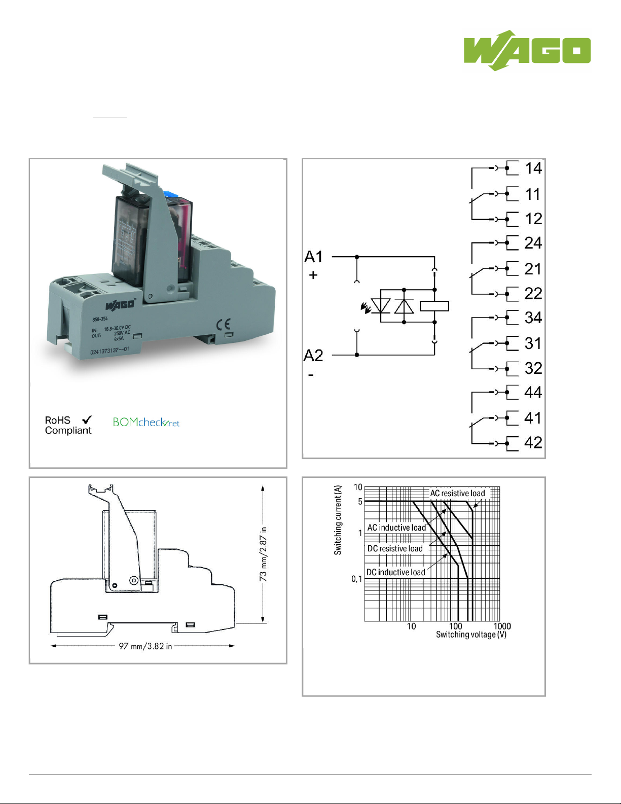
Relay module; Nominal input voltage: 24 VDC; 4 changeover contacts;
Limiting continuous current: 5 A; with manual operation; Path; Red status
indicator; Module width: 31 mm
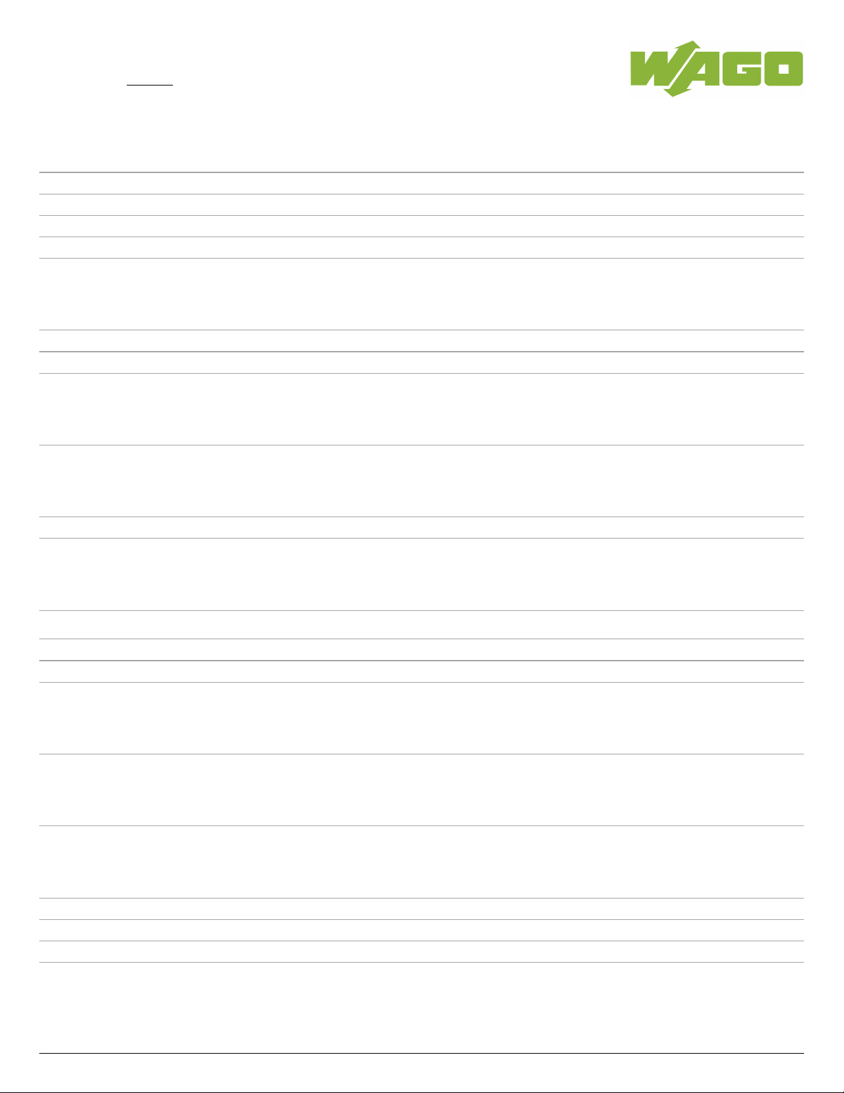
Load limit curve
Item description
Note:
858-354
02.05.2019Page /1 10

Data sheet | Item number:858-354
Inductive loads have to be attenuated by an appropriate protective circuit in order to protect relay coils and contacts.
Data
Technical Data
Control circuit
Nominal input voltage U
N
DC24V
Input voltage range -30 … +25%
Nominal input current at U
N
42mA
Load circuit:
Number of changeover/switchover contacts 4
Contact material (relay) AgCe
Limiting continuous current 5A
Max. make current (resistive) (AC) 15A/ 4s
Max. switching voltage AC250V
Max. switching power (resistive) AC1,000VA;DC see load limit curve
Recommended minimum load 12V/ 100mA
Pull-in time (typ.) 25 ms
Drop-out time (typ.) 25ms
Bounce time (typ) 4 ms
Electrical life (N.O.; resistive load; 23 °C)
100x 10 switching operations
3
Mechanical life (N.O.; resistive load; 23 °C)
20x 10 switching operations
6
Signaling
Status indication LED red
Mechanical
Safety and protection:
Rated voltage 250 V
Rated impulse voltage 2.5 kV
Pollution degree 2
Dielectric strength, control/load circuit (AC, 1 min) 1.5kVrms
Dielectric strength open contact (AC, 1 min) 1kVrms
Dielectric strength, load/load circuit (AC, 1 min) 1.5kVrms
Protection class IP20
858-354
02.05.2019Page /2 10
Data sheet | Item number:858-354
Connection data
Connection technology
Push-in CAGE CLAMP
®
Solid conductor 0.34 … 1.5mm²/ 22 … 16AWG
Fine-stranded conductor 0.34 … 1.5mm²/ 22 … 16AWG
Strip length 9 … 10mm/ 0.35 … 0.39inch
Note (conductor cross-section) 2 x 0.34 … 2 x 1.5 mm² / 1 x 2.5 mm² / 2 x 22 … 2 x 16 AWG
Geometrical Data
Width 31mm/ 1.22inch
Height from upper-edge of DIN-35 rail 73mm/ 2.874inch
Depth 97mm/ 3.819inch
Mechanical data
Type of mounting DIN-35 rail
Material Data
Fire load 0 MJ
Weight 98.3 g
Environmental Requirements
Pollution degree 2
Surrounding air (operating) temperature at U
N
-25 … 70°C
Surrounding air (storage) temperature -40 … 80°C
Processing temperature -25 … +50°C
Standards and specifications
Standards/specifications EN 61010-2-201; EN 61810-1; EN 61373; UL 508
Elementary relay
WAGO elementary relay 858-170
Commercial data
Product Group 6 (Interface Electronics)
Country of origin DE
GTIN 4055143568333
Customs Tariff No. 85364900990
858-354
02.05.2019Page /3 10
 Loading...