

Wago 857-815 Data Sheet
Data sheet | Item number:857-815
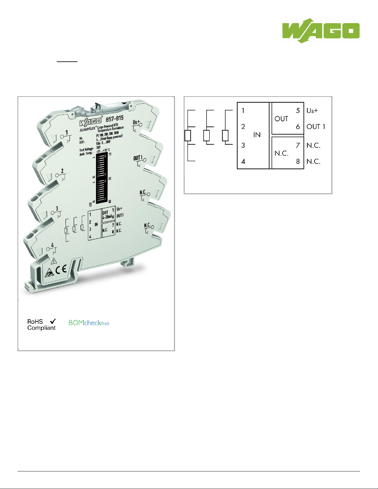
Temperature signal conditioner for RTD sensors; Current and voltage output
signal; Power via output; 6 mm module width
857-815
02.05.2019Page /1 13
Data sheet | Item number:857-815
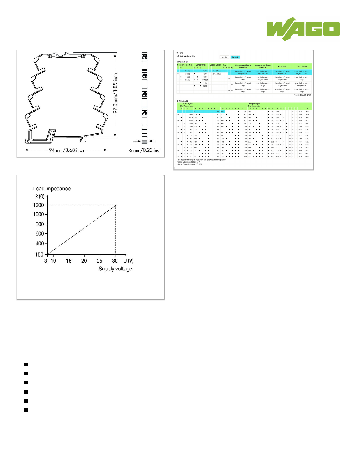
Derating
Item description
Short description:
The 857-815 Loop-Powered RTD Temperature Signal Conditioner records Pt100, Pt200, Pt500 and Pt1000 sensors and resistors up to 4.5 kΩ,
converting the temperature signal into an analog standard signal on the output side.
The loop-powered RTD temperature signal conditioner provides safe isolation between input and output with 3 kV test voltage per EN 61010-1.
Features:
No additional supply voltage required
For Pt100, Pt200, Pt500 and Pt1000 sensors, as well as resistors up to 4.5 kOhm
2-, 3-, and 4-wire connection technology
Switching between measurement ranges is calibrated
Detects sensor wire break/short circuit
Safe 2-way isolation with 3 kV test voltage per EN 61010-1
857-815
02.05.2019Page /2 13

Data sheet | Item number:857-815
Data
Technical Data
Configuration
Configuration options DIP switches
Input
Input signal type Pt sensors
Resistance
Max. input current 50 mA
Max. input voltage 30 V
Input – RTD sensors
Sensor types (RTD) Pt100
Pt200
Pt500
Pt1000
Sensor connection 2-wire; 3-wire; 4-wire (switchable)
Max. sensor supply current (RTD) ≤0.5mA
Measurement range temperature (RTD) -200 … 850°C
Min. measuring span (RTD) 50 K
Input – Resistors
Input range resistance 0 … 1kΩ;0 … 4.5kΩ
Output
Output signal type Current
Output signal voltage 0 … 5 V; 1 … 5 V; 0 … 10 V; 2 … 10 V
Output signal current 0 … 10 mA; 2 … 10 mA; 0 … 20 mA; 4 … 20 mA
Load impedance (output/current) ≤600Ω (See derating graph)
Signal processing
Step response typ. 1,000ms
Measurement error
Transmission error typ. ≤ 0.1 % at max. measuring span
Transmission error of set measurement range ≤ ((40 K/set measurement range [K]) + 0,1) %
Temperature coefficient ≤ 0.02 %/K
857-815
02.05.2019Page /3 13

Data sheet | Item number:857-815
Power supply
Type of power supply loop-powered (via output)
Supply voltage DC8 … 30V (power derived from the output circuit)
Safety and protection:
Test voltage AC 3kV;50Hz;1min
Protection class IP20
Connection data
Connection technology
Push-in CAGE CLAMP
®
Solid conductor 0.08 … 2.5mm²/ 28 … 14AWG
Fine-stranded conductor 0.34 … 2.5mm²/ 22 … 14AWG
Strip length 9 … 10mm/ 0.35 … 0.39inch
Geometrical Data
Width 6mm/ 0.236inch
Height from upper-edge of DIN-35 rail 97.8mm/ 3.85inch
Depth 94mm/ 3.701inch
Mechanical data
Type of mounting DIN-35 rail
Material Data
Fire load 0 MJ
Weight 39.8 g
Environmental Requirements
Surrounding air (operating) temperature -25 … 70°C (at nominal current)
Surrounding air (storage) temperature -40 … 85°C
Relative humidity 5 … 95% (no condensation)
Max. operating altitude 2000 m
Standards and specifications
Conformity marking 1
EMC immunity to interference EN 61000-6-2; EN 61326-1; EN 50121-3-2
EMC emission of interference EN 61000-6-3; EN 61326-1; EN 50121-3-2
Standards/specifications EN 61010-1; EN 61373
857-815
02.05.2019Page /4 13
 Loading...