

Wago 857-364 Data Sheet
Data sheet | Item number:857-364
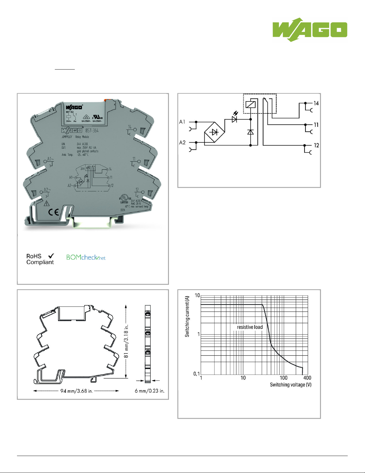
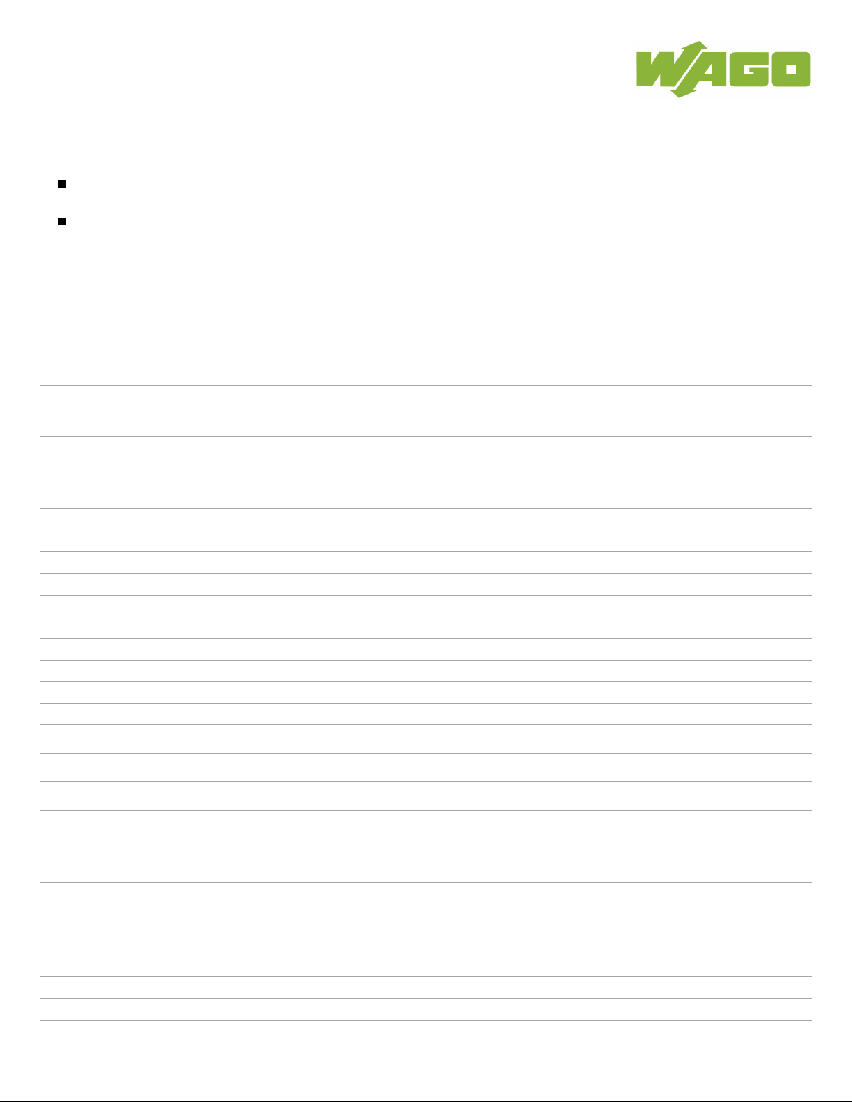
Relay module; Nominal input voltage: 24 V AC/DC; 1 changeover contact;
Limiting continuous current: 6 A; with gold contacts; Yellow status indicator;
Module width: 6 mm
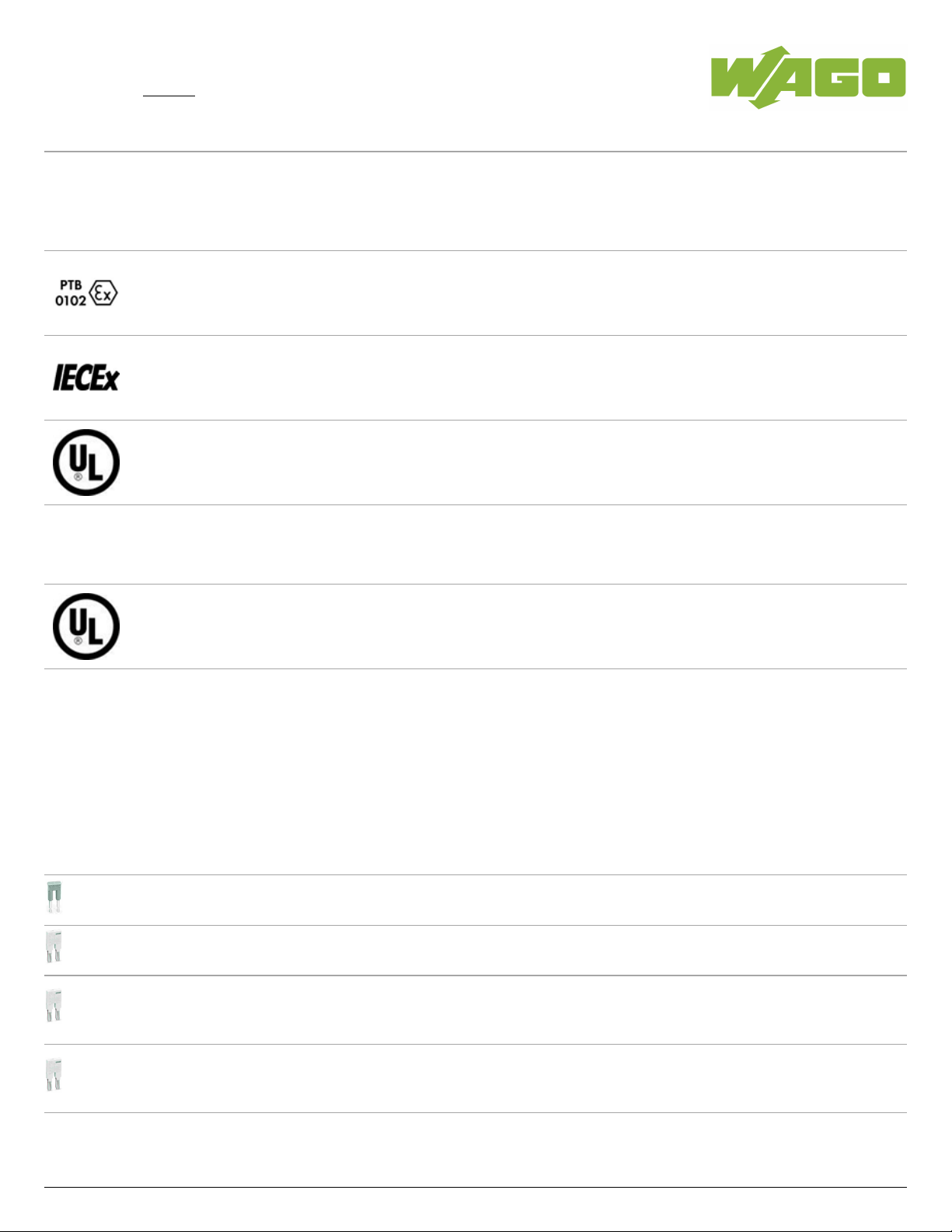
DC load limit curve
Item description
857-364
02.05.2019Page /1 13
Data sheet | Item number:857-364
Note:
To prevent the gold layer from being damaged, 30 VDC switching voltages and 50 mA currents shall not be exceeded. Higher switching
power evaporates the gold layer. The resulting deposits in the housing may reduce the service life.
Inductive loads have to be attenuated by an appropriate protective circuit in order to protect relay coils and contacts.
Data
Technical Data
Control circuit
Nominal input voltage U
N
AC/DC24V
Input voltage range -15 … +20%
Nominal input current at U
N
8.5mA
Load circuit:
Number of changeover/switchover contacts 1
Contact material (relay) AgNi + Au
Limiting continuous current 6A
Max. make current (resistive) (AC) 20A/ 0.02s
Max. switching voltage AC250V
Max. switching power (resistive) AC1,500VA;DC see load limit curve
Switching capacity AC-15:3A/ AC250V;DC-13:2A/ DC24V
Recommended minimum load 1V/ 1mA/ 1mW
Pull-in time (typ.) 15 ms
Drop-out time (typ.) 25ms
Bounce time (typ) 3.5 ms
Electrical life (N.O.; resistive load; 23 °C)
50x 10 switching operations
3
Mechanical life (N.O.; resistive load; 23 °C)
5x 10 switching operations
6
Max. switching load with load/without load
6min / 180min
-1 -1
Signaling
Status indication LED yellow
Safety and protection:
Rated voltage 250 V
Rated impulse voltage 4 kV
Pollution degree 2
Dielectric strength, control/load circuit (AC, 1 min) 4kVrms
857-364
02.05.2019Page /2 13
Data sheet | Item number:857-364
Dielectric strength, control/load circuit (AC, 1 min) 4kVrms
Dielectric strength open contact (AC, 1 min) 1kVrms
Protection class IP20
Connection data
Connection technology
Push-in CAGE CLAMP
®
Solid conductor 0.34 … 2.5mm²/ 22 … 14AWG
Fine-stranded conductor 0.34 … 2.5mm²/ 22 … 14AWG
Strip length 9 … 10mm/ 0.35 … 0.39inch
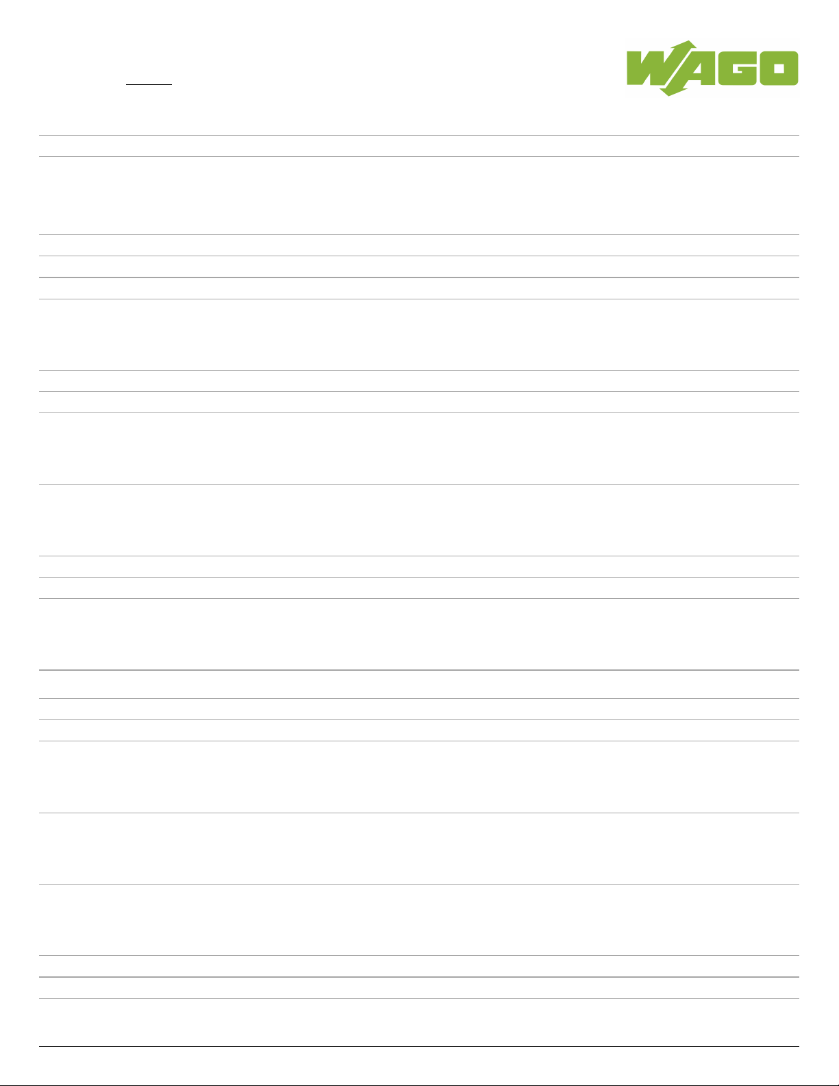
Geometrical Data
Width 6mm/ 0.236inch
Height from upper-edge of DIN-35 rail 81mm/ 3.189inch
Depth 94mm/ 3.701inch
Mechanical data
Type of mounting DIN-35 rail
Material Data
Color gray
Fire load 0 MJ
Weight 30.3 g
Environmental Requirements
Pollution degree 2
Surrounding air (operating) temperature at U
N
-40 … 60°C
Surrounding air (storage) temperature -40 … 70°C
Processing temperature -25 … +50°C
Standards and specifications
Standards/specifications EN 61010-2-201; EN 61810-1; EN 61373; UL 508; ATEX, IEC Ex
Elementary relay
WAGO elementary relay 857-157
Commercial data
Product Group 6 (Interface Electronics)
Country of origin DE
GTIN 4045454673505
857-364
02.05.2019Page /3 13
Data sheet | Item number:857-364
Customs Tariff No. 85364900990
Approvals / Certificates
Ex-Approvals
Logo Approval Additional Approval Text Certificate name
ATEX
DEKRA EXAM GmbH
EN 60079-0 BVS_14_ATEX_E_091_X
IECEx
DEKRA EXAM GmbH
IEC 60079-0 IECEx_BVS_14.0079_X
UL
UL International Germany GmbH (HAZARDOUS
LOCATIONS)
ANSI/ISA 12.12.01 E198726 Sec.4
UL-Approvals
Logo Approval Additional Approval Text
Certificate
name
UL
UL International Netherlands B.V. (ORDINARY
LOCATIONS)
UL 508 E175199
Sec.4
Compatible products
Jumper
Item no.: 281-482
Comb-style jumper bar; insulated; 2-way; IN = IN terminal block
281-482
Item no.: 859-402
Push-in type jumper bar; 2-way; Nominal current 18 A; insulated
859-402
Item no.: 859-402/000-005
Push-in type jumper bar; 2-way; Nominal current 18 A; insulated
859-402
/000-005
Item no.: 859-402/000-006
Push-in type jumper bar; 2-way; Nominal current 18 A; insulated
859-402
/000-006
857-364
02.05.2019Page /4 13
 Loading...