

Page 1
Pos: 2 /Dokumentation allgemein/Einband/Einband Dec kblatt @ 9\mod_1285229289866_0.doc @ 64941 @ @ 1
Manual
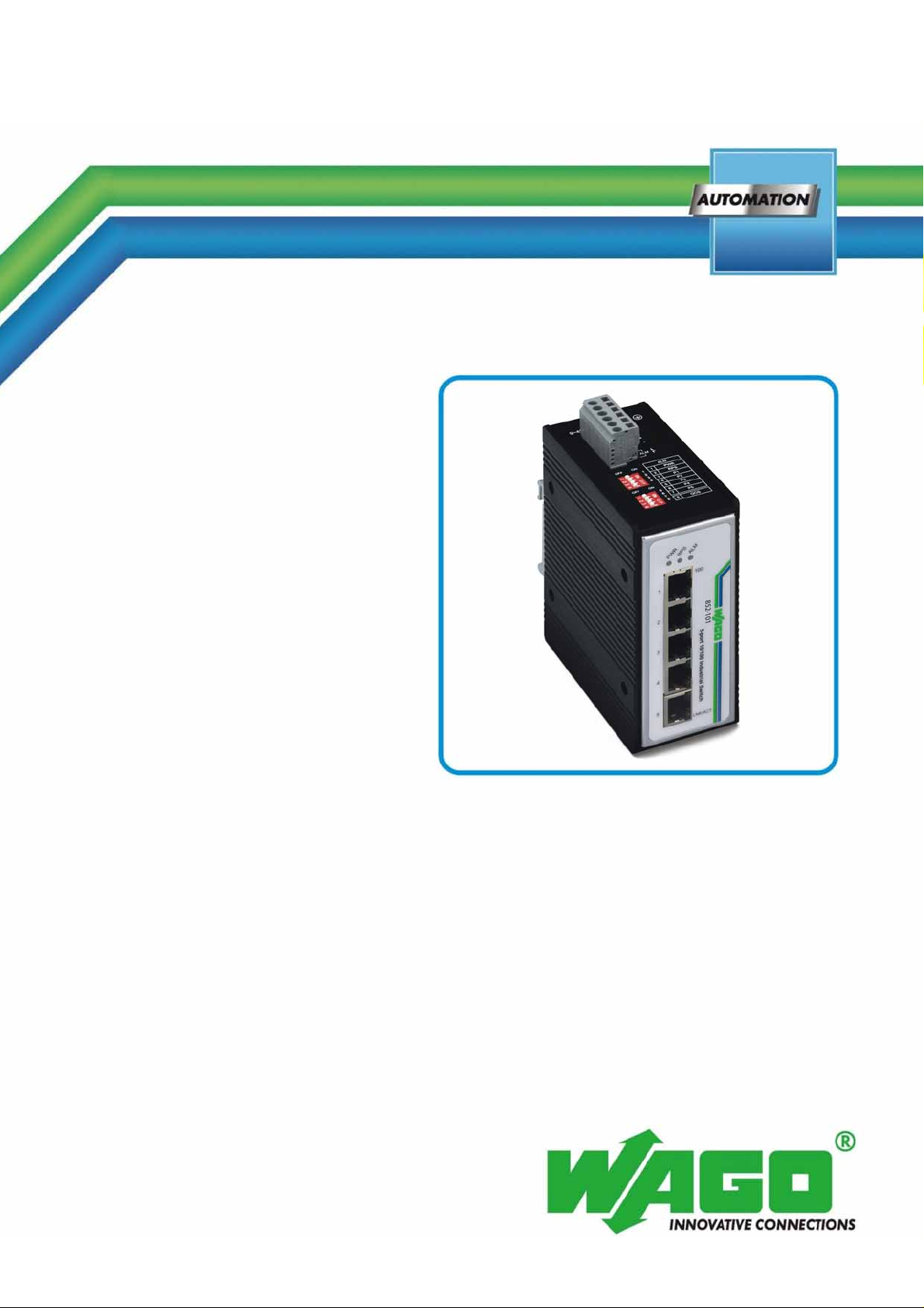
WAGO ETHERNET Accessories 852
5-Port 100BASE-TX Industrial Switch
852-101
Assembly, Installation and Handling
Version 1.0.2
Pos: 3 /Alle Serien (Allgemeine Module)/Hinweise zur Doku mentation/Impressum - allgemeine Angaben, Anschr iften, Telefonnummern und E-Mail-Adressen @ 3\mod_12 19151118203_21.doc @ 21060 @ @ 1
Page 2

2 WAGO ETHERNET Accessories 852
852-101 5-Port 100BASE-TX Industrial Switch
© 2011 by WAGO Kontakttechnik GmbH & Co. KG
All rights reserved.
WAGO Kontakttechnik GmbH & Co. KG
Hansastraße 27
D-32423 Minden
Phone: +49 (0) 571/8 87 – 0
Fax: +49 (0) 571/8 87 – 1 69
E-Mail: [email protected]
Web: http://www.wago.com
=== Ende der Liste für Textmarke Einband_vorne ===
Technical Support
Phone: +49 (0) 571/8 87 – 5 55
Fax: +49 (0) 571/8 87 – 85 55
E-Mail: [email protected]
Every conceivable measure has been taken to ensure the accuracy and
completeness of this documentation. However, as errors can never be fully
excluded, we always appreciate any information or suggestions for improving the
documentation.
E-Mail: [email protected]
We wish to point out that the software and hardware terms as well as the
trademarks of companies used and/or mentioned in the present manual are
generally protected by trademark or patent.
Manual
Version 1.0.2
Page 3

WAGO ETHERNET Accessories 852 Table of Contents 3
852-101 5-Port 100BASE-TX Industrial Switch
Pos: 5 /Dokumentation allgemein/Verzeichnisse/ I nhaltsverzeichnis - ohne Gliederung - und Verzeichnis @ 3\ mod_1219151230875_21.doc @ 21063 @ @ 1
Table of Contents
1 Important Notes........................................................................................... 4
1.1 Legal Bases ...............................................................................................4
1.1.1 Subject to Changes............................................................................... 4
1.1.2 Personnel Qualification........................................................................ 4
1.1.3 Proper Use of the Industrial Switches.................................................. 4
1.1.4 Technical Condition of Specified Devices........................................... 4
1.2 Standards and Regulations for Operating the Industrial Switches............ 5
1.3 Symbols..................................................................................................... 6
1.4 Safety
1.5 Font
1.6 Number Notation....................................................................................... 9
2 General........................................................................................................ 10
2.1 Package Contents.................................................................................... 10
2.2
Industrial Ethernet Technology............................................................... 10
2.3 Switching
2.4 Auto Negotiation..................................................................................... 12
2.5 Switching, Filtering................................................................................. 12
2.6 Port Speed & Duplex Mode.................................................................... 12
Information ....................................................................................8
Conventions...................................................................................... 9
Technology ............................................................................11
3 Hardware Description ...............................................................................13
3.1 Connectors............................................................................................... 13
3.1.1 10/100BASE-TX Ports....................................................................... 13
3.2 Views....................................................................................................... 14
3.2.1 Front View of Industrial Switch......................................................... 14
3.2.2 TOP View of Industrial Switch.......................................................... 15
3.2.3 Back View of Industrial Switch .........................................................16
3.3 Display elements..................................................................................... 17
3.3.1 Unit LED´s .........................................................................................17
3.3.2 Port LED´S......................................................................................... 18
3.4 Operating elements.................................................................................. 19
3.5 Connection
3.5.1
Power Input (PWR/RPS).................................................................... 20
elements............................................................................... 20
4 Assembly..................................................................................................... 21
5 Installation.................................................................................................. 21
5.1 DIN Rail Mounting................................................................................. 21
6 Technical Data............................................................................................23
7 Appendix..................................................................................................... 24
7.1 Appendix A............................................................................................. 24
7.1.1 RJ-45 Cables....................................................................................... 24
List of Figures......................................................................................................25
List of Tables........................................................................................................ 26
=== Ende der Liste für Textmarke Verzeichnis_vorne ===
Manual
Version 1.0.2
Page 4

4 Important Notes WAGO ETHERNET Accessories 852
852-101 5-Port 100BASE-TX Industrial Switch
Pos: 7.1 /Alle Serien (Allgemeine Module)/Überschr iften für alle Serien/Wichtige Erläuterungen - Übersc hrift 1 @ 4\mod_1241428899156_21.doc @ 32170 @ 1 @ 1
1 Important Notes
Pos: 7.2 /Alle Serien (Allgemeine Module)/Wic hti ge E r läuterungen/Einleitung Wichtige Erläuterungen @ 3\ mod _122 1059818031_21.doc @ 21717 @ @ 1
This section includes an overall summary of the most important safety
requirements and notes that are mentioned in each individual section. To protect
your health and prevent damage to devices as well, it is imperative to read and
carefully follow the safety guidelines.
Pos: 7.3 /Alle Serien (Allgemeine Module)/Überschr iften für alle Serien/Rechtliche Grundlagen - Übersc hr ift 2 @ 3\mod_1221060626343_21.doc @ 21726 @ 2 @ 1
1.1 Legal Bases
Pos: 7.4 /Alle Serien (Allgemeine Module)/Wic hti ge E r läuterungen/Änderungsvorbehalt @ 3\mod_1221060036 484_ 21.doc @ 21720 @ 3 @ 1
1.1.1 Subject to Changes
WAGO Kontakttechnik GmbH & Co. KG reserves the right to provide for any
alterations or modifications that serve to increase the efficiency of technical
progress. WAGO Kontakttechnik GmbH & Co. KG owns all rights arising from
the granting of patents or from the legal protection of utility patents. Third-party
products are always mentioned without any reference to patent rights. Thus, the
existence of such rights cannot be excluded.
Pos: 7.5 /Serie 852 (Ethernet-Zubehör)/Wichtige Er läuterungen/Personalqualifikation @ 3\mod_12223 46340968_21.doc @ 22264 @ 3 @ 1
1.1.2 Personnel Qualification
All sequences implemented on Series 852 devices may only be carried out by
electrical specialists with sufficient knowledge in automation. The specialists
must be familiar with the current norms and guidelines for the devices and
automated environments.
All changes to the controller should always be carried out by qualified personnel
with sufficient sufficient skills in PLC programming.
Pos: 7.6 /Serie 852 (Ethernet-Zubehör)/Wichtige Er läuterungen/Bestimmungsgemäße Verwendung @ 3\mod_1222 346110578_21.doc @ 22258 @ 3 @ 1
1.1.3 Proper Use of the Industrial Switches
The device is designed for the IP30 protection class. It is protected against the
insertion of solid items and solid impurities up to 2.5 mm in diameter, but not
against water penetration. Unless otherwise specified, the device must not be
operated in wet and dusty environments.
Pos: 7.7 /Alle Serien (Allgemeine Module)/Wic hti ge E r läuterungen/Technischer Zustand der Geräte @ 3\mod_1221060 446109_21.doc @ 21723 @ 3 @ 1
1.1.4 Technical Condition of Specified Devices
The components to be supplied Ex Works, are equipped with hardware and
software configurations, which meet the individual application requirements.
WAGO Kontakttechnik GmbH & Co. KG will be exempted from any liability in
case of changes in hardware or software as well as to non-compliant usage of
components.
Please send your request for modified and new hardware or software
configurations directly to WAGO Kontakttechnik GmbH & Co. KG.
Pos: 7.8 /Serie 852 (Ethernet-Zubehör)/Wichtige Er läuterungen/Normen und Richtlinien @ 3\mod_12223462394 53_21.doc @ 22261 @ 2 @ 1
Manual
Version 1.0.2
Page 5

WAGO ETHERNET Accessories 852 Important Notes 5
852-101 5-Port 100BASE-TX Industrial Switch
1.2 Standards and Regulations for Operating the Industrial Switches
Please observe the standards and regulations that are relevant to installation:
• The data and power lines must be connected and installed in compliance
with the standards to avoid failures on your installation and eliminate any
danger to personnel.
• For installation, startup, maintenance a nd repair, please observe the accident
prevention regulations of your machine (e.g., BGV A 3, "Electrical
Installations and Equipment").
• Emergency stop functions and equipment must not be deactivated or
otherwise made ineffective. See relevant standards (e.g., DIN EN 418).
• Your installation must be equipped in accordance to the EMC guidelines so
electromagnetic interferences can be eliminated.
Pos: 7.9 /Dokumentation allgemein/Gliederungse lemente/---Seitenwechsel--- @ 3\mod_1221108045078_0.doc @ 21810 @ @ 1
• Please observe the safety measures against electrostatic discharge according
to DIN EN 61340-5-1/-3. When handling the modules, ensure that
environmental factors (persons, workplace and packing) are well grounded.
• The relevant valid and applicable standards and guidelines regarding the
installation of switch cabinets must be observed.
Manual
Version 1.0.2
Page 6
6 Important Notes WAGO ETHERNET Accessories 852
852-101 5-Port 100BASE-TX Industrial Switch
Pos: 7.10 /Alle Serien (Allgemeine Module)/Hinweise zur Dokumentation/Symbole @ 3\mod_1217394197593_21. doc @ 21010 @ 2 @ 1
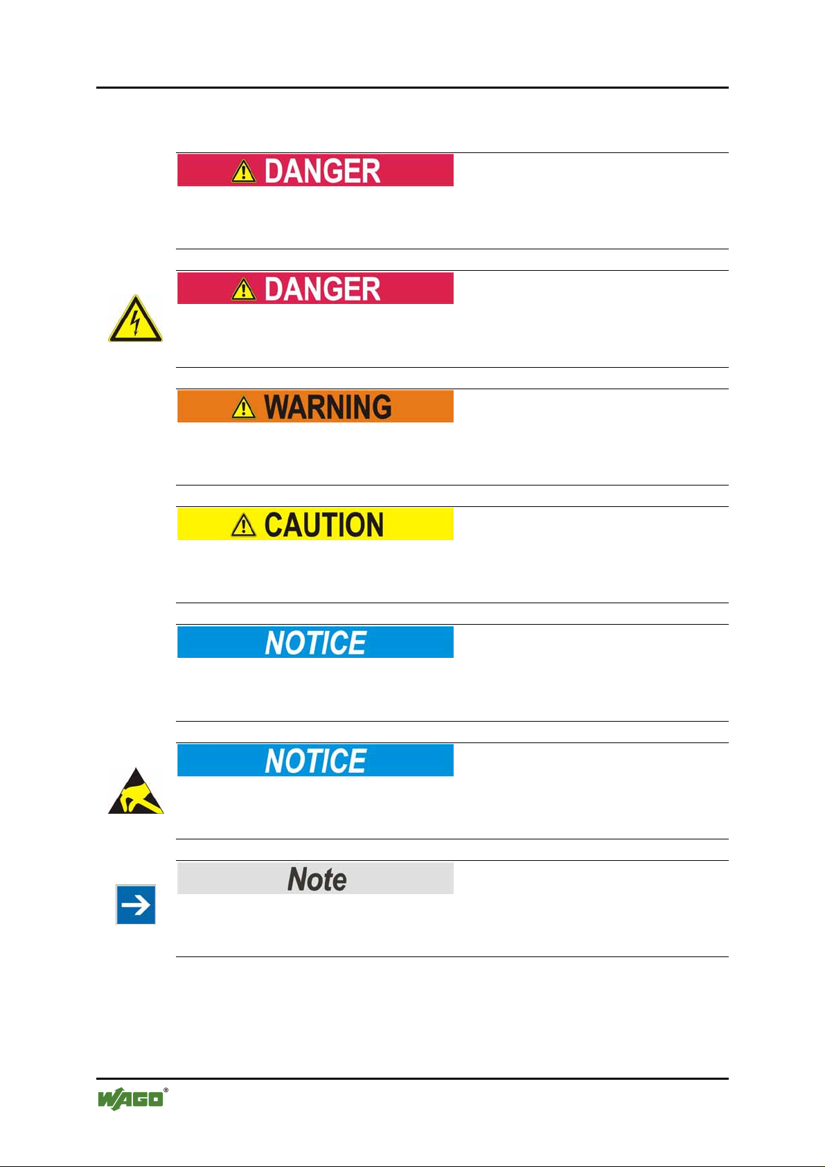
1.3 Symbols
Personal Injury!
Indicates a high-risk, imminently hazardous situation which, if not avoided, will
result in death or serious injury.
Personal Injury Caused by Electric Current!
Indicates a high-risk, imminently hazardous situation which, if not avoided, will
result in death or serious injury.
Personal Injury!
Indicates a moderate-risk, potentially hazardous situation which, if not avoided,
could result in death or serious injury.
Personal Injury!
Indicates a low-risk, potentially hazardous situation which, if not avoided, may
result in minor or moderate injury.
Damage to Property!
Indicates a potentially hazardous situation which, if not avoided, may result in
damage to property.
Damage to Property Caused by Electrostatic Discharge (ESD)!
Indicates a potentially hazardous situation which, if not avoided, may result in
damage to property.
Important Note!
Indicates a potential malfunction which, if not avoided, however, will not result in
damage to property.
Manual
Version 1.0.2
Page 7

WAGO ETHERNET Accessories 852 Important Notes 7
852-101 5-Port 100BASE-TX Industrial Switch
Additional Information:
Refers to additional information which is not an integral part of this
documentation (e.g., the Internet).
Pos: 7.11 /Dokumentation allgemein/Gliederungse lemente/---Seitenwechsel--- @ 3\mod_1221108045078_0.doc @ 21810 @ @ 1
Manual
Version 1.0.2
Page 8
8 Important Notes WAGO ETHERNET Accessories 852
852-101 5-Port 100BASE-TX Industrial Switch
Pos: 7.12 /Serie 852 (Ethernet-Zubehör)/Wic hti ge Erläuterungen/Sicherheitshinweise 852-101, 102 @ 3\ mod_1222346469359_21.doc @ 22267 @ 2 @ 1
1.4 Safety Information
Warning of physical injury
Industrial Switches are exposed operating equipment. They may only be
assembled in housings, cabinets or in electrical operation rooms. Access is only
permitted via a key or tool to authorized qualified personnel.
Warning of physical injury
All power sources to the device must always be switched off before performing
any installation, repair or maintenance work.
Warning of damage to equipment
The components are not resistant against materials having seeping and insulating
properties such as: aerosols, silicones, triglycerides (found in some hand creams).
If it cannot be determined that these materials appear in the component
environment, then the components must be installed in an enclosure that is
resistant against the above mentioned materials. Clean tools and materials are
generally required to operate the device/module.
Warning of damage to equipment
Soiled contacts must be cleaned using oil-free compressed air or with ethyl
alcohol and leather cloths.
Warning of damage to equipment
Do not use contact sprays, which could possibly impair contact area functionality.
Warning of damage to equipment
Avoid reverse polarity of data and power lines as this may damage the devices.
Warning of damage to equipment
This is a Class A product. In a domestic environment this product may cause
radio interference in which case the user may be required to take adequate
measures.
Manual
Version 1.0.2
Page 9
WAGO ETHERNET Accessories 852 Important Notes 9
852-101 5-Port 100BASE-TX Industrial Switch
Warning of damage to equipment by electrostatic discharge
The devices are equipped with electronic components that may be destroyed by
electrostatic discharge when touched.
Pos: 7.13 /Alle Serien (Allgemeine Module)/Hinweise zur Dokumentation/Schriftkonventionen @ 3\mod_12210 59521437_21.doc @ 21714 @ 2 @ 1
1.5 Font Conventions
Table 1: Font Conventions
Font type Indicates
Names of paths and data files are marked in italic-type.
e.g.: C:\Programme\WAGO-I/O-CHECK
Menu items are marked in bold letters.
e.g.: Save
A greater-than sign between two names means the selection of a
menu item from a menu.
e.g.: File > New
Designation of input or optional fields are marked in bold letters,
e.g.: Start of measurement range
e.g.: Enter the value “4 mA” under Start of measurement range.
Pushbuttons in dialog boxes are marked with bold letters in square
brackets.
e.g.: [Input]
Keys are marked with bold letters in square brackets.
e.g.: [F5]
Pos: 7.14 /Alle Serien (Allgemeine Module)/Hinweise zur Dokumentation/Zahlensysteme @ 3\mod_1221059454 015_ 21.doc @ 21711 @ 2 @ 1
italic
Menu
>
Input
“Value” Input or selective values are marked in inverted commas.
[Button]
[Key]
1.6 Number Notation
Table 2: Number Notation
Number code Example Note
Decimal 100 Normal notation
Hexadecimal 0x64 C notation
Binary '100'
'0110.0100'
Pos: 8 /Dokumentation allgemein/Gliederungsele mente/---Seitenwechsel--- @ 3\mod_1221108045078_0.doc @ 21810 @ @ 1
Manual
Version 1.0.2
In quotation marks, nibble separated with
dots (.)
Page 10

10 General WAGO ETHERNET Accessories 852
852-101 5-Port 100BASE-TX Industrial Switch
Pos: 9.1 /Serie 852 (Ethernet-Zubehör)/Einleitu ng/ Einleitung @ 3\mod_1222676076609_21.doc @ 22308 @ 1 @ 1
2 General
Pos: 9.2 /Serie 852 (Ethernet-Zubehör)/Einleitu ng/ Paketinhalt 852-101, 102, 103 @ 3\mod_1222683414218_2 1. doc @ 22314 @ 2 @ 1
2.1 Package Contents
• One Industrial Switch
• DIN rail bracket
• Protective caps for unused ports
Pos: 9.3 /Serie 852 (Ethernet-Zubehör)/Einleitu ng/ Industrielle Ethernet Technologie @ 3\mod_1222680431 062_21.doc @ 22311 @ 2 @ 1
2.2 Industrial Ethernet Technology
The line of switches from WAGO ensure the scalability of your network
infrastructure with outstanding electrical and mechanical characteristics. These
robust devices are designed for industrial use and they are fully compliant with
IEEE802.3, 802.3u.
They have function monitoring and redundant voltage supply with a supply
voltage range of 9 … 48 V. Alarm functions are enabled via DIP switch.
Characteristics such as auto negotiation and auto MDI/MDIX (crossover) on all
10/100 BaseTX ports are also realized, as is a store-and-forward switching mode.
Pos: 9.4 /Dokumentation allgemein/Gliederungse lemente/---Seitenwechsel--- @ 3\mod_1221108045078_0.doc @ 21810 @ @ 1
Manual
Version 1.0.2
Page 11

WAGO ETHERNET Accessories 852 General 11
852-101 5-Port 100BASE-TX Industrial Switch
Pos: 9.5 /Serie 852 (Ethernet-Zubehör)/Einleitu ng/ Switch Technologie @ 3\mod_1222683606296_21.doc @ 22317 @ 2 @ 1
2.3 Switching Technology
Another approach to pushing beyond the limits of Ethernet technology is the
development of switching technology. A switch bridge Ethernet packets at the
MAC address level of the Ethernet protocol transmitting among connected
Ethernet or Fast Ethernet LAN segments.
Switching is a cost-effective way of increasing the total network capacity
available to users on a local area network. A switch increases capacity and
decreases network loading by dividing a local area network into different
segments, which don’t compete with each other for network transmission
capacity.
Pos: 9.6 /Serie 852 (Ethernet-Zubehör)/Gerätebeschr eibung/Eigenschaften allgemein @ 3\mod_1220960 1042 03_21.doc @ 21260 @ @ 1
The Industrial Switch was designed for easy installation in an industrial
environment where vibration, shock, heat, and RF interference may be
commonplace.
The Industrial Switch, with its small, compact size, was specifically designed for
easy DIN rail mounting and can be installed where space is limited.
Pos: 9.7 /Dokumentation allgemein/Gliederungse lemente/---Seitenwechsel--- @ 3\mod_1221108045078_0.doc @ 21810 @ @ 1
The Industrial Switch is ideal for deployment with multiple high-speed servers for
shared bandwidth 10 Mbps or 100 Mbps workgroups. With the highest bandwidth
200 Mbps (100 Mbps full duplex mode), any port can provide workstations with a
congestion-free data pipe for simultaneous access to the server.
The Industrial Switch is expandable by cascading two or more switches together
in a ‘daisy-chain’ fashion. As all ports support 200 Mbps, the Industrial Switch
can be cascaded from any port and to any number of switches.
The Industrial Switch combines dynamic memory allocation with store-and
forward switching to ensure that the buffer is effectively allocated for each port,
while controlling the data flow between the transmit and receive nodes to
guarantee against all possible packet loss.
Manual
Version 1.0.2
Page 12

12 General WAGO ETHERNET Accessories 852
852-101 5-Port 100BASE-TX Industrial Switch
Pos: 9.8 /Serie 852 (Ethernet-Zubehör)/Gerätebeschr eibung/Eigenschaften 852-101 @ 3\mod_12209643892 34_21.doc @ 21267 @ @ 1
Other key features are:
• Five (5) 10/100Base-TX ports
• Rugged metal-IP30 case
• Vibration/Shock operational
• Wide voltage range: 9 … 48 V
• DIP switch to enable or disable alarm functions
• Power input polarity protection function
• Wide operating temperature 0 °C … +60 °C
• Auto negotiation at all copper ports
Pos: 9.9 /Serie 852 (Ethernet-Zubehör)/Einleitu ng/ Auto Negotiation @ 3\mod_1222427670250_21.doc @ 22290 @ 2 @ 1
2.4 Auto Negotiation
The Industrial Switch’s 10/100Mbps switched RJ-45 ports auto negotiates with
connected devices to determine the fastest data transmission rate supported by
both devices. This helps make the Switch a plug and play device. The Switch’s
RJ-45 ports support full or half duplex, depending on which transmission speed is
supported by the attached device.
Pos: 9.10 /Serie 852 (Ethernet-Zubehör)/Einleit ung/ Switching, Filtern @ 3\mod_1222427760578_21.doc @ 22298 @ 2 @ 1
2.5 Switching, Filtering
Packets entering the Industrial Switch with source and destination addresses
belonging to the same port segment will be filtered, limiting those packets to one
port, and relieving the rest of the network from the need to process them. A packet
with a destination address served by another port segment will be forwarded to the
appropriate port, and will not be sent to the other ports where it is not needed.
Packets that are used to maintain network operations (such as the occasional multi
cast packet) are forwarded to all ports.
The Industrial Switch operates in the store and forward switching mode, which
eliminates bad packets and enables peak performance to be achieved when there is
heavy traffic on the network.
Pos: 9.11 /Serie 852 (Ethernet-Zubehör)/Einleit ung/ Port-Geschwindigkeit und Duplex-Modus @ 3\mod_1222 427724921_21.doc @ 22294 @ 2 @ 1
2.6 Port Speed & Duplex Mode
After a cable is plugged into a specific port, the system uses auto negotiation to
determine the transmission mode for the new twisted pair connection:
If the connected device does not support auto negotiation or has auto negotiation
disabled, an auto sensing process is initiated to select the speed and set the duplex
mode to half duplex.
Pos: 10 /Dokumentation allgemein/Gliederungsele mente/---Seitenwechsel--- @ 3\mod_1221108045078_0.doc @ 21810 @ @ 1
Manual
Version 1.0.2
Page 13

WAGO ETHERNET Accessories 852 Hardware Description 13
852-101 5-Port 100BASE-TX Industrial Switch
Pos: 11.1 /Serie 852 (Ethernet-Zubehör)/Gerätebesc hreibung/Hardwarebeschreibung 852-101 @ 3\mod_1221 051098750_21.doc @ 21660 @ 1 @ 1
3 Hardware Description
The 852-101 Industrial Switch is a 5 port 10/100Base-TX Ethernet switch. The
switch has a rugged housing, a redundant power supply and function monitoring
with relay, making it ideal for a wide range of applications.
Pos: 11.2 /Serie 852 (Ethernet-Zubehör)/Gerätebesc hreibung/Anschlüsse 852-101, 102 @ 3\mod_122166249543 7_21.doc @ 21878 @ 23 @ 1
3.1 Connectors
3.1.1 10/100BASE-TX Ports
The 10/100BASE-TX ports support network speeds of either 10 Mbps or
100 Mbps, and can operate in half- and full-duplex transfer modes. The ports also
offer automatic MDI/MDI-X crossover detection that gives true “plug and play”
capability – just plug the network cables into the ports and the ports will adjust
according to the end-node devices. The following are the recommended cables for
the RJ-45 connectors:
• 10M – Cat 3 or better / 100M – Cat 5 or better
Pos: 11.3 /Dokumentation allgemein/Gliederungse lemente/---Seitenwechsel--- @ 3\mod_1221108045078_0.doc @ 21810 @ @ 1
Manual
Version 1.0.2
Page 14
14 Hardware Description WAGO ETHERNET Accessories 852
852-101 5-Port 100BASE-TX Industrial Switch
Pos: 11.4 /Serie 852 (Ethernet-Zubehör)/Gerätebesc hreibung/Ansichten 852-101 @ 3\mod_1221730227265_21. doc @ 21888 @ 2333 @ 1
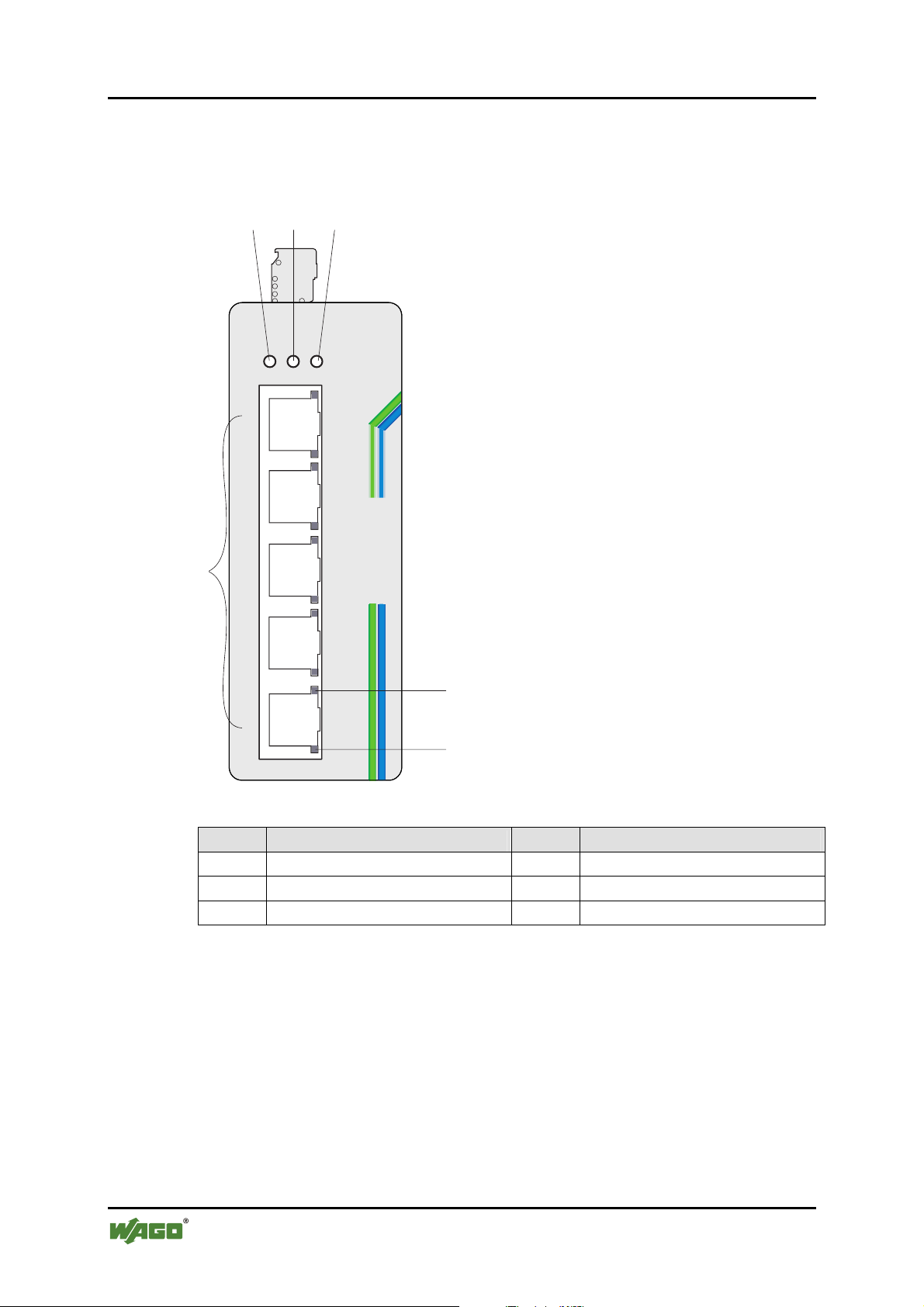
3.2 Views
3.2.1 Front View of Industrial Switch
123
RPS
ALM
100
PWR
1
852-101
2
5-port 10/100 Industrial Switch
6
3
4
5
LNK/ACT
Figure 1: Front view of switch
4
5
Pos. Description Pos. Description
1 Primary Power LED 2 Redundant Power LED
3 Alarm LED 4 TX port 100 Mbps LED
5 TX port LNK/ACT LED 6 TX ports (5)
Manual
Version 1.0.2
Page 15
WAGO ETHERNET Accessories 852 Hardware Description 15
852-101 5-Port 100BASE-TX Industrial Switch
3.2.2 TOP View of Industrial Switch
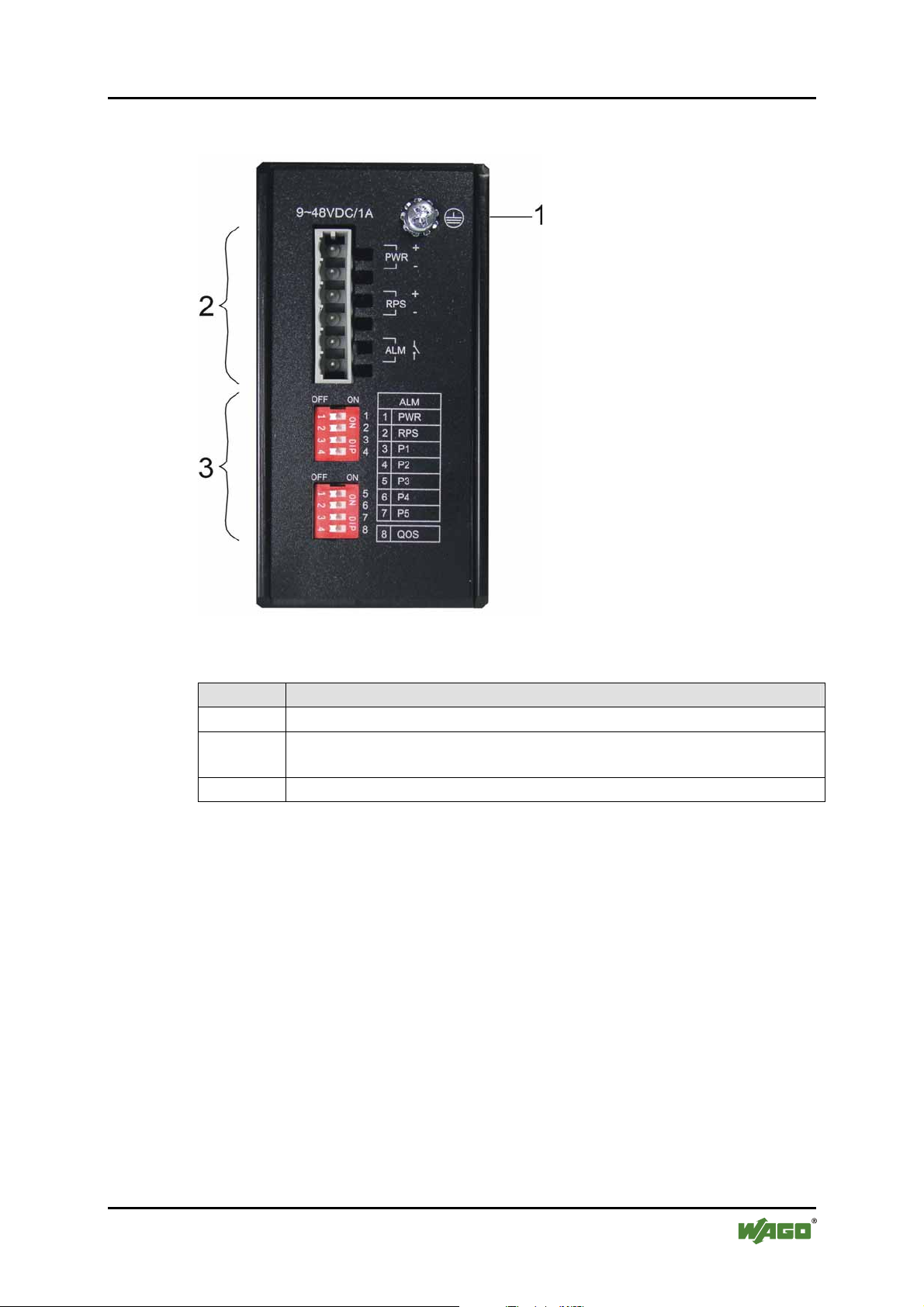
Figure 2: Top view of switch
Position Description
1 Grounding Screw
2 Terminal block (male connector) for power input (PWR/RPS) and
alarm dry contact
3 DIP switches
Manual
Version 1.0.2
Page 16
16 Hardware Description WAGO ETHERNET Accessories 852
852-101 5-Port 100BASE-TX Industrial Switch
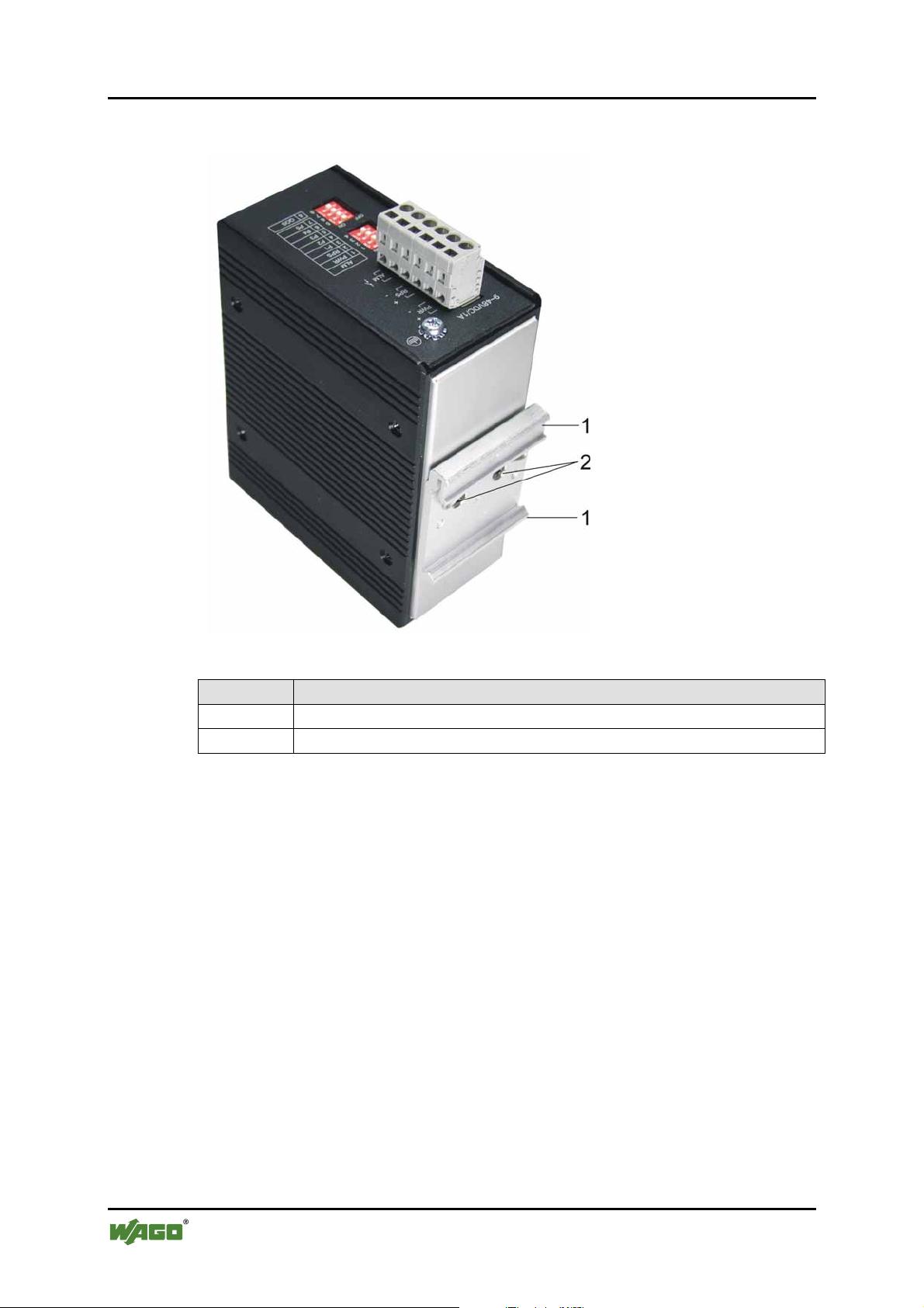
3.2.3 Back View of Industrial Switch
Pos: 11.5 /Dokumentation allgemein/Gliederungse lemente/---Seitenwechsel--- @ 3\mod_1221108045078_0.doc @ 21810 @ @ 1
Figure 3: Back view of switch
Position Description
1 Din Rail Bracket
2 Screws
Manual
Version 1.0.2
Page 17
WAGO ETHERNET Accessories 852 Hardware Description 17
852-101 5-Port 100BASE-TX Industrial Switch
Pos: 11.6 /Serie 852 (Ethernet-Zubehör)/Gerätebesc hreibung/LED-Anzeigen 852-101 @ 3\mod_12217454548 59_21.doc @ 21924 @ 233 @ 1
3.3 Display elements
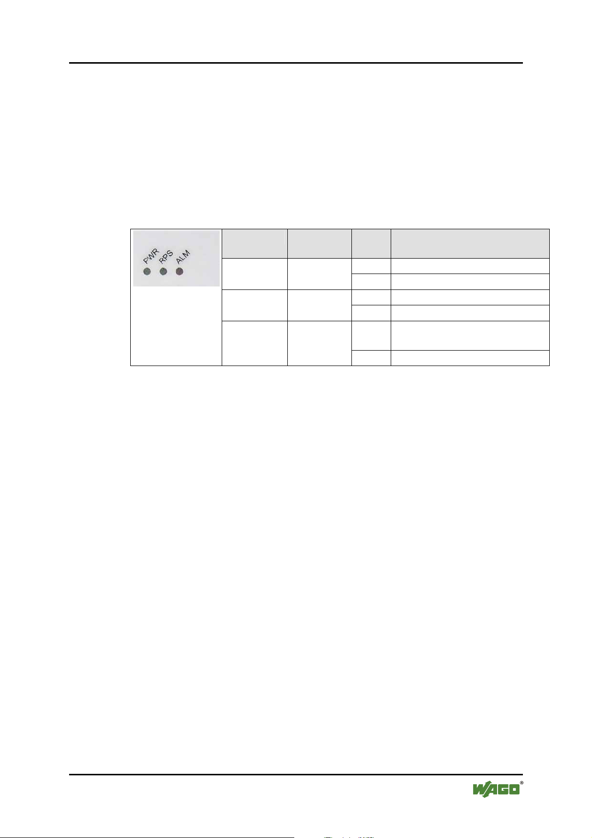
This Industrial Switch is equipped with Unit LEDs to enable you to quickly
determine the status of the Switch, as well as Port LEDs to see what is happening
across your connection.
They are as follows:
3.3.1 Unit LED´s
Table 3: Unit LED´s
Figure 4: Unit LED´s
LED Desig-
nation
Power LED
Power LED
ALM Alarm LED
Status Description
Green Switch uses primary power PWR Primary
Off Primary power off or failure
Green Switch uses redundant power RPS Redundant
Off Redundant power off failure
Red Illuminated when power fails
or link fails
Off No alarm to report
Manual
Version 1.0.2
Page 18
18 Hardware Description WAGO ETHERNET Accessories 852
852-101 5-Port 100BASE-TX Industrial Switch
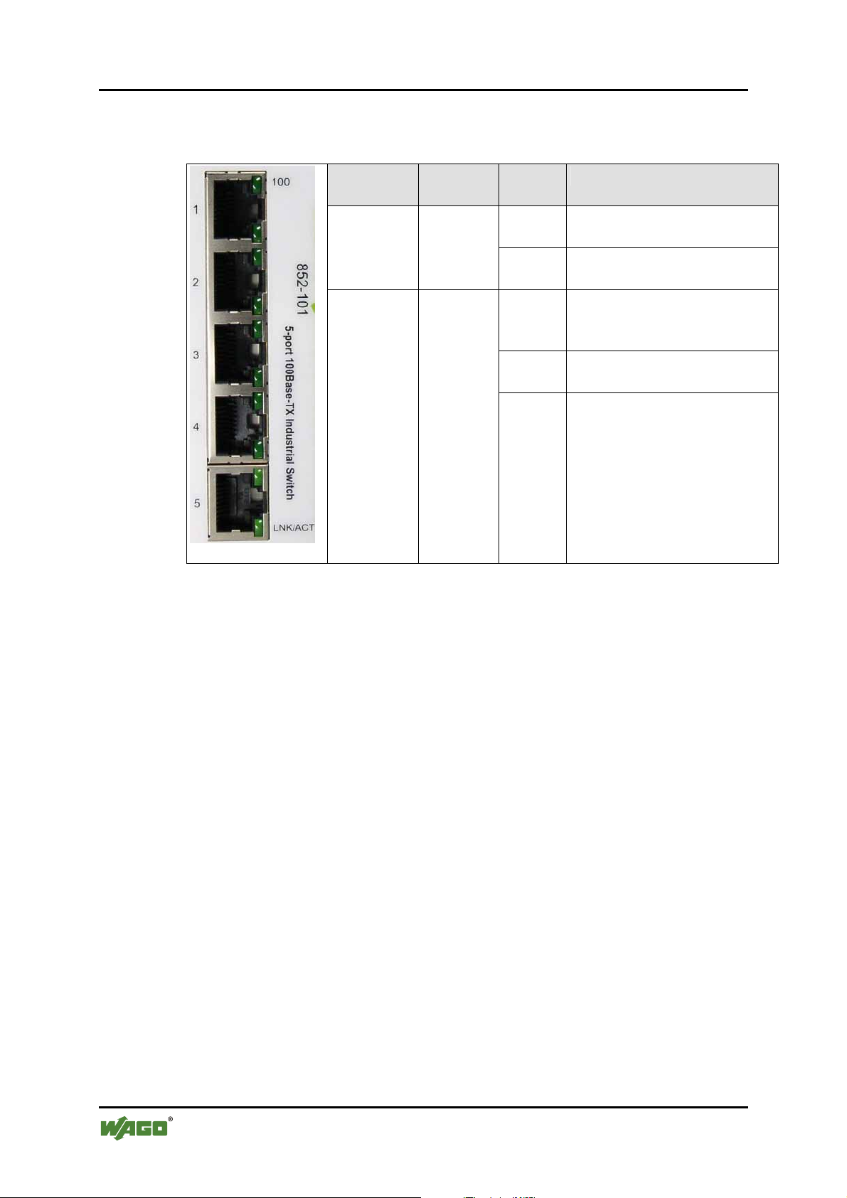
3.3.2 Port LED´S
Table 4: Port LED´s
LED Desig-
nation
100 TX-port
100 Mbps
LED
LNK/ACT TX port
LNK/
ACT
LED
Status Description
Green Port operating at 100 Mps (1
LED for each port)
Off Port operating at below
100 Mps
Green Illuminated when connectors
are attached (1 LED for each
port)
Flashing
Data traffic passing through
port
Off No valid link established on
port
Pos: 11.7 /Dokumentation allgemein/Gliederungse lemente/---Seitenwechsel--- @ 3\mod_1221108045078_0.doc @ 21810 @ @ 1
Figure 5: Port LED´s
Manual
Version 1.0.2
Page 19
WAGO ETHERNET Accessories 852 Hardware Description 19
852-101 5-Port 100BASE-TX Industrial Switch
Pos: 11.8 /Serie 852 (Ethernet-Zubehör)/Gerätebesc hreibung/Bedienelemente 852-101 @ 3\mod_12217456523 43_21.doc @ 21927 @ 2 @ 1
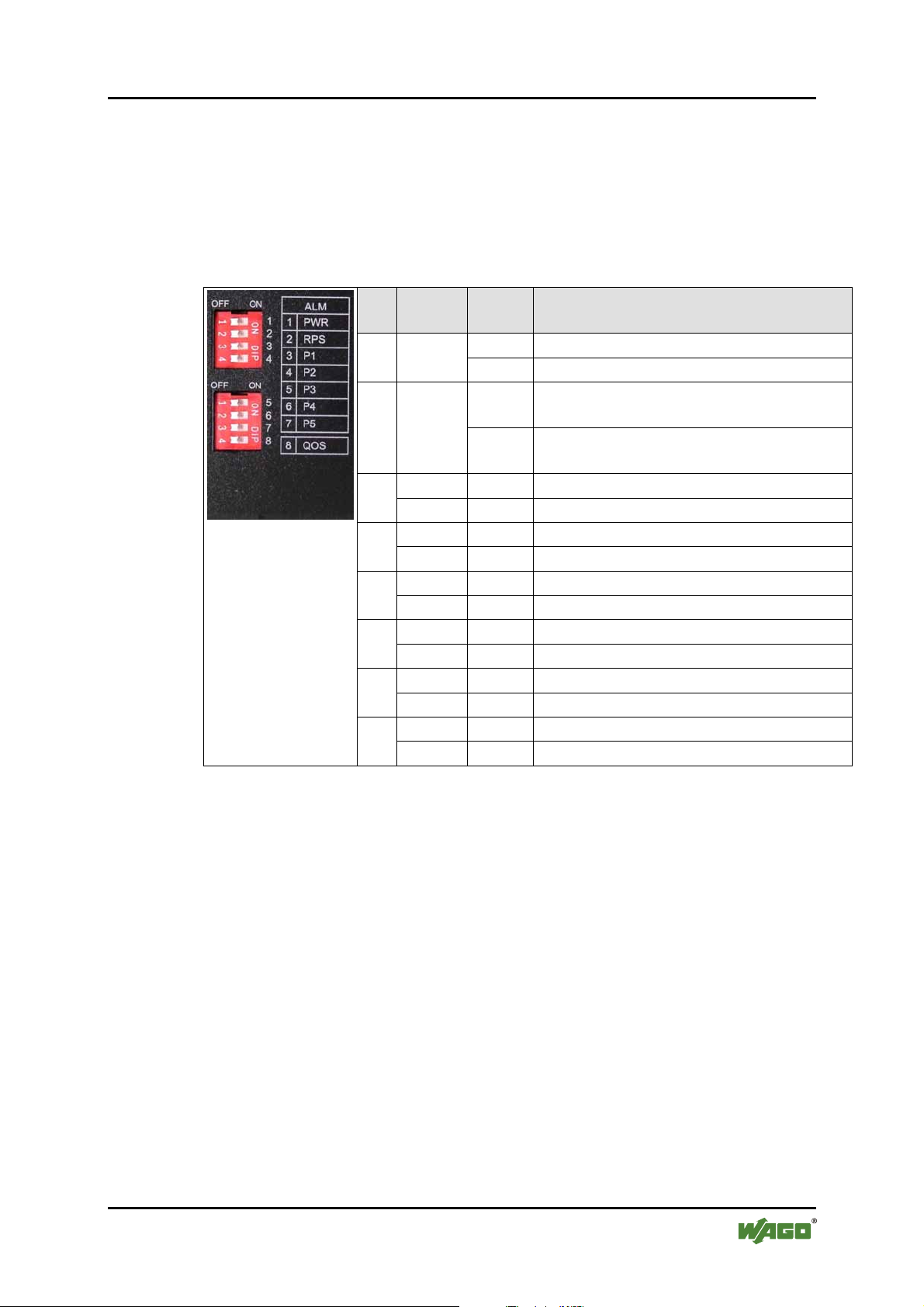
3.4 Operating elements
On the top side of the Industrial Switch there are DIP switches to configure the
alarm and arbiter configurations.
The meaning of the DIP switch settings are described below:
Table 5: Operating elements
Figure 6: Operating
elements
No. Desig-
nation
2 RPS
P1 ON Port 1 link alarm reporting is enabled 3
OFF Port 1 link alarm reporting is enabled
P2 ON Port 2 link alarm reporting is enabled 4
OFF Port 2 link alarm reporting is disabled
P3 ON Port 3 link alarm reporting is enabled 5
OFF Port 3 link alarm reporting is disabled
P4 ON Port 4 link alarm reporting is enabled 6
OFF Port 4 link alarm reporting is disabled
P5 ON Port 5 link alarm reporting is enabled 7
OFF Port 5 link alarm reporting is disabled
QoS ON QoS function on Port 1 is enabled
8
OFF QoS function on Port 1 is disabled
State Function
ON Master power alarm reporting is enabled 1 PWR
OFF Master power alarm reporting is disabled
ON Redundant power alarm reporting is
enabled
OFF Redundant power alarm reporting is
disabled
DIP-switches let the user manually turn “ON/OFF” any port, the external Alarm,
or the redundant power supply.
DIP-switch to the “ON” position to manually enable the alarm function for the
port. Default is “OFF”.
The following is the Recommended Procedure for configuring and setting DIPswitches during initial installation:
1 Turn all DIP-switches “OFF”.
2 Install the Industrial Switch into your network.
3 Decide which port(s) need to be monitored or should trigger the alarm.
4 Turn the corresponding port DIP-switch “ON”.
5 Activate the Industrial Switch.
Pos: 11.9 /Dokumentation allgemein/Gliederungse lemente/---Seitenwechsel--- @ 3\mod_1221108045078_0.doc @ 21810 @ @ 1
Manual
Version 1.0.2
Page 20
20 Hardware Description WAGO ETHERNET Accessories 852
852-101 5-Port 100BASE-TX Industrial Switch
Pos: 11.10 /Serie 852 (Ethernet-Zubehör)/Gerätebesc hreibung/Anschlusselemente @ 3\mod_122769847 9625 _21.doc @ 25299 @ 2 @ 1
3.5 Connection elements
Pos: 11.11 /Serie 852 (Ethernet-Zubehör)/Gerätebesc hreibung/Spannungsversorgung @ 3\mod_12217458 7442 1_21.doc @ 21930 @ 3 @ 1
3.5.1 Power Input (PWR/RPS)
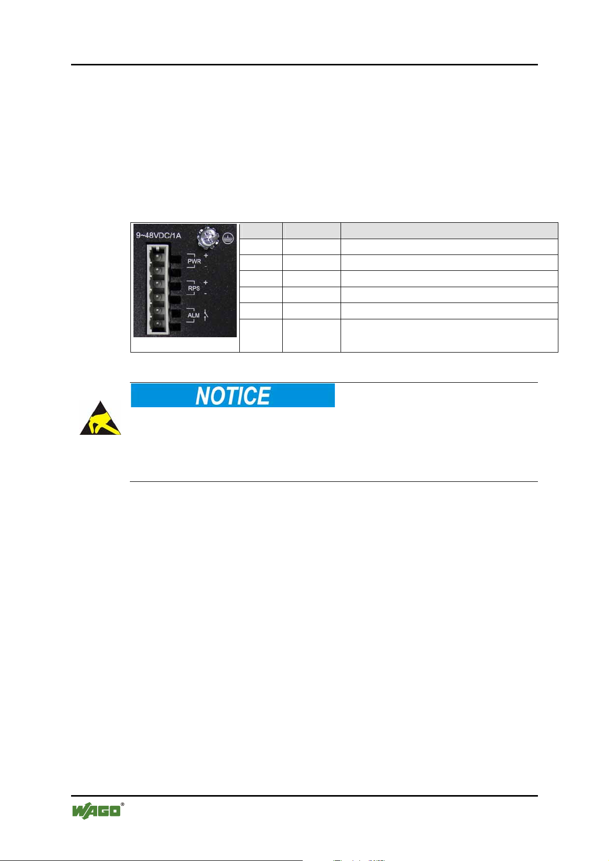
The female connector can easily be connected to the 6-pole male connector
located on the top of the switch.
The male connector shows the following pin assignment:
Table 6: Power Input (PWR/RPS)
Name Designation
+ PWR Primary DC input
- PWR Primary DC input
+ RPS Redundant DC input
- RPS Redundant DC input
ALM Contact for external alarm
ALM Contact for external alarm
Figure 7: Power Input
Pos: 12 /Dokumentation allgemein/Gliederungsele mente/---Seitenwechsel--- @ 3\mod_1221108045078_0.doc @ 21810 @ @ 1
Warning of damage to equipment by electrostatic discharge
DC Powered Switch: Power is supplied through an external DC power source.
Check the technical specification section for information about the DC power
input voltage. Since the switch does not include a power switch, plugging its
power adapter into a power outlet will immediately power it on.
Manual
Version 1.0.2
Page 21
WAGO ETHERNET Accessories 852 Assembly 21
852-101 5-Port 100BASE-TX Industrial Switch
Pos: 13.1 /Alle Serien (Allgemeine Module)/Überschr iften für alle Serien/Montieren - Überschrift 1 @ 3\ mod_1225446744750_21.doc @ 24900 @ 1 @ 1
4 Assembly
Pos: 13.2 /Serie 852 (Ethernet-Zubehör)/Montieren/ Montageort 852-101, 102 @ 3\mod_1227782803203_21.doc @ 25309 @ 1 @ 1
5 Installation
The location selected to install the Industrial Switch may greatly affect its
performance. When selecting a site, we recommend considering the following
rules:
• Install the Industrial Switch at an appropriate place. See in chapter
“Technical Data” for the acceptable temperature and humidity operating
ranges.
• Fix the provided brackets at the back of the Industrial Switch to a DIN rail
to protect the switch from falling.
Pos: 13.3 /Serie 852 (Ethernet-Zubehör)/Montieren/ Montieren auf Tragschiene @ 3\mod_1222422141203_21. doc @ 22278 @ 2 @ 1
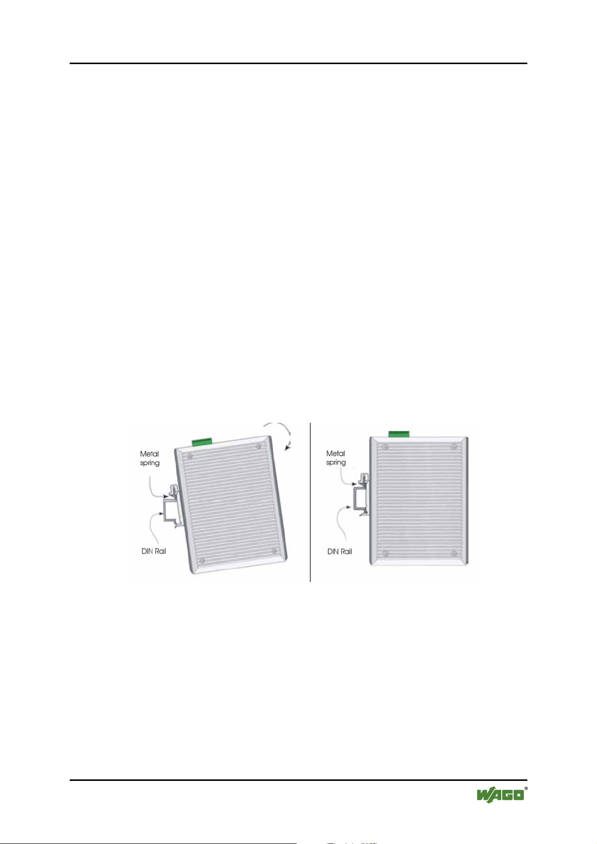
5.1 DIN Rail Mounting
The aluminum DIN Rail attachment plate should already be affixed to the back
panel of the Industrial Switch. If you need to attach the DIN Rail plate, assure that
the stiff metal spring is situated towards the top. Attaching the Industrial Switch to
the DIN rail is easy, just align, and attach the top rail, then press down and snap
forward the Industrial Switch to snap in the bottom rail, as shown in the figures
below.
Figure 8: DIN Rail Mounting
The setup of the Industrial Switch can be performed using the following steps:
• The surface must support at least 1.5 kg for the Industrial Switch.
• Visually inspect th e DC power jack and make sure that it is fully secured to
the power adapter.
• Make sure that there is proper heat dissipation from and adequate ventilation
around the Industrial Switch. Do not place heavy objects on the Industrial
Switch.
Manual
Version 1.0.2
Page 22

22 Installation WAGO ETHERNET Accessories 852
852-101 5-Port 100BASE-TX Industrial Switch
• The carrier rail must optimally support the EMC measures integrated into
the system and the shielding of the internal data bus connections.
Important note
Grounding Industrial Switch will help eliminate the effects of noise due to
electromagnetic interference (EMI). Always run the ground connection from the
ground screw to the grounding surface prior to connecting DC power.
Pos: 14 /Dokumentation allgemein/Gliederungsele mente/---Seitenwechsel--- @ 3\mod_1221108045078_0.doc @ 21810 @ @ 1
Manual
Version 1.0.2
Page 23

WAGO ETHERNET Accessories 852 Technical Data 23
852-101 5-Port 100BASE-TX Industrial Switch
Pos: 15 /Serie 852 (Ethernet-Zubehör)/Technische Da ten/Technische Daten 852-101 @ 3\mod_1221048870937_21. doc @ 21508 @ 1 @ 1
6 Technical Data
Table 7: Technical Data
Technical Data
Ports 5 x 10/100Base-TX (RJ-45)
Standards IEEE 802.3u 100Base-TX;
IEEE 802.3 10Base-T
Maximum distances 10/100Base-TX: 100 m
Supply voltage DC 9 V … 48 V (line length < 3 m)
Power consumtion max. 3.84 W
Power consumption typ. (24 V) 3.36 W
Operating temperature 0 °C ... +60 °C
Storage temperature -20 °C ... +80 °C
Relative air humidity (no condensation) 95 %
Dimensions (mm) W x H x L 50 x 105 x 120
Height from upper edge of DIN 35 rail
Weight approx. 639 g
Vibration resistance acc. to IEC60068-2-6
Shock resistance acc. to IEC60068-2-27
Degree of protection IP 30
EMC-Immunity to Interference acc. to EN 61000-6-2 (2005)
EMC-Emission of Interference acc. to EN 61000-6-4 (2007)
Pos: 16 /Dokumentation allgemein/Gliederungsele mente/---Seitenwechsel--- @ 3\mod_1221108045078_0.doc @ 21810 @ @ 1
Manual
Version 1.0.2
Page 24
24 Appendix WAGO ETHERNET Accessories 852
852-101 5-Port 100BASE-TX Industrial Switch
Pos: 17.1 /Alle Serien (Allgemeine Module)/Überschr iften für alle Serien/Anhang - Überschrift 1 @ 4\mod_123987 4070437_21.doc @ 30560 @ 1 @ 1
7 Appendix
Pos: 17.2 /Serie 852 (Ethernet-Zubehör)/Anhang/An hang A 85 2-101,102,103 @ 3\mod_1222691500859_21.doc @ 22334 @ 23 @ 1
7.1 Appendix A
7.1.1 RJ-45 Cables
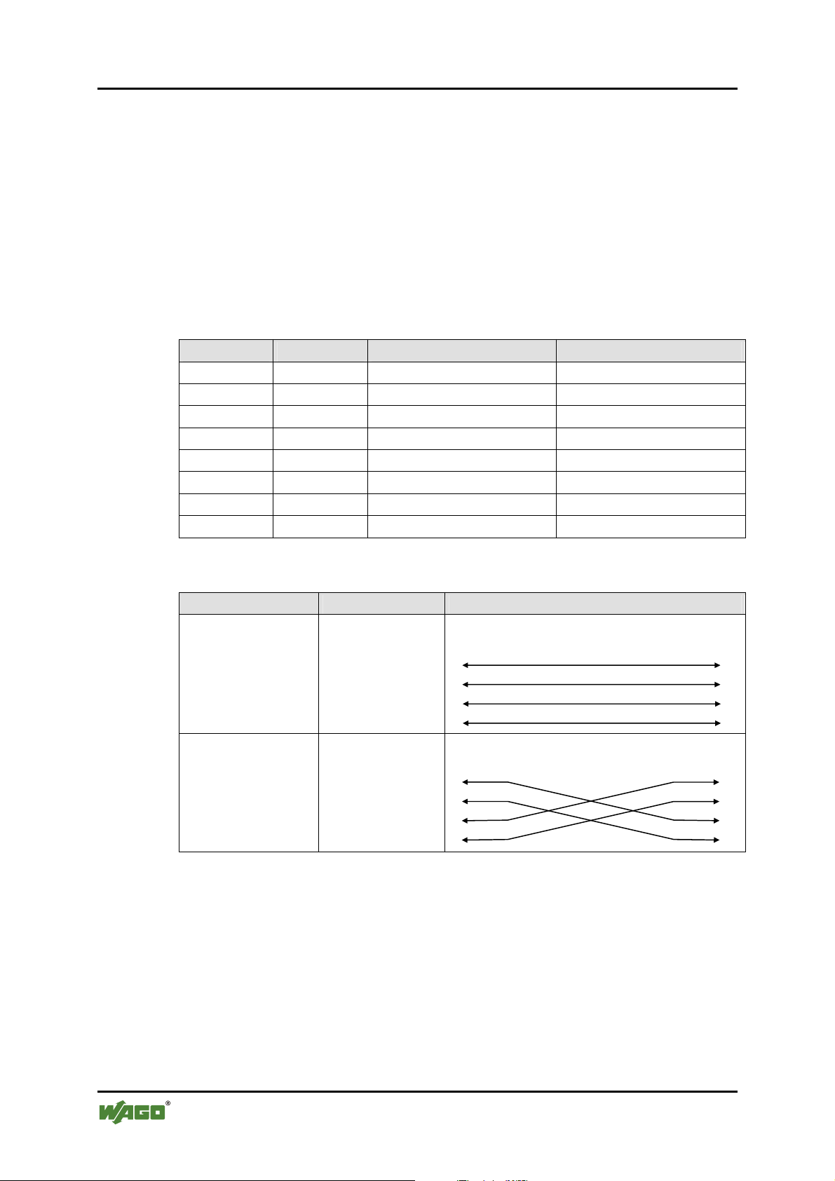
When connecting your network devices, use a standard Category 3 eight way
cable for a 10Base-T configuration and a Category 5 cable for 100Base-TX. The
pin assignments are as follows:
Table 8: RJ-45 Cables
Pin Pair Colours
1 TD+ Pair 2 White/Orange
2 TD- Pair 2 Orange/White
3 RX+ Pair 3 White/Green
4 N/A Pair 1 Blue/White
5 N/A Pair 1 White/Blue
6 RX- Pair 3 Green/White
7 N/A Pair 4 Brown/White
8 N/A Pair 4 Brown/White
=== Ende der Liste für Textmarke Inhalt_mitte ===
Table 9: Configuration
Application Cable Type Application
Switch
to
Switch
or
Network Adapter
Straight through
Cable
Switch Hub
End
1 1
2 2
3 3
6 6
Switch Converter
Converter
to
Switch
Cross Over
Cable
End #1 End #2
1 1
2 2
3 3
6 6
Remark
The Switch features automatic MDI/MDI-X and NWay on RJ-45 port.
Manual
Version 1.0.2
Page 25

WAGO ETHERNET Accessories 852 List of Figures 25
852-101 5-Port 100BASE-TX Industrial Switch
Pos: 19 /Dokumentation allgemein/Verzeichnisse/ Abbi ldungsverzeichnis - ohne Gliederung - und Verzeic hni s @ 3\mod_1219222916765_21.doc @ 21080 @ @ 1
List of Figures
Figure 1: Front view of switch..............................................................................14
Figure 2: Top view of switch ................................................................................15
Figure 3: Back view of switch............................................................................... 16
Figure 1: Unit LED´s............................................................................................. 17
Figure 2: Port LED´s.............................................................................................18
Figure 1: Operating elements................................................................................19
Figure 1: Power Input............................................................................................20
Figure 1: DIN Rail Mounting................................................................................21
Pos: 20 /Dokumentation allgemein/Gliederungsele mente/---Seitenwechsel--- @ 3\mod_1221108045078_0.doc @ 21810 @ @ 1
Manual
Version 1.0.2
Page 26

26 List of Tables WAGO ETHERNET Accessories 852
852-101 5-Port 100BASE-TX Industrial Switch
Pos: 21 /Dokumentation allgemein/Verzeichnisse/ Tabellenverzeichnis - ohne Gliederung - und Verzeic hnis @ 3\mod_1219222958703_21.doc @ 21084 @ @ 1
List of Tables
Table 1: Font Conventions......................................................................................9
Table 1: Number Notation....................................................................................... 9
Table 1: Unit LED´s..............................................................................................17
Table 2: Port LED´s ..............................................................................................18
Table 1: Operating elements..................................................................................19
Table 1: Power Input (PWR/RPS).........................................................................20
Table 1: Technical Data ........................................................................................23
Table 1: RJ-45 Cables ........................................................................................... 24
Table 2: Configuration .......................................................................................... 24
=== Ende der Liste für Textmarke Verzeichnis_hinten ===
Manual
Version 1.0.2
Page 27

WAGO ETHERNET Accessories 852 27
852-101 5-Port 100BASE-TX Industrial Switch
Pos: 23 /Dokumentation allgemein/Einband/Einband Le erseite für gerade Seitenzahl @ 3\mod_1219230851078_0. doc @ 21123 @ @ 1
Manual
Version 1.0.2
Page 28

Pos: 24 /Dokumentation allgemein/Einband/Einband Rückseite @ 9\mod_1285229376516_21.doc @ 64944 @ @ 1
WAGO Kontakttechnik GmbH & Co. KG
Postfach 2880 • D-32385 Minden
Hansastraße 27 • D-32423 Minden
Phone: +49/5 71/8 87 – 0
Fax: +49/5 71/8 87 – 1 69
E-Mail: [email protected]
Internet: http://www.wago.com
=== Ende der Liste für Textmarke Einband_hinten ===
 Loading...