

Page 1
Mounting - and Installation Instructions 789-601 / 789-602 incl. Versions /xxx- xxx
Page 1
Mounting and Installation Instructions
789-601 4 Channel Radio Receiver with
Normally Open Contacts;
230V~ / 16A
789-602 4 Channel Radio Receiver with
Change Over Contacts;
230V~ / 8A
Features
•Radio Receiver for Battery and Wireless Sensors
•Status indication via LED
•868 MHz Frequency band
•Transmitter / Receiver assignment via Learn-Mode
•4 potentialfree contacts
•Invertable Outputs; Switch or Toggle beviour selectable
•Supply voltage 24V DC
•External Antenna for optimized Transmission Range (always
required)
•CAGE-CLAMP®terminals
1. General Description
The Radio Receivers in the modular installation housing is
designed for switching of 4 individual loads (e.g. lamps) via
radio sensors and push-buttons which are based on Enocean
Radio Technology. Transmission is on a european-wide
harmonized transmission band of 868 MHz. The system is
specially dedicated for flexible, pluggable building or industrial
automation because the expenditure for new or reconfiguring of
installations is minimized.
Compatibility: The Radio Receiver is compatible to wireless
sensors of different manufacturers. The sensors must be based
on EnOcean PTM or STM transmitters (see chapter 8.3).
Transmitter - Receiver - Assignment: One receiver could be
operated from up to 40 transmitters, each channel from up to 10
transmitters. The assignment between sensor and output has to
be teached once during commissioning, the assignments are
stored mains-failure protected in the NV-Ram of the Receiver.
Mixed operation of PTM and STM Modules is possible. One
sensor could be assigned to multiple outputs (1:n); multiple
transmitters could be assigned to one output channel (n:1).
Output Contacts: Loads are operated via 4 relays with
normally-open or change over contacts. The max. permissible
load per contact is either 8A (789-602) or 16A (789-601).
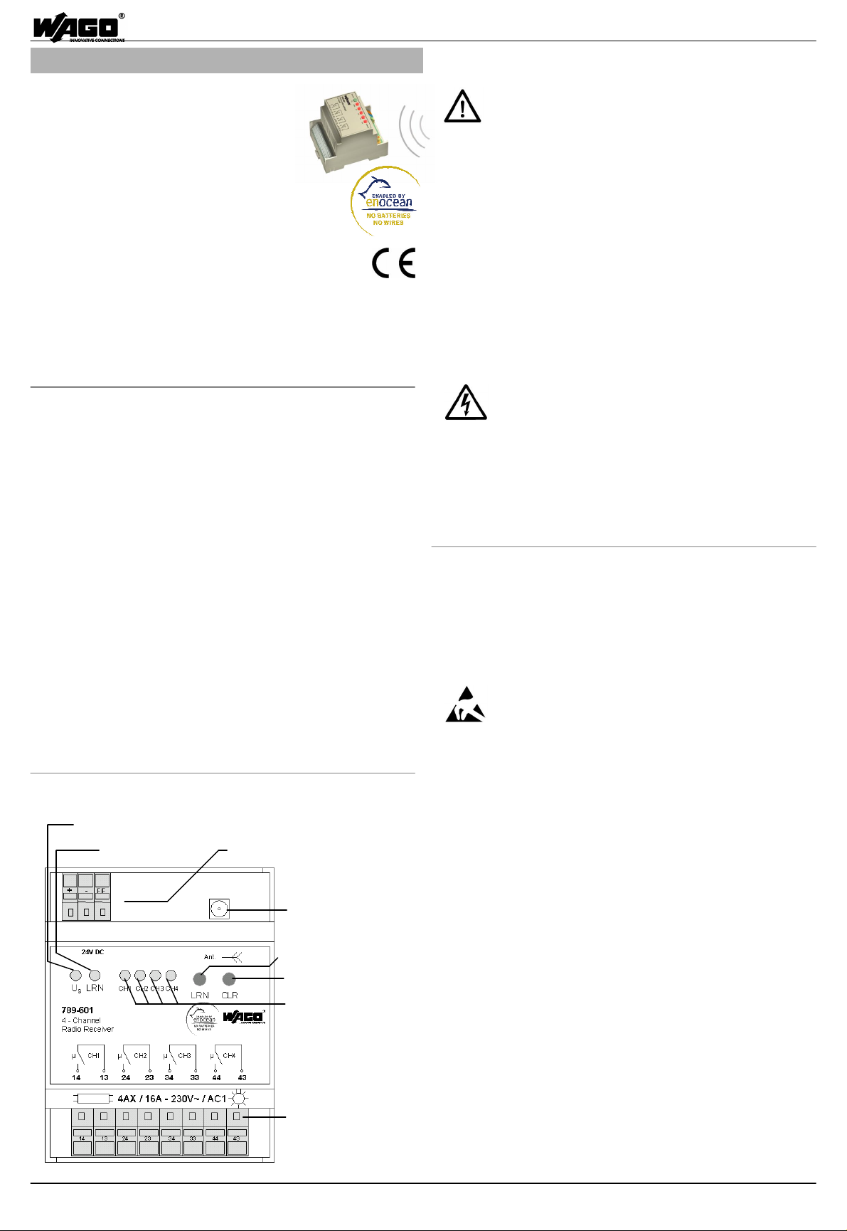
2. Front-View and Operating Elements
LED-indication
Supply voltage
LED-Indicator
Learn-Mode
Terminals for
int. voltage supply
3. Restrictions and Regulations
3.1 Legal Regulations
The following topics should be observed:
- the valid laws, norms and regulations
- the applicable local codes in respect to wiring practices
- the state of the technology at time of installation
- the operating manual from sensors and receiver
- the general rules of the technique
- the fact, that instructions manuals could only inform about
general regulations and these have to correspond with plant or
local regulations.
3.1 Restrictions for the Operation of Radio Transmitters or
Receivers
The use of the devices does not need to be registered and is
free in the European Union, Switzerland, Cyprus, the Czech
Republic, Poland and in Slovenia.
The use in other countries requires explicit clarification!
4. Advice for Safety
! Danger for Life existing in case of open
unit by electrical power !
Electrical connection, mounting and dismounting is
only allowed by qualified electrical personal.
Switch Off mains/power connectors before mounting or
dismounting of the Radio Receiver.
Observe assignment of the connectors.
Wrong wiring may destroy the device or lead to short circuits.
Failure to observe these precautions could result in severe
bodily injury or loss of life.
5. Commissioning
Before commissioning the receiver should be proofed for
mechanical- or transport-damages. In case of probable
damages the commissioning of the unit is not allowed.
Read the instruction manual carefully and observe the technical
advices and applying legal regulations.
5.1 Handling Advices / ESD (Electrostatic Discharge)
The modules are equipped with electronic
components that may be destroyed by electrostatic
discharge. When handling the modules, ensure
that the environment (persons, workplace and packing) is well
grounded. Avoid touching of conductive components.
5.2. General Advices for Installation
Avoid installing the module, the antenna and the antenna line
close to sources of transient interferences, such as fluorescent
tubes with defective starter, frequency converters and power
cables. As a result, communication failures may occur leading
to faulty output behavior.
5.3 Advices for Antenna Installation
SMA-Antennajack
Use only appropriate antenna (WAGO 758-910 incl. 2.5 m
RG174-cable and SMA-connector; see accessories).
Antenna must be mounted on metal footer with min. dimensions
Learn (LRN)-Button
of 25 cm x 25 cm.
Antenna including cable must have min 30 cm distance to
Clear (CLR)-Button
Status indication of
outputs 1...4
interference sources and antenna should have free space to
walls of min. 35 cm.
The cable must not be bended because the cable may be
damaged (RG174 bending radius > 15 mm).
5.4 Preconditions for Commissioning
Before commissioning the supply voltage must be applied and
the external antenna must be connected.
Output Terminals
of relay contacts 789-601
Switches (Transmitters) should be „learned“before mounting,
because of reduced transmission range (appr. 5 m) in LearnMode.
WAGO Kontakttechnik GmbH & Co. KG, D-32423 Minden, Hansastraße 27 •www.wago.com 9970-0966/0789-0601/08-07_SW03
Page 2
Mounting - and Installation Instructions 789-601 / 789-602 incl. Versions /xxx- xxx
Page 2
5.5 Please observe the following Advices before
activating the Learn-Mode!
The sensitivity of the receiver is reduced to appr.
5 m as long as Learn-Mode is active.
In Learn-Mode the relay outputs are triggered cyclically
in parallel to the indication of the status LEDs. If this behavior is
not allowed in the application, the loads must be disconnected
be means of the output terminals to assure no risk for health.
When activating the Learn-Mode the former state of outputs is
stored and will be activated again when leaving the LearnMode.
5.6 Teaching of Transmitters / Learn (LRN) Button
Operating-state:
ð Receive-Mode; LED Us ON
or additionally
ð LED „LRN“flashes; no transmitter assigned
1. Switch receiver into LRN-Mode
ð Press LRN at the receiver
ð LRN active - LED „LRN“ON
ð 1. Channel-LED flashes
2. Select channel for teaching
ð Press LRN at the receiver
ð Next / selected channel LED flashes
3. Operate Radio Transmitter / Switch (submit telegram)
ð Channel LED for 4 seconds ON
ð Selected channel LED flashes again;
further transmitters could be teached on this channel
ð Receiver leaves LRN-Mode
LED „LRN“OFF
alternative:
ð further flashing of Channel LED
ð wait appr. 5 seconds
ð Operate transmitter / switch again
ð Channel LED for 4 seconds ON
ð Receiver leaves LRN-Mode; LED „LRN“OFF
5.7 Exit LRN-Mode
1. Automatically after learning or deleting of transmitters
ð Receiver switches off LRN-Mode
LED „LRN“OFF
• Learn-Mode is deactivated after 30 s automatically; no
operation required.
ð Receiver switches off LRN-Mode
LED „LRN“OFF
alternative:
ð further flashing of Channel LED
ð wait appr. 5 seconds
ð Operate transmitter / switch again
ð Channel LED for 4 seconds ON
ð Receiver leaves LRN-Mode; LED „LRN“OFF
5.9 Deleting Assignment of all Transmitters / CLR-Button
By pressing the CLR-Button ALL previously assigned
transmitters are deleted.
ð Press CLR Button
ð LED „LRN“flashes (0.5 Hz); no transmitters
assigned
6. Changing Mode of Operation (from software 02)
In state of delivery, the “Switching-Mode”is active. For changing of
the behaviour, the LRN button must be pressed for ~2s during
Power-Up. All 5s the following mode of operation is selected
(indicated by LED K1...4). To activate the selected function the
LRN Button must be pressed within 5s (signalised with 8Hz
flashing light of selected function LED. To activate selected
Function, press LRN-Button again, receiver activates selected
function and switches to Receive-Mode.
Signalisation of Operating-Mode (LED flashes):
K1= Switching-Mode; K2= Toggle-Mode; K3= Inverted Output
behaviour; K4=State of output at Power ON
K4+K1=Switching-Mode 2-channel PTM230 (fromsoftware03);
K4+K2= Toggle-Mode 2-channel PTM230 ( from software 03)
State of delivery of versions 789-60x/001-000 is Toggle-Mode.
7. Transmission Behavior
Commands from transmitters will take about 40 to 70ms for
transmission, which is based on the EnOcean Radio Technology
on the 868Mhz band. With the further processing in the Wago
receiver the delay between operation and execution of the
command will be up to 100ms.
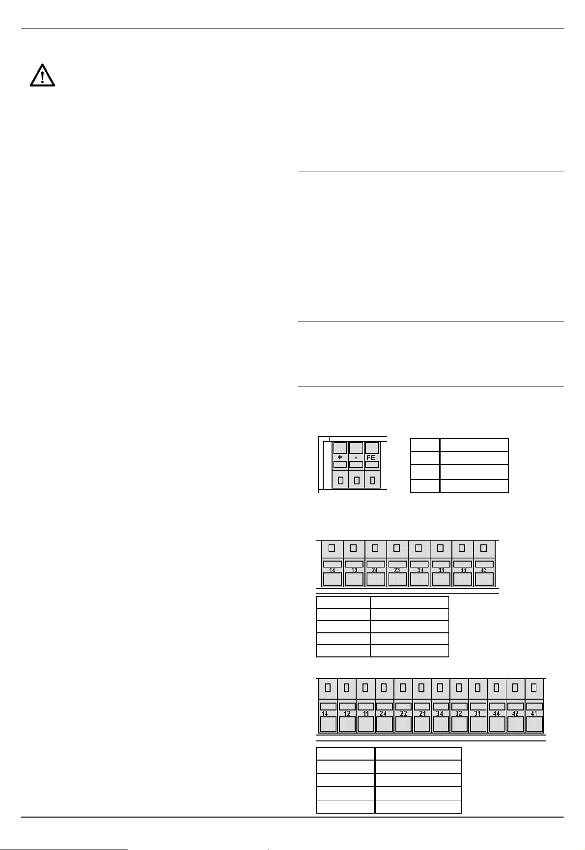
8. Terminal Assignments
8. 1 Input / Voltage-Supply
Pin Determination
Plus (24V)
+
Gnd
-
functional earth
FE
FE should be grounded with wiring as short as possible.
8.2 Output / NO Contacts 789-601
• Leaving via LRN-Button
ð multiple operation of LRN-button
ð Receiver leaves LRN-Mode (after channel 4)
LED „LRN“OFF
Pin no. Determination
13, 14 NO Contact Ch. 1
5.8 Selective Deleting of single Transmitter / LRN Button
Please observe, the transmission range is reduced to appr.
5 mtrs, even if transmitters should be deleted!
1. Switch Receiver into LRN-Mode
ð Press LRN-Button
ð LRN-Mode active - LED „LRN“ON
ð LED of 1. Channel flashes
2. Select channel to be „unlearned“
ð Press LRN-Button again
ð LED of next channel flashes
3. Operate button / switch on transmitter (submit telegramm)
ð LED of sel. Channel is 4s OFF
ð Receiver leaves LRN-Mode
LED „LRN“OFF
23, 24 NO Contact Ch. 2
33, 34 NO Contact Ch. 3
43, 44 NO Contact Ch. 4
8.3 Output / CO Contacts 789-602
Pin no. Determination
11, 12, 14 CO Contacts Ch. 1
21, 22, 24 CO Contacts Ch. 2
31, 32, 34 CO Contacts Ch. 3
41, 42, 44 CO Contacts Ch. 4
WAGO Kontakttechnik GmbH & Co. KG, D-32423 Minden, Hansastraße 27 •www.wago.com 9970-0966/0789-0601/08-07_SW03
Page 3

Mounting - and Installation Instructions 789-601 / 789-602 incl. Versions /xxx- xxx
Current consumtion (internal)
Delay-time (Transmitter /
Output current (per Channel)
Potential bonding
Page 3
9. Technical Data
Designation
Item-no. 789-601 789-602
Supply voltage
No. of channels / outputs
No. Of receive-channels
Max sw itching frequency.
ouput command)
Type of contacts NO contacts CO contacts
Sw itching voltage
Fusing of Loads
max. 16A, AC1 max. 8A, AC1
Type of load
Supply / Atenna
Supply / Contacts
Channel / Channel
Open Contacts
Ambient temperature
Storage temperature
Relative humidity
Degree of pollution
Degree of protection
Mounting position
Terminals
Stripping length
Housing
Mounting
Dimensions (w x h x d)
Approvals
85% w ithout condensation
WAGO CAGE-CLAMP (R) Series 236
Modular Installation Housing
KEMA; acc. EN 60669-2-1:1996
Data
DC24V –15/+20%
Max. 90mA
4
40 / 10 per output
5 Hz
< 100ms
typ. 40...70ms
230V ~
Wire breaker; max. 16A
see table 8.1
-
4 kV eff.
2,2 kV eff.
1 kV eff.
0 ... +55°C
-25 ... + 85°C
2
IP20
optional
5 - 6 mm
DIN Rail acc. EN 50022
appr. 70 x 90 x 55 mm
9.1 Max. permissible Load acc. to EN60669-2-1
Product Type
Type of load 789-601 789-602
halogen lamps 1400W 1400W
incandescent lamps 2200W 1840W
iron-core transformer 120VA 120VA
fluorescent lamps 4AX capazitive loads 60µF motorload 2A 2A
9.2 Max. DC Load Breaking Capacity
9.3 Data Processing of PTM / STM Data
The Radio Receiver is analyzing binary data from different
types of radio transmitters which are based on the EnOcean
Radio Techno-logy. From following type of modules data could
be processed:
Module type EnOcean Application
PTM 100, 200, 230 push-buttons
STM250 window-contacts
STM100 industrial sensors / switches
From the data telegrams the following bits are used:
Des. Org- DataEnOcean Byte Typ Byte Bit
PTM100 5 RPS 3 4...7
PTM200 5 RPS 3 4...7
PTM230 5 RPS 3 4...7
STM100 7 4BS 0 0
STM250 6 1BS 3 0
10. Accessories
Antenna: WAGO 758-910 incl. 2.5 m RG174-cable and SMA-
Connector.
11. General Advices for EnOcean Radio Technology
11.1 Safety Advices conc. R&TTE: Danger
The radio receiver modules must not be used in any
relation with equipment that supports, directly or
indirectly, human health or life or with applications
that can result in danger for people, animals or real
value.
This results from the classification of the radio receiver module
in “Class 2 Equipment”according to ETSI EN 301 489-3 V1.4.1
(2202-08) "Specific conditions for short-range devices (SRD)".
11.2 Details for Transmission Range
The transmission ranges are mainly depending on mounting
and positioning as well as type of material which is used in
buildings. The type of used materials and thickness of walls
have a main influence to the quality and the strength of radio
data.
It is recommended to make tests of data transmission at
desired mounting positions before installation.
DC breaking capacity
of 789-601
DC breaking capacity
of 789-602
11.3 Typical max. Transmission Ranges
1) Visual contacts: typ. 30 m in passages, up to 100 m in halls
2) Rigypsum walls/ wood: typ. 30 m range through max. 5 walls
3) Brick wall /Gas concrete: typ. 20 m range through max. 3
walls
4) reinforcedsconcrete /-ceiling: typ. 10 m range through max. 1
wall
Supply blocks and lift shafts should be seen as a
compartmentalisation.
11.4 Reduction of Transmission Range
Restriction of the transmission range can also be due to:
•Hollow lightweight walls with insulating wool on metal foil
•suspend ceilings with panels made of metal
•carbon fiber, lead glass or glass with metal coating, metal
furniture
•metal wall mounting of the switch.
In addition, the angle with which the signal arrives at the wall is
of great importance. Depending on the angle, the effective wall
strength and thus the damping attenuation of the signal
changes. If possible, the signals should run vertically through
the walling. Walling recesses should be avoided.
For mounting and installation of transmitters please
observe additionally the advices provided by the
manufacturer!
WAGO Kontakttechnik GmbH & Co. KG, D-32423 Minden, Hansastraße 27 •www.wago.com 9970-0966/0789-0601/08-07_SW03
Page 4

Mounting - and Installation Instructions 789-601 / 789-602 incl. Versions /xxx- xxx
12. EC Certificates of Conformity
Page 4
WAGO Kontakttechnik GmbH & Co. KG, D-32423 Minden, Hansastraße 27 •www.wago.com 9970-0966/0789-0601/08-07_SW03
 Loading...