

Page 1
Data sheet | Item number:788-906
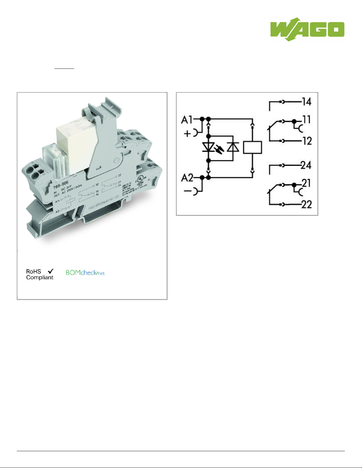
Relay module; Nominal input voltage: 24 VDC; 2 changeover contacts;
Limiting continuous current: 8 A; Green status indicator; Module width: 15
mm
Similiar to picture
788-906
02.05.2019Page /1 11
Page 2
Data sheet | Item number:788-906
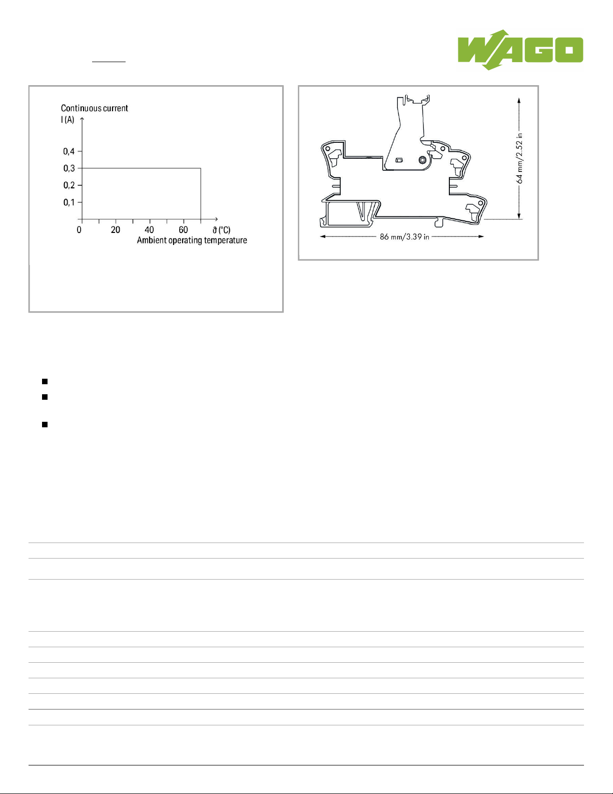
Current-carrying capacity curve
Item description
Note:
Reinforced insulation between coil and contacts
A separator plate (e.g., 209-191) must be used for voltages greater than 250 V between adjacent relay modules and for compliance with the
reinforced insulation requirements.
To protect the relay coils and contacts, inductive loads must be dampened with an effective protection circuit.
Data
Technical Data
Control circuit
Nominal input voltage U
N
DC24V
Input voltage range -15 … +10%
Nominal input current at U
N
30mA
Load circuit:
Number of changeover/switchover contacts 2
Contact material (relay) AgNi + Au
Limiting continuous current 0.3A
Max. switching voltage AC60V
Max. switching power (resistive) AC18VA
Recommended minimum load 0.1V/ 1mA/ 1mW
Min. switching current 0µA
788-906
02.05.2019Page /2 11
Page 3

Data sheet | Item number:788-906
Pull-in time (typ.) 15 ms
Drop-out time (typ.) 12ms
Drop-out time ≤0µs
Electrical life (N.O.; resistive load; 23 °C)
200x 10 switching operations
3
Mechanical life (N.O.; resistive load; 23 °C)
50x 10 switching operations
6
Max. switching load with load/without load
6min / 600min
-1 -1
Signaling
Status indication LED green
Safety and protection:
Rated voltage 250 V
Rated impulse voltage 4 kV
Pollution degree 2
Dielectric strength, control/load circuit (AC, 1 min) 4kVrms
Dielectric strength open contact (AC, 1 min) 1.5kVrms
Dielectric strength, load/load circuit (AC, 1 min) 2.5kVrms
Protection class IP20
Connection data
Connection technology
Push-in CAGE CLAMP
®
Solid conductor 0.34 … 2.5mm²/ 22 … 14AWG
Fine-stranded conductor 0.34 … 2.5mm²/ 22 … 14AWG
Strip length 9 … 10mm/ 0.35 … 0.39inch
Geometrical Data
Width 15mm/ 0.591inch
Height from upper-edge of DIN-35 rail 64mm/ 2.52inch
Depth 86mm/ 3.386inch
Mechanical data
Type of mounting DIN-35 rail
Material Data
Fire load 0 MJ
Weight 50 g
788-906
02.05.2019Page /3 11
Page 4

Data sheet | Item number:788-906
Environmental Requirements
Pollution degree 2
Surrounding air (operating) temperature at U
N
-40 … 70°C
Surrounding air (storage) temperature -40 … 70°C
Processing temperature -25 … +50°C
Surrounding air (operating) temperature for UL -25 … 40 °C
Standards and specifications
Standards/specifications EN 61010-2-201, EN 50205, EN 61810-3; UL 508 (max. 40 °C)
Commercial data
Product Group 6 (Interface Electronics)
Country of origin DE
GTIN 4045454515126
Customs Tariff No. 85364900990
Approvals / Certificates
UL-Approvals
Logo Approval Additional Approval Text
Certificate
name
UL
UL International Netherlands B.V. (ORDINARY
LOCATIONS)
UL 508 E175199
Sec.6
Compatible products
ferrule
Item no.: 216-241
Ferrule; Sleeve for 0.5 mm² / 20 AWG; insulated; electro-tin plated; electrolytic copper; gastight
crimped; acc. to DIN 46228, Part 4/09.90
216-241
Item no.: 216-242
Ferrule; Sleeve for 0.75 mm² / 18 AWG; insulated; electro-tin plated; electrolytic copper; gastight
crimped; acc. to DIN 46228, Part 4/09.90
216-242
Item no.: 216-243
Ferrule; Sleeve for 1 mm² / AWG 18; insulated; electro-tin plated; electrolytic copper; gastight crimped;
acc. to DIN 46228, Part 4/09.90
216-243
Item no.: 216-244
788-906
02.05.2019Page /4 11
Page 5

Data sheet | Item number:788-906
Item no.: 216-244
Ferrule; Sleeve for 1.5 mm² / AWG 16; insulated; electro-tin plated; electrolytic copper; gastight
crimped; acc. to DIN 46228, Part 4/09.90
216-244
Item no.: 216-542
Twin ferrule; Sleeve for 2 x 1 mm² / AWG 2 x 18; red, insulated; 12 mm long
216-542
Jumper
Item no.: 788-113
Comb-style jumper bar; 2-way; insulated
788-113
Item no.: 788-114
Comb-style jumper bar; 3-way; insulated
788-114
Item no.: 788-115
Comb-style jumper bar; 4-way; insulated
788-115
Item no.: 788-116
Comb-style jumper bar; 6-way; insulated
788-116
Item no.: 788-117
Comb-style jumper bar; 8-way; insulated
788-117
Item no.: 788-118
Comb-style jumper bar; 2-way (1-3); insulated
788-118
Item no.: 859-402
Push-in type jumper bar; 2-way; Nominal current 18 A; insulated
859-402
Item no.: 859-402/000-005
Push-in type jumper bar; 2-way; Nominal current 18 A; insulated
859-402
/000-005
Item no.: 859-402/000-006
Push-in type jumper bar; 2-way; Nominal current 18 A; insulated
859-402
/000-006
Item no.: 859-402/000-029
Push-in type jumper bar; 2-way; Nominal current 18 A; insulated
859-402
/000-029
tools
Item no.: 210-720
Operating tool with partially insulated shaft; Type 2, blade (3.5 x 0.5) mm
210-720
General accessories
Item no.: 209-145
Group marker carrier
209-145
Item no.: 209-184
Protection cover
209-184
Item no.: 249-105
Group marker carrier
249-105
Item no.: 788-120
Accessories for relay modules; Operation status indicator: red
788-120
Marking accessories
788-906
02.05.2019Page /5 11
Page 6

Data sheet | Item number:788-906
Item no.: 2009-110
Marking strips; on reel; not stretchable; plain; snap-on type
2009-110
Item no.: 2009-115
WMB-Inline; for Smart Printer; on reel; stretchable 5 - 5.2 mm; plain; snap-on type
2009-115
Item no.: 2009-115/000-002
WMB-Inline; for Smart Printer; on reel; stretchable 5 - 5.2 mm; plain; snap-on type
2009-115
/000-002
Item no.: 2009-115/000-006
WMB-Inline; for smartPRINTER; on reel; stretchable 5 - 5.2 mm; plain; snap-on type
2009-115
/000-006
Item no.: 2009-115/000-007
WMB-Inline; for Smart Printer; on reel; stretchable 5 - 5.2 mm; plain; snap-on type
2009-115
/000-007
Item no.: 2009-115/000-012
WMB-Inline; for smartPRINTER; on reel; stretchable 5 - 5.2 mm; plain; snap-on type
2009-115
/000-012
Item no.: 2009-115/000-017
WMB-Inline; for Smart Printer; on reel; stretchable 5 - 5.2 mm; plain; snap-on type
2009-115
/000-017
Item no.: 2009-115/000-023
WMB-Inline; for Smart Printer; on reel; stretchable 5 - 5.2 mm; plain; snap-on type
2009-115
/000-023
Item no.: 209-128
Adaptor
209-128
Item no.: 209-183
Marker card
209-183
Item no.: 210-110
Fiber-tip pen
210-110
Item no.: 793-501
WMB marking card; as card; not stretchable; plain; snap-on type
793-501
Item no.: 793-501/000-002
WMB marking card; as card; not stretchable; plain; snap-on type
793-501
/000-002
Item no.: 793-501/000-005
WMB marking card; as card; not stretchable; plain; snap-on type
793-501
/000-005
Item no.: 793-501/000-006
WMB marking card; as card; not stretchable; plain; snap-on type
793-501
/000-006
Item no.: 793-501/000-007
WMB marking card; as card; not stretchable; plain; snap-on type
793-501
/000-007
788-906
02.05.2019Page /6 11
Page 7

Data sheet | Item number:788-906
Item no.: 793-501/000-012
WMB marking card; as card; not stretchable; plain; snap-on type
793-501
/000-012
Item no.: 793-501/000-017
WMB marking card; as card; not stretchable; plain; snap-on type
793-501
/000-017
Item no.: 793-501/000-023
WMB marking card; as card; not stretchable; plain; snap-on type
793-501
/000-023
Item no.: 793-501/000-024
WMB marking card; as card; not stretchable; plain; snap-on type
793-501
/000-024
Item no.: 793-502
WMB marking card; as card; MARKED; 1 ... 10 (10x); not stretchable; Horizontal marking; snap-on type
793-502
Item no.: 793-502/000-002
WMB marking card; as card; MARKED; 1 ... 10 (10x); not stretchable; Horizontal marking; snap-on type
793-502
/000-002
Item no.: 793-502/000-005
WMB marking card; as card; MARKED; 1 ... 10 (10x); not stretchable; Horizontal marking; snap-on type
793-502
/000-005
Item no.: 793-502/000-006
WMB marking card; as card; MARKED; 1 ... 10 (10x); not stretchable; Horizontal marking; snap-on type
793-502
/000-006
Item no.: 793-502/000-007
WMB marking card; as card; MARKED; 1 ... 10 (10x); not stretchable; Horizontal marking; snap-on type
793-502
/000-007
Item no.: 793-502/000-012
WMB marking card; as card; MARKED; 1 ... 10 (10x); not stretchable; Horizontal marking; snap-on type
793-502
/000-012
Item no.: 793-502/000-017
WMB marking card; as card; MARKED; 1 ... 10 (10x); not stretchable; Horizontal marking; snap-on type
793-502
/000-017
Item no.: 793-502/000-023
WMB marking card; as card; MARKED; 1 ... 10 (10x); not stretchable; Horizontal marking; snap-on type
793-502
/000-023
Item no.: 793-502/000-024
WMB marking card; as card; MARKED; 1 ... 10 (10x); not stretchable; Horizontal marking; snap-on type
793-502
/000-024
Item no.: 793-503
WMB marking card; as card; MARKED; 11 ... 20 (10x); not stretchable; Horizontal marking; snap-on type
793-503
Item no.: 793-503/000-002
WMB marking card; as card; MARKED; 11 ... 20 (10x); not stretchable; Horizontal marking; snap-on type
793-503
/000-002
788-906
02.05.2019Page /7 11
Page 8

Data sheet | Item number:788-906
Item no.: 793-503/000-005
WMB marking card; as card; MARKED; 11 ... 20 (10x); not stretchable; Horizontal marking; snap-on type
793-503
/000-005
Item no.: 793-503/000-006
WMB marking card; as card; MARKED; 11 ... 20 (10x); not stretchable; Horizontal marking; snap-on type
793-503
/000-006
Item no.: 793-503/000-007
WMB marking card; as card; MARKED; 11 ... 20 (10x); not stretchable; Horizontal marking; snap-on type
793-503
/000-007
Item no.: 793-503/000-012
WMB marking card; as card; MARKED; 11 ... 20 (10x); not stretchable; Horizontal marking; snap-on type
793-503
/000-012
Item no.: 793-503/000-017
WMB marking card; as card; MARKED; 11 ... 20 (10x); not stretchable; Horizontal marking; snap-on type
793-503
/000-017
Item no.: 793-503/000-023
WMB marking card; as card; MARKED; 11 ... 20 (10x); not stretchable; Horizontal marking; snap-on type
793-503
/000-023
Item no.: 793-503/000-024
WMB marking card; as card; MARKED; 11 ... 20 (10x); not stretchable; Horizontal marking; snap-on type
793-503
/000-024
Item no.: 793-504
WMB marking card; as card; MARKED; 21 ... 30 (10x); not stretchable; Horizontal marking; snap-on type
793-504
Item no.: 793-504/000-002
WMB marking card; as card; MARKED; 21 ... 30 (10x); not stretchable; Horizontal marking; snap-on type
793-504
/000-002
Item no.: 793-504/000-005
WMB marking card; as card; MARKED; 21 ... 30 (10x); not stretchable; Horizontal marking; snap-on type
793-504
/000-005
Item no.: 793-504/000-006
WMB marking card; as card; MARKED; 21 ... 30 (10x); not stretchable; Horizontal marking; snap-on type
793-504
/000-006
Item no.: 793-504/000-012
WMB marking card; as card; MARKED; 21 ... 30 (10x); not stretchable; Horizontal marking; snap-on type
793-504
/000-012
Item no.: 793-504/000-017
WMB marking card; as card; MARKED; 21 ... 30 (10x); not stretchable; Horizontal marking; snap-on type
793-504
/000-017
Item no.: 793-504/000-023
WMB marking card; as card; MARKED; 21 ... 30 (10x); not stretchable; Horizontal marking; snap-on type
793-504
/000-023
Item no.: 793-505
WMB marking card; as card; MARKED; 31 ... 40 (10x); not stretchable; Horizontal marking; snap-on type
793-505
788-906
02.05.2019Page /8 11
Page 9

Data sheet | Item number:788-906
Item no.: 793-505/000-005
WMB marking card; as card; MARKED; 31 ... 40 (10x); not stretchable; Horizontal marking; snap-on type
793-505
/000-005
Item no.: 793-505/000-006
WMB marking card; as card; MARKED; 31 ... 40 (10x); not stretchable; Horizontal marking; snap-on type
793-505
/000-006
Item no.: 793-505/000-007
WMB marking card; as card; MARKED; 31 ... 40 (10x); not stretchable; Horizontal marking; snap-on type
793-505
/000-007
Item no.: 793-505/000-012
WMB marking card; as card; MARKED; 31 ... 40 (10x); not stretchable; Horizontal marking; snap-on type
793-505
/000-012
Item no.: 793-506
WMB marking card; as card; MARKED; 41 ... 50 (10x); not stretchable; Horizontal marking; snap-on type
793-506
Item no.: 793-506/000-005
WMB marking card; as card; MARKED; 41 ... 50 (10x); not stretchable; Horizontal marking; snap-on type
793-506
/000-005
Item no.: 793-506/000-006
WMB marking card; as card; MARKED; 41 ... 50 (10x); not stretchable; Horizontal marking; snap-on type
793-506
/000-006
Item no.: 793-506/000-012
WMB marking card; as card; MARKED; 41 ... 50 (10x); not stretchable; Horizontal marking; snap-on type
793-506
/000-012
Item no.: 793-506/000-017
WMB marking card; as card; MARKED; 41 ... 50 (10x); not stretchable; Horizontal marking; snap-on type
793-506
/000-017
Item no.: 793-5501
WMB marking card; as card; for terminal block width 5 - 17.5 mm; stretchable 5 - 5.2 mm; plain; snap-on
type
793-5501
Item no.: 793-5501/000-002
WMB marking card; as card; for terminal block width 5 - 17.5 mm; stretchable 5 - 5.2 mm; plain; snap-on
type
793-5501
/000-002
Item no.: 793-5501/000-005
WMB marking card; as card; stretchable 5 - 5.2 mm; plain; snap-on type
793-5501
/000-005
Item no.: 793-5501/000-006
WMB marking card; as card; stretchable 5 - 5.2 mm; plain; snap-on type
793-5501
/000-006
Item no.: 793-5501/000-007
WMB marking card; as card; stretchable 5 - 5.2 mm; plain; snap-on type
793-5501
/000-007
Item no.: 793-5501/000-012
WMB marking card; as card; stretchable 5 - 5.2 mm; plain; snap-on type
793-5501
/000-012
788-906
02.05.2019Page /9 11
Page 10

Data sheet | Item number:788-906
Item no.: 793-5501/000-014
WMB marking card; as card; stretchable 5 - 5.2 mm; plain; snap-on type
793-5501
/000-014
Item no.: 793-5501/000-017
WMB marking card; as card; stretchable 5 - 5.2 mm; plain; snap-on type
793-5501
/000-017
Item no.: 793-5501/000-023
WMB marking card; as card; stretchable 5 - 5.2 mm; plain; snap-on type
793-5501
/000-023
Item no.: 793-5501/000-024
WMB marking card; as card; stretchable 5 - 5.2 mm; plain; snap-on type
793-5501
/000-024
Item no.: 793-566
WMB marking card; as card; MARKED; 1 ... 50 (2x); not stretchable; Horizontal marking; snap-on type
793-566
Item no.: 793-566/000-002
WMB marking card; as card; MARKED; 1 ... 50 (2x); not stretchable; Horizontal marking; snap-on type
793-566
/000-002
Item no.: 793-566/000-005
WMB marking card; as card; MARKED; 1 ... 50 (2x); not stretchable; Horizontal marking; snap-on type
793-566
/000-005
Item no.: 793-566/000-006
WMB marking card; as card; MARKED; 1 ... 50 (2x); not stretchable; Horizontal marking; snap-on type
793-566
/000-006
Item no.: 793-566/000-007
WMB marking card; as card; MARKED; 1 ... 50 (2x); not stretchable; Horizontal marking; snap-on type
793-566
/000-007
Item no.: 793-566/000-012
WMB marking card; as card; MARKED; 1 ... 50 (2x); not stretchable; Horizontal marking; snap-on type
793-566
/000-012
Item no.: 793-566/000-017
WMB marking card; as card; MARKED; 1 ... 50 (2x); not stretchable; Horizontal marking; snap-on type
793-566
/000-017
Item no.: 793-566/000-023
WMB marking card; as card; MARKED; 1 ... 50 (2x); not stretchable; Horizontal marking; snap-on type
793-566
/000-023
Item no.: 793-566/000-024
WMB marking card; as card; MARKED; 1 ... 50 (2x); not stretchable; Horizontal marking; snap-on type
793-566
/000-024
Downloads
Documentation
Bid Text
788-906
Apr 4, 2012 doc
Download
788-906
02.05.2019Page /10 11
Page 11

Data sheet | Item number:788-906
Relaisbaustein 27.6 kB
Instruction Leaflet
Socket with Relay or SSR pdf
2.1 MB
Download
Additional Information
Disposal; Electrical and electronic equipment, Packaging V 1.0.0 pdf
265.8 kB
Download
CAD/CAE - Smart Data
CAD data
3D Download 788-906 URL Download
788-906
Subject to changes.
02.05.2019Page /11 11
 Loading...