

Page 1

Pos: 2 /Do kume ntati on allg em ein /Ei nba nd/Ei nb and H and buc h - D ec kblatt o hne Var iant en feld ( St an dard) @ 9\ mod_1285229289866_0.doc @ 64941 @ @ 1
Manual
EPSITRON®
Mode Power Supply with Integrated
Switched-
Pos: 3 /Alle Seri en ( Allg em ein e Mod ule) /H inw eise zur Do ku ment ati on/I mpr essu m für St a ndard han dbüc h er - all g. Ang aben, Anschri fte n, Telef onnu mmer n und E-Mail -Adr ess en @ 3\ mod_1219151118203_21.doc @ 21060 @ @ 1
UPS Charger and Controller
787-1675
Version 1.0.0
Page 2

2 EPSITRON®
787-1675 Switched-Mode Power Supply with Integrated UPS Charger and Controller
© 2013 by WAGO Kontakttechnik GmbH & Co. KG
All rights reserved.
WAGO Kontakttechnik GmbH & Co. KG
Hansastraße 27
D-32423 Minden
Phone: +49 (0) 571/8 87 – 0
Fax: +49 (0) 571/8 87 – 1 69
E-Mail: info@wago.com
Web: http://www.wago.com
=== Ende der Li st e für Te xtm arke Ei nba nd_ vorn e ===
Technical Support
Phone: +49 (0) 571/8 87 – 5 55
Fax: +49 (0) 571/8 87 – 85 55
E-Mail: support@wago.com
Every conceivable measure has been taken to ensure the accuracy and
completeness of this documentation. However, as errors can never be fully
excluded, we always appreciate any information or suggestions for improving the
documentation.
E-Mail: documentation@wago.com
We wish to point out that the software and hardware terms as well as the
trademarks of companies used and/or mentioned in the present manual are
generally protected by trademark or patent.
Manual
Version 1.0.0
Page 3

EPSITRON® Table of Contents 3
787-1675 Switched-Mode Power Supply with Integrated UPS Charger and Controller
Pos: 5 /Dok ument ati on allg em ein/ Verz eic hni sse /Inh alts ver zei chni s - Ü ber schr ift oG und Ver zeic hni s @ 3\ mod_1219151230875_21.doc @ 21063 @ @ 1
Table of Contents
1 Notes about this Documentation ................................................................. 5
1.1 Copyright ................................................................................................... 5
1.2 Symbols ..................................................................................................... 6
1.3 Number Notation ....................................................................................... 8
1.4 Font Conventions ...................................................................................... 8
2 Important Notes ........................................................................................... 9
2.1 Legal Bases ............................................................................................... 9
2.1.1 Subject to Changes ............................................................................... 9
2.1.2 Personnel Qualifications ....................................................................... 9
2.1.3 Use of the 787 Series in Compliance with Underlying Provisions ...... 9
2.1.4 Technical Condition of Specified Devices ......................................... 10
2.2 Safety Advice (Precautions) .................................................................... 11
3 Device Description ..................................................................................... 13
3.1 View ........................................................................................................ 14
3.2 Connectors ............................................................................................... 15
3.2.1 Supply ................................................................................................. 15
3.2.2 Load .................................................................................................... 15
3.2.3 Battery, Control and Signaling Contacts ............................................ 16
3.2.4 RS-232 Interface ................................................................................. 16
3.3 Display Elements .................................................................................... 17
3.4 Operating Elements ................................................................................. 18
3.4.1 Rotary Switch for Output Voltage ...................................................... 18
3.4.2 Rotary Switch for Timed Buffer Mode .............................................. 18
3.5 Technical Data ........................................................................................ 19
3.5.1 Device Data ........................................................................................ 19
3.5.2 Technical Data "Input" ....................................................................... 19
3.5.3 Technical Data "Output" .................................................................... 20
3.5.3.1 Technical Data for the Output during Operation with Mains System20
3.5.3.2 Technical Data for the Output during Battery Mode ..................... 20
3.5.4 Technical Data "Signaling" ................................................................ 22
3.5.5 Technical Data "Interface" ................................................................. 22
3.5.6 Technical Data "Ambient Conditions" ............................................... 23
3.5.7 Miscellaneous Data ............................................................................ 23
3.6 Approvals ................................................................................................ 24
3.7 Standards and Guidelines ........................................................................ 25
4 Mounting ..................................................................................................... 26
4.1 Mounting the EPSITRON® Device on the DIN 35 Rail .......................... 26
4.2 Removing the EPSITRON® Device from the DIN 35 Rail ..................... 26
5 Connect Devices ......................................................................................... 27
5.1 Connection Example ............................................................................... 27
6 Function Description ................................................................................. 28
6.1 Tripping of Circuit Breakers ................................................................... 28
6.2 Signaling via LEDs ................................................................................. 29
6.3 Signaling via the Signal Outputs ............................................................. 29
Manual
Version 1.0.0
Page 4

4 Table of Contents EPSITRON®
787-1675 Switched-Mode Power Supply with Integrated UPS Charger and Controller
6.4 Automatic Detection of Battery Modules ............................................... 30
6.4.1 Battery Charging ................................................................................ 30
6.4.1.1 Connecting the 787 Series Battery Modules ................................. 30
6.4.1.2 Connecting a Battery Module from a Third-Party Manufacturer .. 31
6.5 Battery Testing ........................................................................................ 31
6.5.1 Charging ............................................................................................. 31
6.5.2 Presence Test ...................................................................................... 31
6.5.3 Quality Test ........................................................................................ 32
6.5.4 Replacement ....................................................................................... 32
6.6 Battery Mode ........................................................................................... 32
6.6.1 Switch-On Threshold for Battery Mode ............................................. 33
6.6.2 Timed Battery Mode........................................................................... 33
6.6.3 Battery Mode in the IPC Mode ("PC Mode") .................................... 33
6.6.3.1 Delay Time .................................................................................... 34
6.6.3.2 Shut Down PC ............................................................................... 35
6.6.3.3 PC Idle (Off) Time ......................................................................... 35
6.6.4 Deactivating the Battery Mode ........................................................... 36
6.6.5 Deep Discharge Protection during Battery Mode .............................. 36
6.6.6 Recommended Battery Modules ........................................................ 37
=== Ende der Li st e für Te xtm arke Ver zeic hni s_v or ne == =
List of Figures ...................................................................................................... 38
List of Tables ........................................................................................................ 39
Manual
Version 1.0.0
Page 5

EPSITRON® Notes about this Documentation 5
787-1675 Switched-Mode Power Supply with Integrated UPS Charger and Controller
Pos: 7 /Alle Seri en (Allg emei ne Modul e)/Ü bersc hrifte n für all e Seri en/H i nweis zur Do ku ment ati on/H inw eis e z ur D okum enta tio n - Ü ber schr ift 1 @ 4\mod_1237987661750_21.doc @ 29029 @ 1 @ 1
1 Notes about this Documentation
Pos: 8 /Alle S erie n (Al lge mei ne M odul e) /Hin wei se z ur Dok umen tati o n/Hin weis : D oku men tati on aufb ew ahr en @ 4\mod_1237987339812_21.doc @ 29026 @ @ 1
Keep this documentation!
The operating instructions are part of the product and shall be kept for the entire
lifetime of the device. They shall be transferred to each subsequent owner or user
of the device. Care must also be taken to ensure that any supplement to these
instructions are included, if applicable.
Pos: 9 /Seri e 787 ( EP SITR ON) /Hin wei se z ur D oku men tat ion/ Gül tig kei t Do kum ent atio n Unt erbr ec hu ngsfr ei e Str om vers org ung 787- 1675 @ 13\mod_1346059075423_21.doc @ 101963 @ @ 1
This documentation applies to the switched-mode power supply with integrated
ups charger and controller 787-1675.
Pos: 10.1 /Al l e Ser ien ( Al lge mei ne M od ule)/H i nweis e z ur D ok ume ntati on/ Urh eber sc hutz aus führ li ch @ 4\mod_1235565145234_21.doc @ 27691 @ 2 @ 1
1.1 Copyright
This Manual, including all figures and illustrations, is copyright-protected. Any
further use of this Manual by third parties that violate pertinent copyright
provisions is prohibited. Reproduction, translation, electronic and phototechnical
filing/archiving (e.g., photocopying) as well as any amendments require the
written consent of WAGO Kontakttechnik GmbH & Co. KG, Minden, Germany.
Non-observance will involve the right to assert damage claims.
Pos: 10.2 /Dokumentation allgemein/Gliederungselemente/---Seitenwechsel--- @ 3\mod_1221108045078_0.doc @ 21810 @ @ 1
Manual
Version 1.0.0
Page 6
6 Notes about this Documentation EPSITRON®
787-1675 Switched-Mode Power Supply with Integrated UPS Charger and Controller
Pos: 10.3 /Al l e Ser ien ( Al lge mei ne M od ule)/Ü ber sc hrift e n für all e S eri en/Hi nw eis z ur D o kume ntati on/ Sy mbol e - Überschrift 2 @ 13\mod_1351068042408_21.doc @ 105270 @ 2 @ 1
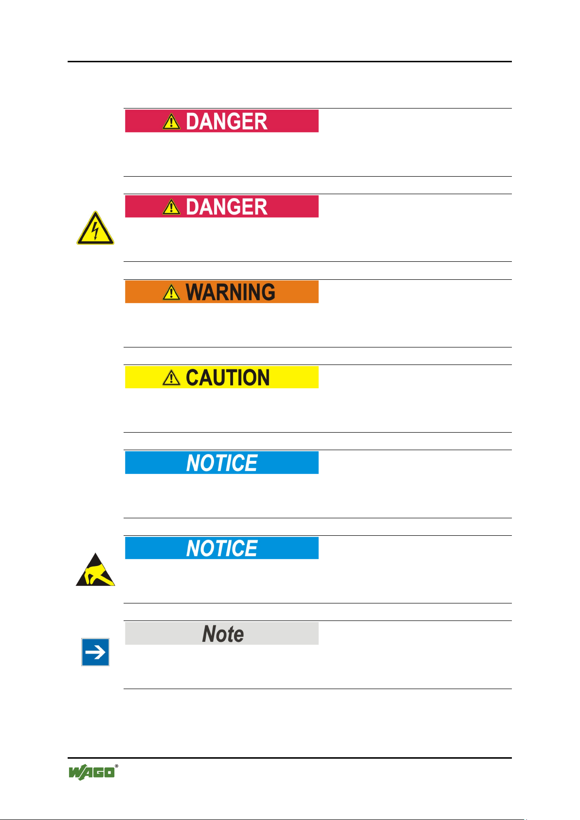
1.2 Symbols
Pos: 10.4.1 /All e Serie n (All gemei ne Mod ule)/ Wichtig e Erlä uteru ngen/ Sich erheits - und sons tig e Hi nw eis e/Gef ahr /G efahr : _War nu ng vor P erso nens ch äde n al lge mei n_ - Erläuterung @ 13\mod_1343309450020_21.doc @ 101029 @ @ 1
Personal Injury!
Indicates a high-risk, imminently hazardous situation which, if not avoided, will
result in death or serious injury.
Pos: 10.4.2 /All e Serie n (All gemei ne Mod ule)/ Wichtig e Erlä uteru ngen/ Sich erheits - und sons tig e Hi nw eis e/Gef ahr /G efahr : _War nu ng vor P erso nens ch äde n dur ch ele ktri sch en S tro m_ - Erläuterung @ 13\mod_1343309694914_21.doc @ 101030 @ @ 1
Personal Injury Caused by Electric Current!
Indicates a high-risk, imminently hazardous situation which, if not avoided, will
result in death or serious injury.
Pos: 10.4.3 /All e Serie n (All gemei ne Mod ule)/ Wichtig e Erlä uteru ngen/ Sich erheits - und sons tig e Hi nw eis e/War n ung/ War nung : _ Warn ung vor Per so nensc hä den allg em ein _ - Erläuterung @ 13\mod_1343309877041_21.doc @ 101035 @ @ 1
Personal Injury!
Indicates a moderate-risk, potentially hazardous situation which, if not avoided,
could result in death or serious injury.
Pos: 10.4.4 /All e Serie n (All gemei ne Mod ule)/ Wichtig e Erlä uteru ngen/ Sich erheits - und sons tig e Hi nw eis e/Vor sic ht/ Vor sicht : _War nung v or P ers onen sch äde n al lge mei n_ - Er läut erung @ 13\mod_1343310028762_21.doc @ 101038 @ @ 1
Personal Injury!
Indicates a low-risk, potentially hazardous situation which, if not avoided, may
result in minor or moderate injury.
Pos: 10.4.5 /All e Serie n (All gemei ne Mod ule)/ Wichtig e Erlä uteru ngen/ Sich erheits - und sonstige Hinweise/Achtung/Achtung: _Warnung vor Sachschäden allgemein_ - Erläuterung @ 13\mod_1343310134623_21.doc @ 101041 @ @ 1
Damage to Property!
Indicates a potentially hazardous situation which, if not avoided, may result in
damage to property.
Pos: 10.4.6 /All e Serie n (All gemei ne Mod ule)/ Wichtig e Erlä uteru ngen/ Sich erheits - und sons tig e Hi nw eis e/Ach tu ng/A cht ung : _ War nung vor Sac hsc häd en d urc h el ektr ost atis ch e Aufl ad ung _ - Erläuterung @ 13\mod_1343310227702_21.doc @ 101044 @ @ 1
Damage to Property Caused by Electrostatic Discharge (ESD)!
Indicates a potentially hazardous situation which, if not avoided, may result in
damage to property.
Pos: 10.4.7 /All e Serie n (All gemei ne Mod ule)/ Wichtig e Erlä uteru ngen/ Sich erheits - und sonstige Hinweise/Hinweis/Hinweis: _Wichtiger Hinweis allgemein_ - Eräuterung @ 13\mod_1343310326906_21.doc @ 101047 @ @ 1
Important Note!
Indicates a potential malfunction which, if not avoided, however, will not result in
damage to property.
Pos: 10.4.8 /All e Serie n (All gemei ne Mod ule)/ Wichtig e Erlä uteru ngen/ Sich erheits - und sons tig e Hi nw eis e/Inf or mati on/I nf orma tio n: _ Wei ter e Inf or mati on allg emei n_ - Erläuterung @ 13\mod_1343310439814_21.doc @ 101051 @ @ 1
Manual
Version 1.0.0
Page 7

EPSITRON® Notes about this Documentation 7
787-1675 Switched-Mode Power Supply with Integrated UPS Charger and Controller
Additional Information:
Refers to additional information which is not an integral part of this
documentation (e.g., the Internet).
Pos: 10.5 /Dokumentation allgemein/Gliederungselemente/---Seitenwechsel--- @ 3\mod_1221108045078_0.doc @ 21810 @ @ 1
Manual
Version 1.0.0
Page 8

8 Notes about this Documentation EPSITRON®
Table 1: Number notation
Number code
Example
Note
Decimal
100
Normal notation
Hexadecimal
0x64
C notation
Binary
'100'
'0110.0100'
In quotation marks, nibble separated with
dots (.)
Table 2: Font conventions
Font type
Indicates
italic
Names of paths and data files are marked in italic-type.
e.g.: C:\Programme\WAGO-I/O-CHECK
Menu
Menu items are marked in bold letters.
e.g.: Save
>
A greater-than sign between two names means the selection of a
e.g.: File > New
Input
Designation of input or optional fields are marked in bold letters,
e.g.: Start of measurement range
“Value”
Input or selective values are marked in inverted commas.
e.g.: Enter the value “4 mA” under Start of measurement range.
[Button]
Pushbuttons in dialog boxes are marked with bold letters in square
e.g.: [Input]
[Key]
Keys are marked with bold letters in square brackets.
e.g.: [F5]
787-1675 Switched-Mode Power Supply with Integrated UPS Charger and Controller
Pos: 10.6 /Al l e Ser ien ( Al lge mei ne M od ule)/H i nweis e z ur D ok ume ntati on/ Za hlens ys tem e @ 3\mod_1221059454015_21.doc @ 21711 @ 2 @ 1
1.3 Number Notation
Pos: 10.7 /Al l e Ser ien ( Al lge mei ne M od ule)/H i nweis e z ur D ok ume ntati on/ Sc hrift ko nvent ion en @ 3 \mod_1221059521437_21.doc @ 21714 @ 2 @ 1
1.4 Font Conventions
Pos: 11 /Dokum entati on allg emei n/Gli ederung sele mente /---Seit enwec hs el--- @ 3\mod_1221108045078_0.doc @ 21810 @ @ 1
menu item from a menu.
brackets.
Manual
Version 1.0.0
Page 9

EPSITRON® Important Notes 9
787-1675 Switched-Mode Power Supply with Integrated UPS Charger and Controller
Pos: 12 /All e S eri en ( Allg emei ne Mod ule) /Ü bers chri fte n f ür al le Seri en/Wi chtig e Erläu terung en/ Wichti ge Erläu terung en - Üb ersc hrift 1 @ 4\ mod_1241428899156_21.doc @ 32170 @ 1 @ 1
2 Important Notes
Pos: 13.1 /Al l e Ser ien ( Al lge mei ne M od ule)/ Wic htig e Er lä uter ung en/ Einl eitu ng Wich tig e Er lä uter ung en @ 3\ mod_1221059818031_21.doc @ 21717 @ @ 1
This section includes an overall summary of the most important safety
requirements and notes that are mentioned in each individual section. To protect
your health and prevent damage to devices as well, it is imperative to read and
carefully follow the safety guidelines.
Pos: 13.2 /Al l e Ser ien ( Al lge mei ne M od ule)/Ü ber sc hrift e n für all e S eri en/ Wich tig e Er läuter ung en /Rec htli c he Gr un dlag en - Über schri ft 2 @ 3\mod_1221060626343_21.doc @ 21726 @ 2 @ 1
2.1 Legal Bases
Pos: 13.3 /Al l e Ser ien ( Al lge mei ne M od ule)/ Wic htig e Er lä uter ung en/ Änd eru ngs vor behal t - Ü bers chr ift 3 u nd I nhal t @ 3\mod_1221060036484_21.doc @ 21720 @ 3 @ 1
2.1.1 Subject to Changes
WAGO Kontakttechnik GmbH & Co. KG reserves the right to provide for any
alterations or modifications that serve to increase the efficiency of technical
progress. WAGO Kontakttechnik GmbH & Co. KG owns all rights arising from
the granting of patents or from the legal protection of utility patents. Third-party
products are always mentioned without any reference to patent rights. Thus, the
existence of such rights cannot be excluded.
Pos: 13.4 /S eri e 7 87 ( EPS ITRO N)/ Wic htig e Er lä uter ung en/ Pers onal qu alif ik atio n 7 87-xxxx @ 11\mod_1317113061338_21.doc @ 79692 @ 3 @ 1
2.1.2 Personnel Qualifications
All sequences implemented on 787 Series devices may only be carried out by
electrical specialists with sufficient knowledge in automation. The specialists
must be familiar with the current norms and guidelines for the devices and
automated environments.
Pos: 13.5 /Serie 787 (EPSITRON)/Wichtige Erläuterungen/Bestimmungsgemäße Verwendung 787-xxxx @ 11\mod_1317113060572_21.doc @ 79688 @ 3 @ 1
2.1.3 Use of the 787 Series in Compliance with Underlying Provisions
The EPSITRON® 787 Series power supply system provides direct current to
electric or electronic devices, such as industrial control systems or display,
communication and measuring devices.
The devices have been developed for use in an environment that meets the IP20
protection class criteria. Protection against finger injury and solid impurities up to
12.5 mm diameter is assured; protection against water damage is not ensured.
Unless otherwise specified, operation of the components in wet and dusty
environments is prohibited.
The devices are designed for installation in an enclosure. Under no circumstances
may they be used in control systems for planes or nuclear facilities, as any
malfunction in these applications could result in severe injuries or risk of death.
Pos: 13.6 /Dokumentation allgemein/Gliederungselemente/---Seitenwechsel--- @ 3\mod_1221108045078_0.doc @ 21810 @ @ 1
Manual
Version 1.0.0
Page 10

10 Important Notes EPSITRON®
787-1675 Switched-Mode Power Supply with Integrated UPS Charger and Controller
Pos: 13.7 /Al l e Ser ien ( Al lge mei ne M od ule)/ Wic htig e Er lä uter ung en/T ec hnisc h er Zu st and der G erät e - Ü bers chrif t 3 und I nhal t @ 3\ mod_1221060446109_21.doc @ 21723 @ 3 @ 1
2.1.4 Technical Condition of Specified Devices
The components to be supplied Ex Works, are equipped with hardware and
software configurations, which meet the individual application requirements.
WAGO Kontakttechnik GmbH & Co. KG will be exempted from any liability in
case of changes in hardware or software as well as to non-compliant usage of
components.
Please send your request for modified and new hardware or software
configurations directly to WAGO Kontakttechnik GmbH & Co. KG.
Pos: 13.8 /Dokumentation allgemein/Gl ieder ung sele men te/---Sei te nwec hsel --- @ 3\mod_1221108045078_0.doc @ 21810 @ @ 1
Manual
Version 1.0.0
Page 11
EPSITRON® Important Notes 11
787-1675 Switched-Mode Power Supply with Integrated UPS Charger and Controller
Pos: 13.9 /All e Serien ( Allge meine Module) /Über schri fte n für alle S erien /Wich tige Er läuter ungen /Sic herhei tshi nweise - Übersc hrift 2 @ 6\mod_1260180299987_21.doc @ 46724 @ 2 @ 1
2.2 Safety Advice (Precautions)
Pos: 13.10 / All e S erie n (Al lge mei ne M o dule) /Wi cht ige Erl äuter ung en /Sic her hei ts- und s onsti ge Hin wei se/E inl eit ung Sic her hei tshi nw eise Har dwar e @ 6\ mod_1260180170493_21.doc @ 46720 @ @ 1
For installing and operating purposes of the relevant device to your system the
following safety precautions shall be observed:
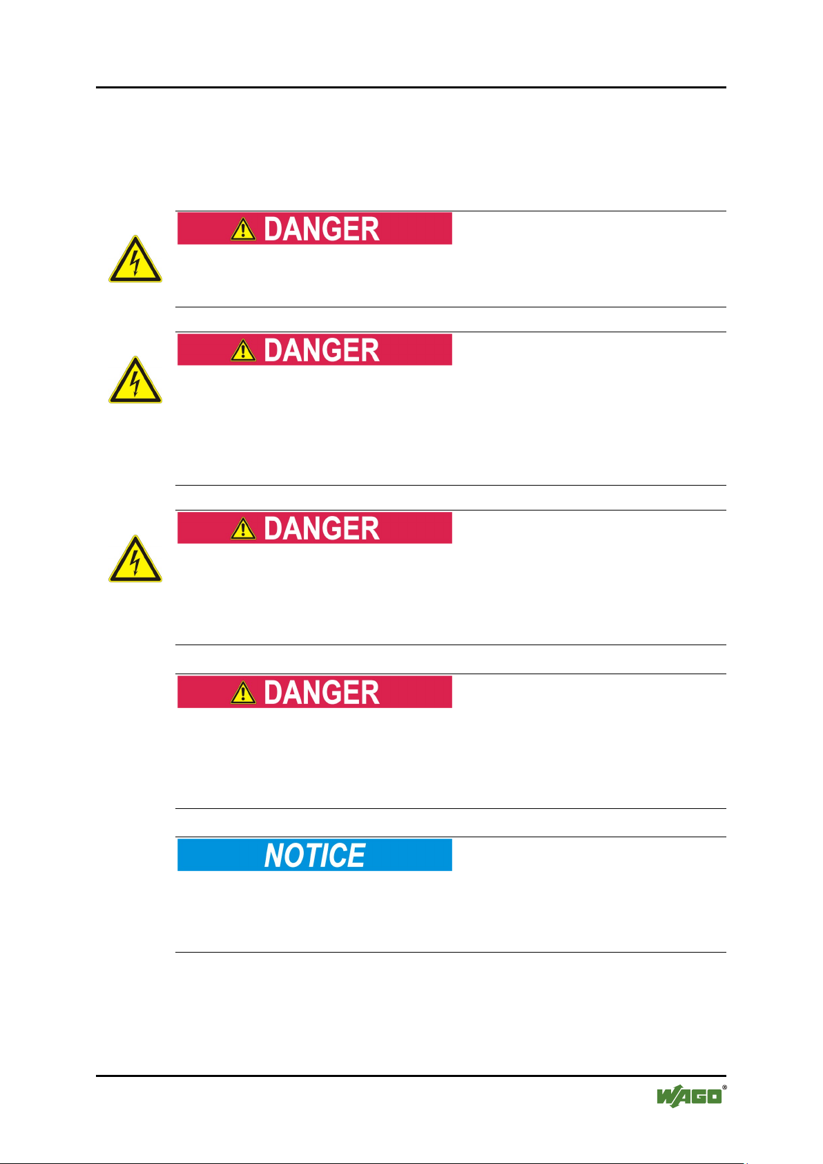
Pos: 13.11 / All e S erie n (Al lge mei ne M o dule) /Wi cht ige Erl äuter ung en /Sic her hei ts- und s onsti ge Hin wei se/G ef ahr/ Gef ahr: Ni cht a n G erät e n unt er Spa nnu ng ar beit en! @ 6\mod_1260180365327_21.doc @ 46727 @ @ 1
Do not work on components while energized!
All power sources to the device shall be switched off prior to performing any
installation, repair or maintenance work.
Pos: 13.12 /Ser ie 787 ( EPSITR ON)/ Wichti ge Erl äuter ungen /Sich erhei ts- und s o nstig e H in weise /G efahr /G efahr : E inb au 787- xxx x nur in Geh äus en, Schr än ken oder el ektr isc hen Betr ie bsr äum en! @ 11 \mod_1317113246230_21.doc @ 79696 @ @ 1
Installation only in appropriate housings, cabinets or in electrical operation
rooms!
Always install devices of the 787 Series in enclosures, cabinets or electrical
equipment rooms which can be closed and locked. Ensure that access to this
equipment/these rooms is possible only by authorized specialists with the
appropriate key or tools.
Pos: 13.13 /Ser ie 787 ( EPSITR ON)/ Wichti ge Erl äuter ungen /Sich erhei ts- und s o nstig e H in weise /G efahr /G efahr : S p annu ng an d en A usgä nge n a uch bei Aus fall der Ne tzs pan nung ! @ 14\mod_1363599131481_21.doc @ 114650 @ @ 1
Voltage present at the load terminals, even on loss of power supply!
Voltage continues to be present at the load terminals even when there is a loss of
power supply and the device switches to the buffer mode! Therefore, never touch
the load terminals! In this case, always remove the jumper between R0 and R1 to
de-energize the load terminals!
Pos: 13.14 / All e S erie n (Al lge mei ne M o dule) /Wi cht ige Erl äuter ung en /Sic her hei ts- und s onsti ge Hin wei se/G ef ahr/ Gef ahr: Un fall ver hüt ungs vor sc hrift en bea chte n! @ 6\ mod_1260180657000_21.doc @ 46735 @ @ 1
Pos: 13.15 /Ser ie 787 ( EPSITR ON)/ Wichti ge Erl äuter ungen /Sich erhei ts- und s o nstig e H in weise /G efahr /G efahr : G erä te nic ht i n St euer ungsa nlag en verw ende n! @ 13\mod_1346400862576_21.doc @ 102180 @ @ 1
Do not use these devices in control systems for planes, trains or nuclear
facilities!
Never use these devices in control systems for planes, trains or nuclear facilities,
as any malfunction in these applications can result in severe injuries or risk of
death!
Pos: 13.16 / All e S erie n (Al lge mei ne M o dule) /Wi cht ige Erl äuter ung en /Sic her hei ts- und so nsti ge Hin weis e/G efahr /G ef ahr: Auf nor mg erec hten Ans chl uss ach te n! @ 6\mod_1260180753479_21.doc @ 46739 @ @ 1
Pos: 13.17 /Ser ie 787 ( EPSITR ON)/ Wichti ge Erl äuter ungen /Sic her hei ts- un d sonsti ge Hin weise /Acht ung/A chtu ng: Vers org ungssp annung bei def ekte m Gerät ab schal ten! @ 13\ mod_1346401405605_21.doc @ 102187 @ @ 1
Switch off power supply to defective device!
Switch off power supply to the device immediately if the device malfunctions or
is damaged! Control systems connected to the device may also be damaged!
Return the defective device directly to WAGO.
Pos: 13.18 / All e S erie n (Al lge mei ne M o dule) /Wi cht ige Erl äuter ungen /Sich erhei ts- un d so nstig e H in weise /Ac htu ng/ Acht ung: G erä te vor kri ec he nde n un d is olier en den Stof fe n sch ütz en! @ 6\mod_1260181036216_21.doc @ 46747 @ @ 1
Manual
Version 1.0.0
Page 12
12 Important Notes EPSITRON®
787-1675 Switched-Mode Power Supply with Integrated UPS Charger and Controller
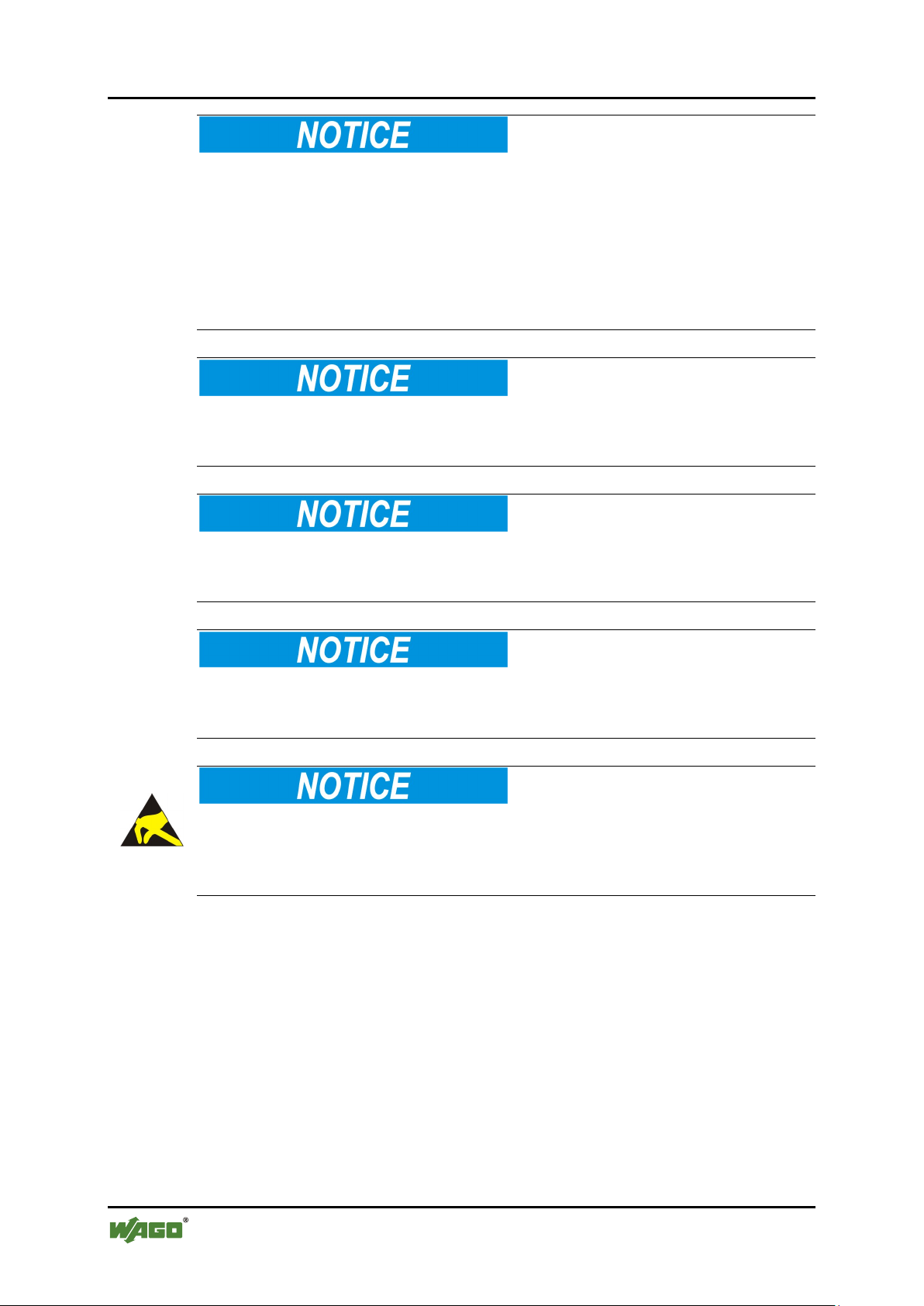
Protect the components against materials having seeping and insulating
properties!
The components are not resistant to materials having seeping and insulating
properties such as: aerosols, silicones and triglycerides (found in some hand
creams). If you cannot exclude that such materials will appear in the component
environment, then install the components in an enclosure being resistant to the
above-mentioned materials. Clean tools and materials are imperative for handling
devices/modules.
Pos: 13.19 / All e S erie n (Al lge mei ne M o dule) /Wi cht ige Erl äuter ung en /Sic her hei ts- und s onsti ge Hin wei se/A cht ung /Ac htung : R ei nig ung nur mit zul ässi ge n Mat eri alie n! @ 6\ mod_1260181203293_21.doc @ 46751 @ @ 1
Cleaning only with permitted materials!
Clean soiled contacts using oil-free compressed air or with ethyl alcohol and
leather cloths.
Pos: 13.20 / Alle Ser ie n (All ge mein e M odul e) /Wic hti ge Erläu ter ung en/ Sic her heit s- un d s onsti ge Hin wei se/Ac ht ung /Ac htung : K ein Ko nta kts pray ver we nden! @ 6 \mod_1260181290808_21.doc @ 46755 @ @ 1
Do not use any contact spray!
Do not use any contact spray. The spray may impair contact area functionality in
connection with contamination.
Pos: 13.21 / Alle S erie n (Al lge mei ne M odul e) /Wi chti ge Erl äuter ung en /Sic her hei ts- un d s onsti ge Hin wei se/A cht ung /Ac htung : V erp olu ng ver mei den! @ 6\ mod_1260184045744_21.doc @ 46767 @ @ 1
Do not reverse the polarity of connection lines!
Avoid reverse polarity of data and power supply lines, as this may damage the
devices involved.
Pos: 13.22 / All e S erie n (Al lge mei ne M o dule) /Wi cht ige Erl äuter ung en /Sic her hei ts- und s onsti ge Hin wei se/A cht ung /Ac htung : E le ktr ostat isc he E ntl adu ng verm eid en! @ 6\ mod_1260181364729_21.doc @ 46759 @ @ 1
Avoid electrostatic discharge!
The devices are equipped with electronic components that you may destroy by
electrostatic discharge when you touch. Pay attention while handling the devices
to good grounding of the environment (persons, job and packing).
Pos: 14 /Dokum entati on allg emei n/Gli ederung sele mente /---Seit enwec hs el--- @ 3\mod_1221108045078_0.doc @ 21810 @ @ 1
Manual
Version 1.0.0
Page 13

EPSITRON® Device Description 13
787-1675 Switched-Mode Power Supply with Integrated UPS Charger and Controller
Pos: 15 /All e S eri en ( Allg emei ne Mod ule) /Ü bers chri fte n f ür al le Ser ien/ Ger äte besc hrei bu ng/G erät e beschr ei bung - Üb erschr if t 1 @ 3 \mod_1233756084656_21.doc @ 27096 @ 1 @ 1
3 Device Description
Pos: 16.1 /S eri e 7 87 ( EPS ITRO N)/ Ger äteb esc hrei bu ng/ Bes chr eibung / An wend ung /An wen dung 78 7-1675 @ 13\mod_1342439897257_21.doc @ 100336 @ @ 1
The switched-mode power supply with integrated ups charger and controller 7871675, in the following named as uninterruptible power supply system (UPS),
ensures that power is always supplied. If the mains power is lost, all of the
electrical loads connected to the system will continue to operate reliably.
Pos: 16.2 /S eri e 7 87 ( EPS ITRO N)/ Ger äteb esc hrei bu ng/ Bes chr eibung /F un kti on/Fu nkti o n 78 7-1675: Funktionseinheiten @ 13\mod_1342599274535_21.doc @ 100540 @ @ 1
The system consists of two function units:
• an AC/DC power supply unit with an integrated charger and controller and
• a 24V DC battery module for buffering (not included in the scope of
supply).
Pos: 16.3 /S eri e 7 87 ( EPS ITRO N)/ Ger äteb esc hrei bu ng/ Bes chr eibung /F un kti on/Fu nkti o n 78 7-167 5: Wir kungs weise der Komponenten @ 13\mod_1342600188912_21.doc @ 100544 @ @ 1
All of the components that can be used to set up an uninterruptible power supply
system are optimally matched to and compatible with one another. These
components can be quickly installed and are immediately ready for operation.
Any 787-87x Series battery modules that are connected to the system are detected
automatically by the UPS.
Pos: 17 /Dokum entati on allg emei n/Gli ederung sele mente /---Seit enwec hs el--- @ 3\mod_1221108045078_0.doc @ 21810 @ @ 1
Battery module not included in the scope of supply!
The scope of supply for this device does not include the battery module. The
device will only continue to operate properly when at least one battery module is
connected. The WAGO range of products includes compatible EPSITRON® 78787x Series battery modules.
The system can also be integrated into an existing topology via several signaling
contacts and a serial interface.
Critical operating states are signaled at an early stage, before the 24 V system
power collapses and the device shuts down.
Manual
Version 1.0.0
Page 14

14 Device Description EPSITRON®
Table 3: Legend for "View" figure
No.
Designation
Reference
1
CAGE CLAMP® connections
for 24 VDC output voltage
"Device description" >
"Connections" > "Load"
2
Rotary switch for setting the output
"Device Description" > "Operating
Output Voltage"
3
CAGE CLAMP® connections
for 100 … 240 VAC input voltage
"Device Description" >
"Connections" > "Power Supply"
4
RS-232 serial interface
"Device Description" >
Interface"
5
LEDs
"Device Description" > "Display
Elements"
6
Rotary switch for setting the timed
"Device Description" > "Operating
Timed Buffer Mode"
7
CAGE CLAMP® connections for
"Device Description" > "Operating
Signaling Contacts"
787-1675 Switched-Mode Power Supply with Integrated UPS Charger and Controller
Pos: 18 /All e S eri en ( Allg emei ne Mod ule) /Ü bers chri fte n f ür al le Ser ien/ Ger äte besc hrei bu ng/A nsi cht - Üb erschr if t 2 @ 4 \mod_1240984217343_21.doc @ 31958 @ 2 @ 1
3.1 View
Pos: 19 /Ser ie 78 7 (EP SITR ON) /Ger ät ebes chr ei bung /Ansi cht/A nsic ht 787-1675 @ 13\mod_1345791639239_21.doc @ 101944 @ @ 1
Figure 1: View of device
voltage
buffer mode
Elements" > "Rotary Switch for
"Connections" > "RS-232
Elements" > "Rotary Switch for
battery, control and signaling contacts
Pos: 20 /Dokum entati on allg emei n/Gli ederung sele mente /---Seit enwec hs el--- @ 3\mod_1221108045078_0.doc @ 21810 @ @ 1
Manual
Version 1.0.0
Elements" > "Battery, Control and
Page 15

EPSITRON® Device Description 15
Table 4: Power supply connections
No.
Designatio
n
Function
1 L Input voltage: 100 … 240 VAC
2 N N-conductor
3
PE
Ground conductor
Table 5: Terminals – Load
No.
Designatio
n
Function
1 + Output voltage: 24 VDC
2 + Output voltage: 24 VDC
3 - Reference potential 0 V
4 - Reference potential 0 V
787-1675 Switched-Mode Power Supply with Integrated UPS Charger and Controller
Pos: 21 /All e S eri en ( Allg emei ne Mod ule) /Ü bers chri fte n f ür al le Ser ien/ Ger äte besc hrei bu ng/A nsc hlüs se - Über schr ift 2 @ 4\mod_1240984262656_21.doc @ 31961 @ 2 @ 1
3.2 Connectors
Pos: 22.1 /S eri e 7 87 ( EPS ITRO N)/ Ger äteb esc hrei bu ng/ Ans chl üss e/Ans chl üss e 78 7-1 675 - Versorgung @ 13\mod_1347952219203_21.doc @ 102916 @ 3 @ 1
3.2.1 Supply
Figure 2: Supply connection
Pos: 22.2 /S eri e 7 87 ( EPS ITRO N)/ Ger äteb esc hrei bu ng/ Ans chl üss e/Ans chl üss e 78 7-1 675 - Last @ 13\mod_1347884939616_21.doc @ 102884 @ 3 @ 1
3.2.2 Load
Figure 3: Load terminals
Pos: 22.3 /S eri e 7 87 ( EPS ITRO N)/ Ger äteb esc hrei bu ng/ Ans chl üss e/Ans chl üss e 78 7-1 675 - Batt erie-, Ste uer- und Signalkontakte @ 13\mod_1347958740665_21.doc @ 102950 @ 3 @ 1
Manual
Version 1.0.0
Page 16

16 Device Description EPSITRON®
Table 6: Connections – Battery, control and signaling contacts
No.
Designatio
n
Function
1
B)
Battery connection 0 V
2
B)
Battery connection 24 V
3
°C
Signal line for "Bat. Control"
4
°C
Signal line for "Bat. Control"
5
R0
Remote shutdown in Buffer mode
6
R1
Remote shutdown in Buffer mode
7
34
Signal output "Bat.Charge"
8
24
Signal output "Bat.Mode"
9
14
Signal output "Alarm"
10
13
External supply voltage 24 VDC
Table 7: Connections – RS-232 interface
No.
Designation
Function
1 1 Transmitter (Tx)
2 2 Receiver (Rx)
3 3 Reference potential 0V
4 4 Output voltage: 24 VDC
787-1675 Switched-Mode Power Supply with Integrated UPS Charger and Controller
3.2.3 Battery, Control and Signaling Contacts
Figure 4: Battery, control and
signaling contacts
Pos: 22.4 /Ser ie 787 (EP SITR ON) /Ger ät ebes chr ei bung /Ans chl üss e/ Ansc hlüs se 787- 1675 - RS-23 2-Sch nittstell e @ 13\mod_1347962772871_21.doc @ 102970 @ 3 @ 1
3.2.4 RS-232 Interface
Figure 5: RS-232 interface
Pos: 23 /All e S eri en ( Allg emei ne Mod ule) /Ü bers chri fte n f ür al le Ser ien/ Ger äte besc hrei bu ng/A nz eig eele ment e - Ü ber schr ift 2 @ 4\ mod_1240984390875_21.doc @ 31964 @ 2 @ 1
for signal outputs 7, 8 and 9.
Manual
Version 1.0.0
Page 17

EPSITRON® Device Description 17
Table 8: Legend for "Indicators" figure
No.
LED
Designation
Explanation:
1
red
Alarm
The unit is faulted, or the Battery mode is
being terminated.
2
yellow
Charge/
Bat. Mode
The unit is charging the batteries, or is
operating in the Battery mode.
3
green
DC OK
The unit is ready for use.
787-1675 Switched-Mode Power Supply with Integrated UPS Charger and Controller
3.3 Display Elements
Pos: 24 /Ser ie 78 7 (EP SITR ON) /Ger ät ebes chr ei bung /Anz eig eel eme nt e/Anz eig eel em ente 787- 1675 @ 13\mod_1346060933352_21.doc @ 101967 @ @ 1
The unit is equipped with three LEDs, which indicate the following statuses:
Figure 6: Display elements
Pos: 25 /Dokumentation allgemein/Gliederung sele men te/---Sei te nwec hsel --- @ 3\mod_1221108045078_0.doc @ 21810 @ @ 1
Further signaling possible!
Other statuses can also be indicated if an error occurs. For information about this,
refer to the "Operating Statuses" table given in this manual.
Manual
Version 1.0.0
Page 18

18 Device Description EPSITRON®
787-1675 Switched-Mode Power Supply with Integrated UPS Charger and Controller
Pos: 26 /All e S eri en ( Allg emei ne Mod ule) /Ü bers chri fte n f ür al le Ser ien/ Ger äte besc hrei bu ng/B edi enel e ment e - Ü bers chri ft 2 @ 4\mod_1239191655456_21.doc @ 30439 @ 2 @ 1
3.4 Operating Elements
Pos: 27 /Ser ie 78 7 (EP SITR ON) /Ger ät ebes chr ei bung /Be die nele men te/B edi enel e ment e 78 7-1675 @ 13\mod_1346060971825_21.doc @ 101981 @ 33 @ 1
3.4.1 Rotary Switch for Output Voltage
The unit is set at the factory for an output voltage of 24 VDC. You can change
this value using the rotary switch. The output voltage can be set to any value
between 23 … 28.5 VDC.
Figure 7: Rotary switch for output voltage
3.4.2 Rotary Switch for Timed Buffer Mode
The unit is set at the factory for battery operation for an indefinite period of time.
You can change this value using the rotary switch. Besides set time periods from
1 ... 20 minutes, the following settings can also be made:
• PC Mode: The unit operates based on a time sequence, which shuts down
an IPC, a control system or display and operator panel in a controlled
manner when battery operation is ended. All default values can be set
individually using the "759-870 V2" configuration software (starting from
Version 2.5).
• Indefinite mode ("∞"): Power supply is maintained until the deep
discharge threshold is reached.
• Custom mode: The timed Battery mode can be set individually using the
"759-870 V2" configuration software (starting from Version 2.5).
Figure 8: Rotary switch for battery operation
Pos: 28 /Dokumentation allgemein/ Gli eder ungs ele ment e/---Seit en wechs el--- @ 3\mod_1221108045078_0.doc @ 21810 @ @ 1
Manual
Version 1.0.0
Page 19

EPSITRON® Device Description 19
Table 9: Device data
Width
60 mm/2.36 in.
Height
127 mm
Height from upper-edge of DIN 35 rail
135.5 mm
Weight
800 g
Table 10: Technical data - "Input"
Nominal input voltage
100 ... 240 VAC
Input voltage range AC
85 ... 264 VAC
Input voltage derating AC
-1.5 %/VAC < 110 VAC
Input voltage range DC
120 ... 372 VDC
Input voltage derating DC
-1 %/VDC < 150 VDC
Frequency range
47 … 63 Hz/
0 Hz
Input current Ie
1.1 A for 230 VAC;
2.2 A for 100 VAC
Inrush current
less than 30 A
Turn-on time
less than 100 ms
Transient overvoltage protection:
Varistor
Discharge current to PE
1 mA
Input fuse (internal)
4 A, slow
Recommended backup fusing:
6 A, 10 A or 16 A
(Characteristic B or C)
Input modules
CAGE CLAMP®, 721 Series;
0.08 mm2 … 2.5 mm2; AWG 28 … 12
787-1675 Switched-Mode Power Supply with Integrated UPS Charger and Controller
Pos: 29 /Alle Seri en (Al lgemei ne Mod ule)/Ü bers chrift en für al le Ser ien/G eräte beschr eibu ng/Tec hnisc he Dat en - Übers chr ift 2 @ 3\mod_1232967587687_21.doc @ 26924 @ 2 @ 1
3.5 Technical Data
Pos: 30 /Ser ie 78 7 (EP SITR ON) /Ger ät ebes chr ei bung /Tec hnis ch e D aten /Tec h nisc he D ate n 78 7-1675 @ 13\mod_1342438358691_21.doc @ 100320 @ 333443333 @ 1
3.5.1 Device Data
3.5.2 Technical Data "Input"
Manual
Version 1.0.0
Page 20

20 Device Description EPSITRON®
Table 11: Technical data - "Output"
Recovery stability
maximum 35 VDC
Overvoltage Protection
38 VDC
Parallel connection of several modules
yes, with a maximum of two modules
decoupled from one another
Series connection of several modules
yes, without any restrictions
Output nominal current
5 A
Tripping of fuses
Maximum B4 power circuit breakers
Output terminals
CAGE CLAMP®, 721 Series;
0.08 mm2 … 2.5 mm2; AWG 28 … 12
Line length
≤ 3 m
Table 12: Technical data for the output during operation with the mains system
Nominal output voltage
24 VDC, SELV
Output voltage range
23 ... 28.5 VDC
Output current limit
starting at approx. 1.1 x nominal
current, constant current
Adjustment accuracy
less than 1 %
Static load change 10 … 90 %
Maximum power loss at nominal load, -
charged battery
22 W
Maximum power loss at nominal load, -
charged battery
17 W
Maximum power loss at nominal load, -
charged
30 W
Efficiency
typically 88 %
Residual ripple
typically 50 mVSS
Table 13: Technical data for the output during Battery mode
Output voltage
24 VDC, SELV
Output voltage range
U
BAT
-0.5 V (27.5 … 19 VDC)
Output current limit
starting at approx. 1.1 x nominal current
Maximum power loss at nominal load
5.2 W
Maximum power loss during opencircuit operation
3.2 W
Remote shutdown
yes
787-1675 Switched-Mode Power Supply with Integrated UPS Charger and Controller
3.5.3 Technical Data "Output"
3.5.3.1 Technical Data for the Output during Operation with Mains System
100VAC input voltage and fully
230VAC input voltage and fully
90VAC input voltage, battery being
3.5.3.2 Technical Data for the Output during Battery Mode
Manual
Version 1.0.0
Page 21

EPSITRON® Device Description 21
Table 13: Technical data for the output during Battery mode
Switching of capacitive loads
maximum 10000 µF
Adjustable buffer time
1, 2, 3, 5, 10, 15 and 20 minutes;
configuration software)
Reverse voltage protection
yes
Charging characteristics
Three-stage charging process,
IUoU characteristic
Charging current
0.3 … 0.6 ADC
End-of-charge voltage
26 … 29.5 VDC, temperature-
using the software.
Battery presence test
1 x per minute
Remaining power test
every 10 minutes
Deep discharge protection
19 VDC
Message threshold "Battery power very
low"
20.4 VDC
Parallel connection of battery modules
yes, maximum of three. The "Battery
connected to one battery module.
Output terminals
CAGE CLAMP®, 721 Series;
0.08 mm2 … 2.5 mm2; AWG 28 … 12
Line length
≤ 3 m
787-1675 Switched-Mode Power Supply with Integrated UPS Charger and Controller
"PC mode";
"∞";
"Custom" (can be set via the RS-232
interface and the "759-870 V2"
controlled. These values can be set
control" signal lines may only be
Manual
Version 1.0.0
Page 22

22 Device Description EPSITRON®
Table 14: Technical data - "Signaling"
LEDs
green/red/yellow
Supply for signal outputs
"Bat. Charge"
maximum 30 V,
Signal output "Bat. Alarm"
Maximum 30 V.
RS-232 interface
Signal output "Bat. Mode"
Maximum 30 V.
RS-232 interface
Signal output "Bat. Charge"
Maximum 30 V.
RS-232 interface
Signal terminals
CAGE CLAMP®, 721 Series;
0.08 mm2 … 2.5 mm2; AWG 28 … 12
Line length
≤ 3 m
Table 15: Technical Data: Interface
Interface standard
RS-232
Data lines
TxD/RxD
Control lines
none
Output voltage
24 VDC
Reference potential
0 VAC
Baud rate
9600 baud
Data bits
8
Stopbits
1
Parity
none
Protocol
On request
Configuration Software
759-870 V2, from Version 2.5
www.wago.com)
Interface modules
CAGE CLAMP®, 734 Series;
0.08 mm2 … 0.5 mm2; AWG 28 … 20
Line length
≤ 3 m
787-1675 Switched-Mode Power Supply with Integrated UPS Charger and Controller
3.5.4 Technical Data "Signaling"
"Bat. Alarm", "Bat. Mode" and
3.5.5 Technical Data "Interface"
current limited to 200 mA
Contact open: Fault/
Replacement of the battery module;
Signal options can be configured via the
Contact closed: Battery mode;
Signal options can be configured via the
Contact closed: Battery being charged;
Signal options can be set via the
Manual
Version 1.0.0
(available free of charge at
Page 23

EPSITRON® Device Description 23
Table 16: Technical data - "Ambient conditions"
Storage temperature
-25 °C … +85 °C
Ambient operating temperature
-25 °C … +70 °C
Derating
-3 %/K (> +50 °C)
Convection cooling
yes
Relative humidity (without
condensation)
30 … 85 %
Requisite minimum spacing
(lateral)
0 mm
Requisite minimum spacing
(top/bottom)
50 mm/1.96 in.
Table 17: Miscellaneous data
Test voltage Primary Secondary
4200 VDC
Degree of protection
IP20
Protection class (acc. to EM 61140)
I (with PE conductor)
Cooling
Natural convection cooling
Pollution degree
2
Climatic category:
3+K3
MTBF
more than 500,000 hours
787-1675 Switched-Mode Power Supply with Integrated UPS Charger and Controller
3.5.6 Technical Data "Ambient Conditions"
3.5.7 Miscellaneous Data
Pos: 31 /Dokum entati on allg emei n/Gli ederung selemente/---Seitenwechs el--- @ 3\mod_1221108045078_0.doc @ 21810 @ @ 1
Manual
Version 1.0.0
Page 24

24 Device Description EPSITRON®
Conformity Marking
787-1675 Switched-Mode Power Supply with Integrated UPS Charger and Controller
Pos: 32 /All e S eri en ( Allg emei ne Mod ule) /Ü bers chri fte n f ür al le Ser ien/ Ger äte besc hrei bu ng/Z ul assung en - Üb ersc hrift 2 @ 3\ mod_1224055364109_21.doc @ 24030 @ 2 @ 1
3.6 Approvals
Pos: 33 /Ser ie 78 7 (EP SITR ON) /Ger ät ebes chr ei bung /Zul ass ung en/Z ula ssu nge n U nter br echu ngs frei e St rom vers or gung 78 7-xxxx allgemein, ohne Variantenangabe - Einleitun @ 13\mod_1347518988157_21.doc @ 102690 @ @ 1
The following approvals have been awarded to the uninterruptible power supply
system 787-1675:
Pos: 34 /All e S eri en ( Allg emei ne Mod ule) /Z ulas sung en/ St and ardz ulas su nge n/C E (K onf ormit äts ken nzeic h nung ) @ 3\mod_1224494777421_21.doc @ 24276 @ @ 1
Pos: 35 /D okum entati on allg emei n/Gli ederung sele mente /---Seit enwec hs el--- @ 3\mod_1221108045078_0.doc @ 21810 @ @ 1
Manual
Version 1.0.0
Page 25

EPSITRON® Device Description 25
787-1675 Switched-Mode Power Supply with Integrated UPS Charger and Controller
Pos: 36 /All e S eri en ( Allg emei ne Mod ule) /Ü bers chri fte n f ür al le Ser ien/ Ger äte besc hrei bu ng/N or men und Rich tli ni en - Üb ersc hrift 2 @ 4\ mod_1242804031875_21.doc @ 33646 @ 2 @ 1
3.7 Standards and Guidelines
Pos: 37 /Ser ie 78 7 (EP SITR ON) /Ger ät ebes chr ei bung /Nor me n un d Ric htl ini en/N or me n un d Ric htli ni en U nter bre chung s frei e S tro mver sorgung 787-xxxx, ohne Variantenangabe - Einl @ 13\mod_1347519108515_21.doc @ 102694 @ @ 1
The uninterruptible power supply system 787-1675 complies with the following
standards and guidelines:
Pos: 38 /All e S eri en ( Allg emei ne Mod ule) /N or men un d Ri chtl i nien/ Sic her heit : DI N EN 6 1204 :20 00 @ 1 3\mod_1346665870671_21.doc @ 102249 @ @ 1
Low-voltage power supplies, IEC 61204-3:2000
DC output
Part 3: Electromagnetic
compatibility (EMC)
Pos: 39 /All e S eri en ( Allg emei ne Mod ule) /N or men un d Ri chtl i nien/ Sic her heit : DI N EN 6 1558- 2-16: 2009 @ 13\mod_1346665322780_21.doc @ 102246 @ @ 1
Safety of transformers, reactors, IEC 61558-2-16:2009
power supply units and similar
products for supply voltages up to
1100 V –
Part 2-16: Particular requirements and
tests for switch mode power supply
units and transformers for switch mode
power supply units
Pos: 40 /All e S eri en ( Allg emei ne Mod ule) /N or men un d Ri chtl i nien/ Sic her heit : DI N EN 6 0950- 1:20 06 @ 1 3\mod_1346664940957_21.doc @ 102243 @ @ 1
Information technology IEC 60950-1:2009
equipment –
Safety –
Part 1: General requirements
Pos: 41 /All e S eri en ( Allg emei ne Mod ule) /N or men un d Ri chtl i nien/ EG-EM V-Richtlinie 2004/108/EG @ 7\mod_1274262373820_21.doc @ 56628 @ @ 1
EC EMC Directive 2004/108/EC
Pos: 42 /All e S eri en ( Allg emei ne Mod ule) /N or men un d Ri chtl i nien/ EG-N ied erspa nnungsr ichtl inie 20 06/ 9 5/ EG @ 7\mod_1274262383272_21.doc @ 56632 @ @ 1
EC Low Voltage directive (LVD) 2006/95/EC
Pos: 43 /Dokum entati on allg emei n/Gli ederung sele mente /---Seit enwec hs el--- @ 3\mod_1221108045078_0.doc @ 21810 @ @ 1
Manual
Version 1.0.0
Page 26

26 Mounting EPSITRON®
787-1675 Switched-Mode Power Supply with Integrated UPS Charger and Controller
Pos: 44 /All e S eri en ( Allg emei ne Mod ule) /Ü bers chri fte n f ür al le Ser ien/ Mont ier en - D e monti ere n/Mon tier en - Über schri ft 1 @ 3\mod_1225446744750_21.doc @ 24900 @ 1 @ 1
4 Mounting
Pos: 45 /Ser ie 78 7 (EP SITR ON) /M onti eren /Mo nt age 787- xxxx @ 11\ mod_1317296048899_21.doc @ 80170 @ 22 @ 1
4.1 Mounting the EPSITRON® Device on the DIN 35 Rail
The EPSITRON® device is designed for mounting on a DIN 35 rail.
Figure 9: Mounting the device on the DIN 35 rail.
Place the EPSITRON® device with its DIN rail guide on the top edge of the DIN
rail and press it down until it locks into place.
Lightly shake the E PS ITRON® device to ensure that it is correctly locked into
place.
4.2 Removing the EPSITRON® Device from the DIN 35 Rail
Figure 10: Removing the device from the DIN 35 rail.
Use a screwdriver to open the snap-on catch and detach the EPSITRON® device
from the bottom edge of the DIN rail.
Pos: 46 /Dokum entati on allg emei n/Gli ederung sele mente /---Seit enwec hs el--- @ 3\mod_1221108045078_0.doc @ 21810 @ @ 1
Manual
Version 1.0.0
Page 27

EPSITRON® Connect Devices 27
787-1675 Switched-Mode Power Supply with Integrated UPS Charger and Controller
Pos: 47 /All e S eri en ( Allg emei ne Mod ule) /Ü bers chri fte n f ür al le Ser ien/ Ansc hli eße n/G erä te a nsc hließ e n - Über sc hri ft 1 @ 3\ mod_1234172889468_21.doc @ 27460 @ 1 @ 1
5 Connect Devices
Pos: 48 /All e S eri en ( Allg emei ne Mod ule) /Ü bers chri fte n f ür al le Ser ien/ Ansc hli eße n/A nsc hlus sbei spi el - Über sc hrift 2 @ 4\mod_1242621672468_21.doc @ 33293 @ 2 @ 1
5.1 Connection Example
Pos: 49 /Ser ie 78 7 (EP SITR ON) /A nschli eßen/ Ansc hluss beispi el 787- 1675 @ 13\mod_1346146843608_21.doc @ 102040 @ @ 1
Figure 11: Connection example
Pos: 50 /Dokum entati on allg emei n/Gli ederung sele mente /---Seit enwec hs el--- @ 3\mod_1221108045078_0.doc @ 21810 @ @ 1
Manual
Version 1.0.0
Page 28

28 Function Description EPSITRON®
Table 18: Tripping of circuit breakers
Fuse
W 2
W 3
W 4
W 6
W 10
C 2
C 4
C 6
C 10
x x x x
x x x x
x x x x x x
x x x x x x
x x x x x x
787-1675 Switched-Mode Power Supply with Integrated UPS Charger and Controller
Pos: 51 /All e S eri en ( Allg emei ne Mod ule) /Ü bers chri fte n f ür al le Ser ien/ Fun ktio ns besc hr eibung - Überschr if t 1 @ 4 \mod_1239025975389_21.doc @ 30003 @ 1 @ 1
6 Function Description
Pos: 52 /Ser ie 78 7 (EP SITR ON) /F un ktions bes chr ei bung /Ausl ös en von Lei tung ssc hut zsc halt er n 78 7-167 5 @ 13\mod_1342614840028_21.doc @ 100547 @ 2 @ 1
6.1 Tripping of Circuit Breakers
Cross Section Length
0.75 mm2/
40 m
AWG 18
20 m
40 m
1.5 mm2/
AWG 16
20 m
40 m
2.5 mm2/
AWG 14
20 m
Rapid magnetic trip is possible only up to the B4 characteristic.
An appropriate circuit breaker must be selected.
The line lengths listed here have been established through experiments at approx.
25 °C and serve as reference values to determine appropriate circuit breakers for
the DC side. Always check in advance whether the given information also applies
to your conditions!
Pos: 53 /Dokum entati on allg emei n/Gli ederung sele mente /---Seit enwec hs el--- @ 3\mod_1221108045078_0.doc @ 21810 @ @ 1
Manual
Version 1.0.0
Page 29

EPSITRON® Function Description 29
Table 19: Operating statuses, signaling and reactions.
The unit is in normal operation, output
is charged.
The unit is in normal operation and the battery
capacity).
The unit is in normal operation and Battery
or no connection for remote shutdown R0/R1)
The unit is in normal operation. Battery
replacement is recommended.
The unit is in the Battery mode and the
battery voltage is greater than 20.4 V.
The unit is in the Battery mode and the
battery voltage is less than 20.4 V.
The unit's deep discharge protection system
for a maximum of 10 hours.
The unit is operating in the Battery mode and
account of excessive current.
on/
blinks
787-1675 Switched-Mode Power Supply with Integrated UPS Charger and Controller
Pos: 54 /Serie 787 (EPS ITRON) /Fu nktions besc hrei bung/Si gnali sier ung über LEDs 78 7-1675 @ 13\mod_1342616079771_21.doc @ 100550 @ 2 @ 1
6.2 Signaling via LEDs
The table below contains all of the LED signals that can occur on the device:
LED
Description
green yellow red
voltage is greater than 20.4 V and the battery
is being charged (charging < 85 % of rated
mode is not possible (negative presence test,
has terminated the Battery mode (battery
voltage ≤ 19.2 V); signaling will be continued
the DC output has been de-activated on
Pos: 55 /Ser ie 78 7 (EP SITR ON) /F un ktions bes chr ei bung /Sig nali sier ung ü ber die S ig nal ausg äng e 78 7-1 675 @ 13\ mod_1342679887850_21.doc @ 100570 @ 2 @ 1
On Off Off
On On Off
On Off On
On Off blinks slowly
On blinks slowly Off
On blinks quickly Off
Off Off blinks slowly
Off
6.3 Signaling via the Signal Outputs
off/
blinks slowly
There are three signal outputs on the unit that can be used to read off the specific
operating status. These signal outputs are preconfigured at the factory with the
following operating statuses:
• Signal output "Bat. Alarm": The contact is open when buffer operation is
not possible, or when battery replacement is recommended.
• Signal output "Bat. Mode": The contact is closed when the unit is in the
Battery mode.
• Signal output "Bat. Charge": The contact is closed when the battery is
being charged.
The preconfigured operating modes can also be customized as required, for
example, several events can be applied to one signal output.
The logics can be modified via the "759-870 V2" configuration software (starting
from Version 2.5).
Manual
Version 1.0.0
Page 30

30 Function Description EPSITRON®
787-1675 Switched-Mode Power Supply with Integrated UPS Charger and Controller
Pos: 56 /Ser ie 78 7 (EP SITR ON) /F un ktions bes chr ei bung /Bat teri em odul e 78 7-1675 @ 13\mod _1342686258943_21.doc @ 100573 @ 2344 @ 1
6.4 Automatic Detection of Battery Modules
The unit automatically detects 787-87x Series battery modules connected to the
system, provided the "Bat. Control" (C+/C-) signal lines are connected. The
internal temperature sensor can also be evaluated with these modules. The
charging voltage can be re-adjusted as required during the float charge phase
based on the measured temperature.
Extend the service life of the battery modules used!
The service life of the battery modules used is reduced if the ambient conditions
are not favorable. Always ensure therefore that the batteries are not used in
excessive ambient temperatures. Information on this is given in the battery
manufacturer's data sheet.
6.4.1 Battery Charging
The 787-87x Series battery modules are equipped with an internal temperature
sensor of type NTC K164 (4.7 kΩ), which measures the temperature of the
module. It is installed directly in each battery module.
6.4.1.1 Connecting the 787 Series Battery Modules
1. Ensure that the unit is not live by removing the power supply and the fuse in
the battery module.
2. Connect the "Battery" (B+/B-) terminal of the unit to the "Battery" (+/-)
terminal of the battery Ensure that the polarity is correct!
3. Connect the "Bat. Control" (C+/C-) terminal of the unit to the "CTRL"
(Ctrl+/Ctrl-) terminal of the battery. Again, ensure proper connection of the
correct terminals (polarity)!
4. Re-install the fuse in its receptacle on the battery module.
5. Connect the power supply.
The green LED on the unit will then light up; the yellow LED may also light up.
The red LED lights up when applying the power supply!
A fault is present is the red LED remains lit after power has been applied. If this
happens, refer to the table "Signaling via LEDs" given in this manual!
Manual
Version 1.0.0
Page 31

EPSITRON® Function Description 31
787-1675 Switched-Mode Power Supply with Integrated UPS Charger and Controller
6.4.1.2 Connecting a Battery Module from a Third-Party Manufacturer
Before connecting, check whether the battery module you wish to use is a
rechargeable
• lead cell battery,
• lead-gel battery or
• lead-acid absorbed glass mat (AGM) battery
with a nominal voltage of 24 VDC. The unit may only be operated with these
types of batteries!
1. Ensure that the unit is not live by removing the power supply and any fuse
which may be present in the battery module.
2. Connect the "Battery" (B+/B-) terminal of the unit to the "Battery" (+/-)
terminal of the battery Ensure that the polarity is correct!
3. Re-install the fuse in its receptacle on the battery module.
4. Connect the power supply.
The green LED on the unit will then light up; the yellow LED may also light up.
The red LED lights up when applying the power supply!
A fault is present is the red LED remains lit after power has been applied. If this
happens, refer to the table "Signaling via LEDs" given in this manual!
Pos: 57 /Serie 787 (EPSITRON)/Funktionsbeschreibung/B atteri epr üfunge n 787-1675 @ 13\mod_1343027870471_21.doc @ 100680 @ 23333 @ 1
6.5 Battery Testing
Different battery tests are carried out, depending on the operating status of the
batteries. Corresponding alarms or messages are generated if the unit detects any
abnormal conditions.
6.5.1 Charging
Batteries are charged during normal operation. The charge level is checked for
this every 60 seconds. If the charge level for the batteries is less than 85 % the
yellow LED lights up and the signal output "Bat. Charge" is activated.
6.5.2 Presence Test
The unit performs a presence test automatically every 60 seconds. This test checks
whether the battery module is properly connected and operational. A brief and
slight load is applied to the batteries during this test. This test is only performed
when the unit is in normal operation.
Manual
Version 1.0.0
Page 32

32 Function Description EPSITRON®
787-1675 Switched-Mode Power Supply with Integrated UPS Charger and Controller
If the unit determines negative results for the test, it is repeated again after only
30 seconds. The red LED lights up and the signal output "Bat. Alarm" is activated.
6.5.3 Quality Test
The service life of batteries is limited and can be between 2 - 5 years, depending
on the ambient temperature. The residual service life of batteries of the 787 Series
connected to the unit is calculated dynamically. A load is also applied to the
batteries in defined cycles to ensure that the permissible voltage drop is not
exceeded. This test thus ensures that the batteries being used are always ready for
operation.
If the unit determines negative results for the test, the red LED flashes and the
signal output "Bat. Alarm" is activated.
Replace any defective battery module at once!
Always replace any defective battery module at once! Proper, reliable operation
of the connected loads can only be continued on a loss of power supply when
intact, fault-free battery modules are used!
6.5.4 Replacement
If the battery service life has expired, the batteries used in the module must be
replaced either in pairs, or the complete module must be replaced. Consult the
instruction manual for this that came with your battery module.
Pos: 58 /Ser ie 78 7 (EP SITR ON) /F un ktions bes chr ei bung /Bat teri eb etri eb 787- 1675 @ 13\mod_1343043516683_21.doc @ 100683 @ 2333444333 @ 1
6.6 Battery Mode
The unit switches over "bumplessly" to the Battery mode when there is a loss of
power supply. The required 24 VDC power supply is then taken directly from the
battery. The level of the output voltage depends on the charging level and the
capacity of the battery.
Voltage present at the load terminals, even on loss of power supply!
Voltage continues to be present at the load terminals even when there is a loss of
power supply and the device switches to the buffer mode! Therefore, never touch
the load terminals! In this case, always remove the jumper between R0 and R1 to
de-energize the load terminals!
When the unit is in the Battery mode the yellow LED blinks slowly and the signal
output "Bat. Mode" is activated.
In the Battery mode the unit is designed to
Manual
Version 1.0.0
Page 33

EPSITRON® Function Description 33
787-1675 Switched-Mode Power Supply with Integrated UPS Charger and Controller
• maintain power supply for a set time period and
• to shut down an industrial PC connected to the system in a controlled
manner and restart it.
The Windows software "759-870 V2" can be installed free of charge for
individual configuration. The UPS and the PC are connected via the 787-892
communication cable.
Observe the information given in the Help function for the "759-870 V2"
configuration software!
Follow the information given in the Help function in the software to properly
install the "759-870 V2" configuration software and use it for individually
configuring your system. You can download the softare free of charge at
www.wago.com.
6.6.1 Switch-On Threshold for Battery Mode
Power supply is drawn from the battery when the output voltage drops below the
set switch-on threshold. The factory default setting for the switch-on threshold is
22 V. You can also set this threshold using the "759-870 V2" configuration
software, starting from Version 2.5, to custom values between 20 … 25.5 V.
6.6.2 Timed Battery Mode
The unit is set at the factory for battery operation for an indefinite period of time.
At this setting, the entire battery capacity is set to maintain the 24 V power
supply. These values can, however, be changed. The following settings are
possible:
• timed Battery mode from 1 − 20 minutes,
• indefinite Battery mode,
• individually defined (custom) Battery mode via the "759-870 V2" software
• Battery mode in the IPC mode (see following section).
6.6.3 Battery Mode in the IPC Mode ("PC Mode")
In the IPC mode the unit operates according to a defined time sequence in which
an industrial PC, a control system or a display and operator panel is shut down in
a controlled manner and then restarted. All of the set values can be changed
(customized) using the "759-870 V2" configuration software. The following
values can be set:
• Delay time: 1 – 7200 seconds
Manual
Version 1.0.0
Page 34

34 Function Description EPSITRON®
787-1675 Switched-Mode Power Supply with Integrated UPS Charger and Controller
• Shut down PC: 1 – 600 seconds
• PC idle (off) time: 1 – 60 seconds
The time sequence for the individual actions is permanently defined.
6.6.3.1 Delay Time
The unit's output is not de-activated if power is restored within the set delay time.
The signal output "Bat. Mode" remains inactive so that no signal is generated that
would shut down the IPC. This is illustrated in the following flow chart:
Figure 12: Flow chart – "Input voltage restored during the set delay time."
Manual
Version 1.0.0
Page 35

EPSITRON® Function Description 35
787-1675 Switched-Mode Power Supply with Integrated UPS Charger and Controller
If the set delay time expires before power is restored, the output voltage and
signal output are switched as shown in the flow chart below:
Figure 13: Flow chart – "Input voltage not restored before set delay time expires."
6.6.3.2 Shut Down PC
The signal output "Bat. Mode" is activated when the set delay time expires. This
signal must be routed to an IPC connected to the system, a control system or a
display and operator panel so that the device in question can be shut down in a
controlled manner. The signal output remains activated until the time set in the
field "Shut down PC" expires. Ample time should be allowed for by this time
setting.
6.6.3.3 PC Idle (Off) Time
The output voltage is de-activated when the time set in the field "Shut down PC"
expires. The time at which the output is re-activated depends on whether power
supply has been restored:
• If voltage is restored before the time set in the field "Shut down PC"
expires, the output is re-activated when the idle time has also expired. This
ensures that the devices connected to the system cannot be restarted
immediately after shutdown, even when power has been restored in the
meantime.
• If voltage has not been restored before the time set in the field "Shut down
PC" expires, the output is not re-activated until the voltage is restored.
Manual
Version 1.0.0
Page 36

36 Function Description EPSITRON®
787-1675 Switched-Mode Power Supply with Integrated UPS Charger and Controller
Figure 14: Flow chart – "Input voltage not restored before the set delay time expires."
6.6.4 Deactivating the Battery Mode
The Battery mode can be de-activated if the load connected to the system is not to
be supplied from the battery module. This can be necessary, for example, when an
EMERGENCY OFF button that is linked to the system is pressed.
To de-activate the Battery mode, disconnect the two contacts for the "Remote"
input (R0/R1).
If this connection is not present during normal operation, the red LED will light
up continuously and the signal output "Alarm" is activated. The Battery mode is
not possible in this case.
6.6.5 Deep Discharge Protection during Battery Mode
The Battery mode is forcefully terminated at a voltage of 19.2 V to protect the
batteries connected to the unit from deep discharge. The red LED flashes for
10 hours at maximum before the unit is shut down completely. The output is reactivated when power supply is restored.
Recharge an empty battery at once!
Recharge an empty battery as quickly as possible when mains power is restored!
Empty batteries lose around 3 % of their capacity per month (self-discharge)!
Manual
Version 1.0.0
Page 37

EPSITRON® Function Description 37
Table 20: Recommended battery modules
Battery
module
Capacity
Maximum
output current*
Internal
fuse
Maximum wire size
787-876
1.2 Ah
7.5 A
15 A, slow
1.5 mm2/AWG 16
787-871
3.2 Ah
20 A
25 A, slow
1.5 mm2/AWG 16
787-872
7.0 Ah
40 A
25 A, slow
2.5 mm2/AWG 14
787-873
12 Ah
40 A
25 A, slow
2.5 mm2/AWG 14
* Please note that the permanent output current at the unit is limited! For more detailed information
refer to the technical data.
787-1675 Switched-Mode Power Supply with Integrated UPS Charger and Controller
6.6.6 Recommended Battery Modules
WAGO offers a battery module designed especially for EPSITRON® devices.
These are listed below:
Regardless of the recommended battery modules, any type of lead-gel or lead-acid
absorbed glass mat (AGM) battery can be used.
=== Ende der Li st e für Te xtm arke Inh alt _mit te = ==
Observe the data sheet!
Always observe the battery manufacturer's data sheet before purchasing a battery
module. The data sheet contains more in-depth information and describes whether
the corresponding module is suited for your use.
Manual
Version 1.0.0
Page 38

38 List of Figures EPSITRON®
787-1675 Switched-Mode Power Supply with Integrated UPS Charger and Controller
Pos: 60 /Dokum entati on allg emei n/Verz eichni sse/ Abbil dung sverz eichni s - Über schr ift oG u nd V erz eich nis @ 3\mod_1219222916765_21.doc @ 21080 @ @ 1
List of Figures
Figure 1: View of device ....................................................................................... 14
Figure 2: Supply connection .................................................................................. 15
Figure 3: Load terminals ....................................................................................... 15
Figure 4: Battery, control and signaling contacts .................................................. 16
Figure 5: RS-232 interface .................................................................................... 16
Figure 6: Display elements .................................................................................... 17
Figure 7: Rotary switch for output voltage ........................................................... 18
Figure 8: Rotary switch for battery operation ....................................................... 18
Figure 9: Mounting the device on the DIN 35 rail. ............................................... 26
Figure 10: Removing the device from the DIN 35 rail. ........................................ 26
Figure 11: Connection example ............................................................................ 27
Figure 12: Flow chart – "Input voltage restored during the set delay time." ........ 34
Figure 13: Flow chart – "Input voltage not restored before set delay time expires."
...................................................................................................................... 35
Figure 14: Flow chart – "Input voltage not restored before the set delay time
expires." ....................................................................................................... 36
Pos: 61 /Dokum entati on allg emei n/Gli ederung sele mente /---Seit enwec hs el--- @ 3\mod_1221108045078_0.doc @ 21810 @ @ 1
Manual
Version 1.0.0
Page 39

EPSITRON® List of Tables 39
787-1675 Switched-Mode Power Supply with Integrated UPS Charger and Controller
Pos: 62 /Dokum entati on allg emei n/Verz eichni sse/T abell env erzei chnis - Ü bersc hrift oG - und Ver zeich nis @ 3\mod_1219222958703_21.doc @ 21084 @ @ 1
List of Tables
Table 1: Number notation ........................................................................................ 8
Table 2: Font conventions ....................................................................................... 8
Table 3: Legend for "View" figure ........................................................................ 14
Table 4: Power supply connections ....................................................................... 15
Table 5: Terminals – Load .................................................................................... 15
Table 6: Connections – Battery, control and signaling contacts ........................... 16
Table 7: Connections – RS-232 interface .............................................................. 16
Table 8: Legend for "Indicators" figure ................................................................ 17
Table 9: Device data .............................................................................................. 19
Table 10: Technical data - "Input" ........................................................................ 19
Table 11: Technical data - "Output" ...................................................................... 20
Table 12: Technical data for the output during operation with the mains system 20
Table 13: Technical data for the output during Battery mode .............................. 20
Table 14: Technical data - "Signaling" ................................................................. 22
Table 15: Technical Data: Interface ...................................................................... 22
Table 16: Technical data - "Ambient conditions" ................................................. 23
Table 17: Miscellaneous data ................................................................................ 23
Table 18: Tripping of circuit breakers ................................................................... 28
Table 19: Operating statuses, signaling and reactions. ......................................... 29
Table 20: Recommended battery modules ............................................................ 37
=== Ende der Li st e für Te xtm arke Ver zeic hni s_hi nte n == =
Manual
Version 1.0.0
Page 40

WAGO Kontakttechnik GmbH & Co. KG
Pos: 64 /Dokumentation allgemein/Einband/Einband Handbuch - Rückseite @ 9\ mod_1 285 229376516_21.doc @ 64944 @ @ 1
Postfach 2880 • D-32385 Minden
Hansastraße 27 • D-32423 Minden
Phone: +49/5 71/8 87 – 0
Fax: +49/5 71/8 87 – 1 69
E-Mail: info@wago.com
Internet: http://www.wago.com
=== Ende der Li st e für Te xtm arke Ei nba nd_ hinte n == =
 Loading...