

Page 1
Pos: 2 /Dokumentation allgemein/Einband/Einband Han dbuch - Deckblatt ohne Varia ntenfeld (S tandard) @ 9\mod_1285229289866_0.docx @ 64941 @ @ 1
Manual
EPSITRON®
Pos: 3 /Alle Serien (Al lgemein e Module)/H inweise z ur Dokumen tation/Im pressum für Standar dhandbüc her - allg. A ng a be n, A ns c hriften, Tel ef onnummer n und E-Mail-A dr es sen @ 3\mod_1219151118203_21.docx @ 21060 @ @ 1
Electronic Circuit Br eaker
787-1668(/xxxx-xxxx)
24 VDC, 8 × 2 … 10 A
Version 1.1.0
Page 2

2 EPSITRON®
787-1668 Electronic Circuit Breaker
© 2014 by WAGO Kontakttechnik GmbH & Co. KG
All rights reserved.
WAGO Kontakttechnik GmbH & Co. KG
Hansastraße 27
D-32423 Minden
Phone: +49 (0) 571/8 87 – 0
Fax: +49 (0) 571/8 87 – 1 69
E-Mail: info@wago.com
Web: http://www.wago.com
=== Ende der Liste für Textmar ke Einband _vorne ===
Technical Support
Phone: +49 (0) 571/8 87 – 5 55
Fax: +49 (0) 571/8 87 – 85 55
E-Mail: support@wago.com
Every conceivable measure has been taken to ensure the accuracy and
completeness of this documentation. However, as errors can never be fully
excluded, we always appreciate any information or suggestions for improving the
documentation.
E-Mail: documentation@wago.com
We wish to point out that the software and hardware terms as well as the
trademarks of companies used and/or mentioned in the present manual are
generally protected by trademark or patent.
Manual
Version 1.1.0
Page 3

EPSITRON® Table of Contents 3
787-1668 Electronic Circuit Breaker
Pos: 5 /Do kumentation allgemei n/Verzeic hnisse/Inh altsverz eichnis - Üb er s chr i f t oG und Verzei chnis @ 3\mod_1219151230875_21.docx @ 21063 @ @ 1
Table of Contents
Table of Contents ................................................................................................... 3
1 Notes about this Documentation ................................................................. 5
1.1 Validity of this Documentation ................................................................. 5
1.2 Copyright ................................................................................................... 5
1.3 Symbols ..................................................................................................... 6
1.4 Number Notation ....................................................................................... 8
1.5 Font Conventions ...................................................................................... 8
2 Important Notes ........................................................................................... 9
2.1 Legal Bases ............................................................................................... 9
2.1.1 Subject to Changes ............................................................................... 9
2.1.2 Personnel Qualifications ....................................................................... 9
2.1.3 Use of the 787 Series in Compliance with Underlying Provisions ...... 9
2.1.4 Technical Condition of Specified Devices ......................................... 10
2.2 Safety Advice (Precautions) .................................................................... 11
3 Device Description ..................................................................................... 13
3.1 View ........................................................................................................ 14
3.2 Connectors ............................................................................................... 15
3.2.1 Power supply ...................................................................................... 15
3.2.2 Fuse-Protected Outputs ...................................................................... 16
3.2.3 Control and Signaling Contacts .......................................................... 16
3.3 Display Elements .................................................................................... 17
3.4 Operating Elements ................................................................................. 18
3.4.1 Buttons ................................................................................................ 18
3.4.2 Rotary Switch ..................................................................................... 19
3.5 Technical Data ........................................................................................ 20
3.5.1 Device Data ........................................................................................ 20
3.5.2 Technical Data for "Input" ................................................................. 21
3.5.3 Technical Data for "Output" ............................................................... 22
3.5.4 Technical Data for "Ambient conditions" .......................................... 23
3.5.5 Technical Data for "Signaling" .......................................................... 23
3.6 Approvals ................................................................................................ 24
3.7 Standards and Guidelines ........................................................................ 25
4 Mounting ..................................................................................................... 26
4.1 Mounting ................................................................................................. 26
4.2 Mounting the Device on the DIN 35 Rail ............................................... 26
4.3 Removing the Device from the DIN 35 Rail .......................................... 27
5 Connect Devices ......................................................................................... 28
5.1 Connection Example ............................................................................... 28
6 Function Description ................................................................................. 29
6.1 Undervoltage and Ove rvol tage Detection ............................................... 29
6.2 Trip Curves .............................................................................................. 29
6.2.1 Trip Curve for the 10 A Circuit Breaker 787-1668 ............................ 29
6.2.2 Trip Curve for the 6 A Circuit Breaker 787-1668/0106-0000 ........... 30
Manual
Version 1.1.0
Page 4

4 Table of Contents EPSITRON®
787-1668 Electronic Circuit Breaker
6.2.3 Trip Curve for the 6 A Circuit Breaker with Active Current Limitation
787-1668/0006-1000 .......................................................................... 30
6.2.3.1 Response of the Electronic Circuit Breaker with Active Current
Limitation ...................................................................................... 31
6.2.3.1.1 Response 1: Over-current present that is greater than Threshold
3 ................................................................................................. 32
6.2.3.1.2 Response 2: Over-current present that is greater than Threshold
1, but less than Threshold 2 ...................................................... 32
6.2.3.1.3 Response 3: Over-current present that is greater than the
nominal current, but less than Threshold 1 ............................... 32
6.2.3.2 Selective immediate deactivation .................................................. 32
6.3 Activating Capacitive Loads ................................................................... 33
6.3.1 Reference Values for 787-1668 and 787-1668/0106-0000 ................ 33
6.3.2 Reference Values for 787-1668/0006-1000 ....................................... 33
6.4 Operating Statuses, Signaling, Reactions ................................................ 34
6.5 ON Delay for Specific Channels ............................................................. 36
6.6 Control Input S1 ...................................................................................... 37
6.6.1 Re-activating Tripped Channels ......................................................... 37
6.6.2 Specific Activation and De-activation of Non-Tripped Output
Channels ............................................................................................. 38
6.7 Signal Output S2 ..................................................................................... 42
6.8 Functioning of Communication between Control Input S1 and Signal
Output S2 ................................................................................................ 44
6.9 Signal Output S3 ..................................................................................... 45
=== Ende der Liste für Textmar ke Verzeich nis_vorne ===
List of Figures ...................................................................................................... 46
List of Tables ........................................................................................................ 47
Manual
Version 1.1.0
Page 5
EPSITRON® Notes about this Documentation 5
Table 1: Versions
Item No./Version
Description
787-1668/0106-0000
Electronic Circuit Breaker
24 V DC, 8×6 A
787-1668/0006-1000
Electronic Circuit Breaker
with Active Current Limitation
787-1668 Electronic Circuit Breaker
Pos: 7 /Alle Serien (Al lgemein e Module)/Ü berschri ften für all e Serien/H inweis z ur Dokumen tation/Hin weise zur Dokument ation - Über schrift 1 @ 4\mod_1237987661750_21.docx @ 29029 @ 1 @ 1
1 Notes about this Documentation
Pos: 8 /Alle Serien (Al lgemein e Module)/H inweise z ur Dokumen tation/Hi nweise/Hi nweis: Do kumentatio n aufbew ahren @ 4\mod_1237987339812_21.docx @ 29026 @ @ 1
Keep this documentation!
The operating instructions are part of the product and shall be kept for the entire
lifetime of the device. They shall be transferred to each subsequent owner or user
of the device. Care must also be taken to ensure that any supplement to these
instructions are included, if applicable.
Pos: 9 /Alle Serien (Al lgemein e Module)/Ü berschri ften für all e Serien/H inweis z ur Dokumen tation/Gül tigkeits bereich - Üb er s c hrift 2 @ 12\mod_1338912448776_21.docx @ 96469 @ 2 @ 1
1.1 Validity of this Documentation
Pos: 10 /Ser ie 787 (E PSITRON)/H inweise z ur Dokume ntation/G ültigkeits bereich/Gül tigkeit D okumentat ion Elektr onischer Schutzsch alter 787- 16xx @ 13\mod_1342442188427_21.docx @ 100350 @ @ 1
This documentation applies to the electronic circuit breaker 787-1668 and the
versions listed in the following table.
Pos: 11 /Serie 78 7 (E PS ITRON)/Hi nweise zur D o ku mentation /V ariantenli s ten/Vari an t e nl i st e Elektroni sc h er Sc h ut zschalter 78 7- 1668 @ 17\mod_1385394669703_21.docx @ 138295 @ @ 1
24 V DC, 8×6 A,
Pos: 12.1 /All e Ser i en (Allgemeine Module ) /Hi nweise zur Dokumentation/Urheberschutz ausführlic h @ 4\ mod_1235565145234_21.docx @ 27691 @ 2 @ 1
1.2 Copyright
This Manual, including all figures and illustrations, is copyright-protected. Any
further use of this Manual by third parties that violate pertinent copyright
provisions is prohibited. Reproduction, translation, electronic and phototechnical
filing/archiving (e.g., photocopying) as well as any amendments require the
written consent of WAGO Kontakttechnik GmbH & Co. KG, Minden, Germany.
Non-observance will involve the right to assert damage claims.
Pos: 12.2 /Dokumentation allgemein/Glieder ungselemente/---Seitenwechs el--- @ 3\mod_1221108045078_0 .docx @ 21810 @ @ 1
Manual
Version 1.1.0
Page 6
6 Notes about this Documentation EPSITRON®
787-1668 Electronic Circuit Breaker
Pos: 12.3 /Al le Seri en (Allgemei ne Modul e)/Überschr iften für alle Seri en/Hinweis zur Dok umentation /Symbole - Ü berschrif t 2 @ 13\mod_1351068042408_21.docx @ 105270 @ 2 @ 1
1.3 Symbols
Pos: 12.4.1 /All e Serien (All g emeine Mod ul e) / Wichtige Er lä uterunge n/ Sicherheit s- und sonstige Hinwei se/Gefahr/Gefahr: _Warnung vor Personenschäden allgemein_ - Erläuterung @ 13 \ mod_1343309450 020_21.docx @ 101029 @ @ 1
Personal Injury!
Indicates a high-risk, imminently hazardous situation which, if not avoided, will
result in death or serious injury.
Pos: 12.4.2 /All e Serien (All g emeine Mod ul e) / Wichtige Er lä uterunge n/ Sicherheit s- und sonsti g e Hin weise/Ge f a hr /G efahr: _War nung vor Pers o n en schäden dur c h el e ktrische n Str o m_ - Erläuterung @ 13\mod_1343309694914_21.docx @ 101030 @ @ 1
Personal Injury Caused by Electric Current!
Indicates a high-risk, imminently hazardous situation which, if not avoided, will
result in death or serious injury.
Pos: 12.4.3 /All e Serien (All g emeine Mod ul e) / Wichtige Er lä uterunge n/ Sicherheit s- und sons tige Hinwei se/Warnung /Warnung : _Warnu ng vor Pers onenschäd en allgem ein_ - Erläuterung @ 13\mod_1343309877041_21.docx @ 101035 @ @ 1
Personal Injury!
Indicates a moderate-risk, potentially hazardous situation which, if not avoided,
could result in death or serious injury.
Pos: 12.4.4 /All e Serien (All g emeine Mod ul e) / Wichtige Er lä uterunge n/ Sicherheit s- und sons tige Hinwei se/Vorsic ht/Vorsic ht: _Warnu ng vor Per sonenschä den allge mein_ - Erläuterung @ 13\mod_1343310028762_21.docx @ 101038 @ @ 1
Personal Injury!
Indicates a low-risk, potentially hazardous situation which, if not avoided, may
result in minor or moderate injury.
Pos: 12.4.5 /All e Serien (All g emeine Mod ul e) / Wichtige Er lä uterunge n/ Sicherheit s- und sonstige Hinwei se/Achtung/Achtung: _Warnung vor Sachschäden allgemein_ - Erläuterung @ 13\mod_1343310134623_21.docx @ 101041 @ @ 1
Damage to Property!
Indicates a potentially hazardous situation which, if not avoided, may result in
damage to property.
Pos: 12.4.6 /All e Serien (All g emeine Mod ul e) / Wichtige Er lä uterunge n/ Sicherheit s- und sonstige Hinwei se/Achtung/Achtung: _Warnung vor Sachschäden durch elektr ostatische Aufladung_ - Erläuterung @ 13\mod_1343310227702_21.docx @ 101044 @ @ 1
Damage to Property Caused by Electrostatic Discharge (ESD)!
Indicates a potentially hazardous situation which, if not avoided, may result in
damage to property.
Pos: 12.4.7 /All e Serien (All g emeine Mod ul e) / Wichtige Er lä uterunge n/ Sicherheit s- und sonstige Hinweise/Hinweis/Hinweis: _Wichtiger Hinweis allgemein_ - Erläuterung @ 13\mod_1343310326906_21.docx @ 101047 @ @ 1
Important Note!
Indicates a potential malfunction which, if not avoided, however, will not result in
damage to property.
Pos: 12.4.8 /All e Serien (All g emeine Mod ul e) / Wichtige Er lä uterunge n/ Sicherheit s- und sons tige Hinwei se/Infor mation/Inf ormation: _Weitere I nformatio n allgemei n_ - Erläu ter ung @ 13\mod_1343310439814_21.do cx @ 101051 @ @ 1
Manual
Version 1.1.0
Page 7

EPSITRON® Notes about this Documentation 7
787-1668 Electronic Circuit Breaker
Additional Information:
Refers to additional information which is not an integral part of this
documentation (e.g., the Internet).
Pos: 12.5 /Dokumentation allgemein/Glieder ungselemente/---Seitenwechs el--- @ 3\mod_1221108045078_0 .docx @ 21810 @ @ 1
Manual
Version 1.1.0
Page 8
8 Notes about this Documentation EPSITRON®
Table 2: Number notation
Number code
Example
Note
Decimal
100
Normal notation
Hexadecimal
0x64
C notation
Binary
'100'
'0110.0100'
In quotation marks, nibble separated with
dots (.)
Table 3: Font conventions
Font type
Indicates
italic
Names of paths and data files are marked in italic-type.
e.g.: C:\Programme\WAGO-I/O-CHECK
Menu
Menu items are marked in bold letters.
e.g.: Save
>
A greater-than sign between two names means the selection of a
e.g.: File > New
Input
Designation of input or optional fields are marked in bold letters,
e.g.: Start of measurement range
“Value”
Input or selective values are marked in inverted commas.
e.g.: Enter the value “4 mA” under Start of measurement range.
[Button]
Pushbuttons in dialog boxes are marked with bold letters in square
e.g.: [Input]
[Key]
Keys are marked with bold letters in square brackets.
e.g.: [F5]
787-1668 Electronic Circuit Breaker
Pos: 12.6 /All e Ser i en (Allgemei ne Module)/ H i nweise zur D o ku mentation /Z a hl e ns ysteme @ 3\mod_1221059454015_21.docx @ 21711 @ 2 @ 1
1.4 Number Notation
Pos: 12.7 /All e Ser i en (Allgemei ne Module)/ H i nweise zur D o ku mentation /Sc hriftko n vent i onen @ 3\mod_1221059521437_21.docx @ 21714 @ 2 @ 1
1.5 Font Conventions
menu item from a menu.
brackets.
Pos: 13 /Dokum e nt ation allge mei n/Glieder ungselem e nte/---Seiten wechsel--- @ 3\mod_1221108045078_0.docx @ 218 10 @ @ 1
Manual
Version 1.1.0
Page 9

EPSITRON® Important Notes 9
787-1668 Electronic Circuit Breaker
Pos: 14 /Alle Seri en (Allge mei ne Module)/Ü berschrif ten für alle S er i e n/ Wichtige Er lä uterungen / Wichtige Erläuterungen - Überschrift 1 @ 4\mod_1241428899156_21.docx @ 32170 @ 1 @ 1
2 Important Notes
Pos: 15.1 /Al le Seri en (Allgemei ne Modul e)/Wichtig e Erläuter ungen/Einl eitung Wi chtige Er läuterung en @ 3\mod_1221059818031_21.do cx @ 21717 @ @ 1
This section includes an overall summary of the most important safety
requirements and notes that are mentioned in each individual section. To protect
your health and prevent damage to devices as well, it is imperative to read and
carefully follow the safety guidelines.
Pos: 15.2 /Al le Seri en (Allgemei ne Modul e)/Überschr iften für alle Seri en/Wichti ge Erläuter ungen/Re chtliche Gr undlage n - Überschr ift 2 @ 3\mod_1221060626343_21.docx @ 21726 @ 2 @ 1
2.1 Legal Bases
Pos: 15.3 /Al le Seri en (Allgemei ne Modul e)/Wichtig e Erläuterungen/Änderungsvorbehalt - Überschri ft 3 und I nhalt @ 3\ mod_1221060036484_21.docx @ 21720 @ 3 @ 1
2.1.1 Subject to Changes
WAGO Kontakttechnik GmbH & Co. KG reserves the right to provide for any
alterations or modifications that serve to increase the efficiency of technical
progress. WAGO Kontakttechnik GmbH & Co. KG owns all rights arising from
the granting of patents or from the legal protection of utility patents. Third-party
products are always mentioned without any reference to patent rights. Thus, the
existence of such rights cannot be excluded.
Pos: 15.4 /S erie 787 ( EPSITRON) /Wichtige Erläuteru ngen/Pers onalquali fikation 7 87-xxxx @ 11\mod_1317113061338_21.docx @ 79692 @ 3 @ 1
2.1.2 Personnel Qualifications
All sequences implemented on 787 Series devices may only be carried out by
electrical specialists with sufficient knowledge in automation. The specialists
must be familiar with the current norms and guidelines for the devices and
automated environments.
Pos: 15.5 /Serie 787 (EPSITRON)/Wichtige Erläuterungen/Bestimmungsgemäße Verwendung 787-xxxx @ 11\mod_1317113060572_21.docx @ 79688 @ 3 @ 1
2.1.3 Use of the 787 Series in Complianc e wit h Unde rlying Provisions
The EPSITRON® 787 Series power supply system provides direct current to
electric or electronic devices, such as industrial control systems or display,
communication and measuring devices.
The devices have been developed for use in an environment that meets the IP20
protection class criteria. Protection against finger injury and solid impurities up to
12.5 mm diameter is assured; protection against water damage is not ensured.
Unless otherwise specified, operation of the components in wet and dusty
environments is prohibited.
The devices are designed for installation in an enclosure. Under no circumstances
may they be used in control systems for planes or nuclear facilities, as any
malfunction in these applications could result in severe injuries or risk of death.
Pos: 15.6 /Dokumentation allgemein/Glieder ungselemente/---Seitenwechs el--- @ 3\mod_1221108045078_0 .docx @ 21810 @ @ 1
Manual
Version 1.1.0
Page 10

10 Important Notes EPSITRON®
787-1668 Electronic Circuit Breaker
Pos: 15.7 /Al le Seri en (Allgemei ne Modul e)/Wichtig e Erläuter ungen/Tec hnischer Z ustand d er Geräte - Überschri ft 3 un d Inhalt @ 3\mod_1221060446109_21.docx @ 217 23 @ 3 @ 1
2.1.4 Technical Condition of Spec ified Devices
The components to be supplied Ex Works, are equipped with hardware and
software configurations, which meet the individual application requirements.
WAGO Kontakttechnik GmbH & Co. KG will be exempted from any liability in
case of changes in hardware or software as well as to non-compliant usage of
components.
Please send your request for modified and new hardware or software
configurations directly to WAGO Kontakttechnik GmbH & Co. KG.
Pos: 15.8 /Dokumentation allgemein/Glieder ungselemente/---Seitenwechs el--- @ 3\mod_1221108045078_0 .docx @ 21810 @ @ 1
Manual
Version 1.1.0
Page 11
EPSITRON® Important Notes 11
787-1668 Electronic Circuit Breaker
Pos: 15.9 /All e Ser i en (Allgemei ne Module)/ Ü berschrift en für alle Ser i e n/Wichtig e Er l ä ut er ungen/Sic herheits hi n w ei s e - Üb er sc hrift 2 @ 6\mod_1260180299987_21.docx @ 46724 @ 2 @ 1
2.2 Safety Advice (Precautions)
Pos: 15.10 / Alle Seri en (Allgem eine Modul e)/Wichti ge Erläut erungen/Sic herheits- und sonsti ge Hinwei se/Einlei tung Sich erheitshin weise Har dware @ 6\ mod_1260180170493_21.docx @ 46720 @ @ 1
For installing and operating purposes of the relevant device to your system the
following safety precautions shall be observed:
Pos: 15.11 / Alle Seri en (Allgem eine Modul e)/Wichti ge Erläut erungen/Sic herheits- und sonsti ge Hinwei se/Gefahr /Gefahr: N icht an G eräten unter Spannu ng arbeite n! @ 6\mod_1260180365327_21.docx @ 46727 @ @ 1
Do not work on components while energized!
All power sources to the device shall be switched off prior to performing any
installation, repair or maintenance work.
Pos: 15.12 /Ser i e 7 87 ( E P SIT R ON)/Wich t i g e Er l ä ut erungen/Si c herheits- und sonstig e Hinweis e/Gefahr /Gefahr: Ei nbau 787- xxxx nur i n Gehäusen , Schränke n oder ele ktrische n Betriebsr äumen! @ 11\mod_1317113246230_21.docx @ 79696 @ @ 1
Installation only in appropriate housings, cabinets or in electrical operation
rooms!
Always install devices of the 787 Series in enclosures, cabinets or electrical
equipment rooms which can be closed and locked. Ensure that access to this
equipment/these rooms is possible only by authorized specialists with the
appropriate key or tools.
Pos: 15.13 /Ser i e 7 87 ( E P SIT R ON)/Wich t i g e Er l ä ut erungen/Si c herheits- und sonstig e Hinweis e/Gefahr /Gefahr: G eräte nic ht in Steuer ungsanlag en verwe nden! @ 13 \mod_1346400862576_21.docx @ 102180 @ @ 1
Do not use these devices in control systems for planes, trains or nuclear
facilities!
Never use these devices in control systems for planes, trains or nuclear facilities,
as any malfunction in these applications can result in severe injuries or risk of
death!
Pos: 15.14 / Alle Seri en (Allgem eine Modul e)/Wichti ge Erläut erungen/Sic herheits- und sonsti ge Hinwei se/Gefahr /Gefahr: U nfallverh ütungsvors chriften beachten! @ 6\mod_1260180657000_21.doc x @ 46735 @ @ 1
Pos: 15.15 / Alle Seri en (Allgem eine Modul e)/Wichti ge Erläut erungen/Sic herheits- und sonsti ge Hinwei se/Gefahr /Gefahr: A uf normg erechten Ans chluss ac hten! @ 6 \mod_1260180753479_21.docx @ 46 739 @ @ 1
Pos: 15.16 /Ser i e 7 87 ( E P SIT R ON)/Wich t i g e Er l ä ut erungen/Si c herheits- und sonstige Hi n w ei s e/Achtung /A chtung: Ver s orgungssp annung bei def e kt e m Gerät absc hal t e n! @ 13\mod_1346401405605_21.docx @ 102187 @ @ 1
Switch off power supply to defective device!
Switch off power supply to the device immediately if the device malfunctions or
is damaged! Control systems connected to the device may also be damaged!
Return the defective device directly to WAGO.
Pos: 15.17 /Ser i e 7 87 ( E P SIT R ON)/Wich t i g e Er l ä ut erungen/Si c herheits- und sonstige Hi n w ei s e/Achtung /A chtung: Fed erleiste n nic h t un ter L as t s t ec ken oder zi ehen! @ 1 8\mod_1392900217463_21.docx @ 145941 @ @ 1
Do not plug in or disconnect the female connector while a load is applied!
Only plug in or disconnect the female connectors when the device is not live!
Failure to observe this can result in damage to the contacts due to arcing!
Pos: 15.18 /Ser i e 7 87 ( E P SIT R ON)/Wich t i g e Er l ä ut erungen/Si c herheits- und sonstig e Hinweis e/Achtung /Achtung : Federleis ten bis z um Anschlag in die St iftleiste n stecken! @ 18\mod_1392902889021_21.docx @ 145944 @ @ 1
Plug the female connectors all the way into the male connectors!
Always plug the female connectors all the way in to the male connectors. This
ensures proper contact at all times.
Pos: 15.19 /Ser i e 7 87 ( E P SIT R ON)/Wich t i g e Er l ä ut erungen/Si c herheits- und sonstige Hinweise/Achtung/Achtung: Freischwingende Lei terenden durch eine geeignete Zugentlas tung abfangen! @ 18\mod_1392904262758_21.docx @ 146008 @ @ 1
Manual
Version 1.1.0
Page 12

12 Important Notes EPSITRON®
787-1668 Electronic Circuit Breaker
Attach the free ends of the conductors using a strain relief device!
Provide appropriate strain relief means to attach and cap any free ends of the
conductors. Female connectors can be pulled out of the male connectors by high
vibration levels or shock impacts.
Pos: 15.20 / Alle Seri en (Allgem eine Modul e)/Wichti ge Erläut erungen/Sic herheits- und sonstige Hinweis e/A chtung/Achtung: Geräte vor kriechenden und isolierenden Stoffen schützen! @ 6\mod_1260181036216_21.docx @ 46747 @ @ 1
Protect the components against materials having seeping and insulating
properties!
The components are not resistant to materials having seeping and insulating
properties such as: aerosols, silicones and triglycerides (found in some hand
creams). If you cannot exclude that such materials will appear in the component
environment, then install the components in an enclosure being resistant to the
above-mentioned materials. Clean tools and materials are imperative for handling
devices/modules.
Pos: 15.21 /Al le Serie n (Allgemei ne Modul e)/Wichtig e Erläuter ungen/Sic herheits- un d sonstig e Hinweise /Achtung /Achtung: R einigung nur mit zul ässigen M aterialie n! @ 6\mod_1260181203293_21.docx @ 46751 @ @ 1
Cleaning only with permitted materials!
Clean soiled contacts using oil-free compressed air or with ethyl alcohol and
leather cloths.
Pos: 15.22 / Alle Seri en (Allgem eine Modul e)/Wichti ge Erläut erungen/Sic herheits- und sonstige Hinwei se/Achtung/Achtung: Kein Kontaktsp r ay verwenden! @ 6\mod_1260181290808_21.docx @ 46755 @ @ 1
Do not use any contact spray!
Do not use any contact spray. The spray may impair contact area functionality in
connection with contamination.
Pos: 15.23 / Alle Seri en (Allgem eine Modul e)/Wichti ge Erläut erungen/Sic herheits- und sonsti ge Hinwei se/Achtu ng/Achtung : Verpolung vermeid en! @ 6\mod_1260184045744_21.docx @ 46 767 @ @ 1
Do not reverse the polarity of connection lines!
Avoid reverse polarity of data and power supply lines, as this may damage the
devices involved.
Pos: 15.24 / Alle Seri en (Allgem eine Modul e)/Wichti ge Erläut erungen/Sic herheits- und sonsti ge Hinwei se/Achtu ng/Achtung : Elektrost atische Entladung vermeiden! @ 6\mod_1260181364729_21.docx @ 46759 @ @ 1
Avoid electrostatic discharge!
The devices are equipped with electronic components that you may destroy by
electrostatic discharge when you touch. Pay attention while handling the devices
to good grounding of the environment (persons, job and packing).
Pos: 16 /Dokum e nt ation allge mei n/Glieder ungselem e nte/---Seiten wechsel--- @ 3\mod_1221108045078_0.docx @ 218 10 @ @ 1
Manual
Version 1.1.0
Page 13
EPSITRON® Device Description 13
Table 4: Fuse Protection of Output Channels
Variant
Fuse protection for each output
channel (can be set)
787-1668
2 A, 3 A, 4 A, 6 A, 8 A, 10 A
787-1668/0106-0000
1 A, 2 A, 3 A, 4 A, 5 A, 6 A
787-1668/0006-1000
0,5 A, 1 A, 2 A, 3 A, 4 A, 6 A
(with active current limitation)
787-1668 Electronic Circuit Breaker
Pos: 17 /All e Serien ( Allgemei ne Module)/Ü berschri ften für al le Serie n/Geräteb eschreibung /Gerätebe schreibu ng - Übersc hr i ft 1 @ 3\ mod_1233756084656_21.docx @ 27096 @ 1 @ 1
3 Device Description
Pos: 18.1 /S erie 787 ( EPSITRON) /Geräteb eschreibung /Beschr eibung/An wendung/A nwendung 787-1668 @ 12\mod_1342431638280_21.docx @ 100295 @ @ 1
The 787-1668 electronic circuit breaker reliably protects up to 8 load circuits
against short circuiting and overloading. The 24 VDC input voltage is distributed
among 8 output channels, each of which can be provided with separate fuse
protection.
The electronics can accommodate brief current peaks.
Pos: 18.2 /S erie 787 ( EPSITRON) /Geräteb eschreibung /Beschr eibung/Fu nktion/Fun ktion 787-1 668: Drehsc halter @ 12\ mod_1342432084601_21.docx @ 100304 @ @ 1
There are 8 rotary switches on the device which can be used to set the nominal
current for each of the individual output channels.
Pos: 18.3 /S erie 787 ( EPSITRON) /Geräteb eschreibung /Beschr eibung/LED -Anzeige/L ED-Anzeig e 7 87- 16xx @ 12\mod_1342431879376_21.docx @ 100301 @ @ 1
The current status of the output channel is indicated by a multi-colored LED.
Pos: 18.4 /S erie 787 ( EPSITRON) /Geräteb eschreibung /Beschr eibung/Fu nktion/Fun ktion 787-1 6xx: Kurzschluss und Überlast @ 13\mod_1342432174185_21.docx @ 100307 @ @ 1
In the event of a short circuit or overloading, the individual output channel is deenergized after a defined trip time.
Pos: 18.5 /S erie 787 ( EPSITRON) /Geräteb eschreibung /Beschr eibung/An wendung/Hi nweise/Hi nweis: Th ermische E ntspannu ng abwart en 787-16xx @ 12\mod_1342431732847_21.docx @ 100298 @ @ 1
Wait for temperature to return to normal!
If an output channel has been de-activated due to short-circuiting or overloading,
wait until the temperature returns to its normal range (cooling period) before reactivating the channel.
Pos: 18.6 /S erie 787 ( EPSITRON) /Geräteb eschreibung /Beschr eibung/Fu nktion/Fun ktion 787-16xx: Signalkontakte @ 13\mod_1342433022224_21.docx @ 100310 @ @ 1
The device contains control and signaling contacts, which can be used for reading
out information relevant to operation. These contacts are also used to activate and
de-activate specific output channels individually. This device is equipped with
• one digital control input and
• two digital signal outputs.
Pos: 19 /Dokum e nt ation allge mei n/Glieder ungselem e nte/---Seiten wechsel--- @ 3\mod_1221108045078_0.docx @ 218 10 @ @ 1
Manual
Version 1.1.0
Page 14
14 Device Description EPSITRON®
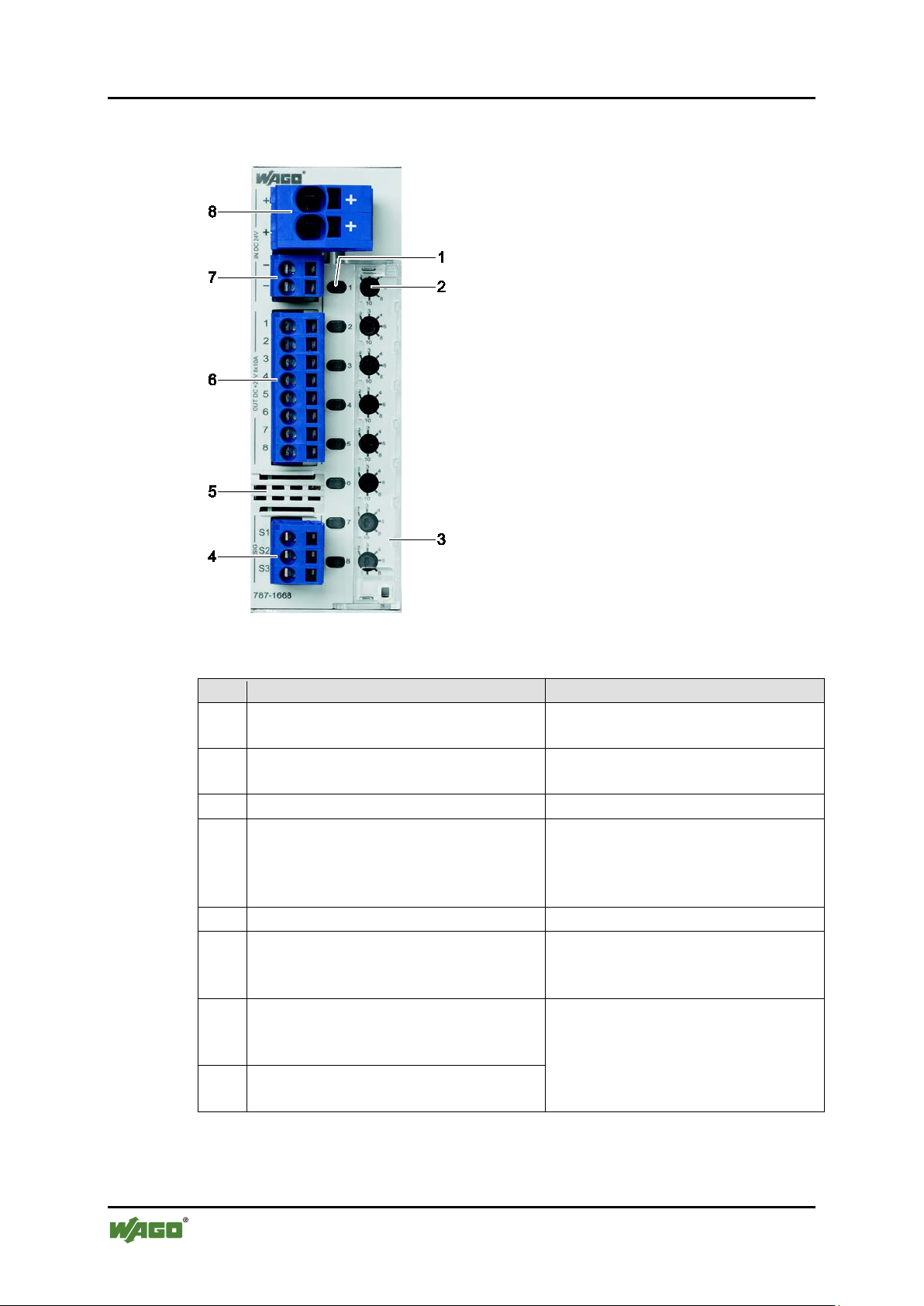
Table 5: Key for "Device view" figure
No.
Designation
Reference
1
Switch
"Device Description" >
"Operating Elements" > "Buttons"
2
Rotary switch
"Device Description " > "Operat i n g
Elements" > "Rotary Switches"
3
Cover, sealable *)
4
CAGE CLAMP® connections
"Function Description" >
"Signaling Output S3"
5
Marking field **)
6
CAGE CLAMP® connections
"Device Description" >
"Fuse-Protected Output Channels"
7
CAGE CLAMP® connections
(for internal supply only)
8
CAGE CLAMP® connections
for 24 V input voltage
*) can also be marked using TOPJOB®S marker strips (Item No. 2009-110)
**) can be marked using TOPJOB®S marker strips (Item No. 2009-110) or
787-1668 Electronic Circuit Breaker
Pos: 20 /All e Serien ( Allgemei ne Module)/Ü berschri ften für al le Serie n/Geräteb eschreibung /Ansicht - Ü berschrif t 2 @ 4\mod_1240984217343_21.docx @ 31958 @ 2 @ 1
3.1 View
Pos: 21 /Ser ie 787 (E PS ITRON)/Ger ätebesc hr ei bung/Ans i ch t /A nsicht 787- 1668 @ 13\mod_1343371041650_21.docx @ 101060 @ @ 1
Figure 1: View of device
Control input S1 and
Signaling outputs S2 and S3
for fuse-protected output channels
for 0 V reference potential
"Control Input S1"/
"Signaling Output S2"/
"Connections" >
"Device Descripti on " >
"Connections" > "Power Supply"
WMB Multi marking system
Pos: 22 /Dokum e nt ation allge mei n/Glieder ungselem e nte/---Seiten wechsel--- @ 3\mod_1221108045078_0.docx @ 218 10 @ @ 1
Manual
Version 1.1.0
Page 15
EPSITRON® Device Description 15
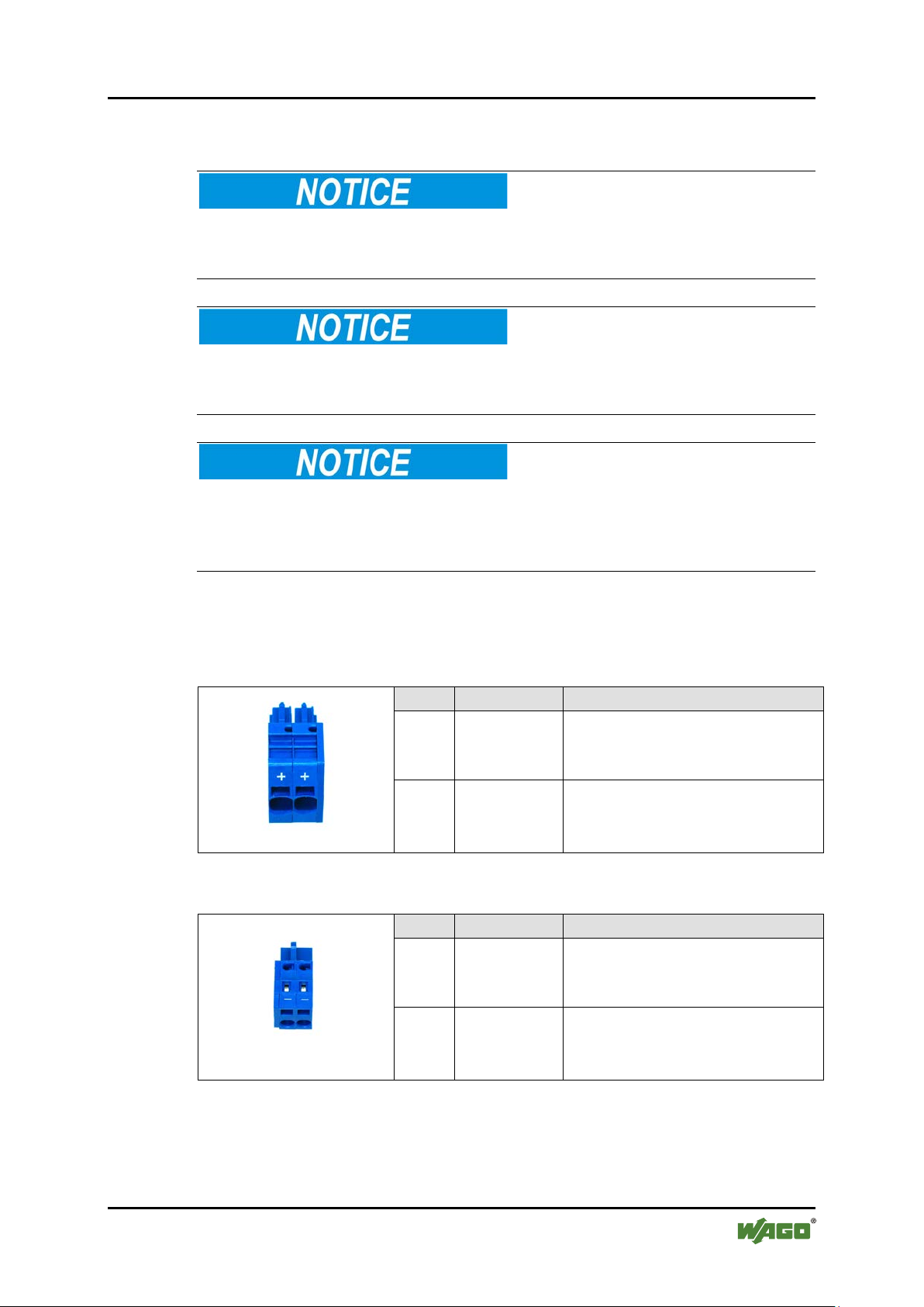
Table 6: Power supply connections
Figure 2: 24 V input
No.
Designation
Function
1 + 24 V input voltage
2 + 24 V input voltage
Table 7: Power supply connections
Figure 3: 0 V input
No.
Designation
Function
1 - Reference potential 0 V
2 - Reference potential 0 V
787-1668 Electronic Circuit Breaker
Pos: 23 /All e Serien ( Allgemei ne Module)/Ü berschri ften für al le Serie n/Geräteb eschreibung /Anschlü sse - Übersc hrift 2 @ 4\mod_1240984262656_21.docx @ 31961 @ 2 @ 1
3.2 Connectors
Pos: 24.1 /S erie 787 ( EPSITRON) /Wichtige Erläuteru ngen/Sich erheits- u nd sonstig e Hinweis e/Achtung/ Achtung: F ederleist en nicht u nter Last s tecken od er ziehen! @ 18\mod_1392900217463_21.docx @ 145941 @ @ 1
Do not plug in or disconnect the female connector while a load is applied!
Only plug in or disconnect the female connectors when the device is not live!
Failure to observe this can result in damage to the contacts due to arcing!
Pos: 24.2 /Serie 787 (EPSITRON)/ Wichtige Erläuteru ngen/Sich erheits- und sonstige H inweise/ Achtung/ Achtung: F ederleist en bis zum Anschlag i n die Stif tleisten s tecken! @ 18\mod_1392902889021_21.docx @ 145944 @ @ 1
Plug the female connectors all the way into the male connectors!
Always plug the female connectors all the way in to the male connectors. This
ensures proper contact at all times.
Pos: 24.3 /S erie 787 ( EPSITRON) /Wichtige Erläuteru ngen/Sich erheits- u nd sonstig e Hinweis e/Achtung/ Achtung: Fr eischwing ende Leit erenden durch eine g eeignet e Zugentlas tung abf angen! @ 1 8\mod_1392904262758_21.docx @ 146008 @ @ 1
Attach the free ends of the conductors using a strain relief device!
Provide appropriate strain relief means to attach and cap any free ends of the
conductors. Female connectors can be pulled out of the male connectors by high
vibration levels or shock impacts.
Pos: 24.4 /Dokumentation allgemein/Glieder ungselemente/------Leerzeile------ @ 3\mod_1224662755687_0.do cx @ 24460 @ @ 1
Pos: 24.5 /Serie 787 ( E PSITRON)/ Gerätebes c hreibung/ Anschlüss e/Anschl üss e 787-166x - Versorgung @ 13\mod_1345543912608_21.docx @ 101785 @ 3 @ 1
3.2.1 Power supply
Pos: 24.6 /S erie 787 ( EPSITRON) /Wichtige Erläuteru ngen/Sich erheits- u nd sonstig e Hinweis e/Achtung/ Achtung: Gesamtstro m auf zwei Eingang sklemmen a ufteilen! @ 18\mod_1392893598736_21.docx @ 145938 @ @ 1
Manual
Version 1.1.0
Page 16

16 Device Description EPSITRON®
Table 8: Connections – Fuse-protected outputs
outputs Ch1 … Ch8
No.
Designation
Function
1 … 8
Ch1 … Ch8
Fuse-protected outputs
Table 9: Connections – Control and signaling contacts
signaling contacts
No.
Designation
Function
1
S1
Control Input S1
2
S2
Signal Output S2
3
S3
Signal Output S3
787-1668 Electronic Circuit Breaker
Total current exceeds 40 A!
Distribute the current to input terminals "IN1" and "IN2" when the total current
should exceed 40°A, as otherwise the plug-in connectors will become overheated
and can be damaged or destroyed.
Pos: 24.7 /S erie 787 ( EPSITRON) /Geräteb eschreibung /Anschl üsse/Anschl üsse 787- 1668 - Abgesichert e Aus g ä ng e @ 12\mod_1342099465661_21.docx @ 100030 @ 3 @ 1
3.2.2 Fuse-Protected Outputs
Figure 4: Fuse-protected
Pos: 24.8 /S erie 787 ( EPSITRON) /Geräteb eschreibung /Anschl üsse/Anschl üsse 787- 166x - Steuer- und Signalkontakte @ 13\mod_1345544033477_21.doc x @ 101808 @ 3 @ 1
3.2.3 Control and Signaling Cont a c t s
Ch1 … Ch8
Pos: 25 /Dokum e nt ation allge mei n/Glieder ungselem e nte/---Seiten wechsel--- @ 3\mod_1221108045078_0.docx @ 218 10 @ @ 1
Manual
Version 1.1.0
Figure 5: Control and
Page 17

EPSITRON® Device Description 17
Table 10: Legend for "Indicato rs" figure
LED
Button color
Explanation
Green
Output channel activated
Red
Output channel
deactivated
Red, flashing
Wait for temperature to
period)
787-1668 Electronic Circuit Breaker
Pos: 26 /All e Serien ( Allgemei ne Module)/Ü berschri ften für al le Serie n/Geräteb eschreibung /Anzeigeel emente - Überschri ft 2 @ 4\ mod_1240984390875_21.docx @ 31964 @ 2 @ 1
3.3 Display Elements
Pos: 27 /Ser ie 787 (E PSITRON)/ Gerätebesc hreibung/ Anzeigeel emente/A nzeigeele mente 787- 1668 @ 13\mod_1343380073501_21.docx @ 101066 @ @ 1
A multi-colored LED, integrated in a button, is assigned to each output channel.
This LED indicates the current operating status of the output channel.
Figure 6: Indicato rs
1 … 8
Further signaling possible!
Other statuses can also be indicated if an error occurs. For information about this,
refer to the "Operating Statuses, Signaling, Reactions" table given in this manual.
Pos: 28 /Dokum e nt ation allge mei n/Glieder ungselem e nte/---Seiten wechsel--- @ 3\mod_1221108045078_0.docx @ 218 10 @ @ 1
return to normal (cooling
Manual
Version 1.1.0
Page 18

18 Device Description EPSITRON®
787-1668 Electronic Circuit Breaker
Pos: 29 /All e Serien ( Allgemei ne Module)/Ü berschri ften für al le Serie n/Geräteb eschreibung /Bedienel emente - Ü berschrif t 2 @ 4\mod_1239191655456_21. docx @ 30 439 @ 2 @ 1
3.4 Operating Elements
Pos: 30 /Ser ie 787 (E PSITRON)/ Gerätebesc hreibung/ Bedienele mente/Be dieneleme nte 787-1668 @ 12\mod_1341816912585_21.doc x @ 99130 @ 33 @ 1
3.4.1 Buttons
A button is assigned to each output channel. Depending on the operating mode the
button can have two different functions:
• During operation, the channel can be activated and de-activated.
• If an error is present, the channel can be reset.
Figure 7: Buttons
Manual
Version 1.1.0
Page 19

EPSITRON® Device Description 19
Table 11: Rotary Switch Settings
Variant
Setting
787-1668
2 A
3 A
4 A
6 A
8 A
10 A
787-1668/0106-0000
1 A
2 A
3 A
4 A
5 A
6 A
787-1668/0006-1000
0.5 A
1 A
2 A
3 A
4 A
6 A
787-1668 Electronic Circuit Breaker
3.4.2 Rotary Switch
A rotary switch, which can be used to set the output currents for the individual
outputs, is assigned to each output channel. The following settings are possible:
Figure 8: Rotary Switch
Observe trip curve!
Observe the trip curve given in the Section "Function Description" when setting
the individual output channels.
Pos: 31 /Dokum e nt ation allge mei n/Glieder ungselem e nte/---Seiten wechsel--- @ 3\mod_1221108045078_0.docx @ 218 10 @ @ 1
Manual
Version 1.1.0
Page 20

20 Device Description EPSITRON®
Table 12: Device data
Width
42 mm
Height
127 mm
Depth (from upper edge of DIN 35 rail)
142.5 mm
Weight
440 g
787-1668 Electronic Circuit Breaker
Pos: 32 /All e Serien ( Allgemei ne Module)/Ü berschri ften für al le Serie n/Geräteb eschreibung /Technisc he Daten - Ü berschrif t 2 @ 3\mod_1232967587687_21.docx @ 26 924 @ 2 @ 1
3.5 Technical Data
Pos: 33 /Ser ie 787 (E PSITRON)/ Gerätebesc hreibung/T echnisch e Daten/T echnische Daten 787- 1668 @ 12\mod_1341822484504_21.docx @ 9913 3 @ 33333 @ 1
3.5.1 Device Data
Manual
Version 1.1.0
Page 21

EPSITRON® Device Description 21
Table 13: Technical data - "Input"
Nominal input voltage
24 VDC
Input voltage range
18 ... 30 VDC
Maximum residual ripple/
ripple for the input voltage
3 % with resistive load
Required input voltage at which the
threshold)
20 V
Input voltage at which the output
threshold)
18 V
Maximum continuous current for the
787-1668/0006-1000:
48 A
Maximum continuous current per I/O
module pole
40 A
Overvoltage protection
Suppressor diodes (33 V)
Zero-signal current for open-circuit
787-1668/0006-1000:
48 mA
Power dissipation for open-circuit
787-1668/0006-1000:
1.15 W
Input modules
WAGO-MULTI CONNECTION
ferrule)
787-1668 Electronic Circuit Breaker
3.5.2 Technical Data for "Input"
output channels are activated (activation
channels are de-activated (trip
device
operation at 24 V
operation at 24 V
787-1668:
787-1668/0106-0000,
787-1668,
787-1668/0106-0000:
787-1668,
787-1668/0106-0000:
70 A
55 mA
1.32 W
Manual
Version 1.1.0
SYSTEM (MCS), 721 Series
Connection: 0.08 mm² … 2.5 mm²
(maximum 1.5 mm² with insulated
ferrule)
WAGO-MULTI CONNECTION
SYSTEM (MCS), 831 Series
Connection: 0.5 mm² … 10 mm²
(maximum 6 mm² with insulated
Page 22

22 Device Description EPSITRON®
Table 14: Technical data - "Output"
Nominal output voltage
8 x 24 VDC
Output nominal current (adjustable)
787-1668/0006-1000:
0.5 A, 1 A, 2 A, 3 A, 4 A, 6 A
Voltage drop between input and output
787-1668/0006-1000:
155 mV with maximum output current
Device initialization time
250 ms
Waiting period after an output channel
787-1668/0006-1000:
500 ms (short circuit), 10 s (overload)
Total power dissipation for output
787-1668/0006-1000:
8.6 W with maximum output current
Efficiency
99 %
Maximum load capacity per output
787-1668/0006-1000:
greater than 65 … 620 mF
Integrated fusing per output channel
15 A, slow
ON delay
Based on load:
minimum 50 ms, maximum 5 s
Recovery stability
maximum 35 V
Parallel connection of output channels
prohibited
Series connection of output channels
prohibited
Output terminals
WAGO-MULTI CONNECTION
ferrule)
787-1668 Electronic Circuit Breaker
3.5.3 Technical Data for "Output"
787-1668:
787-1668/0106-0000:
787-1668:
787-1668/0106-0000:
has been de-activated (cooling time)
787-1668,
787-1668/0106-0000:
current 8 x 10 A
787-1668:
787-1668/0106-0000:
2 A, 3 A, 4 A, 6 A, 8 A, 10 A
1 A, 2 A, 3 A, 4 A, 5 A, 6 A
200 mV with maximum output current
120 mV with maximum output current
500 ms (short circuit), 20 s (overload)
20 W with maximum output current
8.0 W with maximum output current
channel
Manual
Version 1.1.0
787-1668/0106-0000:
787-1668,
greater than 50 … 500 mF
SYSTEM (MCS), 721 Series
Connection: 0.08 mm² … 2.5 mm²
(maximum 1.5 mm² with insulated
Page 23

EPSITRON® Device Description 23
Table 15: Technical data - "Ambient condition s"
Ambient temperature range
-25 °C … +70 °C
Derating
787-1668/0006-1000:
no derating
Requisite minimum spacing
(top/bottom)
40 mm
Requisite minimum spacing
(lateral)
0 mm
Table 16: Technical data - "Signaling"
LED
green/red/orange (per output channel)
Control Input S1
non electrically isolated 24 VDC input
(low level): minimum 200 ms
Signal Output S2
24 VDC, active high, short-circuit proof
25 mA
Signal Output S3
24 VDC, active high, short-circuit proof
25 mA
Control and Signaling Terminals
WAGO-MULTI CONNECTION
ferrule)
787-1668 Electronic Circuit Breaker
3.5.4 Technical Data for "Ambient condi t ions "
787-1668:
787-1668/0106-0000,
3.5.5 Technical Data for "Signali ng"
Maximum 10 A per output channel
Total output current
(all output channels)
50 A ≥ 60 °C,
40 A = 70 °C.
(relative to the module 0 V input)
Voltage level "active high":
minimum 15 V, maximum 30 V
Voltage level "active low":
minimum 0 V, maximum 5 V
Jitter for pulse pattern: ±5 % or ±5 ms;
with the higher value applying.
Waiting period after pulse sequence
(S1, S2, S3)
Pos: 34 /Dokum e nt ation allge mei n/Glieder ungselem e nte/---Seiten wechsel--- @ 3\mod_1221108045078_0.docx @ 218 10 @ @ 1
Manual
Version 1.1.0
maximum current carrying capacity:
maximum current carrying capacity:
SYSTEM (MCS), 721 Series
Connection: 0.08 mm² … 2.5 mm²
(maximum 1.5 mm² with insulated
Page 24

24 Device Description EPSITRON®
Conformity Marking
Conformity Marking
787-1668 Electronic Circuit Breaker
Pos: 35 /All e Serien ( Allgemei ne Module)/Ü berschri ften für al le Serie n/Geräteb eschreibung /Zulassu ngen - Übers c hrift 2 @ 3\mod_1224055364109_21.docx @ 24030 @ 2 @ 1
3.6 Approvals
Pos: 36.1 /Seri e 78 7 (E PSITRON)/ Gerätebesc hreibung /Z ulassung e n/Z ulassung e n El e ktr. Schutz sc halter 787- xxxx Allgem ei n , St andardver s . un d s p ez i f . Var i a nt e - Einl. @ 13\mod_1347451782755_21.docx @ 102663 @ @ 1
The following approvals have been granted for the standard version of the
electronic circuit breaker 787-1668 and version 787-1668/0106-0000:
Pos: 36.2 /Al le Seri en (Allgemei ne Modul e)/Zulassu ngen/Stan dardzulas sungen/C E (Konformi tätskennz eichnung) @ 3\mod_1224494777421_21.docx @ 24 276 @ @ 1
Pos: 36.3 /Al le Seri en (Allgemei ne Modul e)/Zulassu ngen/Stan dardzulas sungen/cU Lus (UL508) @ 3\mod_1224055013140_0.docx @ 24020 @ @ 1
Pos: 36.4 /Al le Seri en (Allgemei ne Modul e)/Zulassu ngen/Stan dardzulas sungen/U L2367 @ 18\ mod_139141997931 8_0.docx @ 144214 @ @ 1
Pos: 36.5 /Al le Seri en (Allgemei ne Modul e)/Zulassu ngen/Schi ffszulass ungen/GL ( Germanisc her Lloyd) Cat. C ( EMC 2) @ 18\mod_1392645436824_0.docx @ 145658 @ @ 1
Pos: 36.6 /Dokumentation allgemein/Glieder ungselemente/------Leerzeile------ @ 3\mod_1224662755687_0.do cx @ 24460 @ @ 1
Pos: 36.7 /Seri e 78 7 (E PSITRON)/ Gerätebesc hreibung /Z ulassung e n/Z ulassung e n El e ktr. Schutz sc halter 787- xxxx Allgemein, spezif. Variante - Ei nl. @ 18\mod_1391088086008_21.docx @ 144056 @ @ 1
The following approvals have been granted for the version 787-1668/0006-1000
of the electronic circuit breaker 787-1668:
Pos: 36.8 /Al le Seri en (Allgemei ne Modul e)/Zulassu ngen/Stan dardzulas sungen/C E (Konformi tätskennz eichnung) @ 3\mod_1224494777421_21.doc x @ 24276 @ @ 1
Pos: 36.9 /Al le Seri en (Allgemei ne Modul e)/Zulassu ngen/Schi ffszulass ungen/GL ( Germanisc her Lloyd) Cat. C ( EMC 2) @ 1 8\mod_1392645436824_0.docx @ 145658 @ @ 1
Pos: 36.10 /D okument ation allge mein/Gli ederungsel emente/------Leer zeile------ @ 3\mod_1224662755687_0.docx @ 24460 @ @ 1
Pos: 36.11 /Ser i e 7 87 ( E P SIT R ON)/Gerä t e b es c hreibung/ Zul assungen /Zul. in Vorb . E le ktr. Schutz sc h al t er 787-xxxx Allgem ein, spezif. Variante - Einl. @ 18\mod_1391088393401_21.docx @ 144 064 @ @ 1
The following approvals are pending for the version 787-1668/0006-1000 of the
electronic circuit breaker 787-1668:
Pos: 36.12 / Alle Seri en (Allgem eine Modul e)/Zulass ungen/Sta ndardzulas sungen/cU Lus (UL50 8) @ 3\mod_1224055013140_0.docx @ 24020 @ @ 1
Pos: 36.13 / Alle Seri en (Allgem eine Modul e)/Zulass ungen/Sta ndardzulas sungen/U L2367 @ 18 \mod_1391419979318_0.docx @ 144214 @ @ 1
CULUS
UL508
UR UL2367
GL (Germanischer Lloyd) Cat. C (EMC 2)
GL (Germanischer Lloyd) Cat. C (EMC 2)
CULUS
UL508
UR UL2367
Pos: 37 /Dokum e nt ation allge mei n/Glieder ungselem e nte/---Seiten wechsel--- @ 3\mod_1221108045078_0.docx @ 218 10 @ @ 1
Manual
Version 1.1.0
Page 25

EPSITRON® Device Description 25
Information technology
equipment
Safety
Part 1: General requirements
DIN EN 60950-1:2006 +
A11:2009 + A1:2010 + A12:2012
Electromagnetic compatibility
(EMC)
Part 6
Immunity for industrial environments
DIN EN 61000-6-2:2005
Electromagnetic compatibility
(EMC)
Part 6
Emission standard for residential,
commercial and light
environments
DIN EN 61000-6-3:2007 + A1:2011
787-1668 Electronic Circuit Breaker
Pos: 38 /All e Serien ( Allgemei ne Module)/Ü berschri ften für al le Serie n/Geräteb eschreibung /Normen u nd Richtli nien - Über sc hrift 2 @ 4\mod _1242804031875_21.docx @ 33646 @ 2 @ 1
3.7 Standards and Guidelines
Pos: 39.1 /S erie 787 ( EPSITRON) /Geräteb eschreibung /Normen und Richtli nien/Nor men und Ric htlinie n Elektroni scher Sch utzschalter 78 7-xxxx, ohne Variant enangabe - Einleitu ng @ 13\mod_1347452665951_21.docx @ 102670 @ @ 1
The 787-1668 electronic circuit breaker is in compliance with the following
standards and guidelines:
Pos: 39.2 /Al le Seri en (Allgemei ne Modul e)/Normen und Richtli nien/St andardnor men/EG-Nied erspannu ngsrichtli nie 2006/ 9 5/EG-Nied erspannu ngsrichtli nie 2006/ 9 5/ EG @ 7 \mod_1274262383272_21.docx @ 56632 @ @ 1
EC Low Voltage directive (LVD) 2006/95/EC
Pos: 39.3 /All e Serien ( Allgemei ne Module)/ Normen un d Richtli nien/EMV-N ormen - St andard/EG- EMV-Richtlini e 2004/10 8/ E G-EM V-Richtlinie 2004/108/EG @ 7\mod_1274262373820_21.docx @ 56628 @ @ 1
EC EMC Directive 2004/108/EC
Pos: 39.4 /Al le Seri en (Allgemei ne Modul e)/Normen un d Ri c htlinien/ Sicherheit s normen/ Si ch er heit: DIN EN 60 9 50-1:2006 + A11:2009 + A1:2010 + A12: 2012 (Ergänzung mit "und") @ 18\mod_1391077570696_21.docx @ 143968 @ @ 1
–
–
Pos: 39.5 /Al le Seri en (Allgemei ne Modul e)/Normen und Richtli nien/Sic herheitsn ormen/Sic herheit: D IN EN 610 00-6-2:2005 @ 18 \ mod_1391172357008_21.docx @ 144102 @ @ 1
–
-2: Generic standards –
Pos: 39.6 /Al le Seri en (Allgemei ne Modul e)/Normen und Richtli nien/Sic herheitsn ormen/Sic herheit: D IN EN 610 00-6-3:2007 + A1:2011 (Ergän zung mit "und") @ 18\mod_1391173469051_21.docx @ 144166 @ @ 1
–
-3: Generic standards –
Pos: 40 /Dokum e nt ation allge mei n/Glieder ungselem e nte/---Seiten wechsel--- @ 3\mod_1221108045078_0.docx @ 218 10 @ @ 1
-industrial
Manual
Version 1.1.0
Page 26

26 Mounting EPSITRON®
787-1668 Electronic Circuit Breaker
Pos: 41 /All e Serien ( Allgemei ne Module)/Ü berschri ften für al le Serie n/Montiere n - Demonti eren/Monti eren - Übers c hrift 1 @ 3\mod_1225446744750_21.docx @ 24900 @ 1 @ 1
4 Mounting
Pos: 42 /Ser ie 787 (E PSITRON)/M ontieren /Montage 7 87-16xx @ 11\mod_1317296048899_21.docx @ 80170 @ 22 @ 1
4.1 Mounting
Pos: 59 /Ser ie 787 (E PSITRON)/M ontieren /Montage 7 87-xxxx @ 11\mod_1317296048899_6.docx @ 80169 @ 22 @ 1
The device is designed for mounting on a DIN 35 rail.
4.2 Mounting the Device on the DIN 35 Rail
Figure 9: Mounting the device on t he DIN 35 rail
1. Tilt the device slightly.
2. Place the device with its DIN rail guide on the top edge of the DIN rail.
3. Slide the device all the way down.
Figure 10: Mo unt ing the device on the DI N 35 rail
4. Press it down against the bottom fastener until you hear it lock into place.
5. Lightly shake the device to ensure that it is correctly locked into place.
Manual
Version 1.1.0
Page 27

EPSITRON® Mounting 27
787-1668 Electronic Circuit Breaker
4.3 Removing the Device from the DIN 35 Rail
Figure 11: Removing the device from the DIN 35 rail
1. Use a screwdriver to press down on the locking tab.
Figure 12: Removing the device from the DIN 35 rail
2. Pull the device out at the bottom edge of the DIN 35 rail.
Pos: 43 /Dokum e nt ation allge mei n/Glieder ungselem e nte/---Seiten wechsel--- @ 3\mod_1221108045078_0.docx @ 218 10 @ @ 1
Manual
Version 1.1.0
Page 28

28 Connect Devices EPSITRON®
787-1668 Electronic Circuit Breaker
Pos: 44 /All e Serien ( Allgemei ne Module)/Ü berschri ften für al le Serie n/Anschließ en/Gerät e anschlie ßen - Übers chrift 1 @ 3\mod_1234172889468_21.docx @ 27460 @ 1 @ 1
5 Connect Devices
Pos: 45 /All e Serien ( Allgemei ne Module)/Ü berschri ften für all e S er i e n/ A ns c hl i eß en/Anschl ussbeis piel - Überschr i ft 2 @ 4\ mod_1242621672468_21.docx @ 33293 @ 2 @ 1
5.1 Connection Example
Pos: 46 /Ser ie 787 (E PSITRON)/ Anschließ en/Anschlus sbeispi el 787-1668 @ 13\mod_1343377823951_21.docx @ 101063 @ @ 1
Figure 13: Conne ction exa mple
Pos: 47 /Dokum e nt ation allge mei n/Glieder ungselem e nte/---Seiten wechsel--- @ 3\mod_1221108045078_0.docx @ 218 10 @ @ 1
Manual
Version 1.1.0
Page 29

EPSITRON® Function Description 29
787-1668 Electronic Circuit Breaker
Pos: 48 /All e Serien ( Allgemei ne Module)/Ü berschri ften für al le Serie n/Funktions beschrei bung - Über schrift 1 @ 4\mod_1239025975389_21.docx @ 30003 @ 1 @ 1
6 Function Description
Pos: 49 /Ser ie 787 (E PSITRON)/F unktions beschreibu ng/Unter- und Überspannungser kennung 787-166x @ 13\mod_1343392113095_21.docx @ 101122 @ 2 @ 1
6.1 Undervoltage and Overvoltage Detection
This device operates in a voltage range between 18 … 30 VDC.
Pos: 50 /Serie 7 87 (EPSITRON)/F unktionsb eschreibu ng/Auslöse kennlinie 787-166x @ 13\mod_1343389182679_21.docx @ 101119 @ 233345554 @ 1
6.2 Trip Curves
6.2.1 Trip Curve for the 10 A Circuit Breaker 787-1668
Figure 14: Trip Curve for the 10 A Circuit Breaker 787-1668
Manual
Version 1.1.0
Page 30

30 Function Description EPSITRON®
787-1668 Electronic Circuit Breaker
6.2.2 Trip Curve for the 6 A Circuit Breaker 787-1668/0106-0000
Figure 15: Trip Curve for the 6 A Circuit Breaker 787-1668/0106-0000
6.2.3 Trip Curve for the 6 A Circuit Break er w it h Active Current Limitation 787-1668/0006-1000
Figure 16: Trip Curve for the 6 A Circuit Breaker with Active Current Li mitation
787-1668/0006-1000
Manual
Version 1.1.0
Page 31

EPSITRON® Function Description 31
Shutdown takes place
after 5 seconds,
with an over-current greater than
within 50 milliseconds … 5 seconds,
with an over-current between
(Threshold 1)
(Threshold 2)
(Threshold 3)
0.5 A
0.75 A
1.00 A
1.20 A
1 A
1.20 A
1.50 A
1.70 A
2 A
2.20 A
3.00 A
3.40 A
3 A
3.30 A
4.50 A
5.10 A
4 A
4.40 A
6.00 A
6.80 A
6 A
6.60 A
8.00 A
10.2 A
787-1668 Electronic Circuit Breaker
6.2.3.1 Response of the Electronic Circuit Breaker with Active Current Limitation
Nominal
current
The function is activated when
• an over-current measured at an output is greater than the corresponding
threshold for the set nominal current (Threshold 1).
• the measured over-current is present for more than 0.1 ms.
The activated circuit breaker can respond in one of three ways:
1. An over-current is present that is greater than Threshold 3
2. An over-current is present that is greater than Threshold 1,
but less than Threshold 2
3. An over-current is present that is greater than the nominal current, but less
than Threshold 1
Manual
Version 1.1.0
Page 32

32 Function Description EPSITRON®
787-1668 Electronic Circuit Breaker
6.2.3.1.1 Response 1: Over-current present that is greater than Threshold 3
If an over-current is present that is greater than Threshold 3, the current will be
limited to a value situated between Threshold 2 and Threshold 3. This limitation is
effective for at least 50 ms and functions as a variable series resistor. The output
voltage is less than the input voltage.
If the over-current does not decrease, the output concerned will be deactivated
within a period of 50 ms … 5 s.
6.2.3.1.2 Response 2: Over-current present that is greater than Threshold 1, but less than Threshold 2
If an over-current is present that is greater than Threshold 1, but less than
Threshold 2, the output will be deactivated after 5 s.
6.2.3.1.3 Response 3: Over-current present that is greater than the nominal current, but less than Threshold 1
If an over-current is present that is greater than the nominal current, but less than
Threshold 1, the output is not deactivated. This over-current is report, however.
6.2.3.2 Selectiv e immediat e d eact ivation
If the output voltage from the power supply unit drops below 20 V, all outputs
with current greater than the set nominal current are deactivated within 16 ms.
Pos: 51 /Dokum e nt ation allge mei n/Glieder ungselem e nte/---Seiten wechsel--- @ 3\mod_1221108045078_0.docx @ 218 10 @ @ 1
Manual
Version 1.1.0
Page 33

EPSITRON® Function Description 33
Table 17: Standard reference values for 787-1668 and 787-1668/0106-0000
Line lengths
lines
Making capacity
0.75 mm2 *
Making capacity
1.5 mm2 *
Making capacity
2.5 mm2 *
0
48,000
48,000
48,000
2.5
61,500
70,000
63,300
5.0
83,300
50,000
73,300
10.0
130,000
53,300
73,300
20.0
> 620,000
81,300
63,300
40.0
> 620,000
222,800
91,500
* Capacities determined with a base load of 10 A/6 A at the output channel.
Table 18: Standard reference values for 787-1668/0006-1000
Line lengths
lines
Making capacity
0.75 mm2 *
Making capacity
1.5 mm2 *
Making capacity
2.5 mm2 *
0
74,300
64,800
64,800
2.5
72,000
69,300
67,800
5.0
78,000
78,300
69,300
10.0
96,800
86,800
71,100
20.0
145,200
102,500
86,800
40.0
> 620,000
152,500
107,800
* Capacities determined with a base load of 6 A at the output channel.
787-1668 Electronic Circuit Breaker
Pos: 52 /Ser ie 787 (E PS ITRON)/F u n kti onsbeschr ei bung/Eins c halten von k ap az i ti ven Lasten 7 87- 166x @ 12\mod_1341401971175_21.docx @ 98843 @ 233 @ 1
6.3 Activating Capacitive Loads
High capacitive loads can be applied using the electronic circuit breaker. The
power supply unit providing power to the device must be capable of supplying a
voltage of at least 18 VDC, even at the maximum required current. The required
current can be set using the rotary switch.
The tables below gives some standard reference values determined in experiments
with 24 VDC input voltage:
6.3.1 Reference Values for 787-1668 and 787-1668/0106-0000
(m) for feed
and return
(µF) with a wire
cross section of
(µF) with a wire
cross section of
6.3.2 Reference Values for 787-1668/0006-1000
(m) for feed
and return
(µF) with a wire
cross section of
(µF) with a wire
cross section of
(µF) with a wire
cross section of
(µF) with a wire
cross section of
Pos: 53 /Ser ie 787 (E PSITRON)/F unktions beschreibu ng/Betri ebszustän de, Signali sierung, R eaktione n 787-166x @ 12\mod_1341474059753_21. docx @ 98960 @ 2 @ 1
Manual
Version 1.1.0
Page 34

34 Function Description EPSITRON®
Table 19: Operating statuses, signaling, rea c tions
Status
Operating status
Channel
LED
Signal output
S3 (common
signal)
Button is
to …
Control input S1
0
Device
initialization. 1
off
off
0 V - -
1
Output activated,
function OK.
on
Green
24 V
Status 3
Status 3
(via bit pattern)
2
Output curr ent
nominal current. 2
on
Green
24 V
Status 3
Status 3
3
Output de-
control input S1. 3
off
Red
24 V
Status 1
Status 1
4
Output de-
period is active. 4
off
Red
0 V - -
5
Output de-
completed. 5
off
Orange
0 V
Status 3
Status 1
6
Device error:
detected.
off
Red
rapid
0 V
Status 6
-
1
The outputs are re-activated based on the load applied as soon as device initialization is
concluded.
2
The output i s de-activated automatically in accordance with the given trip curve. The
device then switches to Status 4.
3
The status i s saved when the device i s switched off.
4
After a defined waiting period ( c ooling time), the output switches to Status 5. The
elements a gainst any ove rloading.
5
The output can be re-activated as follows:
The device then switches to Status 1.
787-1668 Electronic Circuit Breaker
6.4 Operating Statuses, Signaling, Reactions
greater than
activated
manually, or by
activated due to
excessive current.
Cooling (waiting)
activated due to
excessive current.
Cooling (waiting)
period is
flashing
flashing
flashing
pressed
Transition
Transition
to …
(via bit pattern)
(via bit pattern)
(using pulse
longer than 0.5 s)
Defective fuse
flashing,
remaining time of the waiting period is saved when the device is switched off. This time
must first elapse when the device is s witched on again. This feature protects the switching
• by pressing the associated button twice, or
• by applying a pulse at control input S1.
Manual
Version 1.1.0
Page 35

EPSITRON® Function Description 35
787-1668 Electronic Circuit Breaker
Abbildung 17: Operating Statuses, Signaling, Reactions
Pos: 54 /Dokum e nt ation allge mei n/Glieder ungselem e nte/---Seiten wechsel--- @ 3\mod_1221108045078_0.docx @ 218 10 @ @ 1
Manual
Version 1.1.0
Page 36

36 Function Description EPSITRON®
787-1668 Electronic Circuit Breaker
Pos: 55 /Ser ie 787 (E PSITRON)/F unktions beschreibu ng/Zuschal tverzöger ung 787-166x @ 12\mod_1341479703716_21.docx @ 98963 @ 2 @ 1
6.5 ON Delay for Specific Channels
The outputs are activated in a staggered manner in the order of their channel
numbers as soon as a minimum input voltage is present. Outputs which have been
de-activated manually, or by a reset signal, are skipped in this process.
The time at which the next output in the sequence is activated is based on the
following conditions:
• At least 50 ms must elapse after activation of the previous output.
• The output current of the previously activated output must lie below the
nominal value set for the output.
Pos: 56 /Dokum e nt ation allge mei n/Glieder ungselem e nte/---Seiten wechsel--- @ 3\mod_1221108045078_0.docx @ 218 10 @ @ 1
Manual
Version 1.1.0
Page 37

EPSITRON® Function Description 37
787-1668 Electronic Circuit Breaker
Pos: 57 /Ser ie 787 (E PSITRON)/F unktions beschreibu ng/Digital eingang S1 787-1668 @ 12\mod_1341908222413_21.docx @ 99460 @ 233 @ 1
6.6 Control Input S1
A signal between S1 and 0 V has the effect that
• all channels previously de-activated due to overloading can now be re-
activated.
• specific channels can be activated or de-activated.
6.6.1 Re-activating Tripped Channels
Apply a signal for at least 0.5 seconds. All channels previously de-activated due
to overloading are then re-activated in sequential order, based on the load applied.
Figure 18: Example of re -activation via control input S1, or signal output S3.
Manual
Version 1.1.0
Page 38

38 Function Description EPSITRON®
Table 20: Bit Allocation for Control Input S1
Bit
Output
channel
Byte
Function
1
START bit, value = "0"
2
Channel 8
3
Channel 7
4
Channel 6
5
Channel 5
6
Channel 4
7
Channel 3
8
Channel 2
9
Channel 1
10 Command
status"
"1" = The required switching statuses of the
output channels (Byte 1) are ignored.
11
Command
length"
"1" = The extended 89-bit protocol is being
"0" = The short 17-bit protocol is being used.
787-1668 Electronic Circuit Breaker
6.6.2 Specific Activation and De -ac t ivation of Non-Tripped Output Channels
A coded pulse pattern must be present to activate and de-activate specific output
channels. The encoded pulse pattern can consist of
• 17 bits or
• 89 bits (with Firmware 2.0 and higher),
which must be transmitted as "Manchester code" (based on IEEE 802.3). Here, a
falling clock pulse denotes a logical zero ("0"), and a rising clock pulse a logical
one ("1").
The first bit to be transmitted has the value "0" and serves as the start bit, after
which either 16-bit or 88-bit user data is transmitted.
No separate pulse signal is applied; the electronic circuit breaker obtains the pulse
signal from the pulse pattern that is received. The circuit breaker is then
synchronized automatically and transmits the current status back via signal output
S2.
The table below provides an overview of the functions for the individual data bits:
Required switching statuses of output channels
"1" = The corresponding output channel is
Byte 1
activated.
"0" = The corresponding output channel is
deactivated.
bit
"switching
output channels (Byte 1) are accepted.
"0" = The required switching statuses of the
Byte 2
bit
"protocol
used; the circuit breaker is transferring
additional user data.*
Manual
Version 1.1.0
Page 39

EPSITRON® Function Description 39
12
Command
"1" = The momentary input voltage and the
transferred.**
13
14 15 16 17 18 … 25
Byte 3
26 … 33
Channel 1
Byte 4
34 … 41
Channel 2
Byte 5
42 … 49
Channel 3
Byte 6
50 … 57
Channel 4
Byte 7
58 … 65
Channel 5
Byte 8
66 … 73
Channel 6
Byte 9
74 … 81
Channel 7
Byte 10
82 … 89
Channel 8
Byte 11
18 or
STOP bit (1.5 pulse cycles)
For 89-bit protocol: Bit 90
* This function is supports starting with Firmware 2.10 for the 787-1668 and
787-1668 Electronic Circuit Breaker
bit "current
value"
nominal currents set at the current selection
switch are being transferred.*
"0" = The momentary input voltage and the
momentary output currents are being
Pulse signal for signal output S2,
value = "0"
Pulse signal for signal output S2,
value = "0"
90
787-1668/0106-0000 and with Firmware 2.00 for the 787-1668/0006-1000.
** This function is supported starting with Firmware 2.10 for the 787-1668/0006-1000.
For 17-bit protocol: Bit 18
Depending on the valence of bit 12 (byte 2), either the set nominal currents or the
momentary output currents are transferred in addition to the momentary input
voltage (see Table 22).
Electronic circuit breakers without active current limitation supply only the
momentary input voltage and the set nominal currents. Output currents are not
transferred.
Manual
Version 1.1.0
Page 40

40 Function Description EPSITRON®
787-1668 Electronic Circuit Breaker
Changing of the signal voltage from 15 V … 30 VDC to 0 V … 5 VDC (falling
clock pulse) corresponds to a logical zero ("0").
Changing of the signal voltage from 0 V … 5 VDC to 15 V … 30 VDC (rising
clock pulse) corresponds to a logical one ("1").
The minimum pulse period is 70 ms, the maximum 200 ms.
A jitter of ±5 % or ±5 ms is acceptable, with the higher value applying.
STOP Bit: The STOP bit uses 1.5 pulse cycles. During this time, the PLC may not
transmit any further bit.
Once the pulse pattern has been transmitted, S1 and S2 are returned to Low. A
new pulse pattern cannot be transmitted until after a period of 200 ms.
The coded pulse pattern must be generated in the PLC via an XOR link from an
auxiliary clock pulse and the data bits. This is illustrated by the examples in the
figures below:
Figure 19: Standard 17-bit protocol
Figure 20: Extended 89-bit protocol
Manual
Version 1.1.0
Page 41

EPSITRON® Function Description 41
Table 21: Key for the "Standard 17-bit protocol" and "Extended 89-bit protocol" figures
Description
Description
tZ
Cycle duration: 70 ms … 200 ms
GH
Generated auxiliary clock pulse in the PLC
DB
Data bits from PLC to device
S3
PLC output (control input S1 of the circuit breaker)
clock pulse
S2
PLC input SPS (signal output S2 of the circuit breaker)
Data bits valid at the falling clock pulse
Ch1 … Ch8
Output channel 1 … Output channel 8
787-1668 Electronic Circuit Breaker
created from an XOR link between data bits and an auxiliary
Function Blocks for PLC
Upon request, WAGO can provide a library with CoDeSys function blocks for
your PLC. Simply contact our Support unit.
Pos: 58 /Dokum e nt ation allge mei n/Glieder ungselem e nte/---Seiten wechsel--- @ 3\mod_1221108045078_0.docx @ 218 10 @ @ 1
Manual
Version 1.1.0
Page 42

42 Function Description EPSITRON®
787-1668 Electronic Circuit Breaker
Pos: 59 /Ser ie 787 (E PSITRON)/F unktions beschreibu ng/Digital ausgang S2 787-166 8 @ 12 \ mod_1341924817227_21.docx @ 99463 @ 2 @ 1
6.7 Signal Output S2
The status of the 8 output channels can be queried at signal output S2. This output
channel is short-circuit proof and has a common potential with the power supply
ground.
Use signal output S2 with a PLC!
Connect the supply ground of the electronic circuit breaker with the ground of the
PLC when you use signal output S2 with a PLC!
When a coded sampled signal is transmitted via control input S1, the circuit
breaker is synchronized automatically. The current status of the output channels is
then transmitted via signal output S2.
The table below provides an overview of the 17 data bits at signal output S2. A
distinction is drawn here between the status "on/off" and the error status
"tripped/overcurrent".
Manual
Version 1.1.0
Page 43

EPSITRON® Function Description 43
Table 22: Bit allocation for s ignal outp ut S2
Bit
Output
channel
Byte
Function
1
START bit, value = "0"
2
Channel 8
Switching status
been deactivated due to over-current.
3
Channel 7
4
Channel 6
5
Channel 5
6
Channel 4
7
Channel 3
8
Channel 2
9
Channel 1
10
Channel 8
11
Channel 7
12
Channel 6
13
Channel 5
14
Channel 4
15
Channel 3
16
Channel 2
17
Channel 1
18 … 25
Byte 3
Current input voltage
((value transmitted)/16) + 16 V
26 … 33
Channel 1
Byte 4
Current *) Output channel 1
34 … 41
Channel 2
Byte 5
Current *) Output channel 2
42 … 49
Channel 3
Byte 6
Current *) Output channel 3
50 … 57
Channel 4
Byte 7
Current *) Output channel 4
58 … 65
Channel 5
Byte 8
Current *) Output channel 5
66 … 73
Channel 6
Byte 9
Current *) Output channel 6
74 … 81
Channel 7
Byte 10
Current *) Output channel 7
82 … 89
Channel 8
Byte 11
Current *) Output channel 8
18 or
STOP bit (1.5 pulse cycles)
For 89-bit protocol: Bit 90
*) (value transmitted)/16 A
787-1668 Electronic Circuit Breaker
"1" = The corresponding output channel is
activated.
"0" = The corresponding output channel is
deactivated.
Byte 1
Error status
"1" = The corresponding output channel is still
activated, but with over-current
(output current < nominal current, longer than
1 s).
"0" = The corresponding output channel has
Byte 2
90
"1" = Error status indicated in Byte 1.
"0" = Switching status indicated in Byte 1
For 17-bit protocol: Bit 18
Depending on the valence of bit 12 (byte 2), either the set nominal currents or the
momentary output currents are transferred in addition to the momentary input
voltage (see Table 20).
Electronic circuit breakers without active current limitation supply only the
momentary input voltage and the set nominal currents. Output currents are not
transferred.
Pos: 60 /Dokumentation allgemein/Gli e der ungselem e nte/---Seiten wechsel--- @ 3\mod_1221108045078_0.docx @ 218 10 @ @ 1
Manual
Version 1.1.0
Page 44

44 Function Description EPSITRON®
787-1668 Electronic Circuit Breaker
Pos: 61 /Ser ie 787 (E PSITRON)/F unktions beschreibu ng/Komm unikation S 1/S2 787-166x @ 13\mod_1346932353562_21.docx @ 102430 @ 2 @ 1
6.8 Functioning of Communication between Control Input S1 and Signal Output S2
The 787-1668 electronic circuit breaker can be remotely controlled via control
input S1 when it is linked to a higher-order control system. The operating statuses
can also be read out at the same time via signal output S2.
Figure 21: Example of a pulse pattern at control input S1 an d signal output S2.
1. The PLC transmits a coded pulse pattern to control input S1. The coding is
given in the table "Bit allocation for control input S1". In this case, Bit 10
determines whether output channels are to actually be activated or deactivated.
2. The circuit breaker synchronizes itself automatically. The current status of
all output channels is transmitted back simultaneously via signal output S2.
The transmitted data is not sent as Manchester code, but as binary encoded.
3. The PLC should be programmed such that it applies the current status each
time shortly after any edge slope change to avoid any erroneous signaling or
delays.
4. If there is an overload (over-current) at an output, the circuit breaker will
generate a cyclic pulse at signal output S2. This pulse consists of a 500ms
high signal that is transmitted every three seconds. This pulse continues to
be transmitted until the PLC queries the current status.
Figure 22: Cyclic over-current pul s e.
Pos: 62 /Dokum e nt ation allge mei n/Glieder ungselem e nte/---Seiten wechsel--- @ 3\mod_1221108045078_0.docx @ 21810 @ @ 1
Manual
Version 1.1.0
Page 45

EPSITRON® Function Description 45
787-1668 Electronic Circuit Breaker
Pos: 63 /Ser ie 787 (E PSITRON)/F unktions beschreibu ng/Digital ausgang S3 787-166 8 @ 12 \ mod_1342009618998_21.docx @ 99680 @ 2 @ 1
6.9 Signal Output S3
A group signal can be queried at signal output S3 to determine the status of the
8 channels. In contrast to signal output S2, output S3 delivers a 24 VDC voltage if
no channel has been tripped. This voltage drops to 0 V as soon as at least one
channel has been tripped.
This output is short-circuit proof and can withstand a maximum load of 20 mA. It
also has a common potential with the power supply ground.
=== Ende der Liste für Textmar ke Inhalt_ mitte ===
Protect the signal output against voltage peaks!
Voltage peaks can occur at signal output S3 when a relay connected to the unit is
de-activated. This can damage or destroy the signal output. We recommend
installing a recovery diode in parallel to the relay to prevent this.
Manual
Version 1.1.0
Page 46

46 List of Figures EPSITRON®
787-1668 Electronic Circuit Breaker
Pos: 65 /Dokum e nt ation allge mei n/Verzei c hni s s e/Abbil du ng s verzeichni s - Üb er s c hrift oG und Ver z eichnis @ 3\mod_1219222916765_21.docx @ 21080 @ @ 1
List of Figures
Figure 1: View of device ....................................................................................... 14
Figure 2: 24 V input .............................................................................................. 15
Figure 3: 0 V input ................................................................................................ 15
Figure 4: Fuse-protected outputs Ch1 … Ch8 ....................................................... 16
Figure 5: Control and signaling contacts ............................................................... 16
Figure 6: Indicators ............................................................................................... 17
Figure 7: Buttons ................................................................................................... 18
Figure 8: Rotary Switch ........................................................................................ 19
Figure 9: Mounting the device on the DIN 35 rail ................................................ 26
Figure 10: Mounting the device on the DIN 35 rail .............................................. 26
Figure 11: Removing the device from the DIN 35 rail ......................................... 27
Figure 12: Removing the device from the DIN 35 rail ......................................... 27
Figure 13: Connection example ............................................................................ 28
Figure 14: Trip Curve for the 10 A Circuit Breaker 787-1668 ............................. 29
Figure 15: Trip Curve for the 6 A Circuit Breaker 787-1668/0106-0000 ............. 30
Figure 16: Trip Curve for the 6 A Circuit Breaker with Active Current Limitation
787-1668/0006-1000 .................................................................................... 30
Abbildung 17: Operating Statuses, Signaling, Reactions ...................................... 35
Figure 18: Example of re-activation via control input S1, or signal output S3. .... 37
Figure 19: Standard 17-bit protocol ...................................................................... 40
Figure 20: Extended 89-bit protocol ..................................................................... 40
Figure 21: Example of a pulse pattern at control input S1 and signal output S2. . 44
Figure 22: Cyclic over-current pulse. .................................................................... 44
Pos: 66 /Dokum e nt ation allge mei n/Glieder ungselem e nte/---Seiten wechsel--- @ 3\mod_1221108045078_0.docx @ 218 10 @ @ 1
Manual
Version 1.1.0
Page 47

EPSITRON® List of Tables 47
787-1668 Electronic Circuit Breaker
Pos: 67 /Dokum e nt ation allge mei n/Verzei c hni s s e/Tabell en v er z eichnis - Üb er s c hrift oG und Ver z eichnis @ 3\mod_1219222958703_21.docx @ 21084 @ @ 1
List of Tables
Table 1: Versions ..................................................................................................... 5
Table 2: Number notation ........................................................................................ 8
Table 3: Font conventions ....................................................................................... 8
Table 4: Fuse Protection of Output Channels ....................................................... 13
Table 5: Key for "Device view" figure.................................................................. 14
Table 6: Power supply connections ....................................................................... 15
Table 7: Power supply connections ....................................................................... 15
Table 8: Connections – Fuse-protected outputs .................................................... 16
Table 9: Connections – Control and signaling contacts ........................................ 16
Table 10: Legend for "Indicators" figure .............................................................. 17
Table 11: Rotary Switch Settings .......................................................................... 19
Table 12: Device data ............................................................................................ 20
Table 13: Technical data - "Input" ........................................................................ 21
Table 14: Technical data - "Output" ...................................................................... 22
Table 15: Technical data - "Ambient conditions" ................................................. 23
Table 16: Technical data - "Signaling" ................................................................. 23
Table 17: Standard reference values for 787-1668 and 787-1668/0106-0000 ...... 33
Table 18: Standard reference values for 787-1668/0006-1000 ............................. 33
Table 19: Operating statuses, signaling, reactions ................................................ 34
Table 20: Bit Allocation for Control Input S1 ...................................................... 38
Table 21: Key for the "Standard 17-bit protocol" and "Extended 89-bit protocol"
figures .......................................................................................................... 41
Table 22: Bit allocation for signal output S2 ........................................................ 43
=== Ende der Liste für Textmar ke Verzeich nis_hinte n ===
Manual
Version 1.1.0
Page 48

WAGO Kontakttechnik GmbH & Co. KG
Pos: 69 /D okumentatio n allgemei n/Einban d/Einband H andbuch - Leerseit e für gerad e Seitenz ahl @ 3\mod_1219230851078_0.docx @ 21123 @ @ 1
Pos: 70 /D okumentatio n allgemei n/Einban d/Einband H andbuch - R ückseite @ 9\ mod_1285229376516_21.docx @ 64944 @ @ 1
Postfach 2880 • D-32385 Minden
Hansastraße 27 • D-32423 Minden
Phone: +49/ 5 71/8 87 – 0
Fax: +49/5 71/8 87 – 1 69
E-Mail: info@wago.com
Internet: http://www.wago.com
=== Ende der Liste für Textmar ke Einband _hinten == =
 Loading...