

Page 1
deutsch / english
Bedienungsanleitung / Instruction Manual
EPSITRON ® -Compact-Power
Primärgetaktete Gleichstromversorgung
Primary switched mode power supply
787-1102/1112/1122 / 2015•11
787-1102
787-1112
787-1122
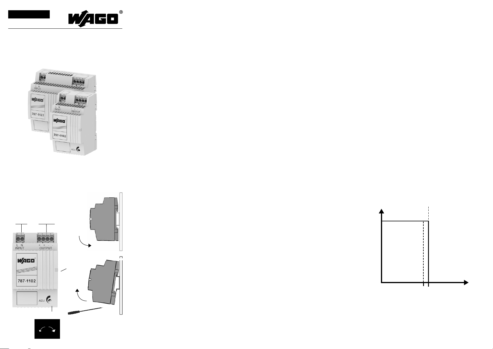
Anschluss
Connection
Ab b i ldun g zeigt de n 787-110 2
Thi s fi gur e sh ows the 78 7-1102
Eingang
3 4
input
+ –
Ausgang
output
+ + – –
5
6
1
Installation
Installation
Sicherheitsmaßnahmen vor der Installation
Das Betriebsmittel ist vor unzulässiger Beanspruchung zu
schützen. Insbesondere dürfen bei Transport und Handhabung keine Bauelemente verbogen und/oder Isolationsabstände verändert werden. Die Berührung elektrischer
Ba u eleme n t e und Kon t a k t e is t zu ver m e iden. Da s Be trieb s mittel immer im spannungsfreien Zustand montieren und
verdrahten. Die Produktbeschreibung und die technischen
Hinweise in unserem Hauptkatalog sowie die Aufschrif ten
am Be t r i e bsmi t tel un d au f dem Typens c h ild si n d zu beach t e n .
Installation
Di e Install a t ion is t en t sprech e nd den ör t l i c hen Ge g e benheiten, einschlägigen Vorschrif ten (z. B. VDE 0100),
nationalen Unfallverhütungsvorschrif ten (z. B. UVV-VBG4
bzw. BGV A3) und den anerkannten Regeln der Technik
durchzuführen. Dieses elektrische Betriebsmittel ist eine
Komponente, die zum Einbau in elektrische Anlagen oder
Maschinen bestimmt ist und erfüllt die Anforderungen der
Niederspannungsrichtlinie (2014/35/EU). Der geforderte
Mindestabstand zu benachbarten Teilen ist einzuhalten, um
die Kühlung nicht zu behindern! Bei Einbau in Maschinen ist
die Aufnahme des bestimmungsgemäßen Betriebes solange
untersagt, bis festgestellt wurde, dass die Maschine den
Bestimmungen der Maschinenrichtlinie (2006/42/EG)
entspricht. EN 60204 ist zu beachten. Die Aufnahme des
bestimmungsgemäßen Betriebes ist nur bei Einhaltung der
EMV-Richtlinie (2014/30/EU) erlaubt. Die Einhaltung der
durch die EMV-Gesetzgebung geforderten Grenzwerte
liegt in der Verantwortung des Herstellers der Anlage oder
Maschine.
LED: Di e grün e LE D le u c ht et , sofern
1
die Ausgangsspannung vorhanden ist.
Ausgangsspannung: Die Au s-
2
gangsspannung kann mit einem
Schraubendreher verändert werden.
Drehung im Uhrzeigersinn erhöht die
Ausgangsspannung. Drehung gegen
den Uhrzeigersinn verringert die
Ausgangsspannung.
Eingang
3
Ausgang
4
Montage: Setzen Sie das Gerät mit
5
de r Tra gsch i enenf ü h r ung an di e Ober ka n t e der Trag s c hien e an und ra s t e n
Si e es nach un t e n ein.
Demontage: Ziehen Sie den
6
Schnappriegel mit Hilfe eines
Schraubendrehers auf und hängen
Sie das Gerät an der Unterkante der
Tragschiene aus.
Safety measures before installation
This equipment is to be protected against improper use.
Components are not to be bent or isolation spacing changed,
especially through handling and transport. The contact with
electrical components and terminals is to be avoided. Always
disconnect the equipment from the mains supply, before
commencing installation or wiring. The product description,
technical information in our main catalogue and the marking
on th e eq uip m e nt ratin g s plat e ar e to be obser v e d .
Installation
Installation must be carried out according to the prevailing
local conditions and safety regulations (e.g. VDE 0100)
national accident prevention regulations (e.g. UVV-VBG4 or
BGV A3) and the generally accepted rules of technology. This
eq u ipme n t is a compo n e nt desi gned for in stall a t i on int o el e c trical systems and machines, and fulfils the requirements of
the low voltage guidelines (2014/35/EU).
The required minimum spacing to neighbouring components must be observed to guarantee the required cooling.
When installed into machinery, the normal operation is
forbidden until it is determined that the machine fulfils
the re q uirem e n t s of the ma c hin e r y guide l ines (2 0 06/42/
EG). EN 60204 must be observed. The EMC requirements
(2 014 / 30/EU ) must be ful f i lled be f o r e op erati o n is commenced. The observance of the required limitations for the
EMC legislation is the responsibility of the manufacturer of
the in stall a t i on or ma c hine r y.
LED: The green LED lights as soon as
1
the ou t put vol t a g e is pres e n t .
Output voltage: The output voltage
2
ca n be altered us i ng a scr e w d river.
Tur n ing the ad just m e n t screw cl o c kwi s e raise s th e output vo l t a ge. Tur ni n g the ad j ustmen t sc r ew anti c l o ckwi s e re duce th e ou t put vol t a g e .
Input
3
Output
4
Mounting: Place the device with the
5
DIN rail guide on the upper edge of the
DIN rail, and snap it in with a
downward motion.
Removing: Pull the snap lever open
6
with the aid of a screwdriver and slide
the device out at the lower edge of the
DIN rail.
Ausgangskennlinie (U/I Kennlinie)
Output characteristic (U/I Characteristic)
U
(V)
out
IN
1,1 x I
N
(A)
I
out
2
U
out
+–
Page 2
Technische Daten
Technical data
Eingangsdaten Input
Eingangsnennspannung
Rated input voltage
Eingangsspannungsbereich
Operating input voltage range
Eingangsspannungs-Derating
Derating input voltage
Nennfrequenzbereich
Rated frequency range
Eingangsnennstrom bei Nennlast
(11 0 / 230 Va c)
Rated input current at nominal load
110 / 230 Vac)
Einschaltstrombegr enzung
In-rush current limiter
Eingangssicherung intern int ern al fu se 2 AT 4 AT
Empfohlene Vorsicherung*
Recommended external protection*
Ne tza us fal lü ber br ück un g be i Nen nl ast (1 10 / 230 Vac )
Mains drop compensation at nominal load (110 / 230
Vac)
Ausgangsdaten Output
Ausgangsspannung
Rated output voltage
Ausgangsspannungsbereich
Rated output voltage range
Ausgangsstrom
Rated output current
Überlastverhalt en
Overloadbehaviour
Parallelschaltbar
Serienschaltbar
Verlustleistung (Leerlauf / Nennlast / Maximum)
Power loss (idle / nominal load / maximum)
Wirkungsgrad Efficiency ty p. 82 % ty p. 88 %
Restwelligkeit (Nennlast)
Residual ripple (nominal load)
Signalisierung Signaling
Betriebsanzeige
Power indicator
Um welt Environment
Lagertemperatur
Storage Temperature
Umgebungstemperatur
Ambient termperature
Derating -3 %/ K > +45 °C
Einbaulage Mounting position wa ag ere ch t für Tra gs chie ne TH 35, hor izo nt al fo r rai l TH 35
Zulässige Luftfeuchtigkeit
Allowable humidity
Strombelastbarkei t bei beliebiger Einbauanlage
Cu rr ent ra ti ng at a ny mo un t in g po sit ion
Kü hl ung ( A bs tan d zu be na ch bar ten Te il en)
Cooling (spacing to vicinal components)
Si cher hei t und S ch utz Safety and protection
Sc hut za rt Protection index IP 20
Prüfspannung
Schutzklasse Safety class II (im ge sc hlo ss ene n Sc hal ts chr an k) II (i n t he cl os ed ca bi ne t)
An sch lu ss kab el
Ei ns atz ber ei ch
Üb er spa nn ungs kat ego ri e
Rückspeisungsfestigkeit
Feedback voltage
No rmen Safety standards
Sicherheit Safety EN 615 58- 2-1 6, EN 609 50-1
EMV EMC EN 612 04- 3
Zulassungen Approvals
UL
GL Environmental category: C, EMC2
Bestellnummern Order numbers
Mechanik Mechanical Data
Gewicht wei gh t 0. 17 k g 0. 24 kg 0. 3 kg
Ma ße ( B x H x T)* *
Dimens ions widt h x height x depth**
An sch lü ss e Ein ga ng (L , N) / Aus ga ng (+, +, - , -) ***
Ter mina ls in pu t (L, N) / ou tp ut (+, +, - , -) ** *
* Für DC Eingangsspannung ist eine
geeignete DC-Sicherung erforderlich.
* For DC input voltage suitable DC fuse
required.
Parallel operation
Serial operation
HV te st vo lt age 4. 2 kVdc
Conductors Zu m A ns ch lus s Ku pfe rk abe l mi t min . 75 °C v er wen de n Use co pp er co nd uc tor s onl y, ra te d 75° C
Installation Ei ns atz in B er eic he n mit Ver sch mu tzu ng sgrad 2 Fo r ins ta lla ti on in p ol lut io n deg re e 2 env iro nm ent
Overvoltage category II
** Tiefe T ab Oberkante Tragschiene.
** Depth from upper edge of DIN rail.
787-1102 787-1112 787-1122
10 0 - 24 0 Vac
85 - 264 Vac (1 20 - 373 Vd c)
ma x. 1 A (< 10 0 Va c )
0. 7 / 0. 5 A 1. 4 / 0.6 A 1. 6 / 0 .9 A
6 A, 10 A , 16 A, C ha rak te ris t ik B, C 6 A, 10 A, 16 A, Ch ar act eri st ic B, C
1. 3 A 2. 5 A 4 A
2. 6 W / 7 W / 7.3 W 2. 2 W / 8 .5 W / 10 .5 W 0. 8 W / 1 3. 1 W / 14 .8 W
-2 5 °C – +6 0 °C (U L: -2 5 °C – +5 5 °C )
ma x. 0. 9 A ma x. 1. 6 A ma x. 2. 4 A
ke in Mi nd est ab sta nd re ch ts/ lin ks er f or der li ch , 50 mm obe n/unt en
UL- Not e: Ou tpu t d is c on nec t in g mea ns sh al l b e pr ovi ded duri n g in s tal lat i on .
787-11 02 787-1112 787-1 122
54 x 89 x 5 5 mm 72 x 89 x 55 mm 90 x 89 x 5 5 mm
ma x. 2 A (< 1 00 Vac ) /1. 8 A (<
90 Vac )
44 H z - 66 Hz / 0 Hz
< 30 A, N TC
10 / 80 ms 15 / 100 ms
24 Vd c ±2 %
22 .8 - 26 .4 Vdc
Ko ns tan tst rom ( U/ I Ken nl inie ) Con sta nt cu rr ent (U /I Li ne )
5 bi s 96 % re lat iv e Feu ch te, ke in e B et auu ng zul äss ig
5 to 96 % r el ati ve hu mi di ty wi th no de w
No min imu m sp ac ing rig ht/ lef t req uir ed , 50 mm o ve r/un de r
UL 508 (l is ted ), UL 6 09 50 -1 (r ec ogn iz ed)
WAG O pic oM AX® eC OM 5. 0 se rie s 20 92, ma x. 2, 5 mm²
*** picoMAX nur im spannungslosen Zustand ziehen oder stecken. Zum
Ziehen die Entriegelung mit Betätigungswerkzeug auslenken und picoMAX am
Steckergehäuse herausziehen, nicht an den Leitungen.
*** Pull or plug picoMAX in a powered down state. For pulling deflect the unlocking with operating tool. Pull picoMAX on the plug housing, not on the wire.
Ja Yes
Ja Yes
ty p. 10 0 mV
LE D grü n LE D gre en
-2 5 °C bi s +8 0 °C
Anlauf bei -40 ° C typgeprüft Device start at -40 ° C type-tested
ma x. 30 Vd c
ma x. 3. 5 A (< 100 Va c) / 3 A (< 90 Vac )
ss2
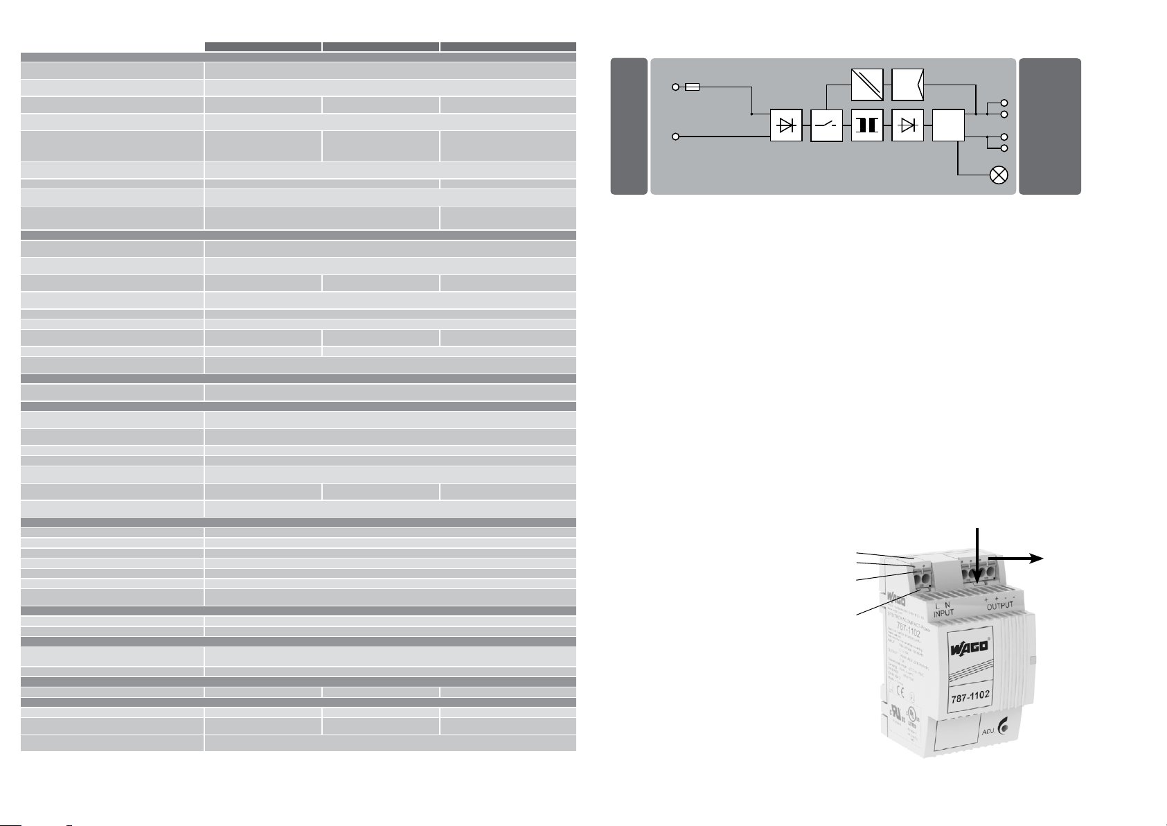
Funktionsschaltbild
Functional diagram
L (–)
N (+)*
* Zweiphasenbetrieb nur möglich, sofern die maximale Eingangsspannung von 264 Vac nicht überschritten wird.
* Two phase operation only possible, if input voltage under 264 Vac.
picoMAX-Federleisten bitte nur im spannungslosen Zustand
ziehen oder stecken.
Zu m Ziehe n bi t t e die Entri e g elun g slas c he (1) mit einem
Be t ä t i gung s w erkzeug ausle n ken und pi c oMAX am Fed e r leistengehäuse (2) herausziehen, nicht an den angeschlos-
senen Leitungen.
Beim Stecken darauf achten, dass die picoMAX-Federleiste
hö r b ar ein r astet. Ggf. durch Rü t t el n den Festsi t z ko n t r ollieren.
Starre Leiter oder Leiter mit Aderendhülse können direkt
gesteckt werden, bei flexiblen Leitern bitte den orangen
Betätigungsdrücker zum Öffnen der Klemmstelle nutzen.
Abisolierlänge 9..10 mm. Leiterquerschnitt ohne Aderendhü l se 0,2 mm ² ... 2,5 mm ², mi t Ader e n hüls e 0, 25 mm ² .. . 1,5
mm².
Das Lösen aller Leiterarten erfolgt über das Öffnen der
Kle m mstell e mi t t e ls des or a ngen Be t ä t i gung s drüc k e r s (3).
Ei n e Prüföf f nung (4) an jeder Klemmstelle erlaubt die
Please pull or plug picoMAX-female connectors only in a
powered down state.
Fo r pulli n g deflect the un lock i n g (1) with an operating tool.
Pu l l picoM A X on th e ho usi n g (2), not on th e co nnected wi r e s .
When inser ting, make sure that the picoMAX female
connector clicks audible. If necessary, test the tightness by
vibration.
Rigid conductors or conductors with ferrules can be
inserted directly. For stranded conductors please use the
orange actuating pusher for opening the terminal point .
Stripping length 9..10 mm. Conductor cross-section without
wire end-ferrules 0.2 mm² ... 2.5 mm², with wire-end ferrules
0. 2 5 mm² .. . 1. 5 mm².
At all types of conductors the release is done with opening of
the te r m ina l po int via th e orang e ac t uatin g pushb u t t o n (3).
A tes t ho le (4) on each terminal point allows voltage test
wi t h o u t open i ng the term i nal po i n t by 1mm pr o be.
Spannungsprüfung ohne Öffnen der Klemmstelle mittels
Pr ü f s p it ze 1 mm.
2
4
3
1
WAGO Kontakttechnik GmbH & Co. KG
Hansastr. 27
32423 Minden
Germany
Phone: +49 571-887-0
Fax: +49 571-887-169
info@wago.com
www.wago.com
Technische Änderungen vorbehalten.
Subject to change.
Stand-by
1.
–
–
+
+
LED (Green)
2.
 Loading...