

Manual
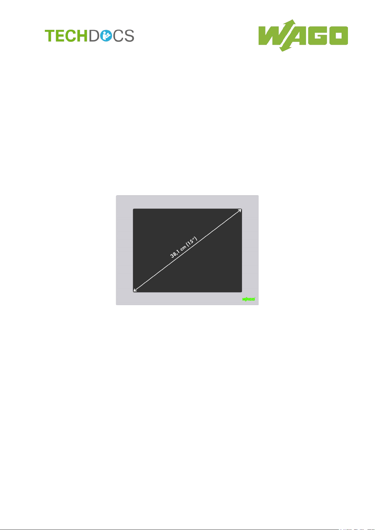
WAGO PERSPECTO® 762
762-3150/000-003
CP 150 XGA TV CAN
PERSPECTO
Target Visualization
Version 1.0.2
®
CP, Control Panel with CoDeSys

2 WAGO PERSPECTO® 762
762-3150/000-003 CP 150 XGA TV CAN
© 2018 WAGO Kontakttechnik GmbH & Co. KG
All rights reserved.
Manual
Version 1.0.2

WAGO PERSPECTO® 762 Table of Contents 3
762-3150/000-003 CP 150 XGA TV CAN
Table of Contents
1 Notes about this Documentation ............................................................. 5
1.1 Scope of Validity ..................................................................................... 5
1.2 Copyright ................................................................................................ 5
1.3 Symbols ................................................................................................. 6
1.4 Number Notation .................................................................................... 8
1.5 Font Conventions ................................................................................... 8
2 Important Notes ........................................................................................ 9
2.1 Legal Bases ............................................................................................ 9
2.1.1 Subject to Changes ............................................................................ 9
2.1.2 Personnel Qualification ...................................................................... 9
2.1.3 Use of the 762 Series in Compliance with Underlying Provisions ....... 9
2.1.4 Technical Condition of Specified Devices........................................... 9
2.2 Safety Advice (Precautions) ................................................................. 11
3 Device Description .................................................................................. 13
3.1 Control Panel with Target Visualization PERSPECTO CP TV .............. 13
3.2 View ..................................................................................................... 14
3.2.1 Front View ........................................................................................ 14
3.2.2 Back View ........................................................................................ 15
3.3 Connectors ........................................................................................... 16
3.3.1 X1 – Supply Voltage ........................................................................ 16
3.3.2 X2 – Serial Interface RS-232/RS-485/RS-422 (COM 2) ................... 17
3.3.3 X3 – Serial Interface RS-232 (COM 1) ............................................. 18
3.3.4 X5 – CAN 0 Interface ....................................................................... 19
3.3.5 X6 – ETHERNET Interface 10/100/1000 MBit .................................. 20
3.3.6 X8/X9/X10/X11 – USB Interfaces ..................................................... 21
3.4 Battery Case ......................................................................................... 22
3.5 Slot for Memory Card ........................................................................... 23
6 Operating Elements .............................................................................. 24
3.
3.6.1 Service Button.................................................................................. 24
3.7 Technical Data ..................................................................................... 25
3.7.1 Housing............................................................................................ 25
3.7.2 Power Supply ................................................................................... 25
3.7.3 Display ............................................................................................. 25
3.7.4 Hardware ......................................................................................... 26
3.7.5 Software........................................................................................... 26
3.7.6 Interfaces ......................................................................................... 26
3.8 Approvals ............................................................................................. 27
3.9 Standards and Guidelines .................................................................... 27
4 Mounting .................................................................................................. 28
4.1 Front Panel Installation ......................................................................... 28
5 Connect Devices ..................................................................................... 29
5.1 Supply voltage ...................................................................................... 29
5.2 Grounding............................................................................................. 29
5.3 Peripheral Devices ............................................................................... 29
Manual
Version 1.0.2

4 Table of Contents WAGO PERSPECTO® 762
762-3150/000-003 CP 150 XGA TV CAN
6 Commissioning ....................................................................................... 30
6.1 Switch on .............................................................................................. 30
6.2 IP Address of the Device ...................................................................... 31
6.2.1 General ............................................................................................ 31
6.2.2 Setting the IP Address ..................................................................... 31
6.2.3 IP Address ....................................................................................... 32
6.3 The WAGO Control Center ................................................................... 33
6.3.1 Starting the WAGO Control Center .................................................. 33
6.3.2 “General” Tab .................................................................................. 34
6.3.3 “Autostart Applications” Tab ............................................................. 35
6.3.4 “Users” Tab ...................................................................................... 36
6.3.5 “FTP” Tab ........................................................................................ 37
6.3.6 “HTTP” Tab ...................................................................................... 38
6.3.7 “RAS” Tab ........................................................................................ 39
6.3.8 “Backup/Restore” Tab ...................................................................... 40
6.3.9 “Advanced” Tab ............................................................................... 42
6.3.10 Saving the Configuration .................................................................. 43
6.4 Target-Visu ........................................................................................... 44
7 Service ..................................................................................................... 45
7.1 Battery Maintenance ............................................................................. 45
List of Figures .................................................................................................. 46
List of Tables .................................................................................................... 47
Manual
Version 1.0.2

WAGO PERSPECTO® 762 Notes about this Documentation 5
762-3150/000-003 CP 150 XGA TV CAN
1 Notes about this Documentation
The CP 150 XGA TV CAN 762-3150/000-003 shall only be installed and
operated according to the instructions in these operating.
Always retain this documentation!
This documentation is part of the product. Therefore, retain the documentation
during the entire service life of the product. Pass on the documentation to any
subsequent user. In addition, ensure that any supplement to this documentation
is included, if necessary.
1.1 Scope of Validity
This documentation applies to PERSPECTO-Panel 762-3150/000-003 (CP 150
XGA TV CAN).
1.2 Copyright
This Manual, including all figures and illustrations, is copyright-protected. Any
further use of this Manual by third parties that violate pertinent copyright
provisions is prohibited. Reproduction, translation, electronic and phototechnical
filing/archiving (e.g., photocopying) as well as any amendments require the
written consent of WAGO Kontakttechnik GmbH & Co. KG, Minden, Germany.
Non-observance will involve the right to assert damage claims.
Manual
Version 1.0.2
6 Notes about this Documentation WAGO PERSPECTO® 762
762-3150/000-003 CP 150 XGA TV CAN
1.3 Symbols
Personal Injury!
Indicates a high-risk, imminently hazardous situation which, if not avoided, will
result in death or serious injury.
Personal Injury Caused by Electric Current!
Indicates a high-risk, imminently hazardous situation which, if not avoided, will
result in death or serious injury.
Personal Injury!
Indicates a moderate-risk, potentially hazardous situation which, if not avoided,
could result in death or serious injury.
Personal Injury!
Indicates a low-risk, potentially hazardous situation which, if not avoided, may
result in minor or moderate injury.
Damage to Property!
Indicates a potentially hazardous situation which, if not avoided, may result in
damage to property.
Damage to Property Caused by Electrostatic Discharge (ESD)!
Indicates a potentially hazardous situation which, if not avoided, may result in
damage to property.
Important Note!
Indicates a potential malfunction which, if not avoided, however, will not result in
damage to property.
Manual
Version 1.0.2

WAGO PERSPECTO® 762 Notes about this Documentation 7
762-3150/000-003 CP 150 XGA TV CAN
Additional Information:
Refers to additional information which is not an integral part of this
documentation (e.g., the Internet).
Manual
Version 1.0.2
8 Notes about this Documentation WAGO PERSPECTO® 762
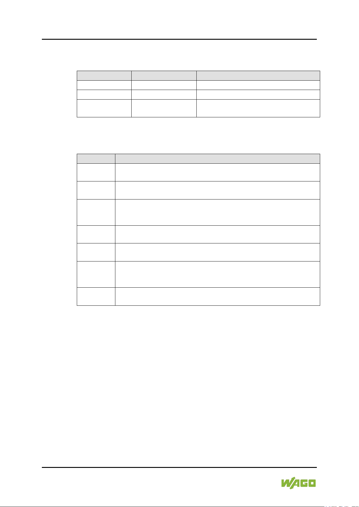
Table 1: Number Notation
Number Code
Example
Note
Decimal
100
Normal notation
Hexadecimal
0x64
C notation
Binary
'100'
'0110.0100'
In quotation marks, nibble separated
with dots (.)
Table 2: Font Conventions
Font Type
Indicates
italic
Names of paths and data files are marked in italic-type.
Menu
Menu items are marked in bold letters.
e.g.: Save
>
A greater-than sign between two names means the selection of a
e.g.: File > New
Input
Designation of input or optional fields are marked in bold letters,
Start of measurement range
“Value”
Input or selective values are marked in inverted commas.
Start of measurement range
[Button]
Pushbuttons in dialog boxes are marked with bold letters in square
e.g.: [Input]
[Key]
Keys are marked with bold letters in square brackets.
e.g.: [F5]
762-3150/000-003 CP 150 XGA TV CAN
1.4 Number Notation
1.5 Font Conventions
e.g.: C:\Program Files\WAGO Software
menu item from a menu.
e.g.:
e.g.: Enter the value “4 mA” under
brackets.
.
Manual
Version 1.0.2
WAGO PERSPECTO® 762 Important Notes 9
762-3150/000-003 CP 150 XGA TV CAN
2 Important Notes
This section includes an overall summary of the most important safety
requirements and notes that are mentioned in each individual section. To protect
your health and prevent damage to devices as well, it is imperative to read and
carefully follow the safety guidelines.
2.1 Legal Bases
2.1.1 Subject to Changes
WAGO Kontakttechnik GmbH & Co. KG reserves the right to provide for any
alterations or modifications. WAGO Kontakttechnik GmbH & Co. KG owns all
rights arising from the granting of patents or from the legal protection of utility
patents. Third-party products are always mentioned without any reference to
patent rights. Thus, the existence of such rights cannot be excluded.
2.1.2 Personnel Qualification
All sequences implemented on Series 762 devices may only be carried out by
electrical specialists with sufficient knowledge in automation technology. These
specialists must be familiar with the current standards and guidelines for the
devices and the automated environments.
All changes to the controller shall always be performed by qualified personnel
with sufficient skills in PLC programming.
2.1.3 Use of the 762 Series in Compliance with Underlying
Provisions
762 Series modules are suitable for use in the area of time control and
automation. Their use extends beyond residential and commercial areas, as well
as industrial areas. Technical data must be observed for all types of applications.
Radio interference in residential areas
This is a class A device. This device can cause radio interference in residential
areas. In this case, the operator may be required to take appropriate measures.
2.1.4 Technical Condition of Specified Devices
The devices to be supplied ex works are equipped with hardware and software
configurations, which meet the individual application requirements. These
modules contain no parts that can be serviced or repaired by the user. The
Manual
Version 1.0.2
10 Important Notes WAGO PERSPECTO® 762
762-3150/000-003 CP 150 XGA TV CAN
following actions will result in the exclusion of liability on the part of WAGO
Kontakttechnik GmbH & Co. KG:
• Repairs,
• Changes to the hardware or software that are not described in the
operating instructions,
• Improper use of the components.
Further details are given in the contractual agreements. Please send your
request for modified and new hardware or software configurations directly to
WAGO Kontakttechnik GmbH & Co. KG.
Pixel error in TFT display
Any pixel errors of the TFT display due to production reasons do not represent
grounds for complaint!
Manual
Version 1.0.2
WAGO PERSPECTO® 762 Important Notes 11
762-3150/000-003 CP 150 XGA TV CAN
2.2 Safety Advice (Precautions)
For installing and operating purposes of the relevant device to your system the
following safety precautions shall be observed:
Do not work on devices while energized!
All power sources to the device shall be switched off prior to performing any
installation, repair or maintenance work.
Install only in appropriate housings, cabinets or in electrical operation
rooms!
The device is an open unit. As such, install it exclusively in appropriate housings,
cabinets or in electrical operation rooms. Allow access to authorized staff only by
means of specific keys or tools.
Replace defective or damaged devices!
Replace defective or damaged device/module (e.g., in the event of deformed
contacts), since the long-term functionality of device/module involved can no
longer be ensured.
Protect the components against materials having seeping and insulating
properties!
The components are not resistant to materials having seeping and insulating
properties such as: aerosols, silicones and triglycerides (found in some hand
creams). If you cannot exclude that such materials will appear in the component
environment, then install the components in an enclosure being resistant to the
above-mentioned materials. Clean tools and materials are imperative for
handling devices/modules.
Clean only with permitted materials!
Clean housing and soiled contacts with propanol.
Manual
Version 1.0.2
12 Important Notes WAGO PERSPECTO® 762
762-3150/000-003 CP 150 XGA TV CAN
Do not use any contact spray!
Do not use any contact spray. The spray may impair contact area functionality in
connection with contamination.
Do not use in telecommunication circuits!
Only use devices equipped with ETHERNET or RJ-45 connectors in LANs.
Never connect these devices with telecommunication networks.
Avoid electrostatic discharge!
The devices are equipped with electronic components that may be destroyed by
electrostatic discharge when touched. Please observe the safety precautions
against electrostatic discharge per DIN EN 61340-5-1/-3. When handling the
devices, please ensure that environmental factors (personnel, work space and
packaging) are properly grounded.
Manual
Version 1.0.2

WAGO PERSPECTO® 762 Device Description 13
762-3150/000-003 CP 150 XGA TV CAN
3 Device Description
The 762 Series panels are used to operate and visualize the controllers of the
WAGO-I/O-SYSTEM. The integrated WAGO-AUTOMATION COCKPIT
development environment is used to program the panels and controllers.
3.1 Control Panel with Target Visualization
PERSPECTO CP TV
In addition to target visualization, the control panel with target visualization also
has a CODESYS runtime, making it a full-fledged automation device.
PERSPECTO CP provides configurable functions for operation and monitoring,
and can independently process control tasks.
The PLC functionality is based on the IEC 61131-compatible CODESYS
environment. Corresponding libraries provide hardware access - even from a
PLC program.
Manual
Version 1.0.2
14 Device Description WAGO PERSPECTO® 762
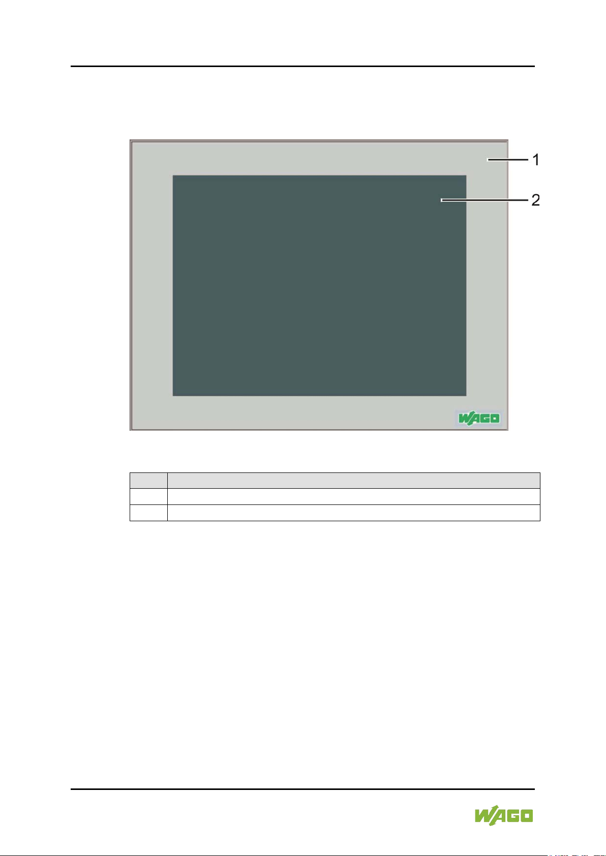
Table 3: Legend for Figure “Front View”
No.
Description
1
Front panel
2
Touch screen display
762-3150/000-003 CP 150 XGA TV CAN
3.2 View
3.2.1 Front View
Figure 1: Front View
Manual
Version 1.0.2
WAGO PERSPECTO® 762 Device Description 15
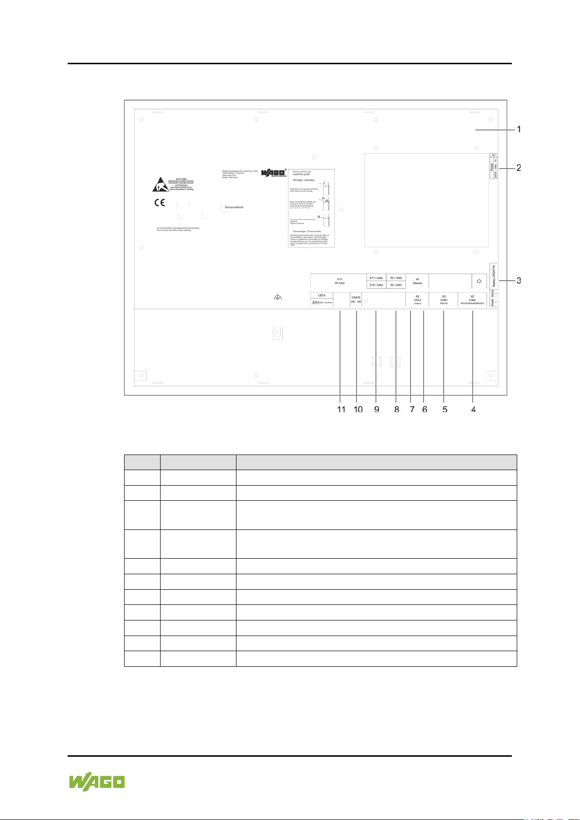
Table 4: Legend for Figure “Back View”
No.
Designation
Description
1
-
Housing 2 X1
Connection for 24VDC power supply
3V Battery
RS-232 or RS-485/RS-422 serial interface (COM 2) as Dsub 9 connector
5
X3
RS-232 serial interface (COM 1) as D-sub 9 connector
6
X6
ETHERNET interface as RJ45 jack
7
X5
CAN-Bus 0 (CANopen) interface as RJ45 jack
8
X8/X9
USB host interfaces
9
X10/X11
USB host interfaces
10
CAN-R
Switch for CAN bus termination
11
X13
Slot for SD memory card
762-3150/000-003 CP 150 XGA TV CAN
3.2.2 Back View
Figure 2: Back View
3
4 X2
CR2477N
Battery case
Manual
Version 1.0.2

16 Device Description WAGO PERSPECTO® 762
Table 5: X1 Pin Assignment
Pin
Assignment
Function
1
+24 V
Supply Voltage
2
0 V GND
Reference potential GND
3
FE
Ground conductor
762-3150/000-003 CP 150 XGA TV CAN
3.3 Connectors
3.3.1 X1 – Supply Voltage
Use the X1 connection for the device power supply. More information about the
power supply and power consumption is available in the "Technical Data"
section.
Figure 3: Connector X1 – Supply Voltage
Manual
Version 1.0.2

WAGO PERSPECTO® 762 Device Description 17
Table 6: X2 Pin Assignment
Pin
Assignment
Function
1
Y (Tx+)
RS-485
2
RxD
Receive Data for RS-232
3
TxD
Transmit Data for RS-232
4
Z (Tx-)
RS-485
5
GND 5V
Signal Ground
6
R-
Terminating resistor -
7
B (Rx-)
RS-485
8
A (Rx+)
RS-485
9
R+
Terminating resistor +
762-3150/000-003 CP 150 XGA TV CAN
3.3.2 X2 – Serial Interface RS-232/RS-485/RS-422 (COM 2)
The interface is designed as a combined RS-232/RS-485/RS-422 interface. It is
DC coupled with the power supply of the device. It is generally used for
communication (service devices, modem operation, etc.).
The connected data cable must be shielded.
Figure 4: Connector X2 – Serial Interface RS-232/RS-485/RS-422
Manual
Version 1.0.2

18 Device Description WAGO PERSPECTO® 762
Table 7: X3 Pin Assignment
Pin
Assignment
Function
1
DCD
Data carrier detect
2
RxD
Receive Data for RS-232
3
TxD
Transmit Data for RS-232
4
DTR
Data Terminal ready
5
GND 5V
Signal Ground
6
DSR
Data set ready
7
RTS
Request to send
8
CTS
Clear to send
9
RI
Ring indicator
762-3150/000-003 CP 150 XGA TV CAN
3.3.3 X3 – Serial Interface RS-232 (COM 1)
The interface is designed as an RS-232 interface. It is DC coupled with the
device ground. The interface is used for modem operation or for user-specific
protocols.
The connected data cable must be shielded.
A null modem connection is used to connect to another device with RS-232
interface. A 1:1 connecting cable is used to connect to a modem.
Figure 5: Connector X3 – Serial Interface RS-232
Manual
Version 1.0.2

WAGO PERSPECTO® 762 Device Description 19
Table 8: X5 Pin Assignment
Pin
Assignment
Function
1
CAN_L
CAN data low dominant
2
CAN H
CAN data high dominant
3
GND
Ground
4
-
Not used
5
Do not use!
Not used
6
Do not use!
Not used
7
-
Not used
8
-
Not used
762-3150/000-003 CP 150 XGA TV CAN
3.3.4 X5 – CAN 0 Interface
This interface is designed as an RJ45 connector. The interface is used to
communicate with CANopen-enabled modules.
The CAN 0 interface is designed with electrical isolation in accordance with ISO
11898. A terminating resistor that can be switched on by relay is integrated in the
device in accordance with ISO11898.
The connected data cable must be shielded.
Figure 6: Connector X5 – CAN 0 Interface RJ-45
Manual
Version 1.0.2

20 Device Description WAGO PERSPECTO® 762
Table 9: X6 Pin Assignment
10/100 MBit
1000 MBit
Assignment
Function
Assignment
Function
1
TX+
Transmit Data +
MDI0+
2
TX-
Transmit Data -
MDI0-
3 RX+
Receive Data +
MDI1+
4
n.c.
-
MDI2+
5
n.c.
-
MDI2-
6
RX-
Receive Data -
MDI1-
7
n.c.
-
MDI3+
8
n.c.
-
MDI3-
762-3150/000-003 CP 150 XGA TV CAN
3.3.5 X6 – ETHERNET Interface 10/100/1000 MBit
An RJ45 jack is used for the ETHERNET interface.
The connections and cables must meet CAT.5 and the guidelines for ETHERNET
interfaces 10/100/1000 MBit.
If there are more than 2 devices in a network, then they must be connected to
each other by a HUB or SWITCH.
The type of connection is detected automatically via auto-MDI(x).
Figure 7: Connector X6 ‒ ETHERNET RJ45
Pin
Manual
Version 1.0.2

WAGO PERSPECTO® 762 Device Description 21
Table 10: X8/X9/X10/X11 Pin Assignment
Pin
Assignment
Function
1
USB_VCC1
USB +5V DC
2
USB_N1
USB data line N1
3
USB_P1
USB data line P1
4
USB_GND
USB GND
762-3150/000-003 CP 150 XGA TV CAN
3.3.6 X8/X9/X10/X11 – USB Interfaces
The interfaces are designed as USB host interfaces, type A.
The following table and illustration provide information on the pin assignment of
the interfaces. The interface connection meets the USB specification 2.0.
Figure 8: Connectors X8/X9/X10/X11 – USB Interfaces
Manual
Version 1.0.2

22 Device Description WAGO PERSPECTO® 762
762-3150/000-003 CP 150 XGA TV CAN
3.4 Battery Case
Do not charge, disassemble or burn the battery!
Incorrect use of the lithium battery contained in this device may cause damage
incurred by fire or chemical burns. The battery must not be charged,
disassembled, burned or exposed to temperatures exceeding 100°C (212°F).
The battery compartment holds a 3 V lithium battery, type CR2477N or Z3605,
that supplies the real time clock with power in case of a power failure.
If you want to change the lithium battery during a power failure, make sure that
you have the new battery ready to hand. For a certain time a gold cap capacitor
provides the required power.
At room temperature, the battery has a life span of about one year.
Figure 9: Battery Case
It is possible to check the capacity of the battery via the CODESYS function
SysRtcCheckBattery.
Manual
Version 1.0.2

WAGO PERSPECTO® 762 Device Description 23
762-3150/000-003 CP 150 XGA TV CAN
3.5 Slot for Memory Card
The panel 762-3150/000-003 is equipped with a Flash memory slot on the side
for a CF card. It supports cards with a 2 GB maximum. Supported memory cards
(item no. 758-879/000-000) are available from WAGO.
Manual
Version 1.0.2

24 Device Description WAGO PERSPECTO® 762
762-3150/000-003 CP 150 XGA TV CAN
3.6 Operating Elements
3.6.1 Service Button
The service switch on the back of the device is used to call up the Windows CD
desktop. The WAGO Control Center can be launched, for example, to configure
the device.
Figure 10: Service Button
Manual
Version 1.0.2

WAGO PERSPECTO® 762 Device Description 25
Table 11: Technical Data ‒ Housing
Front panel
Anodized aluminum, natural,
polyester film
Housing material
Painted sheet steel
Dimensions (W x H x L)
398 x 306 x 77 mm
Panel cutout (B x H)
383 x 291 mm
Fixing means
6 clamping elements
Surrounding air temperature, operation
0 °C ... +45 °C
Surrounding air temperature, storage
-10 °C ... +60 °C
Relative humidity (without
condensation)
10 % ... 85 %
Weight
4500 g
Degree of protection
Front IP65,
back IP20
Table 12: Technical Data ‒ Power Supply
Voltage supply
DC 24 V (18 ... 30 V)
Max. input current (24 V)
1300 mA
Operating power
28 ... 35 W
Buffer battery
CR2477N
Table 13: Technical Data ‒ Display
Display type
TFT
Screen size (diagonal)
38.1 cm (15“)
Display colors
16 million
Graphics resolution
1024 x 768 pixel
Contrast ratio
500:1
Angle of view horizontal / vertical
-75 ° ... +75 ° / -60 °... +60 °
Brightness
250 cd/m²
HBT*
50,000 hrs.
Panel
Touch, analog, resistive
Light transmission
typ.
80%
Durability
35 Mio. activations with finger
762-3150/000-003 CP 150 XGA TV CAN
3.7 Technical Data
3.7.1 Housing
3.7.2 Power Supply
3.7.3 Display
* HBT (Half Brightness Time) defines the LED chip brightness decrease to
50% original brightness at Ta = 25 ± 2°C and RH = 60 ± 10%.
Manual
Version 1.0.2

26 Device Description WAGO PERSPECTO® 762
Table 14: Technical Data ‒ Hardware
Processor
Intel Atom® N270 1.6 GHz
RAM / Flash / SRAM
256 MB / 128 MB / -
Memory expansion
CF card (max. 2 GB)
Table 15: Technical Data ‒ Software
Operating system
Windows CE 6.0
Software configuration
PLC runtime with target visualization
panel configuration software
Table 16: Technical Data ‒ Interfaces
USB interfaces
4 x USB2.0 host (type A)
ETHERNET interface
1 x 10/100 Mbit RJ45
CAN interface
1 x RJ45
Serial interfaces
1 x RS-232 D-sub 9,
1 x RS-232 + RS-485/RS-422 D-sub 9
Maximum length of connecting cables
USB: maximum 3 m
supply
762-3150/000-003 CP 150 XGA TV CAN
3.7.4 Hardware
3.7.5 Software
(CODESYS),
3.7.6 Interfaces
Serial RS-232: maximum 10 m
Serial RS-485/RS-422: maximum 30 m
ETHERNET: maximum 100 m
Power supply: maximum 3 m to power
Manual
Version 1.0.2

WAGO PERSPECTO® 762 Device Description 27
Conformity Marking
762-3150/000-003 CP 150 XGA TV CAN
3.8 Approvals
The following approvals have been granted to 762-3150/000-003 panels:
3.9 Standards and Guidelines
762-3150/000-003 panels meet the following requirements on emission and
immunity of interference:
EMC CE-Immunity to interference EN 61000-6-2
EMC CE-Emission of interference EN 61000-6-4
Manual
Version 1.0.2

28 Mounting WAGO PERSPECTO® 762
762-3150/000-003 CP 150 XGA TV CAN
4 Mounting
4.1 Front Panel Installation
The devices are intended for installation in switch cabinets, for example.
Vertical installation of the panels is recommended.
Note about differing mounting position!
The operating temperature ranges specified in the technical data apply to the
recommended mounting position. If the panel is mounted in a position different
than recommended, cooling can be affected. Contact WAGO Service for more
information.
The PERSPECTO Series panels are used in the panel cutout provided and bolted
down with the included clamping elements from behind (note the following
installation diagram).
Figure 11: Installation of the Clamping Elements
Information on the dimensions of the panel cutout is available in the Technical
Data section.
Manual
Version 1.0.2

WAGO PERSPECTO® 762 Connect Devices 29
762-3150/000-003 CP 150 XGA TV CAN
5 Connect Devices
5.1 Supply voltage
Connect the supply voltage to contact 1 (24 VDC) and contact 2 (GND) of the
included 734-103 female connector. Use an appropriate operating tool to open
the CAGE CLAMP
cross section of max. 1.5 mm² into the connections and remove the operating
tool.
5.2 Grounding
Connect the functional earth to the grounding screws or lugs on the housing and
to contact 3 (FE) of the included female connector as described in the previous
section. Plug the female connector onto the X1 male connector (power) and then
verify that the clamping connection is secured.
®
connections. Feed the 7 mm stripped conductors with a
5.3 Peripheral Devices
The interfaces to the back of the device are used to connect the peripheral
devices electrically. The number and arrangement of the interfaces depend on
the design (note the information in the "Technical Data" chapter or “Connection”
chapter).
The RS-232 interface is used to program and diagnose the devices. Various
software tools can be used for modem operation, remote maintenance, etc.
The RS-485(/RS-422) interface is used as a communication interface to other
devices.
The CAN interface with electrical isolation is used as a communication interface
to other CAN devices.
The CAN-0 interface has a connectable termination resistor. Protocols are
defined while programming the device.
The Ethernet interface is used for connection to a LAN.
The USB master interfaces are used for connecting to a keyboard, mouse or
USB stick. Because there are a large number of USB devices on the market, no
guarantee can be made about the function of individual devices.
Manual
Version 1.0.2

30 Commissioning WAGO PERSPECTO® 762
762-3150/000-003 CP 150 XGA TV CAN
6 Commissioning
6.1 Switch on
After applying the power supply, the device switches on automatically.
After the boot and self-test phase that lasts about 10 seconds, the programs set
in the WAGO Control Center (e.g. HMI runtime) are launched automatically.
To stop the programs and Windows CE desktop for configuring the panels from
launching automatically, the touch screen must be touched within a adjustable
time period (default setting 3 s) after the boot & self-test phase.
The service switch on the back of the device can be used to launch the Windows
CE desktop at any time.
The WAGO Control Center can be used to change the start behavior of the
device.
Time window for launching the Windows CE desktop!
The WAGO Control Center can be used to set the time window for launching the
Windows CE desktop after the boot and self-test phase.
If the time is set to 0, the Windows CE desktop can only be launched by the
service switch.
Manual
Version 1.0.2

WAGO PERSPECTO® 762 Commissioning 31
762-3150/000-003 CP 150 XGA TV CAN
6.2 IP Address of the Device
6.2.1 General
The device can be programmed using WAGO-I/O-PRO / CODESYS.
Therefore, a TCP/IP connection is required. An IP address must be assigned to
the device after switching it on for the first time.
The WAGO Control Center installed on the device is used to assign the IP
address by default (observe "Setting the IP Address" section).
The device can either draw its IP address from a DHCP server on the network or
the device can be assigned a fixed IP address.
The current IP address can be queried by double-clicking on the network icon in
the system tray in the task bar.
DHCP / fixed IP address
The device must be connected to a network to change the IP address from
DHCP to a fixed IP address.
6.2.2 Setting the IP Address
The WAGO Control Center is used to set the IP address. Call up the WAGO
Control Center from the Start menu:
Start > Programs > Utilities > WAGO Control Center
1. Click the Advanced tab and then on the [LAN] button.
2. In the "Adapter Settings", click on the IP Address tab.
3. Enter the desired IP address and click [OK] to confirm.
Manual
Version 1.0.2

32 Commissioning WAGO PERSPECTO® 762
762-3150/000-003 CP 150 XGA TV CAN
Figure 12: IP Address
6.2.3 IP Address
When using a crossover cable to connect between the panel and configuring PC
directly, it is recommended that both devices have fixed IP addresses with an open
address in the range 192.168.1.xxx.
In this case, the subnet mask is automatically set to 255.255.255.0. There is no
default gateway.
IP Address
The devices must be set to different IP addresses.
Manual
Version 1.0.2

WAGO PERSPECTO® 762 Commissioning 33
762-3150/000-003 CP 150 XGA TV CAN
6.3 The WAGO Control Center
The WAGO Control Center can be used to configure the device. Settings for the
Autostart programs, uses, FTP/HTTP and RAS access can be made. General
device settings can also be checked and modified.
6.3.1 Starting the WAGO Control Center
The WAGO Control Center is launched from the Start menu:
Start > Programs > Utilities > WAGO Control Center
The tabs of the WAGO Control Center are explained on the following pages.
Manual
Version 1.0.2

34 Commissioning WAGO PERSPECTO® 762
762-3150/000-003 CP 150 XGA TV CAN
6.3.2 “General” Tab
Figure 13: “General” Tab
Device Information
Information about the device is found here. This information is important, for
example, for support cases.
General
Watchdog:
A watchdog can be configured here, which can restart the device if it
crashes after a set time.
Don’t start Windows CE Shell:
If the checkbox is enabled, the Windows CE desktop can no longer be
launched. The task bar is no longer displayed.
Simple Network Time protocol:
If there is an Internet connection, the system clock of the device can be
synchronized via an SNTP server.
Client Only
If the checkbox is enabled, the internal SNTP server is disabled.
Manual
Version 1.0.2

WAGO PERSPECTO® 762 Commissioning 35
762-3150/000-003 CP 150 XGA TV CAN
6.3.3 “Autostart Applications” Tab
You can enter programs here that should launch automatically after booting. The
target-visu runtime, the autoscan function and the WAGO Control Center are
entered here by default.
The time window for launching the programs after the boot and self-test phase of
the device can also be set here.
Figure 14: “Autostart Applications” Tab
Manual
Version 1.0.2

36 Commissioning WAGO PERSPECTO® 762
762-3150/000-003 CP 150 XGA TV CAN
6.3.4 “Users” Tab
You can create FTP users, grant rights and assign directories. The menu is
generally self-explanatory.
Figure 15: “Users” Tab
User/Virtual Roots:
A directory from another (protected) tree, for example, can be put in the user's
home directory. By doing so, you gain access to this and subsequent directories.
FTP Home Directory/HTTP directory path:
The user starts downwards from this menu. The use cannot get to higher-level
directories.
Rights:
Access rights assigned to users are displayed here.
Access Rights
If no home directory is set for a user, the user gets FULL ACCESS to the panel
despite disabled write access. Enter at least on \ in the home directory.
Manual
Version 1.0.2

WAGO PERSPECTO® 762 Commissioning 37
762-3150/000-003 CP 150 XGA TV CAN
6.3.5 “FTP” Tab
You can configure the FTP server of the device here.
More information about creating users is available in the "Users Tab" section.
Figure 16: “FTP” Tab
Manual
Version 1.0.2

38 Commissioning WAGO PERSPECTO® 762
762-3150/000-003 CP 150 XGA TV CAN
6.3.6 “HTTP” Tab
You can configure the Web server of the device here.
Figure 17: “HTTP” Tab
Application example:
An \httptest directory with the /test alias was created on the flash disk.
A Web page index.htm was created in this directory.
The page can be used in a Web browser to access the following address:
http://[IP address of the device]/test
Manual
Version 1.0.2

WAGO PERSPECTO® 762 Commissioning 39
762-3150/000-003 CP 150 XGA TV CAN
6.3.7 “RAS” Tab
The Remote Access Service (RAS) is a service for remote access to a Windows
CE device.
Figure 18: “RAS” Tab
Both RAS functions, server and client, are supported.
The connection between a RAS client and the RAS server can be established via
a modem, VPM or direct connection.
For more information about the Remote Access Service (RAS) of the device,
please contact WAGO Support.
Manual
Version 1.0.2

40 Commissioning WAGO PERSPECTO® 762
762-3150/000-003 CP 150 XGA TV CAN
6.3.8 “Backup/Restore” Tab
You can save and restore the device configuration and project data, for example,
on a memory card.
Doing so allows you to restore the data to the new device when replacing a
defective device without having to redo all the settings.
What data and files should be saved is defined by the backup_restore.cfg file.
The file is stored on the device via the path \Flashdisk\SysExtras\Tools\
backup_restore.cfg
The file is divided into three sections.
[REGISTRY]
"\Memory Stick\wago\backup\registry.reg"
[HKEY_LOCAL_MACHINE\Drivers\BuiltIn\BackLight];MaxIntensity
The section devices the registry entries to be saved. The path indicates where
the registry entries shall be saved.
The registry entries to be saved are listed there.
[SRAM]
;Destination path; filename or automatically sram.bin
"\Memory Stick\wago\backup\sram"
The path indicates where the SRAM content shall be saved.
[FILES]
default.*;"\FlashDisk\PLCWinCE\";"\Memory Stick\wago\backup\FlashDisk\
ElaDesign\"
The section devices the files on the device to be saved.
• default.*; specified the file that should be saved. Wildcards such as *.*
and.* are permitted.
• "\FlashDisk\PLCWinCE\"; defines the path of the file to be saved.
• "\Memory Stick\wago\backup\FlashDisk\PLCWinCE\" defines the path
where the file should be saved.
Manual
Version 1.0.2

WAGO PERSPECTO® 762 Commissioning 41
762-3150/000-003 CP 150 XGA TV CAN
Figure 19: “Backup/Restore” Tab
The Backup button is used to save the parameters defined in the
backup_restore.cfg and entries on the target data carrier.
The Restore button is used to restore the parameters defined in the
backup_restore.cfg and entries on the device.
Create backup!
It is recommended that you create a backup after commissioning the device and
to keep the backup in a safe place.
Operating system update!
There is no operating system update for the device.
Manual
Version 1.0.2

42 Commissioning WAGO PERSPECTO® 762
762-3150/000-003 CP 150 XGA TV CAN
6.3.9 “Advanced” Tab
You can perform advanced settings for the device. The menu is generally selfexplanatory.
Figure 20: “Advanced” Tab
Restrictions for Control Panels with CoDeSys Target Visualization
Control Panels with Target Visualization have no contrast and touch beeper
setting.
Communication
CAN bus termination:
Select this checkbox to switch on the CAN bus termination resistor of the
CAN-0 interface.
COM-Port:
Selection of X2 interface usage (not possible for CP35 TV and CP57 TV).
Manual
Version 1.0.2

WAGO PERSPECTO® 762 Commissioning 43
762-3150/000-003 CP 150 XGA TV CAN
6.3.10 Saving the Configuration
After configuring the panel, the settings must be permanently saved in the
registry. Call up the following utility program:
Start -> Programs -> Utilities -> Save Registry
Fail-safe saving of the configuration!
If the settings are not saved as described, they are lost when the device is
restarted.
Manual
Version 1.0.2

44 Commissioning WAGO PERSPECTO® 762
762-3150/000-003 CP 150 XGA TV CAN
6.4 Target-Visu
The following status window appears after starting the Target-Visu panel:
Figure 21: PLCWinCE Status Window
This window displays the loaded CODESYS programs with project details. The
CODESYS program can also be started or reset from here. The [Shutdown]
button can be used to exit the runtime.
Manual
Version 1.0.2

WAGO PERSPECTO® 762 Service 45
762-3150/000-003 CP 150 XGA TV CAN
7 Service
7.1 Battery Maintenance
Do not charge, disassemble or burn the battery!
Incorrect use of the lithium battery contained in this device may cause damage
incurred by fire or chemical burns. The battery must not be charged,
disassembled, burned or exposed to temperatures exceeding 100°C (212°F).
Replace the battery only with an identical one!
Only replace the lithium battery with an identical one. Use of another type of
lithium battery may present a risk of fire or explosion.
Data loss!
If the device is switched off when the battery has failed or has reached its
capacity without replacing the battery, any settings not saved are lost.
The battery in the device control buffers the adjustable parameters and the time
for a power failure or switched off device.
Replace the battery as follows:
1. Make sure that the device has been on for at least 10 minutes before
replacing the battery, allowing the buffer capacitors to load.
2. Switch off the power supply.
3. Remove the buffer battery and install a new one.
4. Restore the power supply.
5. Dispose the discharged battery immediately in a proper manner.
It is possible to check the capacity of the battery via the CODESYS function
SysRtcCheckBattery.
Manual
Version 1.0.2

46 List of Figures WAGO PERSPECTO® 762
762-3150/000-003 CP 150 XGA TV CAN
List of Figures
Figure 1: Front View ...........................................................................................14
Figure 2: Back View ...........................................................................................15
Figure 3: Connector X1 – Supply Voltage ...........................................................16
Figure 4: Connector X2 – Serial Interface RS-232/RS-485/RS-422 ....................17
Figure 5: Connector X3 – Serial Interface RS-232 ..............................................18
Figure 6: Connector X5 – CAN 0 Interface RJ-45 ...............................................19
Figure 7: Connector X6 ‒ ETHERNET RJ45 ......................................................20
Figure 8: Connectors X8/X9/X10/X11 – USB Interfaces .....................................21
Figure 9: Battery Case .......................................................................................22
Figure 10: Service Button ...................................................................................24
Figure 11: Installation of the Clamping Elements ................................................28
Figure 12: IP Address.........................................................................................32
Figure 13: “General” Tab ....................................................................................34
Figure 14: “Autostart Applications” Tab ..............................................................35
Figure 15: “Users” Tab .......................................................................................36
Figure 16: “FTP” Tab ..........................................................................................37
Figure 17: “HTTP” Tab .......................................................................................38
Figure 18: “RAS” Tab .........................................................................................39
Figure 19: “Backup/Restore” Tab .......................................................................41
Figure 20: “Advanced” Tab .................................................................................42
Figure 21: PLCWinCE Status Window ...............................................................44
Manual
Version 1.0.2

WAGO PERSPECTO® 762 List of Tables 47
762-3150/000-003 CP 150 XGA TV CAN
List of Tables
Table 1: Number Notation ................................................................................... 8
Table 2: Font Conventions .................................................................................. 8
Table 3: Legend for Figure “Front View” .............................................................14
Table 4: Legend for Figure “Back View” .............................................................15
Table 5: X1 Pin Assignment ...............................................................................16
Table 6: X2 Pin Assignment ...............................................................................17
Table 7: X3 Pin Assignment ...............................................................................18
Table 8: X5 Pin Assignment ...............................................................................19
Table 9: X6 Pin Assignment ...............................................................................20
Table 10: X8/X9/X10/X11 Pin Assignment .........................................................21
Table 11: Technical Data ‒ Housing ...................................................................25
Table 12: Technical Data ‒ Power Supply ..........................................................25
Table 13: Technical Data ‒ Display ....................................................................25
Table 14: Technical Data ‒ Hardware ................................................................26
Table 15: Technical Data ‒ Software ..................................................................26
Table 16: Technical Data ‒ Interfaces ................................................................26
Manual
Version 1.0.2

 Loading...