

Page 1

Manual
e!DISPLAY 7300T
762-300X
Web Panels
Version 1.1.0
Page 2

2 e!DISPLAY 7300T
762-300X Web Panels
© 2017 WAGO Kontakttechnik GmbH & Co. KG
All rights reserved.
Manual
Version 1.1.0
Page 3

e!DISPLAY 7300T Table of Contents 3
762-300X Web Panels
Table of Contents
1 Notes about this Documentation ............................................................. 8
1.1 Validity of this Documentation................................................................. 8
1.2 Revision History...................................................................................... 9
1.3 Copyright ................................................................................................ 9
1.4 Symbols ............................................................................................... 10
1.5 Number Notation .................................................................................. 12
1.6 Font Conventions ................................................................................. 12
2 Important Notes ...................................................................................... 13
2.1 Legal Bases .......................................................................................... 13
2.1.1 Subject to Changes .......................................................................... 13
2.1.2 Personnel Qualification .................................................................... 13
2.1.3 Use of e!DISPLAYS 7300 in Compliance with Underlying Provisions13
2.1.4 Technical Condition of Specified Devices......................................... 13
2.2 Safety Advice (Precautions) ................................................................. 14
2.3 Special Use Conditions for ETHERNET Devices .................................. 16
3 Device Description .................................................................................. 17
3.1 Views .................................................................................................... 18
3.1.1 Front View ........................................................................................ 18
3.1.2 Other Views ..................................................................................... 19
3.2 Touch Screen ....................................................................................... 20
3.3 Labeling ................................................................................................ 21
3.4 Connectors ........................................................................................... 22
3.4.1 “X1” and “X2” ETHERNET Interfaces ............................................... 23
3.4.2 “X5” Supply Voltage ......................................................................... 23
3.4.3 “X6” and “X7” USB-2.0 Interfaces..................................................... 23
3.4.4 “microSD” Memory Card Slot ........................................................... 23
3.5 Real-Time Clock ................................................................................... 25
3.6 Display Elements .................................................................................. 26
3.6.1 Status LED ....................................................................................... 26
3.6.2 Feedback LEDs for the Brightness Buttons ...................................... 26
3.7 Operating Elements .............................................................................. 27
3.8 Schematic Diagram .............................................................................. 28
3.9 Technical Data ..................................................................................... 29
3.9.1 Device .............................................................................................. 29
3.9.2 Climatic Environmental Conditions ................................................... 30
3.9.3 Power Supply ................................................................................... 31
3.9.4 Touch Screen .................................................................................. 32
3.9.5 Hardware ......................................................................................... 34
3.9.6 Software........................................................................................... 34
3.9.7 Interfaces ......................................................................................... 34
3.10 Approvals ............................................................................................. 35
3.11 Standards and Guidelines .................................................................... 35
4 Function Description .............................................................................. 36
4.1 Web Browser ........................................................................................ 36
4.2 Connection Monitoring .......................................................................... 37
Manual
Version 1.1.0
Page 4

4 Table of Contents e!DISPLAY 7300T
762-300X Web Panels
4.3 WBM for Configuration/Parameterization .............................................. 37
4.4 Network ................................................................................................ 38
4.4.1 Interface Configuration ..................................................................... 38
4.4.2 Network Security .............................................................................. 38
4.4.2.1 Users and Passwords .................................................................. 38
4.4.2.2 Services and Users ..................................................................... 38
4.4.2.3 WBM User Group ........................................................................ 38
®
4.4.2.4 Linux
User Group ....................................................................... 39
4.4.3 Network Configuration ...................................................................... 40
4.4.3.1 Host Name/Domain Name ........................................................... 40
4.4.3.2 Default Gateways ........................................................................ 40
4.5 Memory Card Functions ....................................................................... 40
4.5.1 Backup ............................................................................................. 41
4.5.2 Restore ............................................................................................ 41
4.5.3 Create Image ................................................................................... 42
4.6 Downloading Software .......................................................................... 43
4.7 Booting ................................................................................................. 43
4.8 Font Upload .......................................................................................... 45
5 Mounting .................................................................................................. 46
5.1 Assembly Guidelines/Standards ........................................................... 46
5.2 Installation in Front Door or Housing..................................................... 46
5.3 Mounting in Compliance with VESA Standard ...................................... 48
6 Connecting .............................................................................................. 49
6.1 Earthing ................................................................................................ 49
6.2 Connecting Devices .............................................................................. 49
6.3 Connecting the Power Supply............................................................... 50
6.4 Connection Example ............................................................................ 50
7 Commissioning ....................................................................................... 51
7.1 Removing the Protection Film ............................................................... 51
7.2 Switching ON ........................................................................................ 51
7.3 Log-in ................................................................................................... 51
7.4 Using the Setup Wizard ........................................................................ 51
7.5 Configuring in the Web-Based Management (WBM) ............................ 55
7.5.1 WBM User Interface ......................................................................... 55
7.5.1.1 Header (1) ................................................................................... 56
7.5.1.2 Navigation Menu (2) .................................................................... 56
7.5.1.3 Content Area (3) .......................................................................... 57
7.5.2 WBM Page “Information” .................................................................. 59
7.5.2.1 “Device Details” Group ................................................................ 59
7.5.2.2 “Network Details X1/X2” Group ................................................... 59
7.5.2.3 “Operating Hours” Group ............................................................. 59
7.5.2.4 “Vendor Information” Group ......................................................... 59
7.5.3 WBM Page “Application > PLC List” ................................................. 60
7.5.3.1 “PLC n” Groups ........................................................................... 60
7.5.4 WBM Page “Application > Startpage” ............................................... 60
7.5.4.1 “Startpage” Group ....................................................................... 60
7.5.5 WBM Page “Application > Autostart” ................................................ 61
7.5.5.1 “Autostart Delay” Group ............................................................... 61
Manual
Version 1.1.0
Page 5

e!DISPLAY 7300T Table of Contents 5
762-300X Web Panels
7.5.6 WBM Page “Application > Monitoring”.............................................. 61
7.5.6.1 “Monitoring” Group ...................................................................... 61
7.5.7 WBM Page “Application > Browser Security” ................................... 61
7.5.7.1 “Browser Security” Group ............................................................ 61
7.5.8 WBM Page “Display > Touchscreen Calibration” ............................. 63
7.5.8.1 “Touchscreen Calibration” Group ................................................. 63
7.5.9 WBM Page “Display > Acoustic Signal” ............................................ 63
7.5.9.1 “Acoustic Touch Signal” Group .................................................... 63
7.5.10 WBM Page “Display > Brightness” ................................................... 63
7.5.10.1 “Brightness” Group ...................................................................... 63
7.5.10.2 “Brightness Screensaver” Group ................................................. 63
7.5.10.3 “Brightness Control” Group .......................................................... 64
7.5.11 WBM Page “Display > Screensaver” ................................................ 64
7.5.11.1 “Screensaver Settings” Group ..................................................... 64
7.5.12 WBM Page “Display > Clean Display” .............................................. 65
7.5.12.1 “Clean Display” Group ................................................................. 65
7.5.13 WBM Page “Display > Display Orientation” ...................................... 65
7.5.13.1 “Display Orientation” Group ......................................................... 65
7.5.14 WBM Page “Networking > Host/Domain Name” ............................... 66
7.5.14.1 "Hostname" Group ....................................................................... 66
7.5.14.2 “Domain Name” Group ................................................................ 66
7.5.15 WBM Page “Networking > TCP/IP” .................................................. 67
7.5.15.1 “IP Configuration” Group ............................................................. 67
7.5.15.2 “Default Gateway n” Groups ........................................................ 67
7.5.15.3 "DNS Server" Group .................................................................... 68
7.5.16 WBM Page “Networking > Ethernet” ................................................ 68
7.5.16.1 “Interface X1” and “Interface X2” Groups ..................................... 69
7.5.16.2 “Switch Configuration” Group ...................................................... 70
7.5.17 WBM Page “Firewall > General Configuration” ................................. 71
7.5.17.1 “Global Firewall Parameters” Group ............................................ 71
7.5.17.2 “Firewall Parameter Interface X1/X2” Group ................................ 72
7.5.17.3 “Firewall Services Interface X1/X2” Group ................................... 72
7.5.18 WBM Page “Firewall > MAC Address Filter” ..................................... 73
7.5.18.1 “MAC Address Filter State” Group ............................................... 74
7.5.18.2 “MAC Address Filter State X1/X2” Group .................................... 74
7.5.18.3 “MAC Address Filter Whitelist” Group .......................................... 74
7.5.18.4 “Add New MAC Address Filter” Group ......................................... 74
7.5.19 WBM Page “Firewall > User Filter” ................................................... 75
7.5.19.1 “User Filter Count” Group ............................................................ 75
7.5.19.2 “User Filter n” Group .................................................................... 76
7.5.19.3 “Add New User Filter” Group ....................................................... 76
7.5.20 WBM Page “Ports and Services > Network Services” ...................... 78
7.5.20.1 “TELNET” Group ......................................................................... 78
7.5.20.2 "FTP" Group ................................................................................ 78
7.5.20.3 "FTPS" Group .............................................................................. 78
7.5.20.4 "HTTP" Group ............................................................................. 78
7.5.20.5 “HTTPS” Group ........................................................................... 79
7.5.21 WBM Page “Ports and Services > SSH” .......................................... 79
7.5.21.1 “SSH Server State” Group ........................................................... 79
7.5.21.2 “SSH Server Parameter” Group ................................................... 79
Manual
Version 1.1.0
Page 6

6 Table of Contents e!DISPLAY 7300T
762-300X Web Panels
7.5.22 WBM Page “Administration > Users” ................................................ 80
7.5.22.1 “Change Password for Selected WBM User” Group .................... 80
7.5.23 WBM Page “Clock” .......................................................................... 81
7.5.23.1 "Date on Device" Group............................................................... 81
7.5.23.2 "Time on Device" Group .............................................................. 81
7.5.23.3 “Timezone” Group ....................................................................... 82
7.5.23.4 "TZ String" Group ........................................................................ 82
7.5.24 WBM Function Menu........................................................................ 83
7.5.24.1 Reboot......................................................................................... 83
7.5.24.2 PLC Selection List ....................................................................... 83
7.5.24.3 Start Clean Display ...................................................................... 83
7.5.24.4 Start Screensaver ........................................................................ 83
7.5.24.5 Font Upload ................................................................................. 83
7.5.24.6 Backup ........................................................................................ 83
7.5.24.7 Restore ........................................................................................ 83
7.5.24.8 Create Image ............................................................................... 83
7.5.24.9 Diagnostic ................................................................................... 83
7.5.24.10 Setup Wizard ............................................................................... 84
7.5.24.11 Software Upload .......................................................................... 84
7.5.25 WBM Factory Settings ..................................................................... 85
8 Running Visualization ............................................................................. 90
8.1 Touch Operation ................................................................................... 90
8.2 Swipe Gestures .................................................................................... 91
8.3 Brightness Control ................................................................................ 91
8.4 Screensaver ......................................................................................... 92
8.5 Application Notes for Web Visualizations .............................................. 92
8.5.1 Response Time ................................................................................ 92
8.5.2 CODESYS 2 Web Visualizations ..................................................... 93
8.5.3 e!RUNTIME Web Visualizations ...................................................... 94
8.5.3.1 e!COCKPIT Version .................................................................... 94
8.5.3.2 Pointer Instruments and Bar Graphs ........................................... 94
8.5.3.3 Frame Objects ............................................................................. 94
8.5.3.4 Visualization Style ....................................................................... 94
8.5.3.5 URL Configuration ....................................................................... 94
8.5.3.6 Task Configuration of the WAGO Controller ................................ 95
8.5.4 HTML5 Web Visualizations .............................................................. 95
8.5.5 Graphic Elements ............................................................................ 95
8.5.5.1 Antialiasing .................................................................................. 95
8.5.5.2 Graphic File Formats ................................................................... 96
9 Diagnosing .............................................................................................. 97
10 Performing Service ................................................................................. 98
10.1 Changing the Configuration with the WBM ........................................... 98
10.2 Calibrating the Touch Screen ............................................................... 98
10.3 Cleaning the Touch Screen .................................................................. 98
11 Accessories ........................................................................................... 100
List of Figures ................................................................................................ 101
List of Tables .................................................................................................. 102
Manual
Version 1.1.0
Page 7

e!DISPLAY 7300T Table of Contents 7
762-300X Web Panels
Manual
Version 1.1.0
Page 8
8 Notes about this Documentation e!DISPLAY 7300T
762-300X Web Panels
1 Notes about this Documentation
The e!DISPLAY 7300T shall only be installed and operated according to the
instructions in this documentation.
Always retain this documentation!
This documentation is part of the product. Therefore, retain the documentation
during the entire service life of the product. Pass on the documentation to any
subsequent user. In addition, ensure that any supplement to this documentation
is included, if necessary.
1.1 Validity of this Documentation
This documentation is valid for the following Web Panels e!DISPLAY 7300T:
• 762-3000
• 762-3001
• 762-3002
• 762-3003
Manual
Version 1.1.0
Page 9
e!DISPLAY 7300T Notes about this Documentation 9
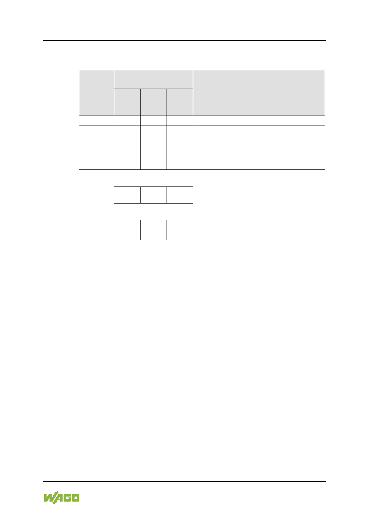
Table 1: Revision History
Docu-
Valid From
Device Version
Firm-
Hard-
Firm-
loader
1.0.0
01
01
01
First issue
1.0.1
01
01
01
• Section 5 “Mounting” changed:
browser added.
1.1.0
762-3000:
• In section 3 “Device Description“ ship
added.
01
01
01
762-3001, -3002, -3003:
01
03
01
762-300X Web Panels
1.2 Revision History
ment
Version
ware
ware
ware-
Description of Change
The included clamping elements must be
used.
• In section 8.5.4 notes on the web
approval DNV-GL added.
• In section 5 “Mounting“ sub-section
“Mounting in Compliance with VESA
Standard“ changed.
• In section 7 “Commissioning“ subsection “Removing the Protection Film“
1.3 Copyright
This Manual, including all figures and illustrations, is copyright-protected. Any
further use of this Manual by third parties that violate pertinent copyright
provisions is prohibited. Reproduction, translation, electronic and phototechnical
filing/archiving (e.g., photocopying) as well as any amendments require the
written consent of WAGO Kontakttechnik GmbH & Co. KG, Minden, Germany.
Non-observance will involve the right to assert damage claims.
Manual
Version 1.1.0
Page 10
10 Notes about this Documentation e!DISPLAY 7300T
762-300X Web Panels
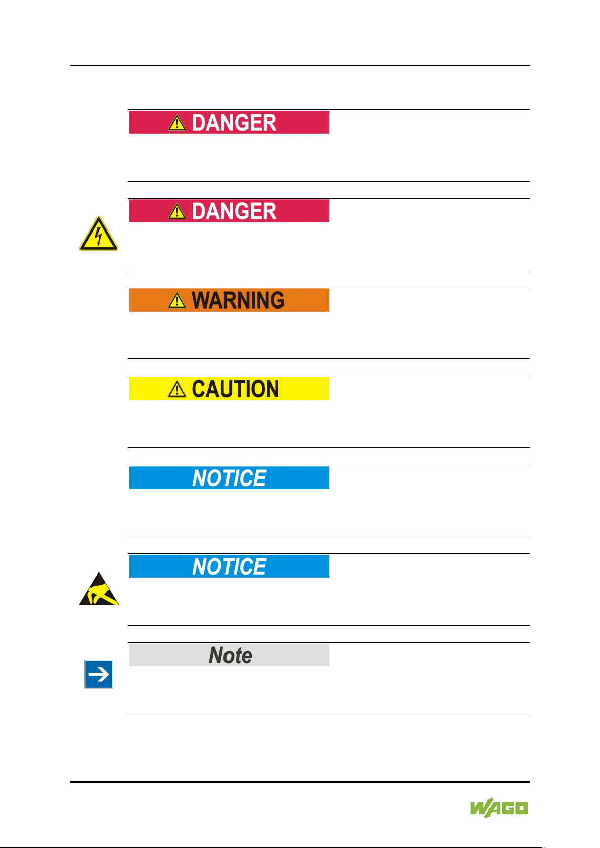
1.4 Symbols
Personal Injury!
Indicates a high-risk, imminently hazardous situation which, if not avoided, will
result in death or serious injury.
Personal Injury Caused by Electric Current!
Indicates a high-risk, imminently hazardous situation which, if not avoided, will
result in death or serious injury.
Personal Injury!
Indicates a moderate-risk, potentially hazardous situation which, if not avoided,
could result in death or serious injury.
Personal Injury!
Indicates a low-risk, potentially hazardous situation which, if not avoided, may
result in minor or moderate injury.
Damage to Property!
Indicates a potentially hazardous situation which, if not avoided, may result in
damage to property.
Damage to Property Caused by Electrostatic Discharge (ESD)!
Indicates a potentially hazardous situation which, if not avoided, may result in
damage to property.
Important Note!
Indicates a potential malfunction which, if not avoided, however, will not result in
damage to property.
Manual
Version 1.1.0
Page 11

e!DISPLAY 7300T Notes about this Documentation 11
762-300X Web Panels
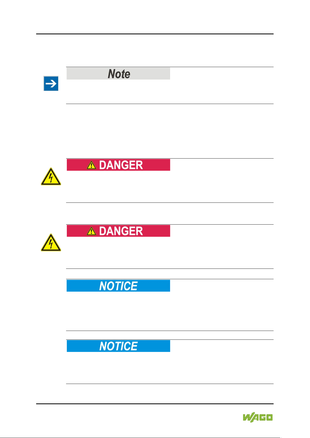
Additional Information:
Refers to additional information which is not an integral part of this
documentation (e.g., the Internet).
Manual
Version 1.1.0
Page 12

12 Notes about this Documentation e!DISPLAY 7300T
Table 2: Number Notation
Number Code
Example
Note
Decimal
100
Normal notation
Hexadecimal
0x64
C notation
Binary
'100'
'0110.0100'
In quotation marks, nibble separated
with dots (.)
Table 3: Font Conventions
Font Type
Indicates
italic
Names of paths and data files are marked in italic-type.
Menu
Menu items are marked in bold letters.
e.g.: Save
>
A greater-than sign between two names means the selection of a
e.g.: File > New
Input
Designation of input or optional fields are marked in bold letters,
Start of measurement range
“Value”
Input or selective values are marked in inverted commas.
Start of measurement range
[Button]
Pushbuttons in dialog boxes are marked with bold letters in square
e.g.: [Input]
[Key]
Keys are marked with bold letters in square brackets.
e.g.: [F5]
762-300X Web Panels
1.5 Number Notation
1.6 Font Conventions
e.g.: C:\Program Files\WAGO Software
menu item from a menu.
e.g.:
e.g.: Enter the value “4 mA” under
brackets.
.
Manual
Version 1.1.0
Page 13

e!DISPLAY 7300T Important Notes 13
762-300X Web Panels
2 Important Notes
This section includes an overall summary of the most important safety
requirements and notes that are mentioned in each individual section. To protect
your health and prevent damage to devices as well, it is imperative to read and
carefully follow the safety guidelines.
2.1 Legal Bases
2.1.1 Subject to Changes
WAGO Kontakttechnik GmbH & Co. KG reserves the right to provide for any
alterations or modifications. WAGO Kontakttechnik GmbH & Co. KG owns all
rights arising from the granting of patents or from the legal protection of utility
patents. Third-party products are always mentioned without any reference to
patent rights. Thus, the existence of such rights cannot be excluded.
2.1.2 Personnel Qualification
All sequences implemented on Series 762 devices may only be carried out by
electrical specialists with sufficient knowledge in automation technology. These
specialists must be familiar with the current standards and guidelines for the
devices and the automated environments.
All changes to the controller shall always be performed by qualified personnel
with sufficient skills in PLC programming.
2.1.3 Use of e!DISPLAYS 7300 in Compliance with Underlying
Provisions
e!DISPLAYS 7300 are suitable for use in the area of control and automation.
Their use extends beyond residential and commercial areas, as well as industrial
areas. Technical data must be observed for all types of applications.
2.1.4 Technical Condition of Specified Devices
The devices to be supplied ex works are equipped with hardware and software
configurations, which meet the individual application requirements. These
modules contain no parts that can be serviced or repaired by the user. The
following actions will result in the exclusion of liability on the part of WAGO
Kontakttechnik GmbH & Co. KG:
• Repairs,
• Changes to the hardware or software that are not described in the
operating instructions,
• Improper use of the components.
Manual
Version 1.1.0
Page 14
14 Important Notes e!DISPLAY 7300T
762-300X Web Panels
Further details are given in the contractual agreements. Please send your
request for modified and new hardware or software configurations directly to
WAGO Kontakttechnik GmbH & Co. KG.
Pixel error in TFT display
Any pixel errors of the TFT display due to production reasons do not represent
grounds for complaint!
2.2 Safety Advice (Precautions)
For installing and operating purposes of the relevant device to your system the
following safety precautions shall be observed:
Do not work when devices are energized!
High voltage can cause electric shock or burns.
Always disconnect the power supply from those parts of the system on which you
wish to mount or remove the device!
Use SELV power source only!
The device must only be powered from a SELV (Safety Extra Low Voltage)
power source complying with the limited power source (LPS) requirements per
DIN EN 60950-1.
Consider the IP protection type!
The device is an open unit whose back side is IP20 protected, only. If the
operating environment does not fulfill these requirements you have to install the
device into cabinet resp. housing. Then a maximum protection type IP65 can be
achieved depending on the cabinet resp. housing.
Replace defective or damaged devices!
Replace defective or damaged device/module (e.g., in the event of deformed
contacts), since the long-term functionality of device/module involved can no
longer be ensured.
Manual
Version 1.1.0
Page 15
e!DISPLAY 7300T Important Notes 15
762-300X Web Panels
Protect the components against materials having seeping and insulating
properties!
The components are not resistant to materials having seeping and insulating
properties such as: aerosols, silicones and triglycerides (found in some hand
creams). If you cannot exclude that such materials will appear in the component
environment, then install the components in an enclosure being resistant to the
above-mentioned materials. Clean tools and materials are imperative for
handling devices/modules.
Clean only with permitted materials!
Clean housing and soiled contacts with propanol.
Do not use any contact spray!
Do not use any contact spray. The spray may impair contact area functionality in
connection with contamination.
Do not use in telecommunication circuits!
Only use devices equipped with ETHERNET or RJ-45 connectors in LANs.
Never connect these devices with telecommunication networks.
Avoid electrostatic discharge!
The devices are equipped with electronic components that may be destroyed by
electrostatic discharge when touched. Please observe the safety precautions
against electrostatic discharge per DIN EN 61340-5-1/-3. When handling the
devices, please ensure that environmental factors (personnel, work space and
packaging) are properly grounded.
Manual
Version 1.1.0
Page 16

16 Important Notes e!DISPLAY 7300T
762-300X Web Panels
2.3 Special Use Conditions for ETHERNET Devices
If not otherwise specified, ETHERNET devices are intended for use on local
networks. Please note the following when using ETHERNET devices in your
system:
• Do not connect control components and control networks to an open
network such as the Internet or an office network. WAGO recommends
putting control components and control networks behind a firewall.
• Limit physical and electronic access to all automation components to
authorized personnel only.
• Change the default passwords before first use! This will reduce the risk of
unauthorized access to your system.
• Regularly change the passwords used! This will reduce the risk of
unauthorized access to your system.
• Regularly perform threat analyses. You can check whether the measures
taken meet your security requirements.
• Use “defense-in-depth” mechanisms in your system's security configuration
to restrict the access to and control of individual products and networks.
Manual
Version 1.1.0
Page 17
e!DISPLAY 7300T Device Description 17
762-300X Web Panels
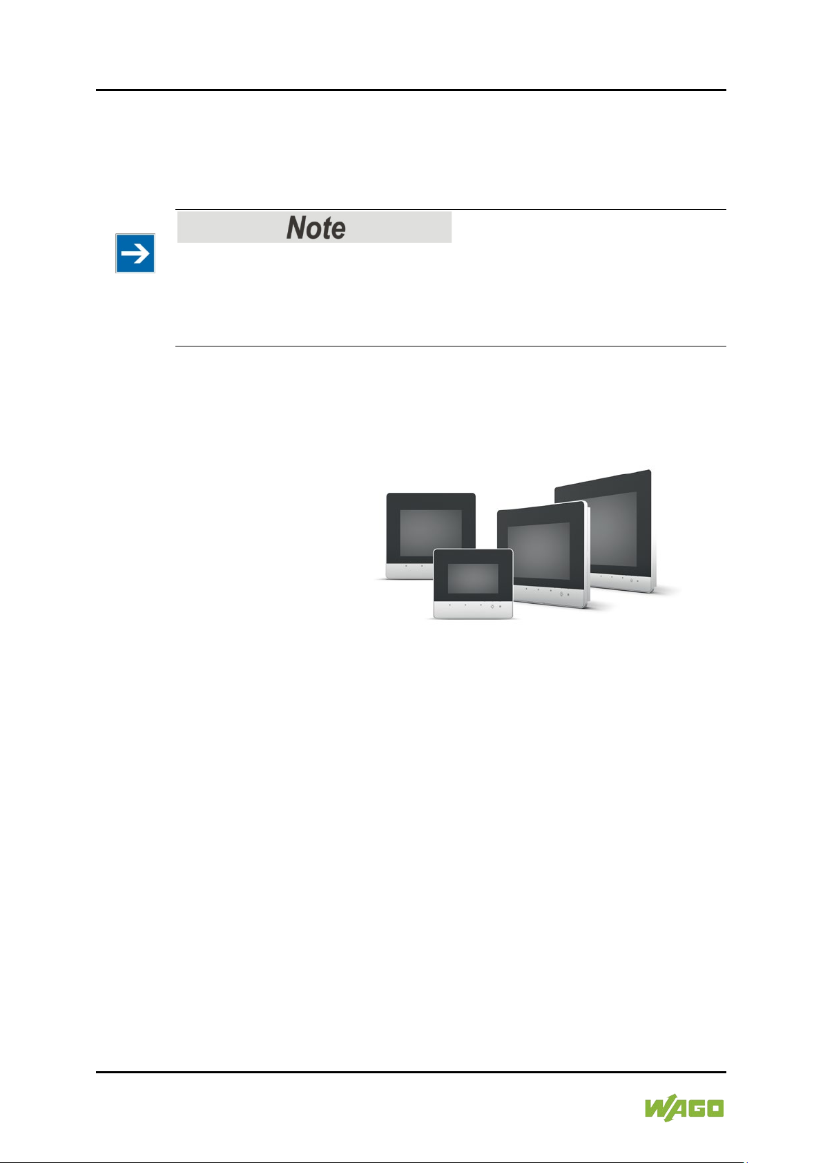
3 Device Description
Specifically configured as a Web browser, the Web Panel (WP) directly connects
to controllers with their own Web server.
The e!RUNTIME and CODESYS V2 Web visualization has been specifically
optimized for the Web Panel.
ETHERNET is used for communication.
The following Web panels are available:
• 762-3000, e!DISPLAY 7300T – WP 4.3 480×272 PIO1
• 762-3001, e!DISPLAY 7300T – WP 5.7 640×480 PIO1
• 762-3002, e!DISPLAY 7300T – WP 7.0 800×480 PIO1
• 762-3003, e!DISPLAY 7300T – WP 10.1 1280×800 PIO1
Manual
Version 1.1.0
Page 18
18 Device Description e!DISPLAY 7300T
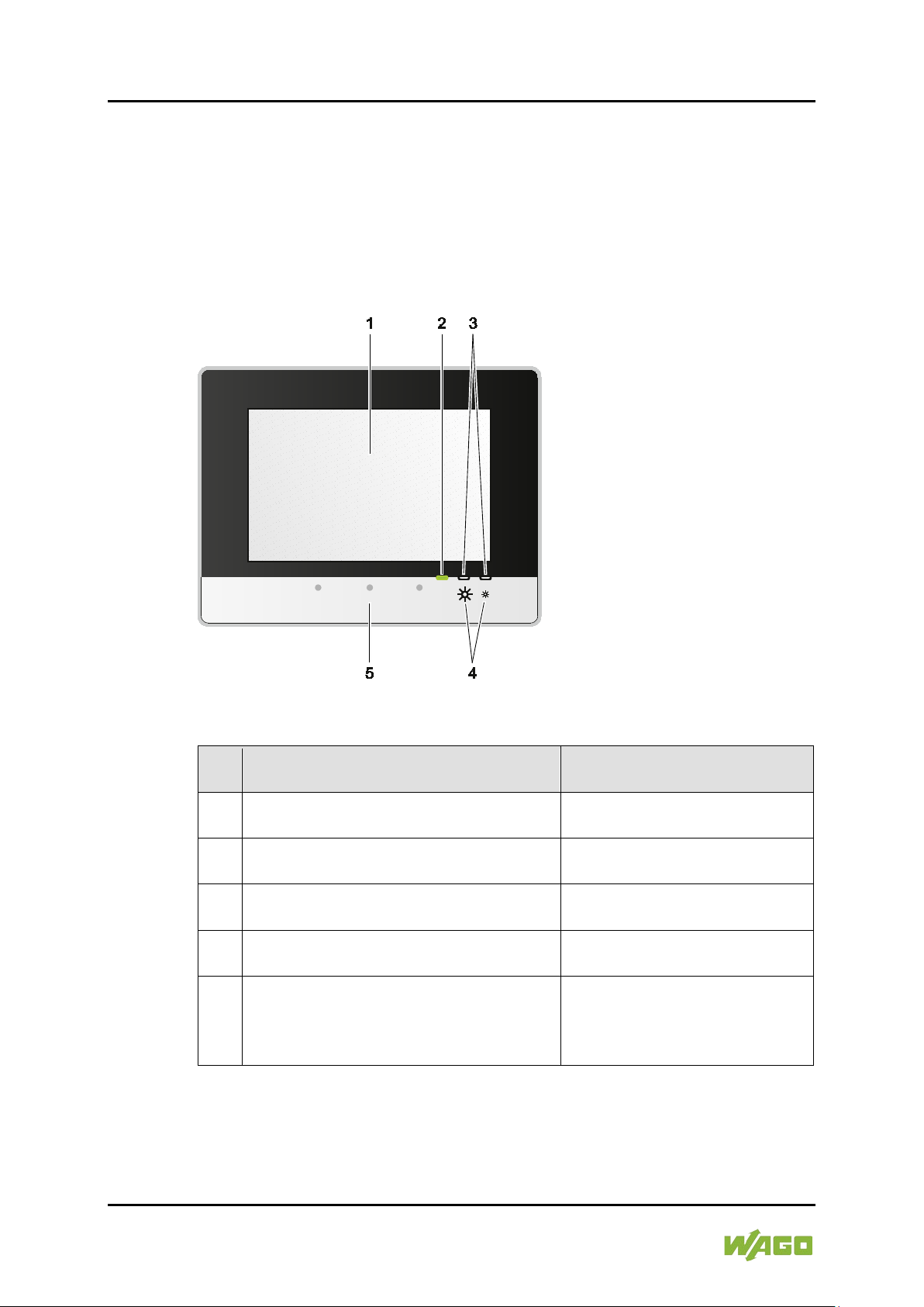
Table 4: Legend for Figure “Front View”
Pos
.
Description
Details See Section
1
Touch screen
“Device Description” >
2
Status LED
“Device Description” >
“Display Elements”
3
Feedback LEDs for brightness buttons
“Device Description” > “Display
Elements”
4
Brightness buttons
“Device Description” >
5
Motion sensor
“Device Description” >
“Screensaver”
762-300X Web Panels
3.1 Views
3.1.1 Front View
The touch screen, as well as display and operating elements are located on the
front.
Figure 1: Front View (Example of 762-3002)
“Touch Screen”
“Operating Elements”
“Touch Screen” and
“Running Web Visualization” >
Manual
Version 1.1.0
Page 19
e!DISPLAY 7300T Device Description 19
762-300X Web Panels
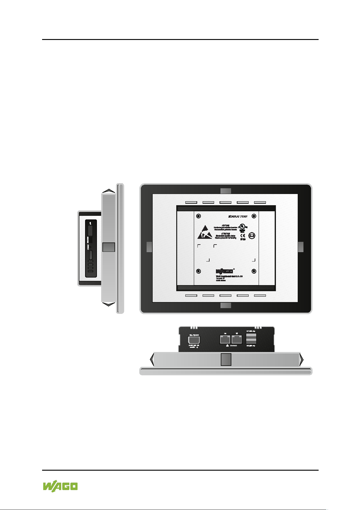
3.1.2 Other Views
There are four M4 threaded holes on the back for VESA mounting, 4 mounting
clips, one earth screw or contact and the device labeling. For details, see section
“Mounting” and “Device Description” > “Labeling”.
There are 5 connectors on the bottom. For details, see section “Device
Description” > “Connectors”.
The “CFG/RST” button and memory card slot are on the left side. For details,
see section “Device Description” > “Operating Elements” and > “Connectors”.
The “SERVICE” configuration interface has no function.
When installed, the specified function elements are not accessible from the front.
Figure 2: Other Views (Example of 762-3002)
Manual
Version 1.1.0
Page 20
20 Device Description e!DISPLAY 7300T
762-300X Web Panels
3.2 Touch Screen
The touch screen displays the Web visualization and processes inputs from the
system operator by hand or pen.
It is a resistive TFT LCD with LED backlight that recognizes swiping and scrolling
with one touch point.
Because it is a resistive touch screen, a certain pressure is exerted on the foil
during input.
A motion sensor is built in to recognize linear gestures. The system automatically
calibrates the sensor every 30 minutes. In this way, any change of location is
detected and objects are detected that are always nearby.
For technical data, please see section “Technical Data”.
Bright image information!
If the screen displays an image with bright image information, the pixels may stay
longer translucent than other screen regions that display changing content /
brightness. However, you should always seek a balance between switching
ON/OFF and a display that is always on.
Manual
Version 1.1.0
Page 21
e!DISPLAY 7300T Device Description 21
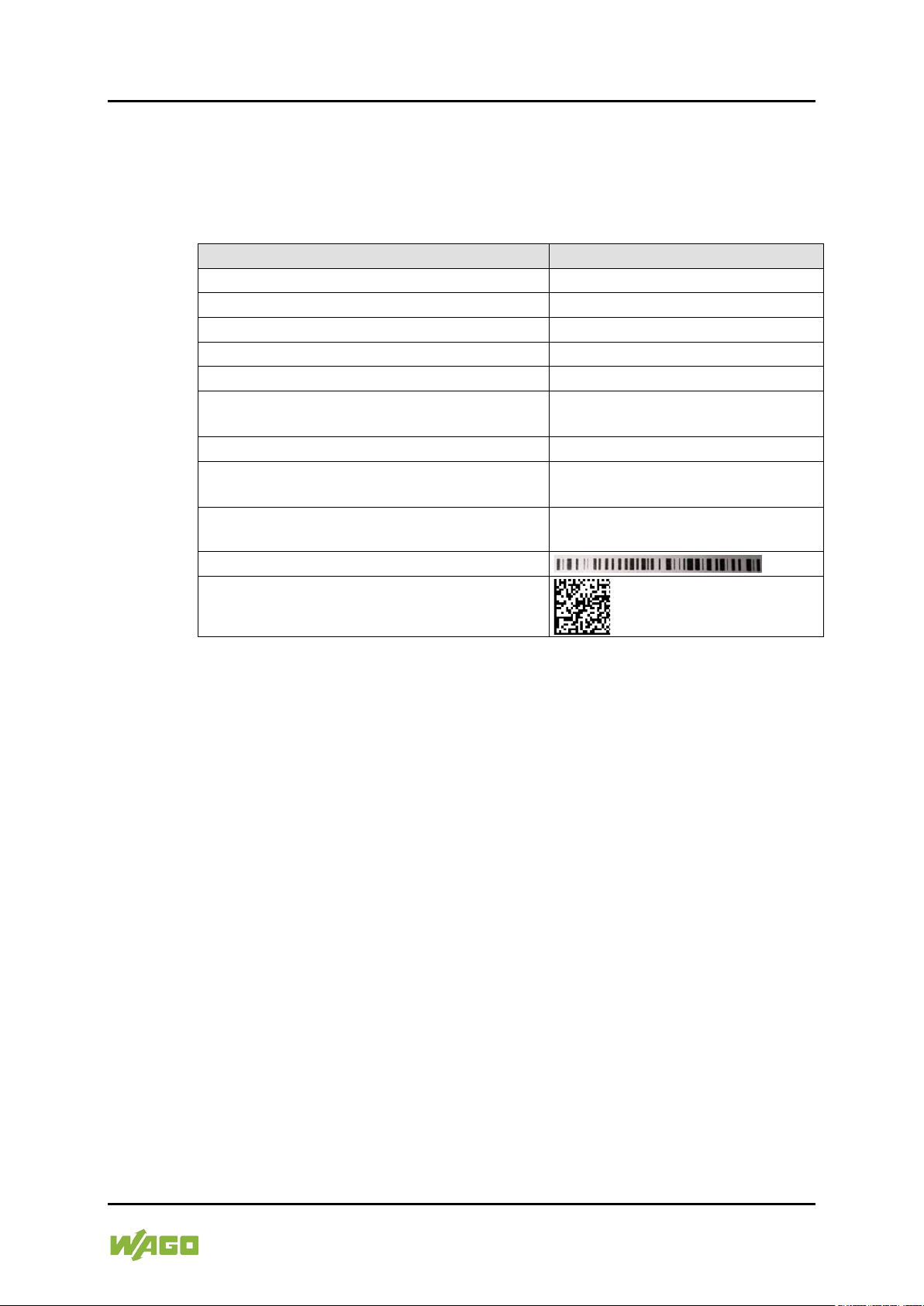
Table 5: Type Plate
Field
Example
Item Number
ITEM NO.: 0762-3000
Item description 1
e!DISPLAY 7300T
Item description 2
WP 4.3 480x272 PIO1
Control number
24723.5001
Date of manufacture (year – month)
2015-08
Release indexes (2 digits ea.): 1. Firmware,
2. Hardware, 3. Firmware loader
010101
Power consumption
Pmax.=4 W
Supply voltage
U=SELV 24V DC
(−25% … +30%)
Serial number
SN:37SUN31564010260275035+00
00000002239054
Barcode
QR code
762-300X Web Panels
3.3 Labeling
The type plate is attached to the back and contains the following information
about the device:
Manual
Version 1.1.0
Page 22
22 Device Description e!DISPLAY 7300T
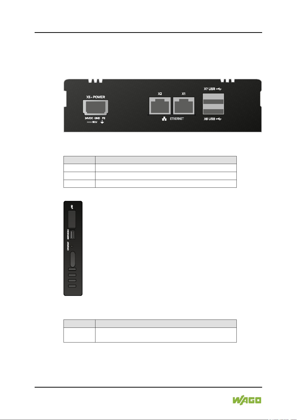
Table 6: Legend for Figure “Connectors on the Bottom”
Connector
Function
X1 and X2
ETHERNET interfaces with LED indicators
X5
Supply voltage infeed
X6 and X7
USB 2.0 host interfaces
Table 7: Legend for Figure “Connectors on the Left Side”
Connector
Function
microSD
Slot for microSD and microSDHC cards with cap,
sealable
762-300X Web Panels
3.4 Connectors
The connectors are on the bottom and left side.
Figure 3: Connectors on the Bottom (Example of 762-3002)
Figure 4: Connectors on the Left Side (Example of 762-3002)
Manual
Version 1.1.0
Page 23

e!DISPLAY 7300T Device Description 23
Table 8: X5 Pin Assignment
Pin
Description
Assignment
1
24VDC
Supply voltage: +24 VDC
2
GND
Reference potential 0V (ground)
3
FE
Functional earth
762-300X Web Panels
3.4.1 “X1” and “X2” ETHERNET Interfaces
The ETHERNET interfaces are RJ-45 ports. The orange LED illuminates when
there is a LINK and the green one blinks during data transfer.
The connectors and cables meet category 5e requirements and guidelines for
ETHERNET interfaces.
The integrated 10/100Mbit ETHERNET switch supports Auto-MDI(X).
A crossover or patch cable can be used.
3.4.2 “X5” Supply Voltage
Connect the supply voltage to the X5 connector. For this, use the included 734103 female connector featuring three CAGE CLAMP
For more information about the supply voltage, see section “Device Description”
> “Technical Data”.
3.4.3 “X6” and “X7” USB-2.0 Interfaces
The USB 2.0 host interfaces are designed with 4-pin type A sockets. Each
interface can supply max. 500 mA.
The connectors comply with the USB 2.0 specification.
Keyboards or mice can be connected as alternative input devices or up to 2 USB
memory devices. These USB devices must be connected before power ON.
</dg_
3.4.4 “microSD” Memory Card Slot
®
connections.
The panel is equipped with a laterally mounted slot for microSD and microSDHC
memory cards.
microSD (max. 2 GB) and microSDHC (max. 32 GB) cards tested by WAGO can
be used.
Use only WAGO memory cards!
Proper function and performance cannot be ensured when using SD/SDHC
memory cards not approved by WAGO.
Manual
Version 1.1.0
Page 24

24 Device Description e!DISPLAY 7300T
762-300X Web Panels
Pay attention to the memory card preformatting!
Please note that memory cards ≤ 2 GB are often formatted with the “FAT16” file
system type and can generate up to 512 entries in the root directory. For more
than 512 entries, generate them in a subdirectory or format the memory card as
“FAT32.
Manual
Version 1.1.0
Page 25

e!DISPLAY 7300T Device Description 25
762-300X Web Panels
3.5 Real-Time Clock
The real-time clock RTC is installed internally and not accessible. It is for internal
use only.
Deviation/accuracy
The deviation is less than ± 4 sec/day with an ambient temperature of 25 °C.
Power reserve
The clock continues to run min. 35 days (corresponds to 840 hours) at 25 °C
after shutting off the power supply.
After more than 35 days without a power supply, a clock setting dialog appears to
enter the time again. The appearance of the dialog can be switched ON or OFF
in the configuration.
There is no battery for buffering.
Resolution
The resolution of the clock for date and time is 1 sec.
Date and time are supplied and queried by the application.
Manual
Version 1.1.0
Page 26

26 Device Description e!DISPLAY 7300T
Table 9: Status LED
LED Display
Message
Green, steady
The panel is ready to operate.
Red, flashing
There is an error.
(The specific error message is displayed.)
Blue, flashing
There is a connection error to the controller. No
communication
762-300X Web Panels
3.6 Display Elements
3.6.1 Status LED
There is a 3-color status LED on the front for displaying operating and error
messages.
The indicators are explained as follows:
3.6.2 Feedback LEDs for the Brightness Buttons
Two capacitive buttons with visual feedback from two white LEDs are used to set
the display brightness.
Manual
Version 1.1.0
Page 27

e!DISPLAY 7300T Device Description 27
762-300X Web Panels
3.7 Operating Elements
The panel is primarily operated from the touch screen. In addition, there are also
2 capacitive buttons for brightness control on the front.
The “CFG/RST” button is on the left side for configuring the panel.
See also section “Running Web Visualization” or “Performing Service”.
External USB devices, e.g., keyboard and mouse, can also be used to operate
the panel.
Manual
Version 1.1.0
Page 28
28 Device Description e!DISPLAY 7300T
762-300X Web Panels
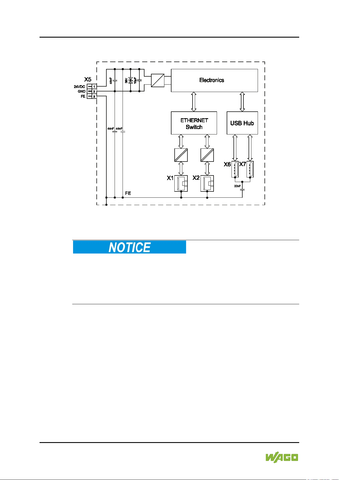
3.8 Schematic Diagram
Figure 5: Schematic Diagram
Do not use USB devices connected to earth!
USB interface shielding is not earthed directly, rather via interferencesuppression capacitor. Only keyboards, mice and USB memory sticks may be
connected. Do not connect devices that are earthed, e.g., printers, because they
bridge the interference-suppression capacitors and thus interference immunity is
reduced.
Manual
Version 1.1.0
Page 29

e!DISPLAY 7300T Device Description 29
Table 10: Technical Data ‒ Device
Front panel
Anodized aluminum (plastic at 4.3”),
polyester film
Housing material
Anodized aluminum
Dimensions
4.3”: 155 × 135 × 58 mm
5.7”: 172 × 163 × 58 mm
7.0”: 213 × 167 × 58 mm
10.1”: 293 × 223 × 58 mm
Mounting panel cutout (width × height)
4.3”: 140 × 120 mm
5.7”: 157 × 148 mm
7.0”: 198 × 152 mm
10.1”: 278 × 208 mm
Mounting panel thickness
2 … 6 mm
All-round clearance for ventilation and
100 mm
Mounting
4.3” with 4 clamping elements, 5.7” and
or VESA mount (4 × M4 × 8)
Weight
4.3”: 800 g
5.7”: 1000 g
7.0”: 1200 g
10.1”: 2050 g
IP degree of protection
or housing
• For VESA mounting
• IP20 (protection against foreign
no protection against water)
Protection class
SK III
Overvoltage category
II
Pollution degree
2
762-300X Web Panels
3.9 Technical Data
3.9.1 Device
(width × height × depth)
cable routing
• For installation in a control cabinet or
housing
7.0” with 8 and 10.1” with 10 clamping
elements
• Up to IP65/NEMA4 (dust tight and
water jets), depending on the degree
of protection of the control cabinet
objects ≥ 12.5 mm,
Manual
Version 1.1.0
Page 30
30 Device Description e!DISPLAY 7300T
Table 11: Technical Data ‒ Climatic Environmental Conditions
Permissible ambient temperatures
4.3”
0 °C … 55 °C
0 °C … 55 °C
0 °C … 55 °C
Permissible storage temperature
−20 °C ... +80 °C Please refer to the
chart below!
Relative humidity
(without condensation)
10 % ... 90 % Please refer to the chart
below!
Operating altitude
0 m … 2000 m
762-300X Web Panels
3.9.2 Climatic Environmental Conditions
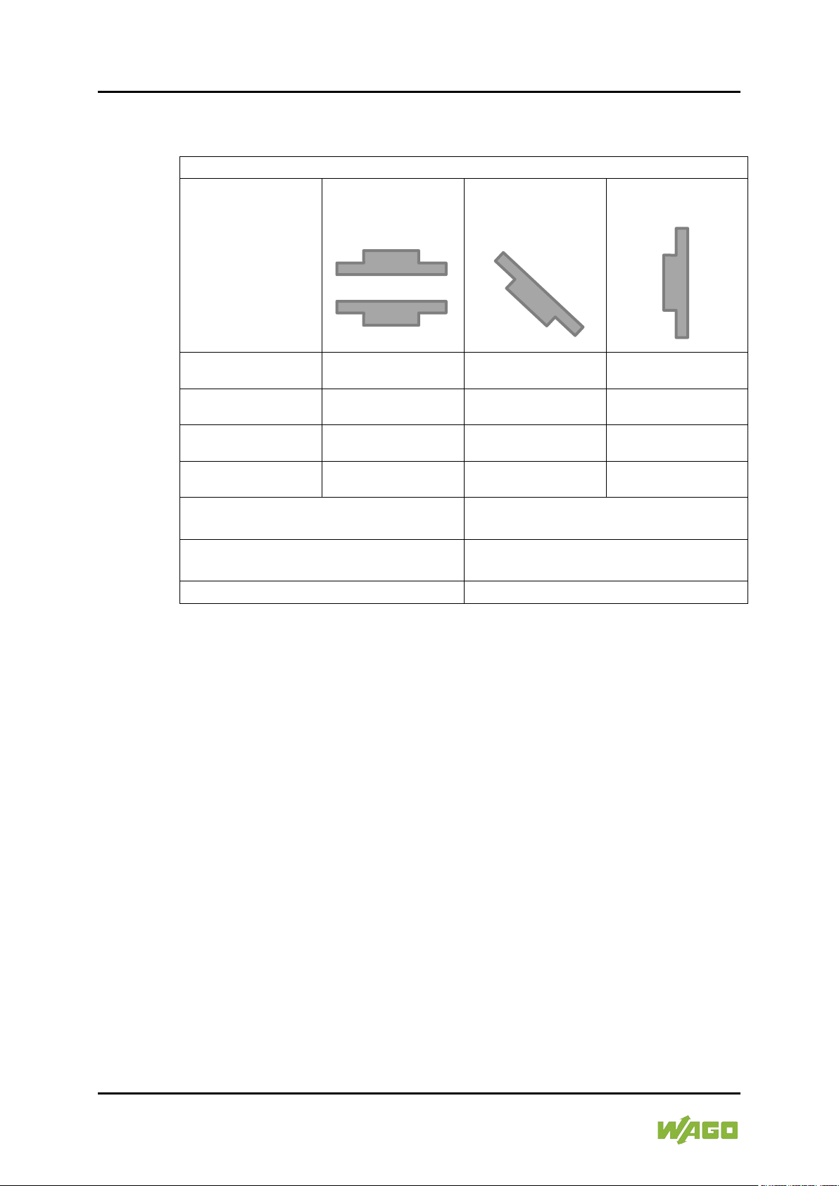
Mounting position
horizontal
Mounting position
± 45°
Mounting position
vertical
or
5.7” 0 °C … 55 °C 0 °C … 55 °C 0 °C … 55 °C
7.0” 0 °C … 55 °C 0 °C … 55 °C 0 °C … 55 °C
10.1” 0 °C … 50 °C 0 °C … 50 °C 0 °C … 55 °C
The permissible storage temperature and relative humidity that occurs are
interdependent. The chart below shows the relationship. The permitted range is
shaded in gray.
Example 1:
With relative humidity of 90 %, the device can be stored at a maximum
temperature of 60 °C.
Example 2:
With a storage temperature of 68 °C, the maximum relative humidity can be 60
%.
Manual
Version 1.1.0
Page 31

e!DISPLAY 7300T Device Description 31
Table 12: Technical Data ‒ Power Supply
Operating Voltage
SELV 24 VDC (−25 % ... +30 %)
with reverse polarity protection
Max. current and power consumption
4.3”: 170 mA, 4.0 W
5.7”: 210 mA, 5.0 W
7.0”: 290 mA, 7.0 W
10.1”: 390 mA, 9.5 W
Max. current consumption across the
4.3”: 185 mA/430 mA
5.7”: 230 mA/520 mA
7.0”: 330 mA/640 mA
10.1”: 520 mA/820 mA
Max. power consumption across the
4.3”: 4.0 W /8.6 W
5.7”: 5.0 W/10.2 W
7.0”: 7.3 W/12.2 W
10.1”: 9.9 W/15.5 W
Connecting cable
Max. 3 m to the power supply,
3 × 0.14 … 1.5 mm2 (AWG 25 … 14)
762-300X Web Panels
Figure 6: Dependence between Storage Temperature and Relative Humidity
3.9.3 Power Supply
at 24 V, without external USB devices
entire voltage range,
without/with external USB devices
entire voltage range,
without/with external USB devices
(safety extra-low voltage)
Manual
Version 1.1.0
Page 32

32 Device Description e!DISPLAY 7300T
Table 13: Technical Data ‒ Touch Screen 4.3” (109 mm)
Display type
TFT, Wide Viewing Angle
Screen size (diagonal)
4.3” (109 mm)
Aspect
16:9
Display colors
16 million colors
Graphics resolution
480 × 272 pixels
Contrast ratio
600:1
Viewing angle, horizontal/vertical
80 ° / 80 °
Brightness
Max. 500 cd/m², settable
HBT*
50,000 hrs.
Durability
100,000 activations with touch pen
Table 14: Technical Data ‒ Touch Screen 5.7” (145 mm)
Display type
TFT, Wide Viewing Angle
Screen size (diagonal)
5.7” (145 mm)
Aspect
4:3
Display colors
262,000 colors
Graphics resolution
640 × 480 pixels
Contrast ratio
300:1
Viewing angle, horizontal/vertical
80 ° / 80 °
Brightness
Max. 630 cd/m², settable
HBT*
30,000 hrs.
Durability
100,000 activations with touch pen
762-300X Web Panels
3.9.4 Touch Screen
* The HBT (Half Brightness Time) defines the decrease in “LED chip brightness”
by 50 % compared to the original brightness. This information applies to T = 25
± 2 °C and RH = 60 ± 10 %.
* The HBT (Half Brightness Time) defines the decrease in “LED chip brightness”
by 50 % compared to the original brightness. This information applies to T = 25
± 2 °C and RH = 60 ± 10 %.
Manual
Version 1.1.0
Page 33

e!DISPLAY 7300T Device Description 33
Table 15: Technical Data ‒ Touch Screen 7.0” (180 mm)
Display type
TFT, Wide Viewing Angle
Screen size (diagonal)
7.0” (180 mm)
Aspect
16:9
Display colors
16 million colors
Graphics resolution
800 × 480 pixels
Contrast ratio
800:1
Viewing angle, horizontal/vertical
89 ° / 89 °
Brightness
Max. 450 cd/m², settable
HBT*
30,000 hrs.
Durability
100,000 activations with touch pen
Table 16: Technical Data ‒ Touch Screen 10.1” (257 mm)
Display type
TFT, Wide Viewing Angle
Screen size (diagonal)
10.1” (257 mm)
Aspect
16:9
Display colors
16 million colors
Graphics resolution
1280 × 800 pixels
Contrast ratio
800:1
Viewing angle, horizontal/vertical
85 ° / 85 °
Brightness
Max. 800 cd/m², settable
HBT*
70,000 hrs.
Durability
100,000 activations with touch pen
762-300X Web Panels
* The HBT (Half Brightness Time) defines the decrease in “LED chip brightness”
by 50 % compared to the original brightness. This information applies to T = 25
± 2 °C and RH = 60 ± 10 %.
* The HBT (Half Brightness Time) defines the decrease in “LED chip brightness”
by 50 % compared to the original brightness. This information applies to T = 25
± 2 °C and RH = 60 ± 10 %.
Manual
Version 1.1.0
Page 34

34 Device Description e!DISPLAY 7300T
Table 17: Technical Data ‒ Hardware
Processor
ARM® Cortex™ A8, 32 Bit, 600 MHz
RAM/Flash
512 MB / 1024 MB
External memory extension
microSD card (max. 2 GB) or
Table 18: Technical Data ‒ Software
Operating system
Linux® 3.6.11
Web visualization
e!RUNTIME
Web browser
QtWebkit from Qt 4.8.6
Web server
Lighttp 1.4.35
Java Runtime
Oracle Java SE embedded,
Configuration software
WAGO WBM
Table 19: Technical Data ‒ Interfaces
USB interfaces
2 × USB 2.0 host (type A) socket,
connecting cable max. 3 m
ETHERNET interfaces
2 × RJ-45 socket, with switch, 10/100
crossover, max. 100 m
762-300X Web Panels
3.9.5 Hardware
(“microSD” slot)
3.9.6 Software
3.9.7 Interfaces
microSDHC card (max. 32 GB)
Version 7, Update 4
480 Mbit/s,
Mbit/s, protocols DHCP, DNS, FTP,
FTPS, HTTP, HTTPS and SSH,
connecting cables twisted pair SF-UTP,
100 Ohms, category 5e, patch or
Manual
Version 1.1.0
Page 35

e!DISPLAY 7300T Device Description 35
Conformity Marking
762-300X Web Panels
3.10 Approvals
The following approvals have been granted to 762-300X panels:
UL61010-1
CULUS
No VESA mounting in the field of DNV GL applications!
If a DNV GL approval is required for your application you must install the panel
into cabinet resp. housing. Mounting in compliance with VESA standard is not
permitted!
DNV GL
Detailed information regarding approvals
Detailed information regarding approvals can be found at:
https://www.wago.com
<item no.>
3.11 Standards and Guidelines
762-300X panels meet the following requirements on emission and immunity of
interference:
EMC CE-Immunity to interference EN 61000-6-2
EMC CE-Emission of interference EN 61000-6-4
Manual
Version 1.1.0
Page 36

36 Function Description e!DISPLAY 7300T
762-300X Web Panels
4 Function Description
Featuring an integrated Web browser, the Web Panel connects to controllers with
their own Web server.
When operating the machine resp. system to be controlled, the CODESYS “Web
Visualization” application is used to display the programmed visualization.
ETHERNET is used for communication with the controller.
The “Web-Based Management WBM” software is used at startup.
4.1 Web Browser
The integrated Web browser displays the controller websites.
Up to 10 controllers can be configured in the WBM. The “PLC List” is used to
select a controller and to launch his Web visualization directly.
Manual
Version 1.1.0
Page 37

e!DISPLAY 7300T Function Description 37
762-300X Web Panels
The following can be configured as the start page:
• The WBM
• the selection list “PLC List”
• or the Web visualization of a specific controller directly.
The Web browser can display Web pages via encrypted connections (HTTPS).
The virtual keyboard opens automatically when an input field is actuated. The
user can use the “Switch keyboard” button to switch between levels (letters and
numbers).
The user can choose between the “virtual keyboard” and “CODESYS numpad
and keypad” in a CODESYS visualization.
4.2 Connection Monitoring
If a CODESYS visualization connection is interrupted, an error message is
displayed and the panel automatically attempts to restore the connection
(reconnect) every 10 seconds.
4.3 WBM for Configuration/Parameterization
The Web-Based Management (WBM) provides an interface for configuring or
parameterizing the panel optimized for the touch-sensitive screen. The WBM can
be called up from the panel directly or on the engineering PC.
The WBM has settings for:
• Information
• Application
• Display
• Networking
• Firewall
• Ports and Services
• Administration
• Clock
A detailed description of all available elements and functions is available in
Section 7 “Commissioning”.
Manual
Version 1.1.0
Page 38

38 Function Description e!DISPLAY 7300T
WBM user
Linux® user
admin
admin
Web-Based Management (WBM)
X X
Linux® console
X X X
Telnet
X X X
FTP
X X X
FTPS
X X X
SSH
X X X
762-300X Web Panels
4.4 Network
4.4.1
Interface Configuration
The X1 and X2 ETHERNET interfaces of the panel are connected to an internal
3-port switch, whose third port is connected to the CPU. The “Configuration Type”
is set to “DHCP” by default. The TCP/IP settings such as IP address or subnet
mask apply to both X1 and X2.
4.4.2 Network Security
4.4.2.1 Users and Passwords
There are several user groups in the panel that can be used for different
services.
A default password is set for all users. We strongly recommend changing these
passwords on startup!
4.4.2.2 Services and Users
All password-protected services and their associated users are listed in the
following table.
Service
4.4.2.3 WBM User Group
The Web-Based Management (WBM) has its own user management. The users
in this system are isolated from the other user groups in the system for security
reasons.
At initial start-up, you are prompted in the WBM to change the password when
logging in as an Admin user.
This does not change the passwords for the Linux® “root” and “admin” users!
user
root
user
Manual
Version 1.1.0
Page 39

e!DISPLAY 7300T Function Description 39
Table 20: WBM Users
User
Permissions
Default Password
admin
all (administrator)
wago
user
limited
user
Table 21: Linux® Users
User
Special
Feature
Home Directory
Default Password
root
superuser
/root
wago
admin
/home/admin
wago
762-300X Web Panels
4.4.2.4 Linux® User Group
The Linux® user group includes the actual users of the operating system who are
also used by most services. The passwords for these users are to be configured
via SSH terminal connection.
Example
The PuTTY SSH client is used via ETHERNET to change the default password
®
for the Linux
user “root”.
After launching putty.exe, “login as:” appears. Enter “root” and press [Enter]. You
are prompted to enter the password. Enter “wago” as the default password. You
are prompted to assign a “New password:”. Enter a unique password that meets
the required level of security and press [Enter]. You are prompted to “Retype
password:”. Enter your password again and press [Enter] to change the
password.
®
Repeat the process when logging in as a Linux
“admin” user.
Manual
Version 1.1.0
Figure 7: Example for Linux® Password
Page 40

40 Function Description e!DISPLAY 7300T
762-300X Web Panels
4.4.3 Network Configuration
4.4.3.1 Host Name/Domain Name
If the host name is not configured, the panel receives a default name based on
the last three values of the panel's MAC address, e.g., “e!DISPLAY-A1A2A3”.
The name applies as long as no host name is configured or no host name is
given to the panel by DHCP (to configure the panel, see section “Commissioning”
> “Configuring in the Web-Based Management (WBM)”). When the host name is
set, a host name supplied by a DHCP response is immediately active and
displaces the configured or default host name. If only the configured name should
apply, the network administrator must adjust the configuration of the active DHCP
server, so that no host name is passed in the DHCP response.
The default host name or the configured name is active again if the network
interfaces are set to static IP addresses or if a host name is not received via the
DHCP response.
A similar mechanism is used for a domain name as for the host name. The
difference is that a default domain name is not set. As long as a domain name is
not configured or supplied by DHCP, the domain name is empty.
4.4.3.2 Default Gateways
Two default gateways can be set for the panel in the TCP/IP configuration. A
network station transmits to a default gateway all network data packets for
systems outside of its local network. This gateway is responsible for the
appropriate routing of the data packets, so that they reach the target system.
A so-called metric is assigned to the default gateways that specifies with what
time delay, sometimes called cost factor, a data packet can be forwarded via the
gateway. If multiple default gateways are configured, the operating system
transmits the data packets to the default gateway configured with the lowest
metric. If this gateway is not accessible, an attempt is made to access the
gateway with the next higher metric. If several of the gateways have the same
metric, the gateway is determined randomly. If this gateway cannot transmit the
data packet, the data packet is sent simultaneously to all other gateways of the
same metric.
The metric of the configured default gateways can be specified for the panel. The
default value for the metric is 20. Besides the directly configured gateways, other
gateways can be set via DHCP responses so that more than two gateways are
possible. All gateways transferred via DHCP are assigned a permanent metric of
10. The DHCP gateways are thus normally given priority on account of their low
metric.
4.5 Memory Card Functions
The memory card is optional and is used as an additional memory range for the
internal memory or drive in the panel. Device settings and the panel's firmware
can be saved on the memory card.
Manual
Version 1.1.0
Page 41

e!DISPLAY 7300T Function Description 41
762-300X Web Panels
4.5.1 Backup
This function enables the data of the internal memory and device settings to be
saved on the memory card during operation.
The following options are available from the “Backup” function of the function
menu in the Web-Based Management:
• Settings
• System
The network, or when inserted, the memory card or USB memory can be
selected as the target medium.
The files of the internal drive are stored on the target medium in the directory
media/sd/copy and in the corresponding subdirectories. Information that does not
exist as files in the controller is saved in XML format in the media/sd/settings
directory.
The device settings and files of the internal drive are then saved on the target
medium.
4.5.2 Restore
This function is used to load the data and device settings from the memory card
to the internal memory during operation.
The following options are available from the “Restore” function of the function
menu in the Web-Based Management:
• Settings
• System
The network, or when inserted, the memory card or USB memory can be
selected as the source medium.
When loading the data, the files are copied from the directory media/sd/copy of
the source medium to the appropriate directories on the internal memory.
The device restarts if parameters change!
Note that the device loading the data executes a restart if parameters in the
internal drive are overwritten with different parameter settings from the memory
card.
Manual
Version 1.1.0
Page 42

42 Function Description e!DISPLAY 7300T
762-300X Web Panels
Data size may not be larger than the internal drive size!
Note that the size of data in the media/sd/copy directory may not exceed the total
size of the internal drive.
4.5.3 Create Image
This WBM function can be used to create a bootable copy of the system currently
booted. If the panel was started from the internal flash, a copy is written to the
memory card via the function menu > “Create Image”. If the panel was
started from the memory card, a copy is saved to the internal flash via the
function menu > “Create Image”. The existing image is deleted.
Manual
Version 1.1.0
Page 43

e!DISPLAY 7300T Function Description 43
762-300X Web Panels
4.6 Downloading Software
The panel has the option to install or update individual software packages. The
software packages are available from WAGO.
You can install them from your PC via WBM. See also section 7 “Commissioning”
> “Configuring in the Web-Based Management (WBM)” > “WBM Function Menu”.
4.7 Booting
Start Behavior
Manual
Version 1.1.0
Page 44

44 Function Description e!DISPLAY 7300T
762-300X Web Panels
Browser
CFG/RST Button
Pressing the CFG/RST at run-time opens the WBM.
Pressing the button at panel startup (power ON) prevents the normal auto start
and only the WBM starts. The button is not used to make any changes to the
settings.
Alternatively, you can also go to the WBM via the PLC list using a swipe gesture.
Manual
Version 1.1.0
Page 45

e!DISPLAY 7300T Function Description 45
762-300X Web Panels
Swipe Gesture
The swipe gesture (from the top of the screen downwards) opens a menu with 2
buttons: PLC List (incl. WBM) and screen cleaning.
The swipe gesture works when a browser is running (WebVisu, WBM, PLC List).
4.8 Font Upload
As delivered, three “Liberation Fonts” (freely available fonts) are preinstalled that
are largely identical to the Arial, Times New Roman and Courier New fonts from
Microsoft.
If you want to install other True Type fonts (file type .ttf) or remove existing fonts,
launch “Font Upload” in the WBM function menu.
In general, all fonts used in the visualization should be installed on the
engineering PC and on the panel.
Manual
Version 1.1.0
Page 46

46 Mounting e!DISPLAY 7300T
762-300X Web Panels
5 Mounting
Consider the IP protection type!
The device is an open unit whose back side is IP20 protected, only. If the
operating environment does not fulfill these requirements you have to install the
device into cabinet resp. housing. Then a maximum protection type IP65 can be
achieved depending on the cabinet resp. housing.
Avoid exposure to direct light!
Position the panel to avoid direct exposure to a strong light source, e.g., sunlight!
5.1 Assembly Guidelines/Standards
• DIN 60204 Electrical equipment of machines
• DIN EN 50178 Electronic equipment for use in power installations
(replacement for VDE 0160)
• EN 60439 Low-voltage switchgear and controlgear assemblies
5.2 Installation in Front Door or Housing
The panels are intended for installation that adheres to UL type 1, type 12 or type
4X, e.g., in a control cabinet’s front door or in an appropriate housing. To ensure
adequate cooling and a suitable cable route, a free space of 100 mm must be
available on all sides.
The permitted ambient temperature depends on the mounting position!
If the panel is not installed vertically, cooling is affected, i.e., maximum
permissible ambient temperature is reduced. For exact values, see section 3
“Device Description” > “Technical Data”.
The panels are mounted from the front of the cabinet into the provided cutout.
Press the panel into the cutout until the four mounting clips audibly engage.
To hold the panel securely in place and to achieve IP65 or a UL-NEMA4 degree
of protection (depending on the cabinet's protection class) you must also screw
the panel from behind into the door using the included 4, 8 or 10 clamping
elements. The following installation drawings must be observed.
Attach the clamping elements on positions 1 … 4 for 762-3000, positions 1 … 8
Manual
Version 1.1.0
Page 47

e!DISPLAY 7300T Mounting 47
Table 22: Positions of the Clamping Elements
Distance a
Distance b
762-3000
*
*
762-3001
38 mm
30 mm
762-3002
55 mm
29 mm
762-3003
28 mm
45 mm
* Positions Depend on Housing Design.
762-300X Web Panels
for 762-3001/-3002 and positions 1 … 10 for 762-3003. The tightening torque is
0.1 Nm for 762-3000 and 0.14 Nm for 762-3001 … -3003. This way, the seal
makes a uniform contact.
Figure 8: Mounting Clips and Positions of the Clamping Elements
Figure 9: Securing the Clamping Elements via Screw
Manual
Version 1.1.0
Page 48

48 Mounting e!DISPLAY 7300T
762-300X Web Panels
5.3 Mounting in Compliance with VESA Standard
In addition to installation in a cutout, the panel can also be mounted, e.g., on a
monitor stand, via four M4×8 screws (strength rating: 8.8). To support this, four
threaded holes are drilled in a 75 × 75 mm square arrangement at the rear of the
panel in compliance with the VESA MIS-D 75 C standard. Because the panel is
unprotected when pole-mounted, it only has an IP20 degree of protection.
Insert the four screws 4 to 6 mm into the panel and torque to 3 Nm. Secure all
cables using strain reliefs and sufficient cable ties.
No VESA mounting in the field of DNV GL applications!
If a DNV GL approval is required for your application you must install the panel
into cabinet resp. housing. Mounting in compliance with VESA standard is not
permitted!
The permitted ambient temperature depends on the mounting position!
If the panel is not installed vertically, cooling is affected, i.e., maximum
permissible ambient temperature is reduced. For exact values, see section 3
“Device Description” > “Technical Data”.
See also section 3 “Device Description” > “Views”.
Manual
Version 1.1.0
Page 49

e!DISPLAY 7300T Connecting 49
762-300X Web Panels
6 Connecting
6.1 Earthing
Earthing is performed via connector X5, pin 3 “FE” (functional earth) and via the
earthing screw or lug on the rear.
For this, use the included 734-103 Female Connector featuring three CAGE
CLAMP
then insert the conductor (strip length: 7 mm, max. 1.5 mm²) and remove the tool.
Plug the female connector into the X5 connector and then verify that the
clamping connection is secured.
6.2 Connecting Devices
Peripherals are connected electrically by the interfaces on the bottom and left
side.
®
connections. First, open CAGE CLAMP® no. 3 using an operating tool,
The ETHERNET interfaces are used to connect to a LAN or to the Internet for
communication with the controller. Crossover or patch cables category 5e can be
used.
The USB 2.0 interfaces can be used to connect a keyboard or mouse as an
alternative input device. Also, up to 2 USB memory devices can be connected.
Because there are a large number of USB devices on the market, no guarantee
can be made about the function of individual devices.
USB devices must be connected before power ON because they are not hotpluggable.
Do not use USB devices connected to earth!
USB interface shielding is not earthed directly, rather via interferencesuppression capacitor. Only keyboards, mice and USB memory sticks may be
connected. Do not connect devices that are earthed, e.g., printers, because they
bridge the interference-suppression capacitors and thus interference immunity is
reduced.
Insert microSD memory cards as far into the slot until they click into place. The
slot can be sealed to protect the card.
To remove, press the card further down until the lock releases. The card can then
be removed.
The Service interface has no function in this panel.
For more information about the interfaces, see section “Device Description” >
“Connectors” and “Technical Data”.
Manual
Version 1.1.0
Page 50

50 Connecting e!DISPLAY 7300T
762-300X Web Panels
6.3 Connecting the Power Supply
Connect the power supply to connector X5, pin 1 (+) and 2 (−). To do this, you
must also use the included 734-103 Female Connector.
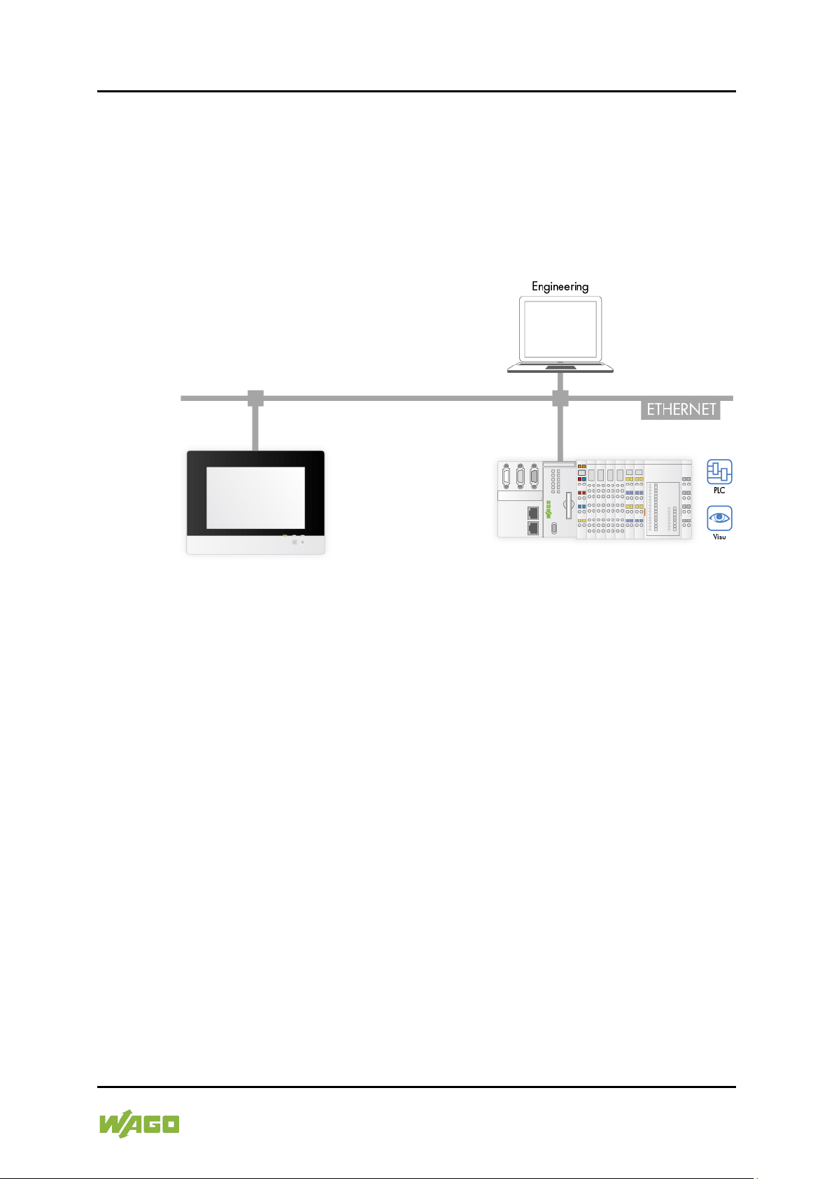
6.4 Connection Example
Figure 10: Connection Example
Manual
Version 1.1.0
Page 51

e!DISPLAY 7300T Commissioning 51
762-300X Web Panels
7 Commissioning
7.1 Removing the Protection Film
First remove the protection film from the touch screen. This film is not intended
for permanent use but only for mounting resp. connecting works.
7.2 Switching ON
The panel does not have an ON/OFF switch and is switched on together with
your machine resp. system.
At commissioning or if set, at each switching ON, following device startup you are
prompted to calibrate the screen. For this, touch the calibration points on the
screen shown successively. The calibration process is skipped if you remain
inactive for 20 seconds.
After booting the system, you are automatically taken to the WBM, PLC list or a
selected controller depending on the settings. You can interrupt the sequence
and arrive at a selection menu if you interrupt the countdown shown by touching
the screen.
7.3 Log-in
Before the WBM interface can be displayed, you are prompted to log in with a
user name and password. If starting the WBM for the first time, you have to use
the initial password. The password for “admin” is “wago”. Change the initial
password after logging in for the first time. See also section 4 “Function
Description” > “Network” and section 7 “Commissioning” > “Configuring in the
Web-Based Management (WBM)” > “WBM page ‘Administration>Users’”.
7.4 Using the Setup Wizard
At commissioning, a step-by-step wizard supports you during setup. In five steps,
you are prompted to make some basic settings to ensure the general operation of
your machine resp. system.
You can change any settings made later. To do so, launch the setup wizard
again from the function menu or go to individual settings via the WBM navigation
menu.
Manual
Version 1.1.0
Page 52

52 Commissioning e!DISPLAY 7300T
762-300X Web Panels
Step 1 – Touch Screen Calibration:
Choose to calibrate the touch screen at each switching on the panel or not.
Step 2 – IP Configuration:
Choose the network settings for the panel. For detailed information about these
settings, see also section “Commissioning” > “Configuring in the Web-Based
Management (WBM)” > “WBM Page ‘Networking>TCP/IP’”.
Manual
Version 1.1.0
Page 53

e!DISPLAY 7300T Commissioning 53
762-300X Web Panels
Step 3 – PLC List:
Add the controller used in the PLC list as required. For detailed information about
this setting, see also section “Commissioning” > “Configuring in the Web-Based
Management (WBM)” > “WBM Page ‘Application>PLC List’”.
Step 4 – Browser Security Level:
Select the browser security level (Low or High).
Any change only takes effect at the next power ON.
Manual
Version 1.1.0
Page 54

54 Commissioning e!DISPLAY 7300T
762-300X Web Panels
Step 5 – Start Page:
Choose to load the WBM, PLC list or a specific controller “PLC n” as the start
page when switching on the device.
Finish
Press the [Finish] button to end the setup wizard and to return to the WBM
interface.
Manual
Version 1.1.0
Page 55

e!DISPLAY 7300T Commissioning 55
762-300X Web Panels
7.5 Configuring in the Web-Based Management (WBM)
After switching on for the first time, the WBM user interface is displayed
automatically. If you want to change the configuration later during operation,
press the “CFG/RST” button or use the swipe gesture (see also section 8
“Running Web Visualization”).
In the WBM user interface, you configure the Web panel directly on the touch
screen.
Alternatively, you can also connect the Web panel to your PC via ETHERNET
and configure the Web panel from the PC. For this purpose, read the panel's IP
address in the WBM under “Information” > “Network Details X1/X2” and then
enter it as the address in the PC's Web browser.
7.5.1 WBM User Interface
The WBM user interface is divided into three areas:
1. Header
2. Navigation menu
3. Content area
Figure 11: WBM User Interface
Manual
Version 1.1.0
Page 56

56 Commissioning e!DISPLAY 7300T
762-300X Web Panels
Depending on the screen size, the navigation menu and content area may not be
displayed side by side, but each on the full screen. You can then switch between
the menu and content area.
7.5.1.1 Header (1)
In the header from left to right:
• Navigation path:
The path allows you to see immediately where you are in the WBM. If the
path does not fit in the available space entirely, the path is shorted using
“...”.
• Search function:
The search function is called up by pressing this button. You can go to the
respective settings by entering the menu entries directly.
• Logout:
Log the current user out if you do not want to use the interface any longer.
You then return to the logon prompt.
• Back:
This button only appears when displaying the full navigation menu or
content area. Use this button to navigate one level back in the navigation
path.
• Function menu:
Call up the function menu. The function menu provides quick access to
frequently used functions. See also section “Configuring in the Web-Based
Management (WBM)” > “WBM Function Menu”.
7.5.1.2 Navigation Menu (2)
The navigation menu (on the right side or full screen depending on the screen
size) allows you to access the device settings. The menu is structured in two
levels as a nested list. Menu entries have associated content that appears when
you select it or sub-items when selected. Menu items that contain sub-items are
indicated by an arrow.
If the menu cannot be displayed at full height, scrollbars will appear.
Manual
Version 1.1.0
Page 57

e!DISPLAY 7300T Commissioning 57
762-300X Web Panels
The top menu items are:
• Information
• Application
• Display
• Networking
• Firewall
• Ports and Services
• Administration
• Clock
7.5.1.3 Content Area (3)
You can view and change selected settings in the content area. In general,
settings are ordered in groups. Each group has its own window that can be
expanded and collapsed by pressing the title.
There may be various control elements for setting parameters in a group. When
enabled, each control element can be used by touching them. Depending on the
type of parameter, the control elements are:
• Input boxes: For entering text, numbers, IP addresses, etc.
• Drop-down lists: For selecting settings from a list of predefined options.
• [ON] and [OFF] buttons: For enabling/disabling parameters.
• Sliders: For setting a value to a defined scale.
• Buttons: For executing specific actions.
• [Submit] button: For confirming and applying any setting change.
Manual
Version 1.1.0
Page 58

58 Commissioning e!DISPLAY 7300T
762-300X Web Panels
2 Examples
Settings cannot always be changed. Under certain conditions, individual settings
may be disabled. If disabled, the setting is grayed out and cannot be operated.
E. g., [Submit] is only enabled if a respective setting has been changed.
The navigation menu is used to go to the following WBM pages:
Manual
Version 1.1.0
Page 59

e!DISPLAY 7300T Commissioning 59
Information
►Device Details
►Product Description
►Firmware Revision
►Network Details X1/X2
►State
►Subnet Mask
►Operating Hours
►Total
►Vendor Information
Table 23: WBM Page “Information” – “Device Details” Group
Parameters
Explanation
Product Description
Panel description
Order Number
Panel order number
Serial Number
Unique product serial number
Firmware Revision
Firmware status
Table 24: WBM Page “Information” – “Network Details Xn” Group
Parameters
Explanation
State of the X1 or X2 ETHERNET interface
MAC address used for panel identification and
addressing
IP Address
Current IP address of the panel
Subnet Mask
Current subnet mask of the panel
762-300X Web Panels
7.5.2 WBM Page “Information”
►Order Number
►Serial Number
►Mac Address
►IP Address
The following tables explain the parameters listed on this page:
7.5.2.1 “Device Details” Group
The panel properties are displayed in this group.
7.5.2.2 “Network Details X1/X2” Group
The network and interface properties are displayed in this group.
State
Mac Address
(enabled/disabled)
7.5.2.3 “Operating Hours” Group
The panel's total hours of operation are indicated in this group.
7.5.2.4 “Vendor Information” Group
The manufacturer and address are in this group.
Manual
Version 1.1.0
Page 60

60 Commissioning e!DISPLAY 7300T
Application
►PLC List
►PLC n
►Text
Table 25: WBM Page “Application > PLC List ” – “PLC n” Groups
Parameters
Explanation
Text
Enter any name for the controller.
Enter the URL at which the controller's Web
visualization is reached.
Determine if the virtual panel keyboard is to be used
762-300X Web Panels
7.5.3 WBM Page “Application > PLC List”
►URL
►Virtual Keyboard
►WebVisu
This page maintains a list of adjustable controllers for you.
7.5.3.1 “PLC n” Groups
Each group describes the connection to a specific controller. If the name of a
controller is changed, it also becomes the new group label.
URL
Virtual Keyboard
WebVisu Determine if the specified URL is a WebVisu or not.
Click on [Submit] to apply the changes. To reset all settings click on [Reset] and
on [Submit] to confirm the reset.
when displaying the URL of this controller. This is
useful, e.g., if you want to display a WebVisu that
requires its own virtual keyboard.
7.5.4 WBM Page “Application > Startpage”
Application ►Startpage ►Startpage
You can set the panel's start page on this page.
7.5.4.1 “Startpage” Group
Select the start page to be displayed when switching on the panel.
Manual
Version 1.1.0
Page 61

e!DISPLAY 7300T Commissioning 61
Application
►Autostart
►Autostart Delay
►Delay (sec.)
Application
►Monitoring
►Monitoring
►Reconnect
Table 26: WBM Page “Application > Monitoring” – “Monitoring” Group
Parameters
Explanation
Determine if an attempt is made automatically to
Application
►Browser Security
►Browser Security
►Browser Security
762-300X Web Panels
7.5.5 WBM Page “Application > Autostart”
You can set the Autostart options for the panel on this page.
7.5.5.1 “Autostart Delay” Group
Set the countdown displayed when booting before displaying the start page.
Within the time set, you have the option to prevent the panel from switching to
the start page and to go to the WBM directly.
A delay of “0” displays the start page immediately.
7.5.6 WBM Page “Application > Monitoring”
►Interval (sec.)
Make settings here for monitoring the panel.
7.5.6.1 “Monitoring” Group
Reconnect
Interval (sec.) Specify an interval for the attempts.
restore a connection if the connection to the
controller is interrupted.
7.5.7 WBM Page “Application > Browser Security”
Determine the browser security level on the panel.
7.5.7.1 “Browser Security” Group
Select the required security level (Low or High).
Manual
Version 1.1.0
Page 62

62 Commissioning e!DISPLAY 7300T
Table 27: WBM Page “Application > Browser Security” – “Browser Security” Group
Parameters
Explanation
• Low: In this security level, HTTPS connections are
permitted in “Low” that are listed above are rejected.
762-300X Web Panels
permitted with:
•• Certificates that are not yet valid
Browser Security
•• Certificates that have expired
•• Certificates that are self-signed
•• Certificates with host names that do not match
• High: In this security level, the connections
Manual
Version 1.1.0
Page 63

e!DISPLAY 7300T Commissioning 63
Display
►Touchscreen Calibration
►Touchscreen Calibration
►Calibrate
Display
Display
►Acoustic Signal
►Acoustic Touch Signal
►Acoustic Signal
Display
►Brightness
►Brightness
►Brightness
►Brightness Screensaver
►Brightness Screensaver
►Brightness Control
►Day / Night Settings
saver
762-300X Web Panels
7.5.8 WBM Page “Display > Touchscreen Calibration”
This page shows settings options for the display calibration.
7.5.8.1 “Touchscreen Calibration” Group
Determine if the display should be calibrated or not when switching on the panel.
7.5.9 WBM Page “Display > Acoustic Signal”
You can enable panel beeps on this page.
7.5.9.1 “Acoustic Touch Signal” Group
Determine if an acoustic signal (beep) is output or not when touching the display.
If yes, the beep is emitted when the display is touched. However, no check is
made whether a button was also touched.
7.5.10 WBM Page “Display > Brightness”
You can adjust the settings for display brightness on this page.
7.5.10.1 “Brightness” Group
►Starting Time Day
►Starting Time Night
►Brightness Night
►Brightness Night Screen-
7.5.10.2 “Brightness Screensaver” Group
Manual
Version 1.1.0
Use the slider to adjust the default display brightness. You can test the
brightness before confirming the setting. Press [Test].
Use the slider to adjust the reduced brightness for the screensaver. You can test
the brightness before confirming the setting. Press [Test].
Page 64

64 Commissioning e!DISPLAY 7300T
Table 28: WBM Page “Display > Brightness” – “Brightness Control” Group
Parameters
Explanation
Select a control method or disable the brightness
• Sensor
Specify at what time the default brightness is
Specify at what time the night brightness is
activated.
Brightness Night
Specify the reduced night brightness value for the
Display
►Screensaver
►Screensaver Settings
►Screensaver Settings
762-300X Web Panels
7.5.10.3 “Brightness Control” Group
A sensor that measures the ambient brightness or the time of day can be used to
automatically switch the display brightness to night values if required.
Set the switching times and night values.
control.
• No brightness control: disabled
Day / Night Settings
• Day/Night: The brightness adjustment for day and
night operation is made according to the following
four parameters.
Starting Time Day
Starting Time Night
Brightness Night Specify the night brightness value.
Screensaver
activated.
night screensaver.
7.5.11 WBM Page “Display > Screensaver”
You can adjust the screensaver on this page.
7.5.11.1 “Screensaver Settings” Group
Determine if and how a screensaver should be used.
►Duration (sec.)
►Text
►Time (hh:mm:ss)
Manual
Version 1.1.0
Page 65

e!DISPLAY 7300T Commissioning 65
Table 29: WBM Page “Display > Screensaver” – “Screensaver Settings” Group
Parameters
Explanation
Specify if an image, the time, text or a backlight
• Off: No screensaver is displayed.
When the display is not used, the screensaver is
activated after the time set here has elapsed.
Enter any text display as the text screensaver.
(Can be adjusted in the “Text” option.)
Enter the time at which screen care should be
Display
►Clean Display
►Clean Display
►Time Duration (sec.)
Display
►Display Orientation
►Display Orientation
►Display Orientation
762-300X Web Panels
should be displayed or if screen care should be
performed.
• Image: The screensaver is activated with the
WAGO logo after a time set under “Duration”.
• Text: Enter text here that is activated as the
screensaver after a time set under “Duration”.
• Time: The current time is displayed as the
Screensaver Settings
screensaver.
• Backlight: The brightness is reduced to the
screensaver brightness and the WAGO logo
displayed. Set the required brightness reduction
under “Display > Brightness > Brightness
Screensaver”.
• Screen care: For screen care, all pixels are
inverted for a few milliseconds (not visible).
Duration (sec.)
Text
Time (hh:mm:ss)
7.5.12 WBM Page “Display > Clean Display”
You can adjust the settings for display cleaning on this page.
7.5.12.1 “Clean Display” Group
Set how long the display should be disabled for cleaning.
7.5.13 WBM Page “Display > Display Orientation”
performed.
(Can be adjusted in the “Screen care” option.)
You can adjust the settings for display orientation on this page.
7.5.13.1 “Display Orientation” Group
Set if the display should appear in portrait or landscape mode. The options are
landscape, portrait, landscape rotated and portrait rotated.
Manual
Version 1.1.0
Page 66

66 Commissioning e!DISPLAY 7300T
Networking
►Host/Domain Name
►Hostname
►Currently used
►Configured
►Domain Name
►Currently used
►Configured
Table 30: WBM Page “Networking > Host/Domain Name” – “Hostname” Group
Parameters
Explanation
If you have selected dynamic assignment of an IP
being used is displayed.
Enter the hostname of your panel that is then used if
response.
Table 31: WBM Page “Networking > Host/Domain Name” – “Domain Name” Group
Parameters
Explanation
If you have selected dynamic assignment of an IP
currently being used is displayed.
Configured
Set the domain name here.
762-300X Web Panels
7.5.14 WBM Page “Networking > Host/Domain Name”
The settings for general TCP/IP parameters are located on the “Networking >
Host/Domain Name” page.
7.5.14.1 "Hostname" Group
Currently used
Configured
Click on [Submit] to apply a change. It is effective immediately.
If a host name is supplied via a DHCP response, this is active in the system. If
there are several network interfaces with DHCP always the last received host
name is valid.
If only the host name configured here is to be valid, the configuration of the
DHCP server must be adapted so that no host names are transferred in the DHCP
response.
7.5.14.2 “Domain Name” Group
Currently used
address via DHCP, the name of the host currently
the network interface is changed to a static IP
address or if no hostname is assigned per DHCP
address via DHCP, the name of the domain
Click on [Submit] to apply a change. It is effective immediately.
If a domain name is supplied via a DHCP response, this is active in the system. If
there are several server network interfaces with DHCP, always the last received
domain name is valid.
If only the domain name configured here is to be valid, the configuration of the
DHCP server must be adapted so that no domain names are transferred in the
DHCP response.
Manual
Version 1.1.0
Page 67

e!DISPLAY 7300T Commissioning 67
Networking
►TCP/IP
►IP Configuration
►Configuration Type
►Subnet Mask
►Default Gateway n
►Gateway enabled
►DNS Server
►Configured: None/
Table 32: WBM Page “Networking > TCP/IP” – “IP Configuration” Group
Parameters
Explanation
Select a static or dynamic IP address.
Static IP
Static IP addressing
DHCP
Dynamic IP addressing
BootP
Dynamic IP addressing
Enter here a static IP address. This is active if
Enter the subnet mask here. This is active if “Static
IP” is activated in the Configuration Type field.
762-300X Web Panels
7.5.15 WBM Page “Networking > TCP/IP”
►IP Address
►Gateway Address
►Gateway Metric
DNS Server n
►New Server IP
►Additionally used
(assigned by DHCP)
The TCP/IP settings for the ETHERNET interfaces are located on the
“Networking > TCP/IP” page.
7.5.15.1 “IP Configuration” Group
Configuration Type
IP Address
“Static IP” is activated in the Configuration Type
field.
Subnet Mask
Click on [Submit] to apply a change. It is effective immediately.
7.5.15.2 “Default Gateway n” Groups
You can configure two default gateways here. The panel sends all network data
that does not go to a subscriber in the local network to a default gateway. First,
the gateway with the lowest metric is addressed. If it is accessible, the second
gateway is used. The selection is random if the metric is the same.
A default gateway can also be configured via DHCP. These default gateways are
given the metric 10, by which they are normally used before the static gateways.
Manual
Version 1.1.0
Page 68

68 Commissioning e!DISPLAY 7300T
Table 33: WBM Page “Networking > TCP/IP” – “Default Gateway n” Group
Parameters
Explanation
Set here whether the selected default gateway is to
Disabled
The default gateway is not used.
Enabled
The default gateway is used.
Gateway Address
Enter the address of the default gateway here.
Set here a number as the metric. With multiple
The highest value is 4.294.967.295.
Table 34: WBM Page “Networking > TCP/IP” – “DNS Server” Group
Parameters
Explanation
The addresses of the defined DNS servers are
displayed.
New Server IP
Add additional DNS addresses here.
Networking
►Ethernet
►Interface X1
►Enabled
►Speed / Duplex
►Interface X2
►Enabled
►Switch Configuration
►Port Mirror
►Rate Limit
762-300X Web Panels
Gateway enabled
Gateway Metric
Click on [Submit] to apply a change. It is effective immediately.
7.5.15.3 "DNS Server" Group
DNS Server n
be used.
default gateways, the metric defines the gateway to
which data packets are first sent. Priority is given to
the gateway with the lower metric. The default value
for the metric is 20.
The lowest value is 0.
displayed here. If not server is entered, none is
Click on [Delete] to remove the selected DNS server. The change is effective
immediately.
Click on [Submit] to add the entered DNS server. The change is effective
immediately.
7.5.16 WBM Page “Networking > Ethernet”
►Autonegotiation On
►Autonegotiation On
►Speed / Duplex
►Fast Aging Enabled
►Broadcast Protection
Manual
Version 1.1.0
The ETHERNET settings are located on the “Networking > Ethernet” page.
Page 69

e!DISPLAY 7300T Commissioning 69
Table 35: WBM Page “Networking > Ethernet” – “Interface X1” and “Interface X2” Groups
Parameters
Explanation
Enabled
You can enable or disable the interface.
When Autonegotiation is enabled, the connection
modalities are negotiated automatically with the peer
devices.
Information can be sent
762-300X Web Panels
7.5.16.1 “Interface X1” and “Interface X2” Groups
Autonegotiation On
Select the transmission speed and the duplex
method:
Speed / Duplex
10 Mbit half-duplex
100 Mbit half-duplex
Information can only be
sent or received.
10 Mbit full-duplex
and received
100 Mbit full-duplex
simultaneously.
Click on [Submit] to apply a change. It is effective immediately.
Manual
Version 1.1.0
Page 70

70 Commissioning e!DISPLAY 7300T
Table 36: WBM Page “Networking > Ethernet” – “Switch Configuration” Group
Parameters
Explanation
Enable or disable the mirroring of the data traffic
Both ETHERNET ports are operating
normally.
All data traffic between X1 and the
Web panel is mirrored on X2.
All data traffic between X2 and the
The aging limit of unused entries is set in the list of
network devices.
An unused address entry becomes
obsolete after 200 seconds.
An unused address entry becomes
obsolete after 800 microseconds.
Set here the broadcast limit for protection against
Disabled
No broadcast packet limit
Limiting incoming broadcast packets to
possible data throughput (10/100Mbit)
Set here the basic limitation of the incoming data
traffic.
Disabled
No limitation of the incoming data traffic
64 kbps …
99 mbps
Limitation of the incoming data traffic to
the entered value
762-300X Web Panels
7.5.16.2 “Switch Configuration” Group
between the ports.
None
Port Mirror
X1
Fast Aging Enabled
Broadcast Protection
Rate Limit
Click on [Submit] to apply a change. It is effective immediately.
X2
Web panel is mirrored on X1.
MAC addresses with port mapping to external
Disabled
Enabled
overloads.
1% … 5%
the selected percentage of the total
Manual
Version 1.1.0
Page 71

e!DISPLAY 7300T Commissioning 71
Firewall
►General Configuration
►Global Firewall
►Firewall enabled
►Firewall
►Firewall Enabled
►Firewall
►Telnet
►SSH
Table 37: WBM Page “Firewall > General Configuration” – “Global Firewall Parameters” Group
Parameters
Explanation
Enables/disables the complete functionality of the
firewall.
ICMP Echo Broadcast
Protection
Enable or disable the “ICMP Echo Broadcast”
protection.
Max. UDP Connections per
You can specify the maximum number of UDP
Max. TCP Connections per
second
You can specify the maximum number of TCP
connections per second.
762-300X Web Panels
7.5.17 WBM Page “Firewall > General Configuration”
Parameters
►ICMP Echo Broadcast
Protection
►Max. UDP Connections
per second
►Max. TCP Connections
per second
Parameter
Interface
X1/X2
Services
Interface
X1/X2
►ICMP Echo Protection
►ICMP Echo Burst Limit
per Second
►FTP
►FTPS
►HTTP
►HTTPS
7.5.17.1 “Global Firewall Parameters” Group
firewall. This setting has the highest priority. If the
firewall is disabled, all other settings have no direct
Firewall enabled
second
Click on [Submit] to apply a change. It is effective immediately.
effect. The configuration of the other parameters is
possible nevertheless so that you can set the
firewall parameters correctly before you enable the
connections per second.
Manual
Version 1.1.0
Page 72

72 Commissioning e!DISPLAY 7300T
Table 38: WBM Page “Firewall > General Configuration” – “Firewall Parameter Interface X1/X2”
Group
Parameters
Explanation
Enable or disable the firewall for the relevant
interface.
Enable or disable the “ICMP echo broadcast”
ICMP Echo Burst Limit per
second
You can specify the maximum number of “ICMP
echo bursts” per second.
Table 39: WBM Page “Firewall > General Configuration” – “Firewall Services Interface X1/X2”
Group
Parameters
Explanation
Telnet
FTP
FTPS
HTTP
HTTPS
SSH
762-300X Web Panels
7.5.17.2 “Firewall Parameter Interface X1/X2” Group
The settings in this group are based on the firewall configuration on the IP level.
Firewall Enabled
ICMP Echo Protection
protection for the relevant interface.
Click on [Submit] to apply a change. It is effective immediately.
7.5.17.3 “Firewall Services Interface X1/X2” Group
The settings in this group are based on the firewall configuration on the IP level.
Enable or disable the firewall for the respective
service.
The services themselves must be enabled or
disabled separately on the “Ports and Services”
page.
Click on [Submit] to apply a change. It is effective immediately.
Manual
Version 1.1.0
Page 73

e!DISPLAY 7300T Commissioning 73
Firewall
►MAC
Filter
►MAC Address Filter State
►Current State
►MAC Address Filter State X1/X2
►Current State
►MAC Address Filter Whitelist
►Filter Enabled
►Add New MAC Address Filter
►Filter Enabled
762-300X Web Panels
7.5.18 WBM Page “Firewall > MAC Address Filter”
Address
►MAC Address
►MAC Mask
►MAC Address
►MAC Mask
You set the firewall configuration at ETHERNET level on this page.
The “MAC address filter whitelist” contains a default entry with the following
values:
MAC address: 00:30:DE:00:00:00
MAC mask: ff:ff:ff:00:00:00
If you activate the default entry, different WAGO devices in your network can
communicate with each other.
Enable the MAC address before filter activation!
Before you enable the MAC Address Filter, you have to enter and activate your
own MAC address in the “MAC Address Filter Whitelist”.
Otherwise you cannot access the device via the ETHERNET. This also applies to
other services that are used by your device, e.g., the IP configuration via DHCP.
If the “MAC Address Filter Whitelist” does not contain the MAC address of your
DHCP server, your device will lose its IP settings after the next refresh cycle and
is then no longer accessible.
If the “MAC Address Filter Whitelist” does not contain an entry, the activation of
the filter is prevented.
If at least one activated address is entered, you will receive an appropriate
warning before activation, which you have to acknowledge.
Manual
Version 1.1.0
Page 74

74 Commissioning e!DISPLAY 7300T
Table 40: WBM Page “Firewall > MAC Address Filter” – “MAC Address Filter State” Group
Parameters
Explanation
Enable or disable the global MAC address filter
Table 41: WBM Page “Firewall > MAC Address Filter” – “MAC Address Filter State X1/X2” Group
Parameters
Explanation
Enable or disable here the MAC address filter for the
specific interface.
Table 42: WBM Page “Firewall > MAC Address Filter” – “MAC Address Filter Whitelist” Group
Parameters
Explanation
Enable or disable the filter for the relevant list entry
here.
MAC Address
Displays the MAC address of the relevant list entry.
MAC Mask
Displays the MAC mask of the relevant list entry.
Table 43: WBM Page “Firewall > MAC Address Filter” – “Add New MAC Address Filter” Group
Parameters
Explanation
Enable or disable the filter for the new list entry
here.
Enter here the MAC address for a new list entry.
You can enter 10 filters.
Enter the MAC mask for the new list entry here. You
762-300X Web Panels
7.5.18.1 “MAC Address Filter State” Group
Current State
here.
Click on [Submit] to apply a change. It is effective immediately.
7.5.18.2 “MAC Address Filter State X1/X2” Group
Current State
Click on [Submit] to apply a change. It is effective immediately.
7.5.18.3 “MAC Address Filter Whitelist” Group
Filter Enabled
Click on [Submit] to apply a change. It is effective immediately.
Click on the appropriate [Delete] button to remove an existing list entry. The
change is effective immediately.
7.5.18.4 “Add New MAC Address Filter” Group
Add a new entry to the whitelist from this form.
Filter Enabled
MAC Address
MAC Mask
Click on [Submit] to apply the new list entry. The change is effective
immediately. You can enter 10 filters.
can enter 10 filters.
Manual
Version 1.1.0
Page 75

e!DISPLAY 7300T Commissioning 75
Firewall
►User Filter
►User Filter Count
►Count
►User Filter n
►Source IP Address
►Input Interface
►Add New User
►Source IP Address
►Input Interface
Table 44: WBM Page “Firewall > User Filter” – “User Filter Count” Group
Parameters
Explanation
The number of configured user filters is displayed
here.
762-300X Web Panels
7.5.19 WBM Page “Firewall > User Filter”
►Source Netmask
►Source Port
►Destination IP Address
►Destination Subnet Mask
►Destination Port
►Protocol
Filter
7.5.19.1 “User Filter Count” Group
Count
►Source Netmask
►Source Port
►Destination IP Address
►Destination Subnet Mask
►Destination Port
►Protocol
Manual
Version 1.1.0
Page 76

76 Commissioning e!DISPLAY 7300T
Table 45: WBM Page “Firewall > User Filter” – “User Filter n” Group
Parameters
Explanation
Displays the source IP address used for the
This displays the source network for the
corresponding filter entry.
This displays the source port number for the
corresponding filter entry.
Displays the destination IP address currently used
Displays the destination network mask for the
currently used filter entry.
Displays the destination port number for the
currently used filter entry.
Displays the permitted protocols for the currently
used filter.
Displays the permitted interfaces for the respective
762-300X Web Panels
7.5.19.2 “User Filter n” Group
Source IP Address
corresponding filter entry.
Source Netmask
Source Port
Destination IP Address
for the filter entry.
Destination Subnet Mask
Destination Port
Protocol
Input Interface
filter.
Click on the appropriate [Delete] button to remove a configured filter. The
change is effective immediately.
7.5.19.3 “Add New User Filter” Group
You only have to enter values in the fields that are to be set for the filter. At least
one value must be entered; all other fields can remain empty.
Manual
Version 1.1.0
Page 77

e!DISPLAY 7300T Commissioning 77
Table 46: WBM Page “Firewall > User Filter” – “Add New User Filter” Group
Parameters
Explanation
Enter here the source IP address for the new filter
Enter here the source network mask for the new
filter entry.
Enter here the source port number for the new filter
entry.
Enter here the destination IP address for the new
filter entry.
Enter here the destination network mask for the new
Enter here the destination port number for the new
filter entry.
Enter here the permitted protocols for the new filter.
TCP
The TCP service is permitted.
UDP
The UDP service is permitted.
Enter here the permitted interfaces for the new filter.
X1
The interface X1 is permitted.
X2
The X2 interface is permitted.
VPN
The VPN interface is permitted.
762-300X Web Panels
Source IP Address
entry.
Source Netmask
Source Port
Destination IP Address
Destination Subnet Mask
filter entry.
Destination Port
Protocol
Input Interface
Click on [Submit] to apply a change. It is effective immediately.
Manual
Version 1.1.0
Page 78

78 Commissioning e!DISPLAY 7300T
Ports and
Services
►Network Services
►TELNET
►TELNET
►FTP
►FTP
►FTPS
►FTPS
►HTTP
►HTTP
►HTTPS
►HTTPS
Table 47: WBM Page “Ports and Services > Network Services” – “Telnet” Group
Parameters
Explanation
TELNET
Enable/disable the Telnet service here.
Table 48: WBM Page “Ports and Services > Network Services” – “FTP” Group
Parameters
Explanation
FTP
Enable/disable the FTP service here.
Table 49: WBM Page “Ports and Services > Network Services” – “FTPS” Group
Parameters
Explanation
FTPS
Enable/disable the FTPS service here.
Table 50: WBM Page “Ports and Services > Network Services” – “HTTP” Group
Parameters
Explanation
HTTP
Enable/disable the HTTP service here.
762-300X Web Panels
7.5.20 WBM Page “Ports and Services > Network Services”
The settings for the different services are located on the “Ports and Services”
page.
In addition to enabling/disabling the individual services on this page, you can limit
the services for each individual interface via the firewall on the “Firewall >
General Configuration” page.
7.5.20.1 “TELNET” Group
Click on [Submit] to apply a change. It is effective immediately.
7.5.20.2 "FTP" Group
Click on [Submit] to apply a change. It is effective immediately.
7.5.20.3 "FTPS" Group
Click on [Submit] to apply a change. It is effective immediately.
7.5.20.4 "HTTP" Group
Click on [Submit] to apply a change. It is effective immediately.
Manual
Version 1.1.0
Page 79

e!DISPLAY 7300T Commissioning 79
Table 51: WBM Page “Ports and Services > Network Services” – “HTTPS” Group
Parameters
Explanation
HTTPS
Enable/disable the HTTPS service here.
Ports and
►SSH
►SSH Server State
►SSH Server State
►SSH Server Parameter
►Port Number
Table 52: WBM Page “Ports and Services > SSH” – “SSH Server State” Group
Parameters
Explanation
SSH Server State
Enable/disable the SSH server here.
Table 53: WBM Page “Ports and Services > SSH” – “SSH Server Parameter” Group
Parameters
Explanation
Port Number
Enter the port number here.
Allow root login
Enable/disable root access here.
Allow password login
Enable/disable the password query function here.
762-300X Web Panels
Connection abort on disabling
If the HTTP service is disabled, the connection to the panel can be aborted. Then
call up the WBM page again.
7.5.20.5 “HTTPS” Group
Click on [Submit] to apply a change. It is effective immediately.
Connection abort on disabling
If the HTTP service is disabled, the connection to the panel can be aborted. Then
call up the WBM page again.
7.5.21 WBM Page “Ports and Services > SSH”
Services
The SSH service settings are located on the “SSH” page.
7.5.21.1 “SSH Server State” Group
Click on [Submit] to apply a change. It is effective immediately.
7.5.21.2 “SSH Server Parameter” Group
►Allow root login
►Allow password login
Manual
Version 1.1.0
Page 80

80 Commissioning e!DISPLAY 7300T
Administration
►Users
►Change Password for
►Select User
Table 54: WBM Page “Administration > Users” – “Change Password for selected user” Group
Parameters
Explanation
Select the user (“user” or “admin”) to whom you
want to assign a new password.
Enter the new password for the user selected under
! ? % + = ( ) _ # " - / ` < > * ; , : .
Confirm Password
Enter the new password again for confirmation.
762-300X Web Panels
Click on [Submit] to apply a change. It is effective immediately.
7.5.22 WBM Page “Administration > Users”
Selected WBM User
►New Password
►Confirm Password
The settings for user administration are shown on this page.
7.5.22.1 “Change Password for Selected WBM User” Group
Change passwords!
The initial passwords as delivered are documented in this manual and therefore
do not provide sufficient protection. Change the passwords to meet your
particular needs!
Select User
“Select User”.
New Password
Permitted characters for the password are the
following ASCII characters: a … z, A … Z, 0 … 9,
blank spaces and the special characters:
Click on [Submit] to apply a change. It is effective immediately.
Only use permitted characters for WBM passwords!
If passwords with invalid characters are set for the WBM outside the WBM (e.g.,
from a USB keyboard), access to the WBM pages directly on the display is no
longer possible because only permitted characters are available from the virtual
keyboard.
Observe access rights!
The users in WBM exclusively have access to the Web pages. User
administration for controller applications is configured separately.
Manual
Version 1.1.0
Page 81

e!DISPLAY 7300T Commissioning 81
Clock
►Date on Device
►Local
►Time on Device
►Local
►Timezone
►Timezone
►TZ String
►TZ String
Table 55: WBM Page “Clock” – “Date on Device” Group
Parameters
Explanation
Local
Enter the date here.
Table 56: WBM Page “Clock” – “Time on Device” Group
Parameters
Explanation
Local
Enter the local time here.
UTC
Enter the GMT time here.
Clock Format
For setting 12-hour or 24-hour time display.
762-300X Web Panels
7.5.23 WBM Page “Clock”
►UTC
►Clock Format
The date and time settings are given on the "Clock" page.
7.5.23.1 "Date on Device" Group
Click on [Submit] to apply a change. It is effective immediately.
7.5.23.2 "Time on Device" Group
Click on [Submit] to apply a change. It is effective immediately.
Manual
Version 1.1.0
Page 82

82 Commissioning e!DISPLAY 7300T
Table 57: WBM Page “Clock” – “Timezone” Group
Parameters
Explanation
Specify the appropriate time zone for your location
“Eastern Standard Time”, New York,
Toronto
“Central Standard Time”, Chicago,
Winnipeg
“Mountain Standard Time”, Denver,
Edmonton
“Pacific Standard Time”, Los Angeles,
“Greenwich Mean Time”, GB, P, IRL,
IS, …
“Central European Time”, B, DK, D,
F, I, CRO, NL, …
“East European Time”, BUL, FI, GR,
TR, …
CST
“China Standard Time”
JST
“Japan/Korea Standard Time”
Table 58: WBM Page “Clock” – “TZ String” Group
Parameters
Explanation
For time zones that cannot be selected from the
http://www.timeanddate.com/time/map/
762-300X Web Panels
7.5.23.3 “Timezone” Group
here. Default setting:
AST/ADT “Atlantic Standard Time”, Halifax
EST/EDT
CST/CDT
MST/MDT
Timezone
Click on [Submit] to apply a change. It is effective immediately.
7.5.23.4 "TZ String" Group
TZ String
PST/PDT
Whitehouse
GMT/BST
CET/CEST
EET/EEST
“Time Zone” parameter, enter the name of the time
zone or the country or city applicable to you.
You can define a valid name for the time zone here:
Click on [Submit] to apply a change. It is effective immediately.
Manual
Version 1.1.0
Page 83

e!DISPLAY 7300T Commissioning 83
762-300X Web Panels
7.5.24 WBM Function Menu
The function menu provides quick access to frequently used functions. The
functions are described below.
7.5.24.1 Reboot
Reboot restarts the panel.
7.5.24.2 PLC Selection List
PLC Selection List exits the WBM and takes you to the “PLC Selection List”
from where you can start a Web visualization.
7.5.24.3 Start Clean Display
The Start Clean Display menu item starts the function described in section
“Performing Service” > “Cleaning the Touch Screen”.
7.5.24.4 Start Screensaver
The Start Screensaver function can be used to manual start the screensaver.
This function is only available on the local WBM.
7.5.24.5 Font Upload
From the Font Upload menu item, you can install True Type fonts on the panel.
In addition, True Type fonts manually installed by the user are displayed. See
also section “Function Description” > “Font Upload”.
7.5.24.6 Backup
The Backup menu item allows you to create a backup as described in “Function
Description > Memory Card Functions > Backup”. If called up in the local WBM,
only the removable storage device can be used as the destination medium.
7.5.24.7 Restore
The Restore menu item allows you to install a backup as described in “Function
Description > Memory Card Functions > Restore”. If called up in the local WBM,
only the removable storage device can be used as the source medium.
7.5.24.8 Create Image
The Create Image menu item allows you to copy a complete system from or to
the SD card.
7.5.24.9 Diagnostic
The Diagnostic menu item displays the diagnostic messages. By selecting “All
notifications”, you are displaying all notifications and by selecting “Read only the
Manual
Version 1.1.0
Page 84

84 Commissioning e!DISPLAY 7300T
Parameter
Explanation
Software File
This shows the file name of the
“No upload file exists” is displayed.
Action
Select here the action required.
Activate
The transferred software package is
activated.
Discard (delete upload)
The transferred software package is
deleted again from the controller.
762-300X Web Panels
last ...”, you are displaying the last n diagnostic notifications. You can also specify
the number “n”.
“Automatic refresh cycle (sec)” switches on cyclic refresh. The refresh cycle
continues as long as the “Diagnostic” page is open. If you exit the “Diagnostic”
function, the refresh stops until you call up the “Diagnostic” menu item again.
The notifications are displayed below the settings.
7.5.24.10 Setup Wizard
The setup wizard can be manually launched from the Setup Wizard menu item.
7.5.24.11 Software Upload
From the Software Upload menu item, you can install software packages on the
panel from your PC. Using the Browse button, simply navigate to the software
package on your PC and click [Submit] to confirm.
Another “Activate new Software” form then appears. You can now choose
between the “Activate” and “Discard” actions, see also table below. Press
[Submit] to confirm.
The file with the software package is deleted again after the installation is
completed or when the controller is restarted.
transferred software package. If no
new uploaded software package is
present on the controller, the message
Manual
Version 1.1.0
Page 85

e!DISPLAY 7300T Commissioning 85
Table 59: WBM Factory Settings for Application
Parameter
Group
Parameter
Factory Setting
(Default Value)
Comment
PLC n
Text
-
No value specified as delivered.
URL
-
No value specified as delivered.
Virtual
ON
WebVisu
ON
Startpage
Startpage
Web-based Management
Autostart Delay
Delay (sec.)
3
Monitoring
Reconnect
ON
Reconnect interval in the event of
controller
Interval (sec.)
10
Browser Security
Browser
High
Options: Low, High
762-300X Web Panels
7.5.25 WBM Factory Settings
The tables below contain the factory settings for all WBM parameters:
Keyboard
connection interruptions to the
Security
Manual
Version 1.1.0
Page 86

86 Commissioning e!DISPLAY 7300T
Table 60: WBM Factory Settings for Display
Parameter
Group
Parameter
Factory Setting
(Default Value)
Comment
Touchscreen
Calibrate
ON
Calibration of the touch screen for
Acoustic Touch
Acoustic Signal
OFF
Beep when touching the touch
Brightness
Brightness
255 (max. brightness)
Default brightness
Brightness
Brightness
0 (min. brightness)
Reduced brightness for screensaver
Brightness Control
Day/Night
No Brightness Control
Options:
Starting Time
Day
-N/A-
Starting Time
Night
-N/A-
Brightness
Night
-N/A-
Brightness
Screensaver
-N/A-
Screensaver
Screensaver
Image
Options:
Duration (sec.)
600 [s]
Once the time has elapsed, the
Text
Screensaver example
Enter your free text here.
Time
(03:00:00)
Time at which screen care should
Clean Display
Time Duration
15 [s]
Countdown in seconds
Display Orientation
Display
Landscape
Options: Landscape, Landscape
762-300X Web Panels
Calibration
Signal
Screensaver
Settings
Display
Screensaver
Settings
Night
Settings
each device startup
screen
mode
No Brightness Control,
Day/Night, Sensor
Image, Text, Time, Backlight,
Screen care, Off
display switches to the screensaver
state.
text
(hh:mm:ss)
(sec.)
Orientation
be performed.
(remaining time for cleaning without
the display registering a touch)
rotated, Portrait, Portrait rotated
Manual
Version 1.1.0
Page 87

e!DISPLAY 7300T Commissioning 87
Table 61: WBM Factory Settings for Networking
Parameter
Group
Parameter
Factory Setting
(Default Value)
Comment
Host/Domain
Hostname,
e!DISPLAY number
“number” is the last 3 bytes of the
Domain Name,
-
No value specified as delivered.
IP Configuration
Configuration
DHCP
Options: Static IP, DHCP, BootP
IP Address
192.168.1.17
Subnet Mask
255.255.255.0
Default Gateway 1
Gateway
Enabled
OFF
Gateway
Address
192.168.1.1
Gateway Metric
20
Default Gateway 2
Gateway
Enabled
OFF
Gateway
Address
192.268.2.1
Gateway Metric
OFF
DNS server
New Server IP
-
No DNS server specified as
delivered.
Interface X1/X2
Enabled
Interface X1
Autonegotiation
ON Speed/Duplex
100M/full
Switch
Port Mirror
None
Fast Aging
Disabled
Broadcast
Protection
1
Rate Limit
Disabled
762-300X Web Panels
Name
Currently used
Currently used
Type
MAC address.
Configuration
Enabled
Manual
Version 1.1.0
Page 88

88 Commissioning e!DISPLAY 7300T
Table 62: WBM Factory Settings for Firewall
Parameter
Group
Parameter
Factory Setting
(Default Value)
Comment
Global Firewall
Firewall
Enabled
OFF
ICMP Echo
Protection
OFF
Max. UDP
-
No value specified as delivered.
Max. TCP
per Second
-
No value specified as delivered.
Firewall Parameter
Firewall
Enabled
OFF
ICMP Echo
Protection
OFF
ICMP Echo
Second
2
Firewall
Telnet
ON FTP
ON FTPS
ON HTTP
ON HTTPS
ON
SSH
ON
MAC Address
Filter State
Current State
ON MAC Address
Filter State X1/X2
Current State
OFF
MAC Address
Filter Enabled
OFF
MAC Address
00:30:DE:00:00:00
MAC Mask
ff:ff:ff:00:00:00
User Filter Count
Count
0
762-300X Web Panels
Parameters
Broadcast
Connections
per Second
Connections
Interface X1/X2
Burst Limit per
Services
Interface
X1/X2
Filter Whitelist
Manual
Version 1.1.0
Page 89

e!DISPLAY 7300T Commissioning 89
Table 63: WBM Factory Settings for Ports and Services
Parameter
Group
Parameter
Factory Setting
(Default Value)
Comment
TELNET
TELNET
OFF
FTP
FTP
OFF
FTPS
FTPS
ON
HTTP
HTTP
ON HTTPS
HTTPS
ON
SSH Server State
SSH Server
ON
SSH Server
Port Number
22
Allow Root
ON Allow Password
ON
Table 64: WBM Factory Settings for Administration
Parameter
Group
Parameter
Factory Setting
(Default Value)
Comment
Passwords
User Password
user
Admin
wago
Table 65: WBM Factory Settings for Clock
Parameter
Group
Parameter
Factory Setting
(Default Value)
Comment
Time on Device
Clock Format
24-hour format
Time viewer; can be switched to
Time zone
Time zone
CET/CEST (Central
TZ String
TZ String
CET-1CEST,
762-300X Web Panels
State
Parameter
Login
Login
Password
“12-hour format”.
European Time)
M3.5.0/2,M10.5.0/3
Manual
Version 1.1.0
Page 90

90 Running Visualization e!DISPLAY 7300T
762-300X Web Panels
8 Running Visualization
When operating the machine resp. system to be controlled, the CODESYS “Web
Visualization” application is used to display the programmed visualization.
Figure 12: Visualization Example
The Web visualization starts automatically after switching on the supply voltage if
defined as the start page. You can then view the displayed values or diagrams
and control the system using the buttons.
8.1 Touch Operation
The screen is touching sensitive. The buttons displayed are activated by touching
with a finger or stylus.
Alternatively, you can also use a USB mouse and click the buttons.
A beep can be activated in the WBM for acoustic confirmation (feedback) of
correct input. The beep sounds each time the screen is touched even if no button
is hit.
Manual
Version 1.1.0
Page 91

e!DISPLAY 7300T Running Visualization 91
762-300X Web Panels
Take care when operating the touch screen!
Always touch the screen at one point, i.e., do not touch multiple touch elements
at the same time. Doing so can trigger unintended actions.
Do not use pointed or sharp objects to operate the touch screen to avoid
damaging the plastic surface of the touch screen.
Only attach or disconnect the panel when all subassemblies in the system are
disconnected from power supply.
Faulty or incorrect connections can lead to irreversible damage to the
subassembly.
Fingertip operation causes the least amount of wear.
Avoid using the fingernail for operation.
A special stylus rounded, burr-free plastic tip must be used as the touch stylus.
The radius must be min. 1 mm.
8.2 Swipe Gestures
The display recognizes swipe gestures that run from the top down a bit. Put your
finger at the top of the transition of the black film to the display and drag down
slowly approx. 2 cm while applying some pressure with the finger. This approach
represents a conscious act, preventing faulty operation. A header appears at the
top that offers the following options:
• Disable display to allow cleaning
• Call up PLC list to select another controller
• Call up PLC list to subsequently call up the WBM for checking or changing
the panel configuration. You must be logged in as the Administrator.
Note buttons!
If you want to use the swipe gestures, make sure you do not hit buttons on the
visualization page as they are still active and can trigger control commands!
8.3 Brightness Control
There are various options for controlling the brightness of the display:
• Manual control: A specific value is set using two capacitive buttons on the
front. The value range is 0 … 255. Pressing the “little sun” button makes
the display 10 points darker; pressing the “large sun” button makes the
display 10 points brighter.
Manual
Version 1.1.0
Page 92

92 Running Visualization e!DISPLAY 7300T
762-300X Web Panels
• Day/night switching: Time and value from day and night can be configured.
• Automatic control: Using a brightness sensor for setting the brightness
automatically. The sensor is enabled via the WBM.
8.4 Screensaver
A screensaver can be set up and configured in the Web-Based Management.
There are 5 different modes:
• Image: The WAGO logo is displayed.
• Text: A freely selectable text is displayed.
• Time: The actual time is displayed.
• Backlight: The brightness is reduced to the screensaver brightness and the
WAGO logo displayed.
• Screen care: For screen care, all pixels are inverted for a few milliseconds
(not visible).
The screensaver is disabled as soon as the motion sensor registers a gesture.
8.5 Application Notes for Web Visualizations
The functionality of a Web visualization depends on the version of the CODESYS
Java applet “webvisu.jar” used in CODESYS 2 or the e!RUNTIME version. This
file is usually the same version as the installed version of CODESYS. The
general function of the file is the responsibility of 3S. The version and function
must be explicitly checked. Always use the latest CODESYS version of the
WAGO-I/O-PRO-CD approved by WAGO Kontakttechnik GmbH & Co. KG.
Please also observe section “CODESYS Web Visualization” in the CODESYS
online help.
The “webvisu.htm” file is the base HTML page for the Web visualization and is
copied during installation of WAGO-I/O-PRO or WAGO AUTOMATION COCKPIT
to the directory <3S Software Installation Directory>\Visu. Settings to optimize
and adjust the Web visualization are made in this file. Please note the section
“Editing the ‘webvisu.htm’ File” in the CODESYS online help.
If you want to call up the Web-Based Management of a WAGO controller from
the Web panel to change the configuration of the controller, do so via the HTTP
service to fully display the WBM. Note that HTTP service communication must
be enabled in the controller.
8.5.1 Response Time
The panel was designed for presentation of simple to medium-sized Web
visualizations. For this purpose, the panel builds up the connection to a controller
(e.g., from the 750-088x or 750-8xxx series) and displays the visualization pages
Manual
Version 1.1.0
Page 93

e!DISPLAY 7300T Running Visualization 93
762-300X Web Panels
stored there.
Due to the properties given by the technologies used, the following points should
be considered:
The response time depends on the number, type and characteristics of the
objects displayed. The smaller the number of objects displayed per page, the
faster the panel responds.
Since a visualization page is first fully constructed in the random access memory
before being displayed, there is a delay in displaying the page for the first time
after it is called up.
When changing the visualization page, a copy of the page remains in the cache
memory, allowing the paged to be displayed significantly faster the next time it is
called up.
Because the size of the cache memory is limited, not all pages can be
maintained in the memory depending on the application. As a result, there can be
some delay again in the course of time when switching the visualization pages.
The response time also depends on the mode of transmission selected: not
encrypted http or encrypted https. See also section 7 “Commissioning” >
“Configuring in the Web-Based Management (WBM)” > “WBM Page ‘Ports and
Services>Network Services’”. The bug-proof https encryption is achieved by an
additional layer between http and TCP, which happens at the expense of the
transmission speed and display speed.
8.5.2 CODESYS 2 Web Visualizations
To use textboxes in CODESYS 2 visualizations (WAGO-I/O-PRO), the following
applies:
To ensure that textboxes are correctly displayed in the later visualization, use the
“Liberation Fonts” that are preinstalled on all e!DISPLAY panels at the factory.
Install the WAGO Target Support Package (min. Rev. 110022) on your
engineering PC that also installs the “Liberation Fonts” on your computer.
The WAGO Target Support Package is available from WAGO Support at the email address: support@wago.com
Alternatively, you have the option of installing any font available to you in the
“True Type Font” file format on the panel using the “Font Upload” function in the
function menu (see section 4 “Function Description” > “Font Upload”). Pay
attention to any existing license terms for the font. Also note that all fonts used in
the visualization must be installed on the engineering PC and on the panel.
When using textboxes in the CODESYS 2 Web visualization, the CODESYS 2
keypad or numpad must be used. The virtual keyboard of the panel does not
open.
If you do not use communication encryption in your application (see also section
“Response Time”), communication via http is recommended from the standpoint
of response time. In this case, please use the following URL for a WAGO
controller:
http://<IP address or name of the WAGO controller>:8080/webvisu.htm
.
Manual
Version 1.1.0
Page 94

94 Running Visualization e!DISPLAY 7300T
762-300X Web Panels
Please note that the time is not automatically switched between daylight savings
and standard time in CODESYS 2 Web visualizations. The time has to be
manually switched.
8.5.3 e!RUNTIME Web Visualizations
8.5.3.1 e!COCKPIT Version
e!COCKPIT Version 1.1.0 or higher is to be used to exploit the full functional and
performance scope of the e!DISPLAY 7300T panel.
At this version and higher, the devices are included in the product catalog and
can be integrated in the device structure of the e!COCKPIT project.
8.5.3.2 Pointer Instruments and Bar Graphs
If you use pointer instruments or bar graphs in your e!RUNTIME Web
visualizations, you should disable the “Scale in 3D” feature in the properties of
the visualization element under “Scale > Scale in 3D”. This positively affects the
refresh rate of the visualization elements without appreciable loss of quality.
8.5.3.3 Frame Objects
If you use frame objects together with pointer instruments or bar graphs in your
e!COCKPIT project, it is recommended to delete the “Color Variables > Color
Change” setting in the frame object properties. This also positively affects the
refresh rate.
You can also disable the option in the e!COCKPIT project under “CODESYS
Options > Visualization > Edit Options” by disabling the checkbox “Link to
Switching/Key Variable”. When creating new visualization objects, the option is
not set by default.
8.5.3.4 Visualization Style
If you use only visualizations with a fixed resolution in your project, it is
recommended to use a visualization style in version 3.5.3.0. These visualization
styles can be processed faster from an e!DISPLAY. The visualization style can
be changed in the program structure in the “Visualization Manager” in the
“Settings” tab. If you use these visualization styles in the “Isotropic” or
“Anisotropic” scaling options, it may adversely affect the quality of the graphical
representation.
8.5.3.5 URL Configuration
If you do not use communication encryption in your application (see also section
“Response Time”), communication via http is recommended from the standpoint
of response time. In this case, please use the following URL for a WAGO
controller:
http://<IP address or name of the WAGO controller>:8080/webvisu.htm
Manual
Version 1.1.0
Page 95

e!DISPLAY 7300T Running Visualization 95
762-300X Web Panels
8.5.3.6 Task Configuration of the WAGO Controller
The response time of the e!RUNTIME Web visualization largely depends on the
control program, which is processed on the WAGO controller since user input is
processed on the WAGO controller. Therefore, as long as the control application
allows it, the priority of the “VISU_TASK” should be placed in the priority range 4
... 14. The cycle time of the “VISU_TASK” should be as short as possible,
typically in the range of 25 ms ... 100 ms.
8.5.4 HTML5 Web Visualizations
When creating a Web visualization based purely on HTML5 and not on
CODESYS, it is important to know the HTML5 capabilities of the integrated Web
browser to ensure that the visualization can be displayed properly.
The panels use the “QT 4.8.6” or “QtWebkit 2.2” Web browser.
You can obtain detailed information at
https://html5test.com/s/2abdf228f6dd0bc7.html
graphics, etc. are available to you when planning your HTML5 Web visualization.
Use only these elements to ensure the visualization is properly displayed.
about which elements, forms,
In the Web browser, not all elements of the ECMA5 standard are available. E.g.
the function bind() is missing. If possible, you can add this function in your
website by a polyfill:
https://developer.mozilla.org/de/docs/Web/JavaScript/Reference/Global_Objects/
Function/bind#Polyfill)
8.5.5 Graphic Elements
8.5.5.1 Antialiasing
The “Antialiasing” functionality (smooth edges of graphical elements) in the
e!COCKPIT causes an increase in the computing effort in the e!DISPLAY and
should therefore be disabled if you do not have to use this function.
You find the setting in the program structure in the sub-item “Web Visualization”
under “Display Options”.
Manual
Version 1.1.0
Page 96

96 Running Visualization e!DISPLAY 7300T
762-300X Web Panels
Figure 13: e!COCKPIT – “Drawing with Antialiasing” Display Options
8.5.5.2 Graphic File Formats
The graphic elements contained in the visualization projects must have one of the
following file formats:
BMP, GIF (incl. animated), ICO, JPG, PBM, PGM, PNG, PPM, SVG (as
references in html, in canvas with limitations), TIFF or XBM.
Other files formats are not supported, i.e., the graphics are not displayed correctly.
Manual
Version 1.1.0
Page 97

e!DISPLAY 7300T Diagnosing 97
Table 66: LED Signaling
LED Display
Message
Green, steady
The panel is ready to operate.
Red, flashing
There is an error.
(The specific error message is displayed.)
Blue, flashing
There is a connection error to the controller.
No communication
762-300X Web Panels
9 Diagnosing
For diagnostic analysis, evaluate the indicator of the status LED on the front and
read the error messages in the WBM function menu under “Diagnostics”.
The possible indicators are explained as follows:
In the case of a connection error, check if:
• The controller is in operation.
• The network settings are correct.
• The controller URL is correct.
If the errors cannot be resolved, please contact WAGO Support.
support@wago.com
Disclose the color that is output.
Logbook
System messages, e.g., “Start of the panel” or “Communication interruptions”, are
logged in the logbook.
The “Diagnostic” function of the WBM function menu makes it possible to read
the logbook of the panel.
Manual
Version 1.1.0
Page 98

98 Performing Service e!DISPLAY 7300T
762-300X Web Panels
10 Performing Service
10.1 Changing the Configuration with the WBM
The “CFG/RST” button is on the left side. The button calls up the Web-Based
Management WBM to configure the device. The button must only be pressed
using a pointed non-metallic object.
During the visualization run-time, the WBM is called up.
When starting up the device (Power ON), the autostart list is stopped and the
device only starts the WBM. The button is not used to make any changes to the
settings.
10.2 Calibrating the Touch Screen
When connecting the panel to a WAGO controller, the touch screen is calibrated
via the WBM. Select “Display” > “Touchscreen Calibration”.
Figure 14: Touchscreen Calibration
Calibrate the touch screen carefully. To avoid parallax errors, use the display
from the position from which you will use it later. When possible, use the input
tool (finger, touch stylus) that you will use later in operation.
You should then set the calibration to “OFF” in the WBM. Otherwise, the
calibration screen is then displayed each time the device is started. See section 7
“Commissioning” > “Configuring in the Web-Based Management (WBM)” > “WBM
Page ‘Display>Touchscreen Calibration’”.
10.3 Cleaning the Touch Screen
Because the touch screen is touching sensitive, it must be disabled for the
duration of the cleaning. There are two options to start cleaning mode:
• In the WBM via the “Function Menu” quickstart button from the “Start
Clean Display” menu item
Manual
Version 1.1.0
Page 99

e!DISPLAY 7300T Performing Service 99
762-300X Web Panels
Figure 15: Starting Cleaning Mode
• By swipe gesture from the top of the screen down a bit:
=> The menu from which screen cleaning is started appears for 5 sec.
=> A 15-sec. countdown starts. The screen can be cleaned during that
time.
A damp microfiber cloth must be used to clean the screen when needed.
Be careful when cleaning!
Do not use caustic cleaners, dilution, abrasives or hard objects that could
scratch!
Manual
Version 1.1.0
Page 100

100 Accessories e!DISPLAY 7300T
Table 67: Accessories ‒ Memory Cards
microSD memory card, 1 GB
758-879/000-002
microSD memory card, 2 GB
758-879/000-3102
Table 68: Accessories ‒ Connecting Cable and connector
USB A-B connecting cable, 3 m
758-879/000-101
Connector for power supply
734-103
Table 69: Accessories ‒ Mounting Kit
Mounting kit incl. 4 clamping elements
762-9001
762-300X Web Panels
11 Accessories
Several certified accessory items are available for the panel.
Manual
Version 1.1.0
 Loading...