

Page 1
Manual
WAGO-I/O-SYSTEM 758
ETHERNET Gateway
Bluetooth®
758-915
Version 1.1.0, applicable from FW/HW Version 01/01
Page 2

2 WAGO-I/O-SYSTEM 758
758-915 Bluetooth
®
ETHERNET Gateway
© 2014 by WAGO Kontakttechnik GmbH & Co. KG
All rights reserved.
WAGO Kontakttechnik GmbH & Co. KG
Hansastraße 27
D-32423 Minden
Phone: +49 (0) 571/8 87 – 0
Fax: +49 (0) 571/8 87 – 1 69
E-Mail: info@wago.com
Web: http://www.wago.com
Technical Support
Phone: +49 (0) 571/8 87 – 5 55
Fax: +49 (0) 571/8 87 – 85 55
E-Mail: support@wago.com
Every conceivable measure has been taken to ensure the accuracy and
completeness of this documentation. However, as errors can never be fully
excluded, we always appreciate any information or suggestions for improving the
documentation.
E-Mail: documentation@wago.com
We wish to point out that the software and hardware terms as well as the
trademarks of companies used and/or mentioned in the present manual are
generally protected by trademark or patent.
Manual
Version 1.1.0, applicable from FW/HW Version 01/01
Page 3

WAGO-I/O-SYSTEM 758 Table of Contents 3
758-915 Bluetooth
®
ETHERNET Gateway
Table of Contents
1 Notes about this Documentation ................................................................. 5
1.1 Validity of this Documentation ................................................................. 5
1.2 Revision History ........................................................................................ 5
1.3 Copyright ................................................................................................... 5
1.4 Symbols ..................................................................................................... 6
1.5 Number Notation ....................................................................................... 8
1.6 Font Conventions ...................................................................................... 8
2 Important Notes ........................................................................................... 9
2.1 Legal Bases ............................................................................................... 9
2.1.1 Subject to Changes ............................................................................... 9
2.1.2 Personnel Qualification ........................................................................ 9
2.1.3 Use in Compliance with Underlying Provisions .................................. 9
2.2 Special Use Conditions for ETHERNET Devices .................................. 10
2.3 Technical Condition of Specified Devices .............................................. 10
2.4 Storage, Assembly and Transport ........................................................... 10
2.5 Safety Advice (Precautions) .................................................................... 11
3 Device Description ..................................................................................... 13
3.1 View ........................................................................................................ 14
3.2 Labeling ................................................................................................... 15
3.3 Connectors ............................................................................................... 16
3.3.1 Pin Assignment for Power Supply ..................................................... 16
3.3.2 Pin Assignment for System Connection ............................................. 16
3.3.3 Antenna............................................................................................... 17
3.4 Display Elements .................................................................................... 19
3.5 Operating Elements ................................................................................. 20
3.6 Technical Data ........................................................................................ 21
3.6.1 Device Data ........................................................................................ 21
3.6.2 ETHERNET Interface ........................................................................ 22
3.6.3 Bluetooth® Interface ........................................................................... 22
3.6.4 Supply ................................................................................................. 22
3.7 Approvals ................................................................................................ 23
4 Mounting ..................................................................................................... 24
4.1 Selecting the Installation Location .......................................................... 24
4.2 Fixing ...................................................................................................... 26
5 Connect Devices ......................................................................................... 27
5.1 Connection .............................................................................................. 27
6 Commissioning ........................................................................................... 28
7 Configuration ............................................................................................. 29
7.1 Default settings ........................................................................................ 29
7.2 Configuration Using the Mode Membrane Button ................................. 30
7.2.1 Overview of Autoconfiguration Procedures ....................................... 30
7.2.2 Selection and Activation of an Autoconfiguration Procedure ............ 33
7.3 Configuration using the Web-based Management System (WBM) ....... 35
7.3.1 Accessing the Web-based Management System ................................ 35
Manual
Version 1.1.0, applicable from FW/HW Version 01/01
Page 4

4 Table of Contents WAGO-I/O-SYSTEM 758
758-915 Bluetooth® ETHERNET Gateway
7.3.2 “Basic” – “Advanced” Modes ............................................................ 38
7.3.3 “System Overview” Section ............................................................... 39
7.3.4 “Network” Section.............................................................................. 41
7.3.5 “Bluetooth” Section ............................................................................ 43
7.3.5.1 Bluetooth: General ......................................................................... 43
7.3.5.2 Bluetooth: Security ........................................................................ 44
7.3.5.3 Bluetooth: Roaming ....................................................................... 44
7.3.5.4 Bluetooth: WLAN Coexistence ..................................................... 46
7.3.5.5 Bluetooth: Connection ................................................................... 47
7.3.6 “Miscellaneous” Section .................................................................... 49
7.3.6.1 Execution of AT Commands ......................................................... 50
8 Appendix ..................................................................................................... 52
8.1 Sample Configurations ............................................................................ 52
8.1.1 Preparation .......................................................................................... 52
8.1.2 WEG-WEG Bridge ............................................................................. 52
8.1.2.1 Configuration of the 1st WEG Using the Mode Membrane
Button ............................................................................................ 53
8.1.2.2 Configuration of the 2nd WEG Using the Mode Membrane
Button ............................................................................................ 53
8.1.3 Roaming Among WEGs ..................................................................... 54
8.1.3.1 Common Configuration of WEGs ................................................. 55
8.1.3.2 Configuration of Access Point WEGs ........................................... 55
8.1.3.3 Configuration of a WEG with Changing Link Partners
(Roaming) ...................................................................................... 57
8.1.3.4 Roaming with Several Devices ...................................................... 57
8.1.4 One or More WEGs at a Generic Bluetooth® NAP ............................ 58
8.2 Time Response ........................................................................................ 59
8.2.1 Time response example: PROFINET ................................................. 59
8.3 Data Rate ................................................................................................. 60
8.4 Coexistence ............................................................................................. 60
8.4.1 Basics .................................................................................................. 60
8.4.2 Space-Division Multiplex (Adaptation of Transmitting Power) ........ 62
8.4.3 Frequency Multiplexing (Switching of Channels with AFH and
FHSS) ................................................................................................. 63
8.4.4 Low Emission ModeTM....................................................................... 65
8.5 Range in Open Field ................................................................................ 67
8.6 Data Security for Radio Transmission .................................................... 69
8.7 Health Considerations ............................................................................. 71
Glossary ................................................................................................................ 72
List of Figures ...................................................................................................... 76
List of Tables ........................................................................................................ 77
Manual
Version 1.1.0, applicable from FW/HW Version 01/01
Page 5
WAGO-I/O-SYSTEM 758 Notes about this Documentation 5
Table 1: Revision History
Document
Device version
Revision
Hardware
Firmware
1.0.0
01
01
-
1.0.1
01
01
Editorial changes.
1.1.0
01
01
Section “Device Description” > … > “Pin Assignment for
Editorial changes.
758-915 Bluetooth
®
ETHERNET Gateway
1 Notes about this Documentation
Keep this documentation!
The operating instructions are part of the product and shall be kept for the entire
lifetime of the product. They shall be transferred to each subsequent user of the
product. Care must also be taken to ensure that any supplement to these
instructions are included, if applicable.
1.1 Validity of this Documentation
This documentation is only applicable to the 758-915 (Bluetooth® ETHERNET
Gateway) of the WAGO-I/O-SYSTEM 758 series.
The Bluetooth® ETHERNET Gateway shall only be installed and operated
according to the instructions in this manual.
1.2 Revision History
version
1.3 Copyright
This Manual, including all figures and illustrations, is copyright-protected. Any
further use of this Manual by third parties that violate pertinent copyright
provisions is prohibited. Reproduction, translation, electronic and phototechnical
filing/archiving (e.g., photocopying) as well as any amendments require the
written consent of WAGO Kontakttechnik GmbH & Co. KG, Minden, Germany.
Non-observance will involve the right to assert damage claims.
System Connection”: Figure corrected.
Manual
Version 1.1.0, applicable from FW/HW Version 01/01
Page 6
6 Notes about this Documentation WAGO-I/O-SYSTEM 758
758-915 Bluetooth
®
ETHERNET Gateway
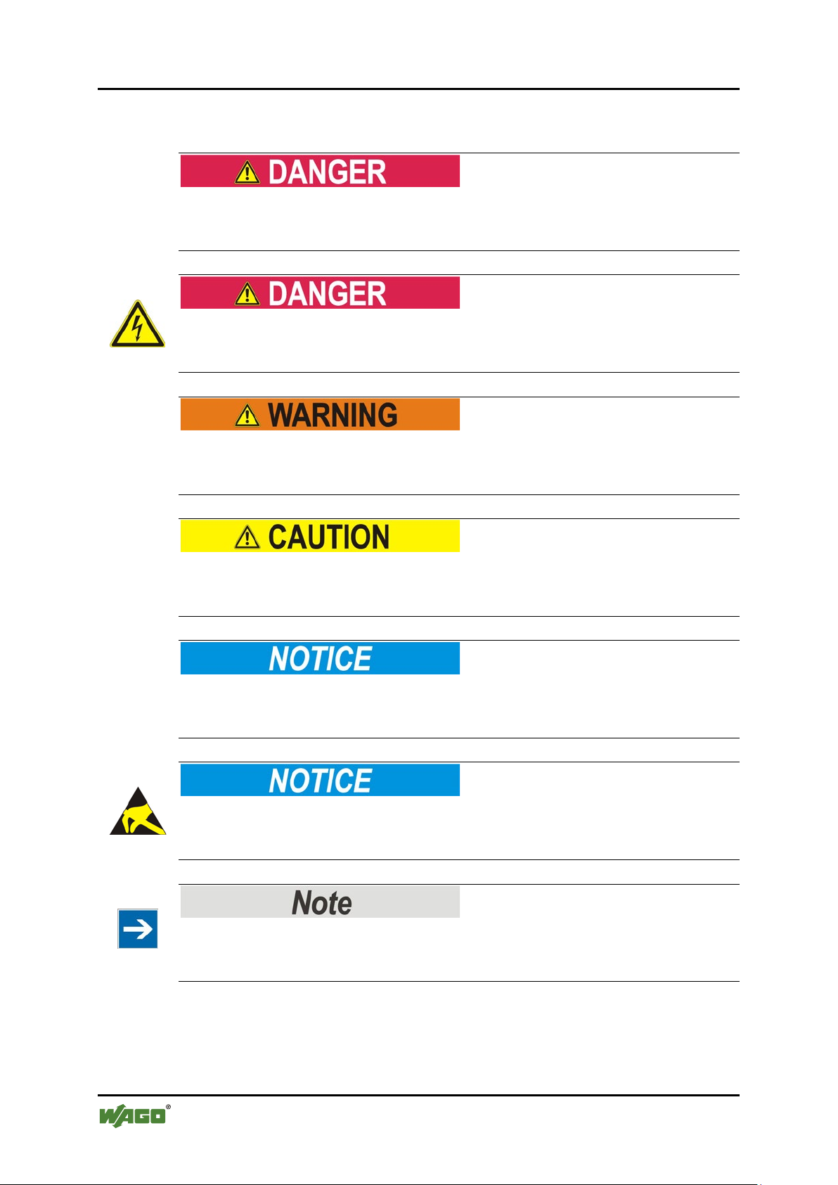
1.4 Symbols
Personal Injury!
Indicates a high-risk, imminently hazardous situation which, if not avoided, will
result in death or serious injury.
Personal Injury Caused by Electric Current!
Indicates a high-risk, imminently hazardous situation which, if not avoided, will
result in death or serious injury.
Personal Injury!
Indicates a moderate-risk, potentially hazardous situation which, if not avoided,
could result in death or serious injury.
Personal Injury!
Indicates a low-risk, potentially hazardous situation which, if not avoided, may
result in minor or moderate injury.
Damage to Property!
Indicates a potentially hazardous situation which, if not avoided, may result in
damage to property.
Damage to Property Caused by Electrostatic Discharge (ESD)!
Indicates a potentially hazardous situation which, if not avoided, may result in
damage to property.
Important Note!
Indicates a potential malfunction which, if not avoided, however, will not result in
damage to property.
Manual
Version 1.1.0, applicable from FW/HW Version 01/01
Page 7

WAGO-I/O-SYSTEM 758 Notes about this Documentation 7
758-915 Bluetooth
®
ETHERNET Gateway
Additional Information:
Refers to additional information which is not an integral part of this
documentation (e.g., the Internet).
Manual
Version 1.1.0, applicable from FW/HW Version 01/01
Page 8

8 Notes about this Documentation WAGO-I/O-SYSTEM 758
Table 2: Number notation
Number code
Example
Note
Decimal
100
Normal notation
Hexadecimal
0x64
C notation
Binary
'100'
'0110.0100'
In quotation marks, nibble separated with
dots (.)
Table 3: Font conventions
Font type
Indicates
italic
Names of paths and data files are marked in italic-type.
e.g.: C:\Programme\WAGO-I/O-CHECK
Menu
Menu items are marked in bold letters.
e.g.: Save
>
A greater-than sign between two names means the selection of a
e.g.: File > New
Input
Designation of input or optional fields are marked in bold letters,
e.g.: Start of measurement range
“Value”
Input or selective values are marked in inverted commas.
e.g.: Enter the value “4 mA” under Start of measurement range.
[Button]
Pushbuttons in dialog boxes are marked with bold letters in square
e.g.: [Input]
[Key]
Keys are marked with bold letters in square brackets.
e.g.: [F5]
758-915 Bluetooth
®
ETHERNET Gateway
1.5 Number Notation
1.6 Font Conventions
menu item from a menu.
brackets.
Manual
Version 1.1.0, applicable from FW/HW Version 01/01
Page 9

WAGO-I/O-SYSTEM 758 Important Notes 9
758-915 Bluetooth
®
ETHERNET Gateway
2 Important Notes
This section includes an overall summary of the most important safety
requirements and notes that are mentioned in each individual section. To protect
your health and prevent damage to devices as well, it is imperative to read and
carefully follow the safety guidelines.
2.1 Legal Bases
2.1.1 Subject to Changes
WAGO Kontakttechnik GmbH & Co. KG reserves the right to provide for any
alterations or modifications that serve to increase the efficiency of technical
progress. WAGO Kontakttechnik GmbH & Co. KG owns all rights arising from
the granting of patents or from the legal protection of utility patents. Third-party
products are always mentioned without any reference to patent rights. Thus, the
existence of such rights cannot be excluded.
2.1.2 Personnel Qualification
All sequences implemented on the device may only be carried out by electrical
specialists with sufficient knowledge in installation and handling of electrical
equipment. The electrical specialists must also be familiar with the current
standards and guidelines valid for the device.
2.1.3 Use in Compliance with Underlying Provisions
The device is used for wireless transmission of ETHERNET data packets per
IEEE 802.3. A radio link must be set up for this to another device, for example a
second 758-915, that also supports the Bluetooth® PAN profile.
The device has been developed for use in an environment that meets the IP65
protection class criteria. This specifies dust-tightness and protection against water
jets (nozzle) from any angle. Operation in hazardous areas is prohibited.
Manual
Version 1.1.0, applicable from FW/HW Version 01/01
Page 10

10 Important Notes WAGO-I/O-SYSTEM 758
758-915 Bluetooth
®
ETHERNET Gateway
2.2 Special Use Conditions for ETHERNET Devices
If not otherwise specified, ETHERNET devices are intended for use on local
networks. Please note the following when using ETHERNET devices in your
system:
• Do not connect control components and control networks to an open
network such as the Internet or an office network. WAGO recommends
putting control components and control networks behind a firewall.
• Limit physical and electronic access to all automation components to
authorized personnel only.
• Change the default passwords before first use! This will reduce the risk of
unauthorized access to your system.
• Regularly change the passwords used! This will reduce the risk of
unauthorized access to your system.
• If remote access to control components and control networks is required,
use a Virtual Private Network (VPN).
• Regularly perform threat analyses. You can check whether the measures
taken meet your security requirements.
• Use “defense-in-depth” mechanisms in your system's security configuration
to restrict the access to and control of individual products and networks.
2.3 Technical Condition of Specified Devices
The devices to be supplied ex works are equipped with hardware and software
configurations, which meet the individual application requirements. WAGO
Kontakttechnik GmbH & Co. KG will be exempted from any liability in case of
changes in hardware or software as well as to non-compliant usage of devices.
Please send your request for modified and new hardware or software
configurations directly to WAGO Kontakttechnik GmbH & Co. KG.
2.4 Storage, Assembly and Transport
Whenever possible, the components are to be stored in their original packaging.
Likewise, the original packaging provides optimal protection during transport.
When assembling or repacking the components, the contacts must not be soiled or
damaged. The components must be stored and transported in appropriate
containers/packaging. Thereby, the ESD information is to be regarded.
Manual
Version 1.1.0, applicable from FW/HW Version 01/01
Page 11
WAGO-I/O-SYSTEM 758 Important Notes 11
758-915 Bluetooth
®
ETHERNET Gateway
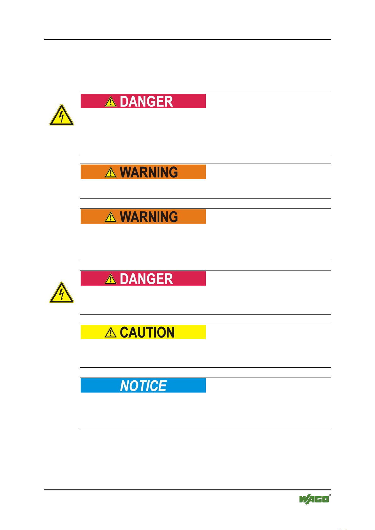
2.5 Safety Advice (Precautions)
For installing and operating purposes of the relevant device to your system the
following safety precautions shall be observed:
Always use voltage sources with current limitation/safety extra-low voltage!
Only use power supply sources based on IEC/EN60950 Section 2.5 “Power
sources with limited output” with the device. The output of the external power
supply must be short-circuit protected. The output voltage of the external power
supply shall not exceed 30 VDC.
Do not use device in hazardous environments!
The device is not designed for use in hazardous areas.
Maintenance/Repair only by authorized specialists!
The device contains no parts that can be serviced by users. Always have all
service, reconfiguration, maintenance or repair work performed by specialists
authorized by WAGO.
Do not work on components while energized!
All power sources to the device shall be switched off prior to performing any
installation, repair or maintenance work.
Keep a distance of 20 cm to persons!
Install the device such that it is located at least 20 cm away from all persons
during operation.
Replace defective or damaged devices!
Replace defective or damaged device (e.g., in the event of deformed contacts),
since the long-term functionality of fieldbus station involved can no longer be
ensured.
Manual
Version 1.1.0, applicable from FW/HW Version 01/01
Page 12
12 Important Notes WAGO-I/O-SYSTEM 758
758-915 Bluetooth
®
ETHERNET Gateway
Protect the components against materials having seeping and insulating
properties!
The components are not resistant to materials having seeping and insulating
properties such as: aerosols, silicones and triglycerides (found in some hand
creams). If you cannot exclude that such materials will appear in the component
environment, then install the components in an enclosure being resistant to the
above-mentioned materials. Clean tools and materials are imperative for handling
devices/modules.
Cleaning only with permitted materials!
Clean soiled contacts using oil-free compressed air or with ethyl alcohol and
leather cloths.
Avoid electrostatic discharge!
The devices are equipped with electronic components that you may destroy by
electrostatic discharge when you touch. Pay attention while handling the devices
to good grounding of the environment (persons, job and packing).
Device uses radio waves!
Never use the device in areas where operation of radio equipment is prohibited.
Do not open the enclosure!
Never open the enclosure. Opening of the enclosure will nullify the guarantee,
legal warranty and authorization for use.
Manual
Version 1.1.0, applicable from FW/HW Version 01/01
Page 13
WAGO-I/O-SYSTEM 758 Device Description 13
758-915 Bluetooth
®
ETHERNET Gateway
3 Device Description
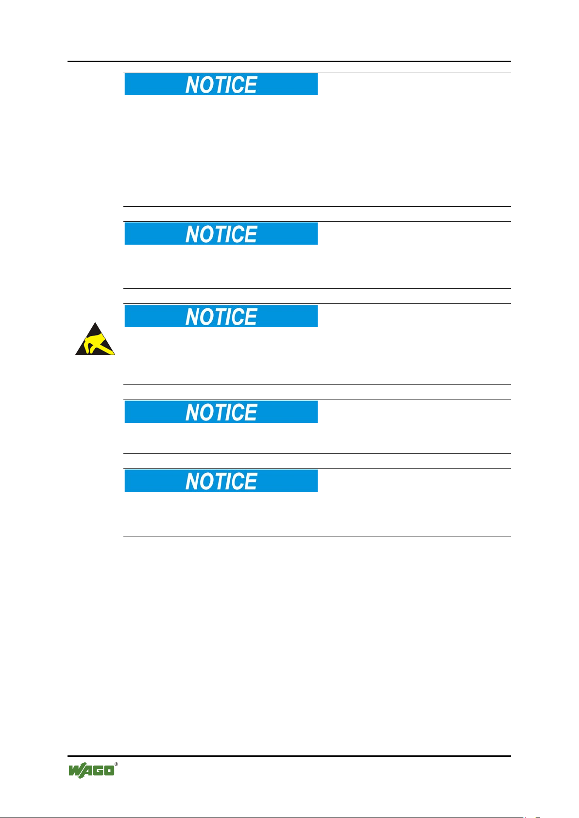
The Bluetooth® ETHERNET gateway 758-915 (“WEG” – Wireless ETHERNET
gateway) enables ETHERNET devices to be linked to a wireless Bluetooth®
network, in which the data received via the ETHERNET interface is transmitted
via Bluetooth®. In the other direction, data received at the Bluetooth® interface is
transmitted via the ETHERNET interface. As data transmission of ETHERNET
packets occurs with a transparent protocol on Layer 2 of the OSI reference model,
this provides for easy integration of all Ethernet-based fieldbuses, such as
MODBUS/TCP, ETHERNET/IP, PROFINET or PROFISAFE.
Together with a further Bluetooth® PAN profile compliant device with Ethernet
capabilities, such as a further WEG or a Bluetooth® access point (AP), the WEG
can also be used as a wireless substitute for ETHERNET cables. As a Bluetooth®
Class 1 device with additional, special functions implemented which enhance
coexistence, the WEG provides particularly robust, real-time-capable radio links
over long distances without any adverse impact on other radio networks, such as
WLAN (IEEE 802.11 b/g).
Bluetooth
between 2 WEGs
®
transmission
Network 1 Network 2
Figure 1: Bluetooth
®
transmission between 2 WEGs
An innovative operator control concept enables easy initiation of automatic
configuration processes using a Mode membrane key on the device. This can be
used to configure a substitute cable link between two WEGs in only a few
seconds, without using additional aids or hardware / software.
In addition to operation using the Mode membrane key and the 7 LED status
indicators, access to other status information and advanced device functions of the
WEG is also possible via a Web-based management system (WBM).
The WEG supports the “Simple Network Management Protocol” (SNMP).
Besides the object IDs (OIDs) for the RFC1213, the device also provides access to
further device-specific parameters. A corresponding description file for the
“Management Information Base” (MIB) is available from WAGO Support.
Manual
Version 1.1.0, applicable from FW/HW Version 01/01
Page 14
14 Device Description WAGO-I/O-SYSTEM 758
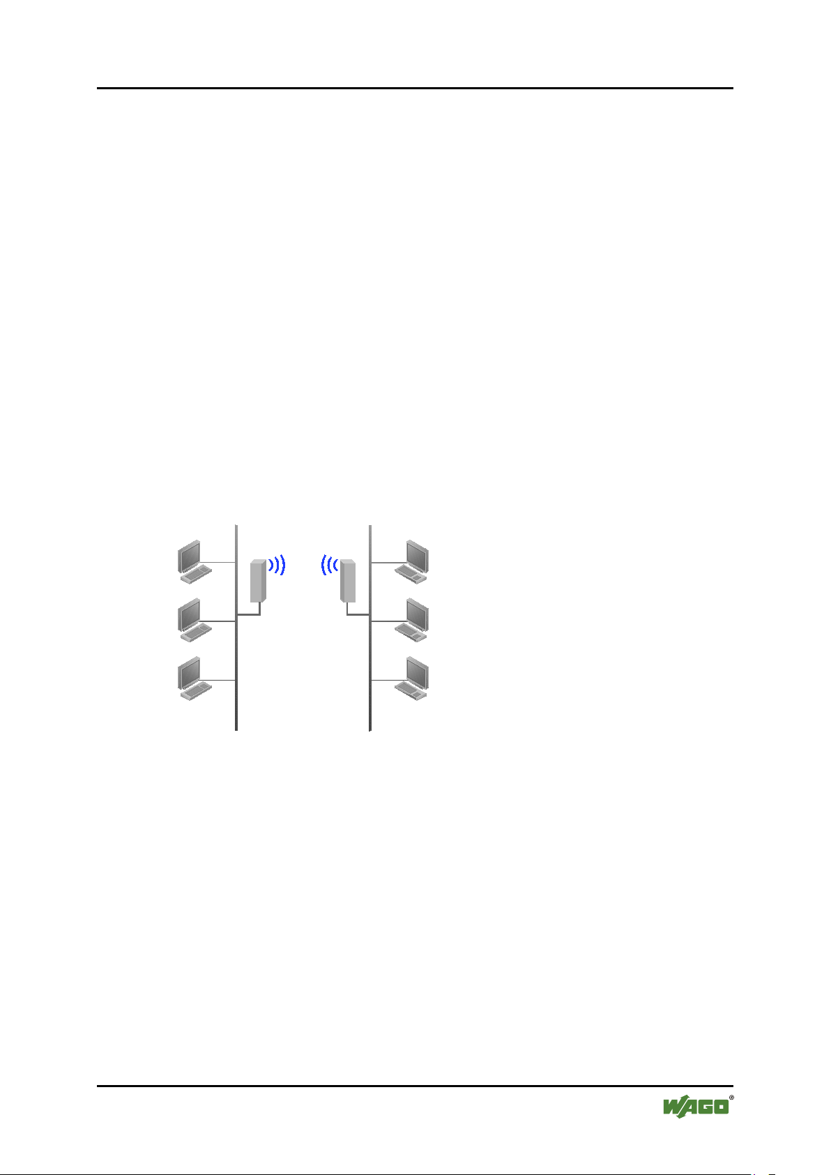
Table 4: Legend for the “View” figure
No.
Description
Details see Section:
1
Status and diagnosis LEDs (front)
“Display Elements”
2
Internal circular polarized directional antenna 5 dB
“Connectors”
3
Fixing hole 1
“Mounting”
4
LEDs for link quality indication (bottom),
configuration and status indication
“Display Elements”
5
Mode membrane key for configuration
“Operating Elements”
6
Network connection, M12 socket on device
“Connectors”
7
Power supply, M12 connector on device
“Connectors”
8
Fixing hole 2
“Mounting”
758-915 Bluetooth
®
ETHERNET Gateway
3.1 View
Figure 2: View
Manual
Version 1.1.0, applicable from FW/HW Version 01/01
Page 15
WAGO-I/O-SYSTEM 758 Device Description 15
758-915 Bluetooth
®
ETHERNET Gateway
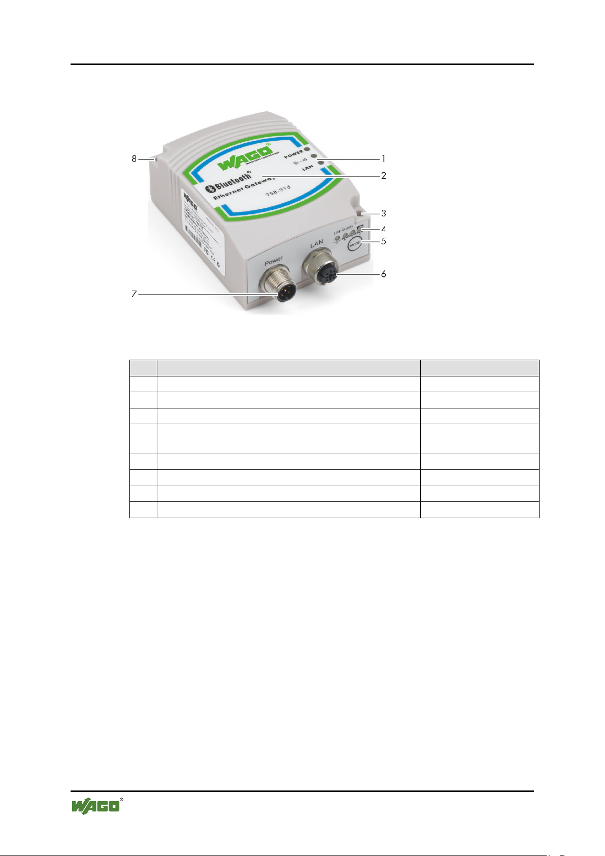
3.2 Labeling
The status indicators for (POWER, (((.))), LAN) are marked on the front of the
device.
Figure 3: Marking on front of device
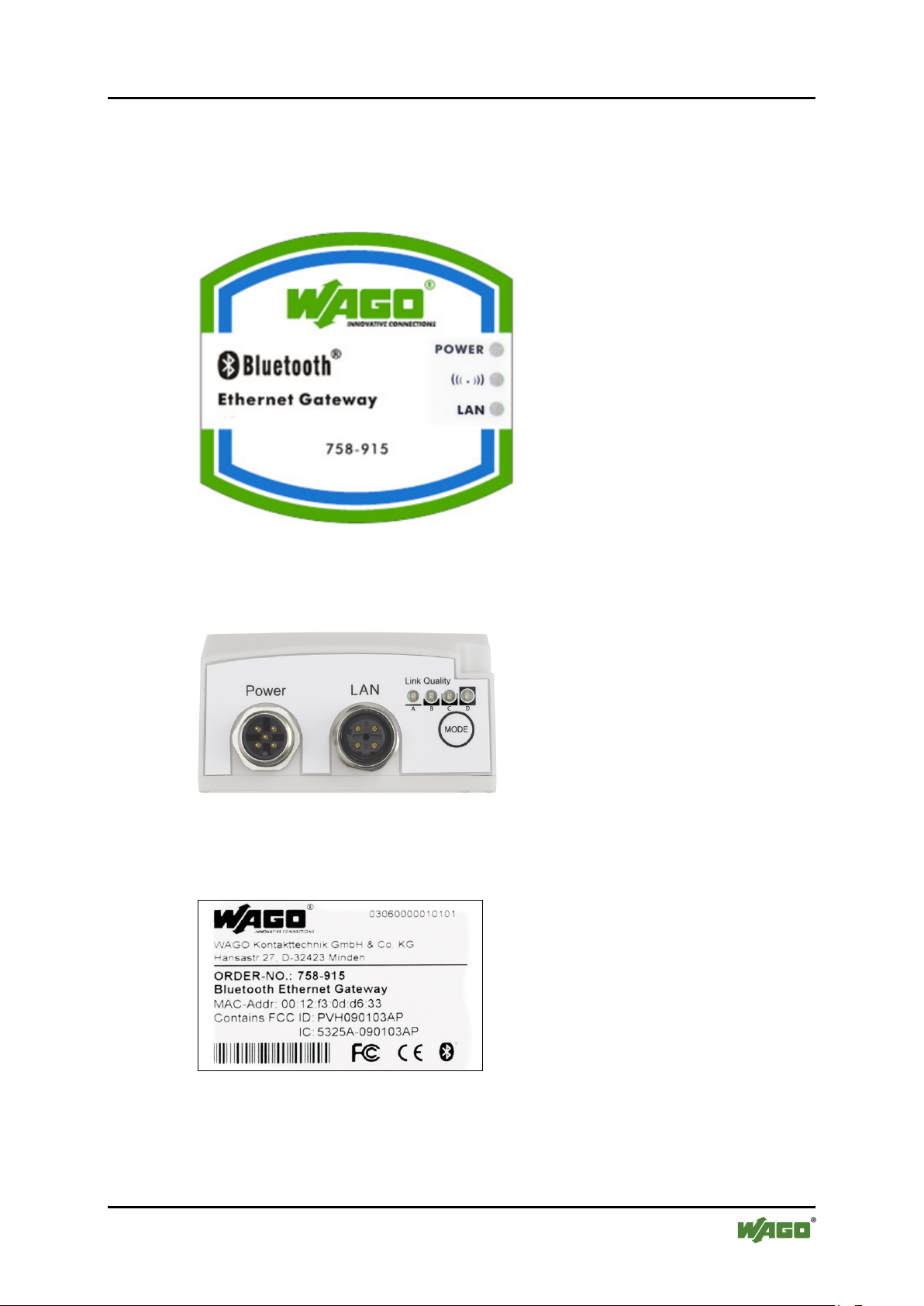
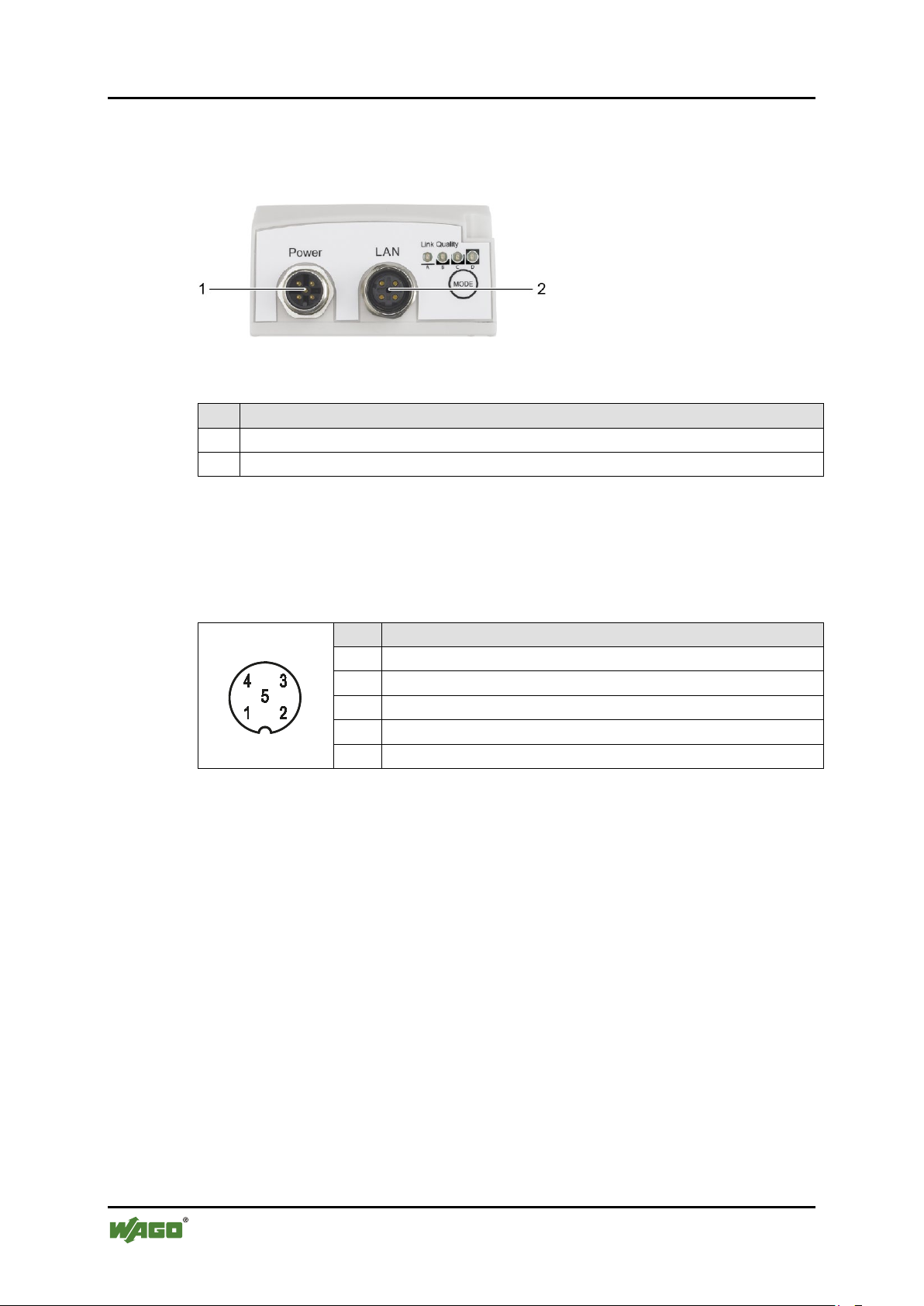
The connections (Power, LAN), link quality and configuration button (Mode) are
marked on the bottom of the device.
Figure 4: Marking on bottom
The device MAC address is included with other device data on the nameplate on
the back or side of the device.
Figure 5: Nameplate on back/side
Manual
Version 1.1.0, applicable from FW/HW Version 01/01
Page 16
16 Device Description WAGO-I/O-SYSTEM 758
Table 5: Legend for the “Connections at bottom of device” figure
No.
Description
1
Power supply and trigger input (“Power”)
2
Network connection (“LAN”)
Table 6: Power supply, M12 Connector on Device
Pin
Pin assignment
1
Vin + (9 V … 30 VDC)
2
Trigger input ground
3
Vin Ground (0 V)
4
Trigger-input + (9 V … 30 VDC)
5
Not in use
758-915 Bluetooth
®
ETHERNET Gateway
3.3 Connectors
The device is equipped with two connections at the bottom:
Figure 6: Connections at bottom of device
3.3.1 Pin Assignment for Power Supply
Power is supplied to the device via a 5-pole, A-coded M12 connector.
The trigger input reacts to rising flanks and can be used for setting up and
terminating radio links (see Section “Configuration using the Mode membrane
button” / “Configuration via the Web-based Management System (WBM)”).
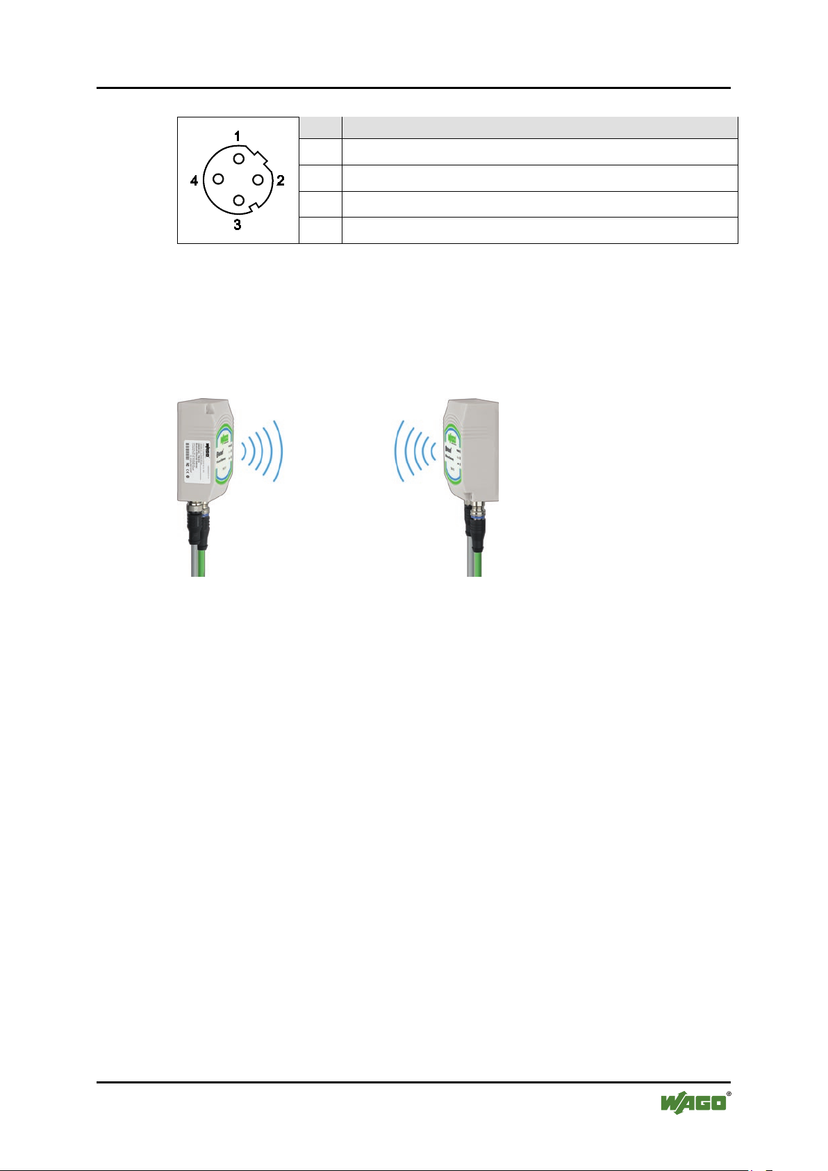
3.3.2 Pin Assignment for System Connection
The device is connected to the ETHERNET network via a 4-pole, D-coded socket
and supports autonegotiation for 10/100 Mbit and the duplex mode.
Manual
Version 1.1.0, applicable from FW/HW Version 01/01
Page 17
WAGO-I/O-SYSTEM 758 Device Description 17
Table 7: System connection, M12 Socket on Device
Pin
Pin assignment
1
Transmit +
2
Receive +
3
Transmit -
4
Receive -
758-915 Bluetooth
®
ETHERNET Gateway
3.3.3 Antenna
The device is equipped with an antenna. Good reception conditions exist when the
front of the device is oriented centered to the remote device with which the radio
link is to be established.
Figure 7: Aligning the device
As the device comes equipped with a circular polarized antenna, rotation of the
device around the link axis between the local and remote device does not have any
adverse impact on link quality.
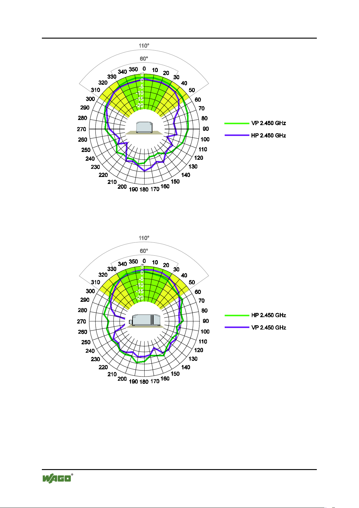
The directional alignment (antenna) diagrams for the antenna are given in the
following figures for a frequency of 2.450 GHz.
The horizontal diagram illustrates the two-dimensional top view of the
electromagnetic field of the antenna, with the antenna being the center point. At a
beam angle of around 60° the antenna provides excellent reception levels;
reception continues to be good up to an angle of 90°, whereas reception markedly
deteriorates at beam angles of 110° and greater.
Manual
Version 1.1.0, applicable from FW/HW Version 01/01
Page 18
18 Device Description WAGO-I/O-SYSTEM 758
758-915 Bluetooth
®
ETHERNET Gateway
Figure 8: Antenna diagram – Horizontal 2.450GHz
The vertical antenna diagram shows the side view of the antenna's
electromagnetic field.
Figure 9: Antenna diagram – Vertical 2.450GHz
The alignment characteristic for the internal antenna is primarily relevant for links
in the open field and over long distances. When operating the device at short
distances, inside buildings or without line-of-sight links structural conditions are
the decisive factor for good reception.
Manual
Version 1.1.0, applicable from FW/HW Version 01/01
Page 19
WAGO-I/O-SYSTEM 758 Device Description 19
Table 8: Legend for the “Display elements” figure
Nr.
Designation
Color
Status
Meaning
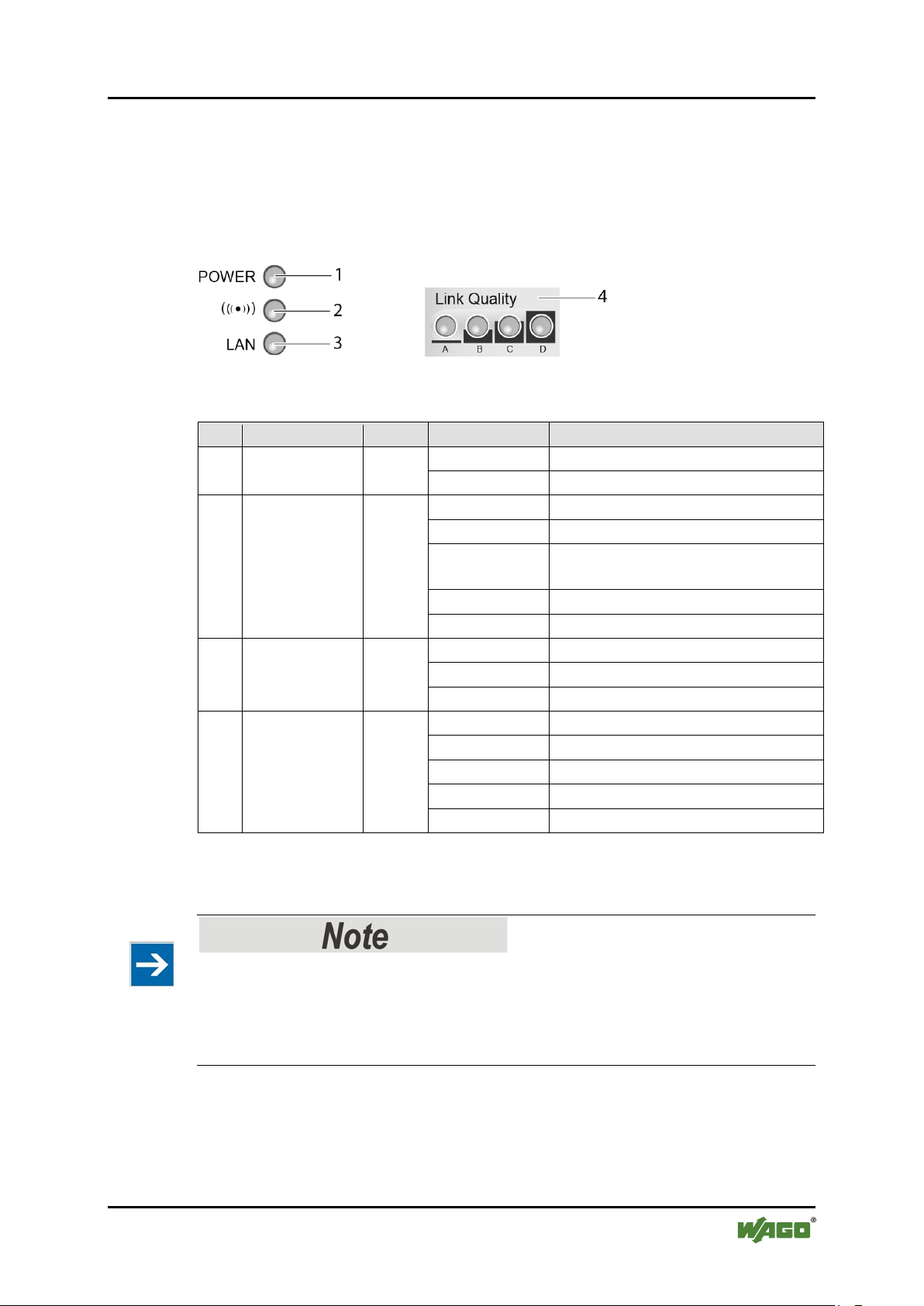
On
Device ready for operation
Off
Device not ready for operation
Blue
Bluetooth® link active
Blue flashing
Data transmission
Purple
Setting up link to other Bluetooth®
device
Red
Error
Off
No Bluetooth® link available
On
ETHERNET link available
Blinking
ETHERNET communication active
Off
No ETHERNET link available
A on
Acceptable link quality
A+B on
Good link quality
A+B+C on
Optimal link quality
A+B+C+D on
Excellent link quality
Off
No Bluetooth® link available
*
Status signals are also indicated via LEDs A to D during configuration. In this case, the indicators
membrane button”.
758-915 Bluetooth
®
ETHERNET Gateway
3.4 Display Elements
The current device status is indicated by the three LEDs on the front of the WEG.
Four other LEDs at the bottom of the device indicate the link quality, or the
selected autoconfiguration procedure.
Figure 10: Display elements
1
Power
green
blue
2
((( . )))
purple
red
3
LAN
Link
4
Quality*
will differ from the status information given here, see Section “Configuration using the Mode
yellow
green
Observe the operating mode!
The indicators for (((.))) and LAN are only valid when the power LED signals
“Device ready for operation”. In special modes, such as device initialization or
firmware update, the LEDs mentioned previously may respond differently than
described above.
Manual
Version 1.1.0, applicable from FW/HW Version 01/01
Page 20
20 Device Description WAGO-I/O-SYSTEM 758
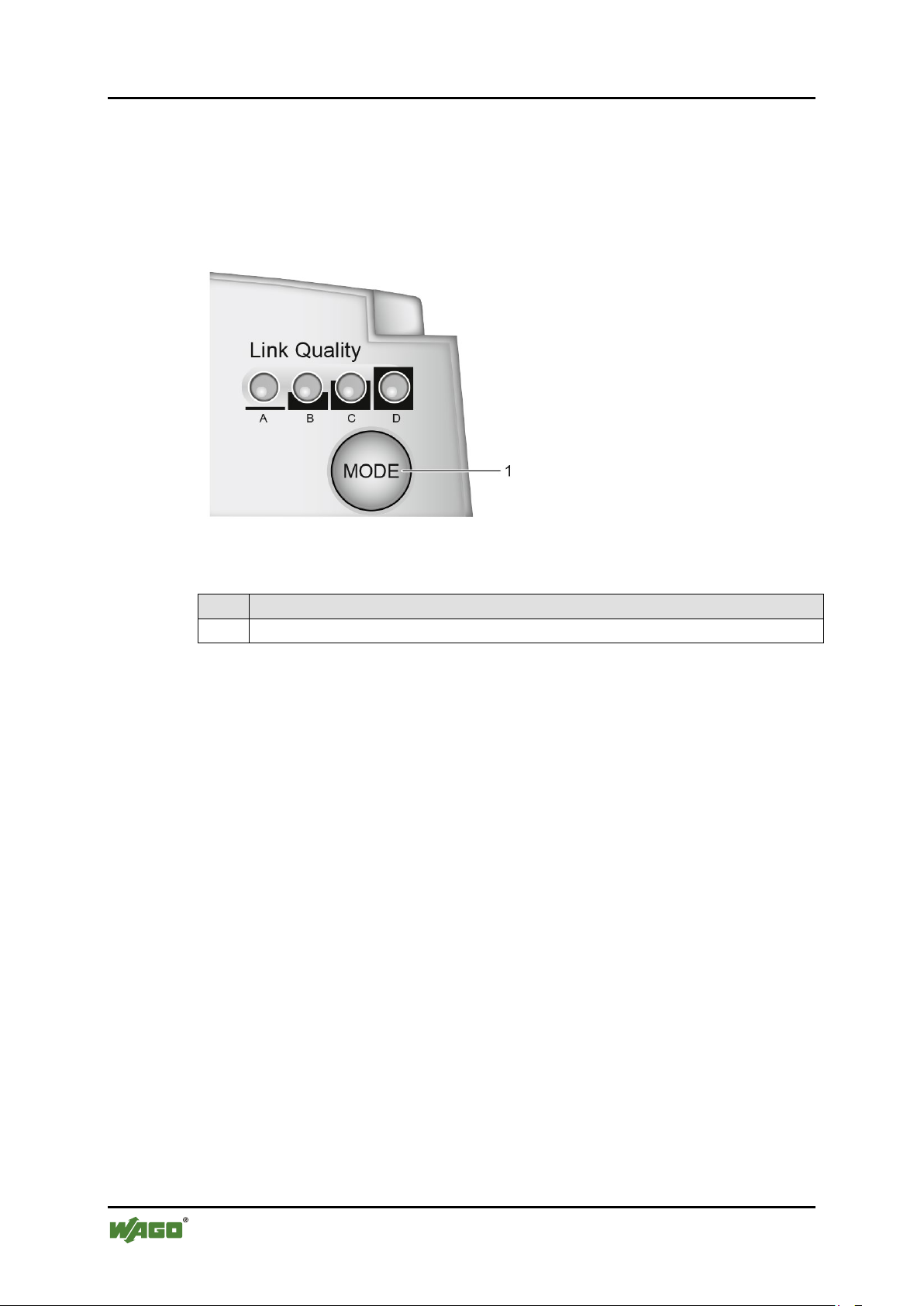
Table 5: Legend for the “Operating element” figure
No.
Description
1
Mode membrane button
758-915 Bluetooth
®
ETHERNET Gateway
3.5 Operating Elements
The “Mode” membrane button is located at the bottom of the device. This button
is used to initiate certain autoconfiguration procedures. LEDs A to D indicate
which procedure is active. For more information about this refer to the Section
“Configuration using the Mode membrane button”.
Figure 11: Operating element
Manual
Version 1.1.0, applicable from FW/HW Version 01/01
Page 21

WAGO-I/O-SYSTEM 758 Device Description 21
Table 9: Technical Data – Device Data
Function
Bluetooth® ETHERNET Gateway
Dimensions (mm)
W x H x D
66 x 91 x 36
Weight
120 g
Ports
Power connector:
M12 plug, A-coded
ETHERNET connector:
M12 socket, D-coded
Operating temperature
-30 °C ... + 65 °C
Storage temperature
-40 °C ... + 85 °C
Degree of protection
IP65
Relative humidity
(without condensation)
95 %
Connection to PE
not required
Fitting position
On a level mounting surface
Free from silicone
Yes
RoHS-compliant
Yes
Configuration
Via Web-based Management System
or using the Mode membrane button
Immunity to interference
Static discharge based on EN 61000-4-2:
Air discharge ± 8 kV
Electromagnetic fields based on IEC61000-4-3:
10 V/m, Criterion A
Mains borne disturbance based on IEC 61000-4-6:
10 V RMS, Criterion A
Rapid transients (burst) based on IEC 61000-4-4:
Power supply: 2 kV
Surge voltage based on IEC 61000-4-5:
Power supply: ± 0.5 kV
Emission of interference
per EN 55022 Class B (residential areas)
Mechanical stability
Schock test based on IEC 60068-2-27
Storage/Transport 50 g, duration 11 ms
Vibration test based on IEC 60068-2-6
Operation 5 g, 10-150 Hz, Criterion 3
Free fall based on IEC 60068-2-32
1 m
758-915 Bluetooth
®
ETHERNET Gateway
3.6 Technical Data
3.6.1 Device Data
Contact discharge ± 4 kV
Data interface: 1 kV
Data interface: ± 1 kV
Operation 25 g, duration 11 ms
Manual
Version 1.1.0, applicable from FW/HW Version 01/01
Page 22

22 Device Description WAGO-I/O-SYSTEM 758
Table 10: Technical Data – ETHERNET Interface
Number of inputs
1 (trigger input)
Medium
Via M12, twisted pair wire, wire cross section
0.14 mm² … 0.22 mm²
Baud rate
10/100 MBit/s, Autonegotiation
Default IP address
192.168.1.99
Default subnet mask
255.255.255.0
Table 11: Technical Data – Bluetooth® Interface
Bluetooth® version
Bluetooth® 2.0
based on IEEE 802.15.1; 2.4 GHz, max. 1 MBit/s
RF transmitting power
Bluetooth® Class 1
RF input sensitivity
-85 dBm at BER 0.1%
Wireless connections
1
Antenna
Internal directional antenna 5 dBi
(non-exchangeable)
Transmission range
Up to 400 m (class 1)
Topology
Point-to-point
Bluetooth® Profile
PAN, PANU
Coexistence
FHSS with AFH and/or user-defined channel
Low Emission Mode™
Security
Bluetooth® security mode 3 supported, 128-bit
PIN, non-discoverable mode
Table 12: Technical Data – Power Supply
Power supply connection
Via M12, max. wire cross section 2.5 mm²
Nominal Voltage
24 VDC (SELV)
Voltage range, permissible
9 V to 30 VDC
Current consumption, typical
65 mA at 24 VDC
Current consumption, maximum
200 mA at 24 V
758-915 Bluetooth
®
ETHERNET Gateway
3.6.2 ETHERNET Interface
3.6.3 Bluetooth® Interface
3.6.4 Supply
mask, adjustable transmitting power,
encryption, authentication,
Manual
Version 1.1.0, applicable from FW/HW Version 01/01
Page 23

WAGO-I/O-SYSTEM 758 Device Description 23
Conformity Marking
R&TTE
Complaint with 1999/5/EG directive (per Article 3.2)
Bluetooth®
IC „Industry Canada“
IC: 5325A-090103AP
FCC "Federal Communications Commission"
/ CFR 47 Part 15, ETS 300328
FCC ID: PVH090103AP
This device complies with Part 15 of the FCC Rules. Operation is subject to the following two conditions:
received, including interference that may cause undesired operation.
758-915 Bluetooth
®
ETHERNET Gateway
3.7 Approvals
(1) this device may not cause harmful interference, and (2) this device must accept any interference
With the exception of Andorra, Bulgaria, France and Latvia, the device may be
used without restrictions in all European countries and in Switzerland, the USA
and Canada.
The device may be used inside buildings in Bulgaria.
In France, the transmitting power must be limited to 10 dBm when used outside of
buildings. In Norway the device may not be used with a radius of 20 km of the
town center of Ny-Âlesund (Spitzbergen).
Manual
Version 1.1.0, applicable from FW/HW Version 01/01
Page 24

24 Mounting WAGO-I/O-SYSTEM 758
758-915 Bluetooth
®
ETHERNET Gateway
4 Mounting
4.1 Selecting the Installation Location
In order to use all the functions of the WEG, a radio link must be established to a
device having similar functions, for example a second WEG of the same type. If
the two devices are relatively close to one another, that is, if the distance between
them is considerably less than the potential range, the installation location and
device alignment will have comparatively little impact on the radio link. If you
wish to set up and maintain a radio link over the longest distance possible,
however, certain requirements regarding the installation of the device and the
ambient conditions must be fulfilled.
The distance between devices may not be too great. The maximum range can only
be effective under optimal conditions. A lack of line-of-sight link, or misalignment of the devices will result in reduced range.
For a line-of-sight link, install the devices such that the antennas are aligned
toward one another, i.e., the marked front side of the devices face one another (see
also the figure and the antenna diagrams in the section “Connectors” >
“Antenna”).
If there is no line-of-sight link, but both devices have an unobstructed view of the
same metallic or concrete surface (such as a building ceiling), a good radio link
can be ensured through reflection.
If there is neither a line-of-sight link, nor a surface to use for reflection, for
example between devices in different rooms, align the devices as for a line-ofsight link. The magnitude of the reduction in range for the devices in this case
depends on the amount of material, e.g., brick walls, that the radio waves must
pass through. In some circumstances, it may not be possible for the radio waves to
penetrate certain obstacles, such as fire protection walls, at all.
Manual
Version 1.1.0, applicable from FW/HW Version 01/01
Page 25

WAGO-I/O-SYSTEM 758 Mounting 25
Table 13: Selection of Installation Location
Ambient Conditions, Installation Location
Radio link possible?
Distance between devices is more than 400 m.
No
Line-of-sight link between devices that are about
installed and configured.
Yes
Two plaster or brick walls are located between
Yes. Links are also possible
a wall).
A fire protection wall or a steel-reinforced
No. Reinforced concrete and
when they are too thick.
The devices are located less than 50 m apart in a
Possible. Building ceilings or
reflecting the radio waves.
758-915 Bluetooth
®
ETHERNET Gateway
200 m apart. Devices have been optimally
the devices; distance between devices is around
30 m.
concrete ceiling is located between the devices.
plant building, with the line of sight being
obstructed by numerous machines or vehicles.
without line of sight, but the
range is substantially reduced,
depending on the obstacle (e.g.,
other similar materials cannot
be penetrated by radio waves
other metallic or steelreinforced large objects may
permit an indirect link by
Manual
Version 1.1.0, applicable from FW/HW Version 01/01
Page 26

26 Mounting WAGO-I/O-SYSTEM 758
758-915 Bluetooth
®
ETHERNET Gateway
4.2 Fixing
Always maintain a minimum distance of 50 cm between two WEGs!
Always maintain a distance of at least 50 cm between WEGs when installing
them. Radio link quality can be degraded on failure to maintain this distance.
Do not install antenna directly in front of metallic surfaces!
The front of the WEG, and hence the internal antenna, shall not be located
directly in front of metallic surfaces, as this can permanently degrade the radio
capabilities of the antenna.
Use the drilled holes (see drawing below), for example, and the two M3 screws to
attach the WEG to any flat, level surface.
Figure 12: Drilled holes for attaching the WEG
Manual
Version 1.1.0, applicable from FW/HW Version 01/01
Page 27

WAGO-I/O-SYSTEM 758 Connect Devices 27
758-915 Bluetooth
®
ETHERNET Gateway
5 Connect Devices
5.1 Connection
Before the device can be used, all cable connections must be established.
Ensure that wires are not live!
Power supply: Do not switch on the power supply until the device has been
properly connected.
LAN: Improperly routed ETHERNET cables can carry dangerous overvoltage.
Always ensure that these cables have been laid properly before connecting the
device to the network.
1. Use a suitable cable, such as WAGO Item 756-1203/060-050, to connect the
WEG to your network or ETHERNET terminal.
2. Use a suitable cable, such as WAGO Item 756-3101/040-020, to connect the
WEG to the external power supply unit.
Figure 13: Connecting the WEG
Manual
Version 1.1.0, applicable from FW/HW Version 01/01
Page 28

28 Commissioning WAGO-I/O-SYSTEM 758
758-915 Bluetooth
®
ETHERNET Gateway
6 Commissioning
The device is not equipped with a power switch, meaning it is put into operation
simply by applying power.
Use the correct supply voltage!
The output of the power supply unit must provide 24 VDC with a maximum
current flow of 200 mA.
Switch on the external power supply unit to put the device into operation.
Manual
Version 1.1.0, applicable from FW/HW Version 01/01
Page 29

WAGO-I/O-SYSTEM 758 Configuration 29
Table 14: Default Settings
Group
Subgroup
Parameter
Default value
Network
IP configuration
IP address
192.168.1.99
Network
IP configuration
Subnet mask
255.255.255.0
Network
IP configuration
Default gateway
192.168.1.99
Network
IP configuration
Receive IP via DHCP
No
Bluetooth
General
Operation mode
PANU
Bluetooth
General
Device name
“BTEG”
Bluetooth
Security
Passkey
“0000”
Bluetooth
Security
Security mode
On
Bluetooth
Security
Visible for other devices
Yes
Bluetooth
WLAN coexistence
Low emission mode
Off
Bluetooth
WLAN coexistence
Exclude WLAN channel
None
Bluetooth
Connection
Bluetooth address
(blank)
Bluetooth
Connection
Device name
(blank)
Bluetooth
Connection
Remote role
Panu
Bluetooth
Roaming
Link sensitivity
Medium
Bluetooth
Roaming
Connect to name scheme
Name
System
Security
Password
“wago”
758-915 Bluetooth
®
ETHERNET Gateway
7 Configuration
After you have connected the WEG you can configure it in one of two ways:
• using the Mode membrane button and by activating certain modes
• by making settings via the Web-based Management System (WBM)
The various types of configuration are described in the following sections.
If the device has already been configured and you are not familiar with the current
configuration, we recommend resetting the device to its factory default settings
before making any further configuration settings. This can be done using the
Mode membrane button.
7.1 Default settings
The following settings are active on initial startup of the WEG:
Manual
Version 1.1.0, applicable from FW/HW Version 01/01
You can always restore the factory default settings at any time using the Mode
membrane button (see following section). This can be useful, for example, if you
have forgotten the IP address or the device AT password.
Page 30

30 Configuration WAGO-I/O-SYSTEM 758
Table 15: Autoconfiguration Procedures
Press
758-915 Bluetooth
®
ETHERNET Gateway
7.2 Configuration Using the Mode Membrane Button
The quickest and easiest method for configuring the device is using the Mode
membrane button located at the bottom of the device. LEDs A to D indicate the
status during configuration, based on the active operating mode. By repeatedly
pressing the Mode membrane button you can select and start an autoconfiguration
procedure in the device that then automatically carries out the device
configuration for the required scenario.
Figure 14: Mode membrane button and status LEDs
7.2.1 Overview of Autoconfiguration Procedures
The following autoconfiguration procedures can be selected in the order given:
1 x
2 x
3 x
Autoconfiguration Procedures LED A B C D
1 Exit configuration mode
Exit the configuration mode without saving changes made
to the device configuration.
1 Reset device to factory default settings
Restore all settings to the factory default settings.
2 Reset IP parameters
Restore the IP parameters to the factory default settings.
All other settings are retained.
button
A
B
A+B
4 x
Manual
Version 1.1.0, applicable from FW/HW Version 01/01
3 Wait for automatic configuration
The device will wait for configuration by a different WEG.
Although the device is connectable, it will not initiate the
setting up of a link.
C
Page 31

WAGO-I/O-SYSTEM 758 Configuration 31
Table 15: Autoconfiguration Procedures
Press
758-915 Bluetooth
®
ETHERNET Gateway
5 x
6 x
Autoconfiguration Procedures LED A B C D
®
4 Initiate automatic configuration via Bluetooth
WEG-WEG bridge
The WEG automatically sets up a link to a different WEG
that is in the configuration mode “Wait for automatic
configuration” (LED C) and then configures that WEG.
6 Initiate automatic configuration via Bluetooth
WEG-WEG bridge with PROFINET-/PROFISAFE
optimization
The WEG automatically sets up a link to a different WEG
that is in the configuration mode “Wait for automatic
configuration” (LED C) and then configures that WEG.
,
A+C
®
,
B+C
button
On configuration using the Mode membrane button, only those parameters
required for the particular autoconfiguration will be overwritten.
You can initially make changes via the Web-based Management System and then,
for example, inhibit WLAN channels that are not to be used (“Channel skipping”).
These changes also remain effective after one of the automatic configurations 3, 4,
5 or 6.
Autoconfiguration procedures 1 to 3 always become effective; procedures 2 and 3
change the device configuration immediately.
Autoconfiguration procedures 4 to 6 only change the device configuration when a
radio link has been successfully established. If the WEG loses power before the
autoconfiguration has been completed, or if no other WEG can be contacted via
the radio link within 5 minutes for automatic configuration, the device will retain
its previous configuration settings when it is restarted.
The following settings are overwritten in the course of the various
autoconfiguration procedures:
Manual
Version 1.1.0, applicable from FW/HW Version 01/01
Page 32

32 Configuration WAGO-I/O-SYSTEM 758
Table 16: Overwriting of Configuration
Autoconfigurati
on procedure
Changes to Configuration on Successful Setup of Link
1
No changes made.
2
All settings are changed.
3
• Network > IP-Address: 192.168.1.99
• Network > Gateway: 192.168.1.99
4
Remote device using autoconfiguration procedure 5 or 6 (Initiate link
5, 6
Autoconfiguration procedure 5 and 6:
758-915 Bluetooth
®
ETHERNET Gateway
• Network > Subnet Mask: 255.255.255.0
setup):
• Network > IP-Address: 192.168.1.99
• Network > Subnet Mask: 255.255.255.0
• Network > Gateway: 192.168.1.99
• Bluetooth > Security > Passkey: (Random value, but identical to the partner
device)
• Bluetooth > Security > Security Mode: On
• Bluetooth > Security > Visible: No
• Bluetooth > Connection > Device Name: (blank)
• Miscellaneous > Send AT command: > ATS1007=1250 > Send
Also effective when partner device is using autoconfiguration mode 6:
• De-activate the Web-based Management System
• Activate PROFINET optimization
• Network > IP-Address: 192.168.1.100
• Network > Subnet Mask: 255.255.255.0
• Network > Gateway: 192.168.1.99
• Bluetooth > Security > Passkey: (Random value, but identical to the partner
device)
• Bluetooth > Security > Security Mode: On
• Bluetooth > Security > Visible: No
• Bluetooth > WLAN coexistence > Low emission mode: On
• Bluetooth > Connection > Device Name: (blank)
• Bluetooth > Connection > Device Address: Device address of partner
device
• Miscellaneous > Send AT command: > ATS1007=1250 > Send
Also with autoconfiguration procedure 6:
• De-activate the Web-based Management System
• Activate PROFINET optimization
Manual
Version 1.1.0, applicable from FW/HW Version 01/01
Page 33

WAGO-I/O-SYSTEM 758 Configuration 33
758-915 Bluetooth
®
ETHERNET Gateway
Enable de-activated WBM using the Mode membrane button!
If autoconfiguration is conducted with PROFINET optimization, the device deactivates the Web-based Management System to provide short cycle times.
Consequently, configuration can only be changed using the Mode membrane
button. Reset the device to the factory default settings to enable access to the
Web-based Management System again.
7.2.2 Selection and Activation of an Autoconfiguration Procedure
General procedure:
1. Switch off the power supply to the WEG and then re-activate power supply
to the device.
The Power LED lights up.
2. Within the first 5 seconds after applying power, press the Mode membrane
button to switch to the operating mode “Configuration selection”.
LED A lights up and the operating mode “Configuration selection” is active.
If this is not the case, repeat steps 1 and 2.
3. Select the autoconfiguration procedure:
Select the required autoconfiguration procedure by pressing the Mode
membrane button until the appropriate combination of LEDs lights up (see
previous section “Overview of Autoconfiguration Procedures”).
If you have switched through all the operating modes in order, you can
return to the first option in the order by pressing the button again.
Configuration is halted if the Mode membrane button is not pressed for 20 s!
The mode “Configuration selection” is de-activated automatically if you do not
press the Mode membrane button for selecting the autoconfiguration procedure.
The WEG will then start up using the previous settings.
4. Activate autoconfiguration procedure:
To execute the selected autoconfiguration procedure press the Mode
membrane button again and hold it in for at least 2 seconds until the LED
indicators A-D or the Power LED change.
Manual
Version 1.1.0, applicable from FW/HW Version 01/01
Page 34

34 Configuration WAGO-I/O-SYSTEM 758
Procedures 1, 4, 5, 6:
The LEDs A-D corresponding to the procedure will flash
disconnecting the power supply from the device.
Procedures 4, 5, 6 also end automatically on successful
configuration of a link, or after a timeout of 5 minutes.
Procedures 2, 3:
The device carries out the changes to the configuration and
This only takes a few seconds.
758-915 Bluetooth
®
ETHERNET Gateway
Autoconfiguration procedure execution:
The device performs a restart as soon as the procedure has been completed
successfully or canceled.
The behavior of the device up to this restart is based on the active
autoconfiguration procedure:
until the procedure is concluded. All of these procedures
can also be manually terminated prematurely by pressing
the Mode membrane button again, or by briefly
ends the procedure directly after this.
The LEDs return to their normal status on conclusion of the autoconfiguration
procedure.
Figure 15: Flow chart
Manual
Version 1.1.0, applicable from FW/HW Version 01/01
Page 35

WAGO-I/O-SYSTEM 758 Configuration 35
758-915 Bluetooth
®
ETHERNET Gateway
7.3 Configuration using the Web-based Management System (WBM)
A Web-based Management System (WBM) is available on an integrated Web
server for configuring the WEG.
You can go the WBM by entering the IP address of the device in the browser
URL line.
Device configuration is password protected. If you have forgotten the IP address
or password you can reset the device to its factory default settings.
On initial commissioning, the device uses the static IP address and the default
settings password (see Section “Default Settings”). You may have to modify the
IP configuration of the PC from which you are accessing the WBM before a link
can be set up.
7.3.1 Accessing the Web-based Management System
1. To open the WBM, launch a Web browser (e.g., Microsoft Internet Explorer
or Mozilla Firefox).
2. Enter the IP address of the WEG on the URL line and confirm by pressing
[Enter].
For WBM access; check the IP/firewall settings and the connection!
If you are not granted access to the WBM check the IP configuration for the PC
from which you wish to access the WBM and the settings for the firewalls being
used. Ensure that the WEG is properly connected and ready for operation and that
the specified IP address is correct. Should you still not be able to set up a
connection to the WBM after ruling out any error at the PC, or if you have
forgotten the IP address of the WEG, reset the device to its factory default
settings.
When access has been made to the WBM the WEG will display an overview page
showing status information and operating elements for changing the device
configuration (see figure below).
Before taking any further steps you should log on to the system using a valid
password:
3. Enter your password in the field System Overview > Password.
4. Send the password by clicking on [Login].
Manual
Version 1.1.0, applicable from FW/HW Version 01/01
Page 36

36 Configuration WAGO-I/O-SYSTEM 758
758-915 Bluetooth
®
ETHERNET Gateway
Observe the proper processing sequence in the WBM!
When using the WBM, always enter your password first, then click [Login] and
then click [Read], to load the settings currently active in the device to the display.
If you do not follow this sequence the device will display standard values (which
cannot be changed) for password-protected settings instead of the actual values.
Manual
Version 1.1.0, applicable from FW/HW Version 01/01
Page 37

WAGO-I/O-SYSTEM 758 Configuration 37
758-915 Bluetooth
®
ETHERNET Gateway
Figure 16: WBM Configuration page
Manual
Version 1.1.0, applicable from FW/HW Version 01/01
Page 38

38 Configuration WAGO-I/O-SYSTEM 758
758-915 Bluetooth
®
ETHERNET Gateway
7.3.2 “Basic” – “Advanced” Modes
Figure 17: “Basic” – “Advanced” modes
Reading or writing of parameters for the WBM is mapped internally by execution
of AT commands.
When you click [Advanced] at the top of the WBM page a text dialog window
“Output” is shown that displays the AT commands exchanged with the device.
This display is only required when you wish to execute manual AT commands for
an advanced configuration (see Section “Execution of AT Commands”).
Figure 18: View of panel in the “Advanced” mode
This display is not required for configuration of the standard device settings. Click
on [Basic] to hide this text dialog window again.
Manual
Version 1.1.0, applicable from FW/HW Version 01/01
Page 39

WAGO-I/O-SYSTEM 758 Configuration 39
758-915 Bluetooth
®
ETHERNET Gateway
7.3.3 “System Overview” Section
The general device status is displayed in this section. You can also enter or
change the access password here for protected device settings.
Change password
1. Enter the current password in the box Password (default: “wago”).
2. Log in using this password by clicking [Login].
3. Now enter your new password in the box Password.
4. Enter the password again in the box Confirm Password.
5. Save the new password by clicking on [Set Password].
Figure 19: WBM configuration page – “System Overview” section
Manual
Version 1.1.0, applicable from FW/HW Version 01/01
Page 40

40 Configuration WAGO-I/O-SYSTEM 758
Table 17: WBM Configuration Page – “System Overview” Section
Entry
Input/Value/Button
Description
General
Firmware
e.g. 1.3.0
Show the firmware version for the WEG
Password
___________
Input the access password for protected device
settings
[Login]
Send password
Confirm password
___________
Repeat/Confirm password
[Set password]
Send new password
Read current settings
[Read]
Update display for all parameters presented in
(read out current device settings)
Bluetooth
Local name
BTEG
Display local device name
Passkey
0000 (default)
Display access code
Connections
Connected
Bluetooth® link established
Not Connected
Bluetooth® link not established
[Update status]
Read out and display all parameters for the
the device
Network
IP address
162.168.1.99
Display IP address for WEG
Subnet mask
255.255.255.0
Display network mask
Ethernet MAC address
e.g. 00:12:f3:0d:d6:1c
Display the ETHERNET MAC address
758-915 Bluetooth
®
ETHERNET Gateway
the WBM
section “System Overview” > “Bluetooth” from
Manual
Version 1.1.0, applicable from FW/HW Version 01/01
Page 41

WAGO-I/O-SYSTEM 758 Configuration 41
Table 18: WBM Configuration Page – “Network” section
Entry
Value
Description
IP configuration
IP address
162.168.1.99
Input IP address for WEG
Netmask
255.255.255.0
Input the network mask
Default gateway
192.168.1.99
Input the standard gateway
Receive IP via DHCP
yes
Automatic allocation of IP address via DHCP
If there is not active DHCP server in the network,
the
address”, “Netmask” and “Default gateway”.
no
De-activate DHCP, manually set IP parameters
The device will use the IP settings entered for “IP
address”, “Netmask” and “Default gateway”.
[Set IP]
Save selected settings in the section “IP configuration” in
the WEG
Always restart the device after changing
the IP settings!
Restart the
“
you have changed the IP settings. The
can be communicated with under the new IP
configuration after restart.
758-915 Bluetooth
®
ETHERNET Gateway
7.3.4 “Network” Section
You can perform network configuration in this section.
Figure 20: WBM configuration page – “Network” section
WEG will use the IP settings entered for “IP
WEG in the section
Miscellaneous” using [Restart module] if
Use different IP addresses in PAN!
To rule out any IP address conflicts when linking the WEG to other PANcompliant device, the devices must use different IP addresses.
WEG
Manual
Version 1.1.0, applicable from FW/HW Version 01/01
Page 42

42 Configuration WAGO-I/O-SYSTEM 758
758-915 Bluetooth
®
ETHERNET Gateway
Reset IP parameters without changing settings!
If you no longer know the IP address for your WEG you can reset the IP address
for the WEG using the Mode membrane button without having to change other
settings (see Section “Configuration using the Mode Membrane Button” >
“Overview of Autoconfiguration Procedures” > “3 – Resetting IP Parameters”).
Manual
Version 1.1.0, applicable from FW/HW Version 01/01
Page 43

WAGO-I/O-SYSTEM 758 Configuration 43
Table 19: WBM Configuration Page – “Bluetooth” > “General”
Entry
Value
Description
General
Operation mode
PANU
The field “Operation mode” is reserved for future use.
Leave this setting at “PANU”.
Device name
BTEG
Assign a device name (max. 248 characters)
When inquiries are directed to the WEG the device identifies
itself using this name.
Use unit device names!
Always use unique device names to facilitate
identification of the devices.
[Set
Save selected settings in the section “General” in the WEG
758-915 Bluetooth
®
ETHERNET Gateway
7.3.5 “Bluetooth” Section
You can make changes in this section which affect the radio communications
interface.
Figure 21: WBM configuration page – “Bluetooth” section
7.3.5.1 Bluetooth: General
NAP
General]
Manual
Version 1.1.0, applicable from FW/HW Version 01/01
Page 44

44 Configuration WAGO-I/O-SYSTEM 758
Table 20: WBM Configuration Page – “Bluetooth” > “Security”
Entry
Value
Description
Security
Passkey
_________
Assign a passkey (max. 16 characters, no spaces,
Standard passkey: “0000”)
The passkey (commonly referred to as the “Bluetooth® PIN”)
is used as the base value for calculating the actual link keys
(
The link keys, in turn, enable the use of secure authentication
and encrypted data transfer.
Security mode
on
WEG requires a secure wireless link with other partner devices
Both ends of the link must use the same passkey when a
secure wireless link is set up.
off
WEG does not require a secure wireless link with other partner
devices
The passkey is not evaluated
Visible for other
yes
WEG responds to inquiries from other devices
The WEG replies only when not linked.
The
actively linked to another device.
no
WEG does not reply to inquiries from other devices
Other devices may only set up a wireless link if they were
previously linked to the
changed since then.
[Set
Security]
Save selected settings in the section “Security” in the WEG
758-915 Bluetooth
®
ETHERNET Gateway
7.3.5.2 Bluetooth: Security
“Link Keys”).
devices
WEG does not usually reply to inquiries when it is
7.3.5.3 Bluetooth: Roaming
The WEG supports roaming between several other WEGs or PAN-compliant
Bluetooth® network access points. The Bluetooth® device name of the other
device is used in this process to identify as many link partners as possible.
If a device name has been given under “Bluetooth > Connection > Device name”
and if a configuration has been saved using [Set Roaming], the device will
always attempt to establish a link based on the specified strategy (“Connect to
name scheme”).
In addition to restart and loss of link, the trigger input can also be used to initiate a
new link setup. If a rising flank is recognized at the trigger input (see Section
“Connections”), the WEG will terminate the existing wireless link and will set up
a new link in line with the specified strategy.
WEG and their passkey has not
Manual
Version 1.1.0, applicable from FW/HW Version 01/01
Page 45

WAGO-I/O-SYSTEM 758 Configuration 45
Table 21: WBM Configuration Page – “Bluetooth” > “Roaming”
Entry
Value
Description
Roaming
Link sensitivity
low
Sensitivity level at which the linked WEG reacts to disturbed radio
strong signal.
The higher this setting, the earlier the WEG attempts to
change the link.
Select higher settings for scenarios in which fast roaming is
required.
Select low
reception conditions.
Connect to name
Strategy for searching for new link partners
Assign name or partial name of potential partner
devices for evaluation of
scheme
The settings defined here are only effective (or of
significance) when the field
section “Bluetooth”> “Connection” is not blank.
Name
• The WEG will search for exactly one device.
•
•
This setting is suitable for scenarios in which normal
the device to be linked is within range.
If other active
different procedure.
First name
• The WEG searches for a list of devices in the
•
•
The initially detected device may be a device with low signal
strength, which will ultimately result in increased roaming.
Best name
• The WEG searches for a list of devices in the
•
•
•
time to set up a link, but does, however, usually provide the
best results.
[Set
Save selected settings in the section “Roaming” in the WEG
758-915 Bluetooth
®
ETHERNET Gateway
scheme
medium
high
maximum
link and attempts to switch to a partner device with a potentially
settings for quasi-static links with adverse
“Connect to name
”!
Device name in the
The device checks whether the device name contains the
search string (see “Connection”).
The device establishes the link when this condition is
fulfilled; otherwise it begins a new search (inquiry).
ly only
Bluetooth® devices are anticipated, use a
Roaming]
Manual
Version 1.1.0, applicable from FW/HW Version 01/01
surrounding area.
The device checks each entry in the list to determine
whether the specific device name contains the search
string.
The WEG establishes a link with the first device to
which this applies.
As the order of the devices in the list of search results is
random, the chosen device may not be the device with
which the best link was able to be set up.
surrounding area.
The device checks each entry in the list to determine
whether the device name contains the search string.
The signal strength is determined for each discovered
device that meets this condition.
The WEG then establishes the link to an acceptable
device with which a link can be set up.
Of the three strategies, “Best name” requires the longest
Page 46

46 Configuration WAGO-I/O-SYSTEM 758
Table 22: WBM Configuration Page – “Bluetooth” > “WLAN coexistence”
Entry
Value
Description
WLAN
coexistence
Low emission
on
When searching for linkable partners, the WEG employs the
This enables the frequency band to be commonly used
more effectively.
The
that actively sets up the link.
Links can be set up quickly to partner devices with the
“
Linking
“
is only possible with restrictions.
With this mode activated, device inquiry and link setup
require much more time.
With the
fulfills the requ
industry for secondary radio communications systems.
off
No additional coexistence measures are implemented besides
those set forth in the Bluetooth® standard.
Exclude WLAN
None
14
The WEG avoids the frequencies used by the specific WLAN
the three dropdown fields.
[Set
Save selected settings in the section “WLAN Coexistence” in
758-915 Bluetooth
®
ETHERNET Gateway
7.3.5.4 Bluetooth: WLAN Coexistence
The adaptive frequency hopping technique (AFH) has always guaranteed
excellent coexistence to other existing wireless networks. In this section you can
define settings that enhance coexistence to WLAN systems in particular even
more:
• In the “Low Emission Mode™” special coexistence measures are
implemented to ensure that the WEG can also be operated in parallel with
WLAN systems without any interference, including during a search
(inquiry) for linkable devices.
• Using the option “Exclude WLAN channel” you can explicitly inhibit up
to three WLAN channels. The frequency range for these WLAN channels
will then not be utilized by the WEG.
mode
channel
1
…
Coexistence]
“Low Emission Mode™”.
channel when conducting its own wireless transmission.
If required you can inhibit up to three WLAN channels using
the WEG.
WEG only evaluates this setting when it is the device
Low Emission Mode™” activated.
to partner devices without, or with a de-activated
Low Emission Mode™”
“Low Emission Mode™” activated the WEG
irements of the German automotive
Manual
Version 1.1.0, applicable from FW/HW Version 01/01
Page 47

WAGO-I/O-SYSTEM 758 Configuration 47
758-915 Bluetooth
®
ETHERNET Gateway
7.3.5.5 Bluetooth: Connection
In this section you can define under what preconditions a remote Bluetooth®
device can be accepted as a link partner.
Identification performed using either the device name or the device address!
Acceptable communications link partners are defined either by their device
address or by their device name. As an OR option, one of these two fields must
remain blank.
Active link setup when device name / address has been entered!
If either the device name or device address field is not left blank the WEG will
attempt to always actively set up a link on its own. This will prevent other
devices from establishing a link to this WEG. When WEGs link up, only one of
the devices may be active in setting up the link; the other one must remain
passive. Therefore, the two fields for device name and device address must be
blank for the passive WEG.
Manual
Version 1.1.0, applicable from FW/HW Version 01/01
Page 48

48 Configuration WAGO-I/O-SYSTEM 758
Table 23: WBM Configuration Page – “Bluetooth” > “Connection”
Entry
Value
Description
Connection
Bluetooth
________
Enter the Bluetooth® address of the partner device
The communications link partner will be defined explicitly
using this address. Links to other devices are not possible;
for this reason the
well
precautions.
Device name
________
Enter the device name for the link partner
The WEG identifies link partners on the basis of their device
name entered here. Only those remote devices whose device
names concur with the string entered in this field, or that
contain this name as a substring, are considered to be
acceptable devices (see Se
“Roaming Among WEGs” in the appendix).
Observe the proper spelling/case/structure of the
device name!
In order for a remote device to be detected as an
acceptable device, there must be 100% concurrence
with the character string entered in the field
name (for example, “weg” is not identical to “WEG”).
Remote role
Pan
Selecting the operating mode of the partner device
device or an NAP
[Set]
Save selected settings in the section “Connection” in the WEG
[Scan]
Search for compatible partner devices
Discovered devices are displayed in the dropdown list above
the
Select the preferred partner device from this list.
Expand
To broaden the selection of discovered devices, de
activate the
“
all].
[Set peer]
Automatically enter the data for the partner device (Bluetooth
address) and establish the link
[Connect]
Link up with partner device
758-915 Bluetooth
®
ETHERNET Gateway
address
“Bluetooth address” setting is particularly
-suited for applications requiring stringent security
ction “Sample Configuration” >
Panu
Nap
Device
• PANU (Personal Area Network User) for links to another
WEG (standard setting)
• NAP (Network Access Point) for links to access points
• PAN (Personal Area Network) for links to either a PANU
[Scan] button.
selection of partner devices!
“Low Emission Mode™” in the section
WLAN Coexistence”. Save this setting using [Write
-
Manual
Version 1.1.0, applicable from FW/HW Version 01/01
Page 49

WAGO-I/O-SYSTEM 758 Configuration 49
Table 24: WBM Configuration Page – “Miscellaneous” Section
Entry
Value
Description
Miscellaneous
Send AT command
_________
[Send]
Input AT commands to use advanced device functions
Send the AT command for execution to the WEG
To use this function you must already have clicked
[Advanced]
section to show
the text dialog window with panel output.
Write settings
[Write all]
Save all of the settings currently shown in the WBM
system in the device.
All settings will become effective immediately, except
for the IP settings.
Check the parameters before saving!
Before storing the parameters, check to ensure
that you actually wish to save all
parameters.
Additional Information:
[Write all]
buttons
[Set Roaming], [Set Coexistence] and [Set].
[Reset module]
Perform restart
Any changes to the configuration that have not been
stored will be lost. If the IP configuration has been
changed, the device can be communicated with under
the new configuration after restart.
758-915 Bluetooth
®
ETHERNET Gateway
7.3.6 “Miscellaneous” Section
You can define special settings in this section.
Figure 22: WBM configuration page – “Miscellaneous”
in the “System Overview”
includes all of the functions for the
[Set IP], [Set General], [Set Security],
of the entered
Manual
Version 1.1.0, applicable from FW/HW Version 01/01
Page 50

50 Configuration WAGO-I/O-SYSTEM 758
758-915 Bluetooth
®
ETHERNET Gateway
7.3.6.1 Execution of AT Commands
Both the AT commands transmitted via the WBM and the responses from the
device are displayed in the text dialog window “Output”.
Output:
AT*AILVI?
*AILVI:"WAGO","1.3.1 [10:49:34,Nov 10
2010]","1.0","1.0","NXP"
OK
AT*AILBA?
*AILBA:0012F30DD61C
OK
AT*ADLNK?
*ADLNK:0,N/A
OK
AT*AMSEID?
*AMSEID:13576
OK
Figure 23: "Output" text dialog window for panel interface
Writing commands are concluded with "=<v>", with "<v>" indicating the value
to be written. Read commands end with "?".
An example of write access could be "ATS1109=6", with "ATS1109?" as write
access.
When the command has been executed, the WEG replies with "OK", followed by
data (for read-only access). If the command fails, "ERROR" is signaled.
Manual
Version 1.1.0, applicable from FW/HW Version 01/01
Page 51

WAGO-I/O-SYSTEM 758 Configuration 51
Table 25: AT Commands
AT Command
Description
AT&F
Reset the WEG to the factory default settings. There is no distinction
possess any parameters.
ATS<n>?
Query or write the current value from the S register
1250:
Optimization for minimal latency for linking with another WEG
25000:
Optimization for best compatibility for linking to a generic
Bluetooth
: Max inquiry output power:
0x01:
Only display RSSI at LEDs A..B
0x02:
Only display link quality at LEDs A..D
0x03:
Display RSSI at LEDs A..B
and link quality at LEDs C..D
AT*AMGD?
Up to 31 bytes of any user-specific data
can be stored in the
(read access
Queries of the current transmitting power
level.
AT*AMMP?
Max output power:
the next lower, valid value.
AT*AMSBN?
Read / Write SNMP name. If SNMP is to be used, this field should be
(<s> = 0) or non-volatile (<s> = 1) value.
758-915 Bluetooth
®
ETHERNET Gateway
ATS<n>=<v>
drawn between read and write access for this command, nor does it
<n>.
<n> = 1007: Poll interval:
Defines the time intervals that the WEG checks whether new wireless
communication messages have arrived from the partner device. Low
values reduce latency, high values reduce current consumption.
Recommended values:
®
access point.
<n> = 1109
Upper limit for transmitting power (in dBm) for device search (inquiry)
and link setup (paging). This value should never be selected so as to be
greater than “Max output power”.
<n> = 1211: SMART LED mode:
Function of LEDs A..D for an active wireless link.
AT*AMGD=<data>
only)
AT*AMRP?
AT*AMMP=<v>
WEG. This data is permanently stored and is also available after a
restart.
This query can determine any transmitting power margin that may be
available. If this value is lower than 12, the link to the partner device is
so strong that the WEG need not operate at the full transmitting power
Read out/Set upper limit for the maximum transmitting power (in dBm).
The WEG will never violate the limit specified here.
If an unacceptably high value is used for write access, the WEG was use
<data>
AT*AMSBN=<v>,
<s>
assigned the value “WAGO_WEG_11:22:33:44:55:66”, with the MAC
address of the WEG to be used in place of the digits shown here.
The value <s> indicates whether the name is to be stored as a volatile
Additional Information:
A complete list of the AT commands is available from WAGO Support.
Manual
Version 1.1.0, applicable from FW/HW Version 01/01
Page 52

52 Appendix WAGO-I/O-SYSTEM 758
758-915 Bluetooth
®
ETHERNET Gateway
8 Appendix
8.1 Sample Configurations
8.1.1 Preparation
Reset the WEG prior to the sample configuration!
Always perform the following steps for the sample configuration for all WEGs
involved to reset the WEGs to the factory default settings.
1. Connect the WEG to the power supply. If power is already applied,
disconnect it briefly and then re-activate power supply to the device.
2. Within 5 seconds after connecting power pressure Mode membrane
button.
The “A” LED lights up and the Configuration mode is active.
3. Press the Mode membrane button 1 x to select autoconfiguration procedure
2 (“Reset to Factory Default Settings”).
LED “B” lights up.
4. Press and hold the Mode membrane button for at least 2 seconds until LED
“B” goes out.
The WEG has now been reset to the factory default settings.
8.1.2 WEG-WEG Bridge
Using two WEGs, a wireless link can be set up between spatially separated
ETHERNET segments. This is useful, for example, when laying of a cable may
not permitted or practical on account of structural conditions.
In this configuration example the WEGs fulfill the function of an ETHERNET
bridge, i.e., they make network nodes of both ETHERNET segments accessible to
one another by creating a transparent link on Layer 2 of the OSI reference model.
Manual
Version 1.1.0, applicable from FW/HW Version 01/01
Page 53

WAGO-I/O-SYSTEM 758 Appendix 53
758-915 Bluetooth
®
ETHERNET Gateway
Figure 24: WEG-WEG bridge
The easiest way to conduct this configuration is to activate the associated
autoconfiguration procedure using the Mode membrane button.
Configuration changes the IP settings!
Please note that the configuration described below will also change the IP
configuration of the devices (see Section “Configuration using the Mode
Membrane Button”).
Upon conclusion of the autoconfiguration, the Web-based Management System
can be accessed by every WEG under the new IP configuration.
8.1.2.1 Configuration of the 1st WEG Using the Mode Membrane Button
1. Activate the Configuration mode by pressing the Mode membrane button
1 x within 5 s after restarting the device.
(If an extended period of time has passed since the last restart, disconnect
the power from the device, reconnect it and then press the Mode membrane
button.)
The “A” LED lights up and the Configuration mode is active.
2. Press the Mode membrane button 3 x.
LED “C” lights up.
3. Press and hold the Mode membrane button for at least 2 seconds until
LED “C” begins flashing.
This WEG is now in the operating mode “Wait for automatic configuration”,
which remains active for about 5 minutes.
8.1.2.2 Configuration of the 2nd WEG Using the Mode Membrane Button
1. Activate the Configuration mode by pressing the Mode membrane button
1 x within 5 s after restarting the device.
(If an extended period of time has passed since the last restart, disconnect
the power from the device, reconnect it and then press the Mode membrane
button.)
The “A” LED lights up and the Configuration mode is active.
2. In the Configuration mode press the Mode membrane button 4 x.
Manual
Version 1.1.0, applicable from FW/HW Version 01/01
Page 54

54 Appendix WAGO-I/O-SYSTEM 758
758-915 Bluetooth
®
ETHERNET Gateway
The “A” and “C” LEDs light up.
3. Press and hold the Mode membrane button for at least 2 seconds until LED
“A” and “C” begin flashing.
The WEG now attempts to set up a link to the 1st WEG.
Once this link has been established successfully, the 2nd WEG will configure the
1st WEG.
Both devices then carry out a restart and re-establish a wireless link automatically.
Successful autoconfiguration and establishing of a wireless link is indicated by the
permanently lit blue link LED “(((.)))” on the top of both devices.
8.1.3 Roaming Among WEGs
When several WEGs are used, point-to-point links can be established
consecutively between an ETHERNET segment and alternating other
ETHERNET segments. This provides an ETHERNET device mounted on an
independent transport system, for example, to always have access to a central
network along long transport sections or in different rooms via a WEG with other
suitably positioned WEGs.
Figure 25: Traveling automation station
In scenarios with automatically changing links between several partner devices
(“roaming”), each participating WEG must play one of two roles:
1. Active Device
In this function the WEG initiates links to other WEGs automatically.
Identification of suitable link partners is determined using the device names.
2. Passive Device
In this function the device is ready to establish a link to any other WEGs but
does not initiate setup of a link on its own.
Manual
Version 1.1.0, applicable from FW/HW Version 01/01
Page 55

WAGO-I/O-SYSTEM 758 Appendix 55
Table 26: Common Configuration of WEGs
Group, Subgroup, Parameter
Value
Bluetooth, Security, Passkey
Must be identical for all WEGs.
Bluetooth, Security, Security Mode
Must be identical for all WEGs,
recommended: On
Bluetooth, WLAN coexistence,
Exclude WLAN channel
Should be identical at all WEGs.
Bluetooth, Connection,
Bluetooth Address
(blank)
Bluetooth, Connection,
Remote role
PAN
758-915 Bluetooth
®
ETHERNET Gateway
In moving scenarios the passive devices involved in link setup are usually
stationary (access points) and make up the majority of the devices, whereas the
active device involved in link setup represents the mobile component and is only
present as a single device or a low number of devices. Although the descriptions
given below concur with this breakdown, it is not necessarily mandatory; a
stationary device can also be the active device and a mobile device can be passive
for link setup. The ration of active to passive devices, and vice versa, is also freely
definable for roll assignment.
8.1.3.1 Common Configuration of WEGs
The following settings should be made via the Web-based Management System at
all WEGs that are used, regardless of their role in this scenario.
8.1.3.2 Configuration of Access Point WEGs
The following settings must be made via the Web-based Management System for
each WEG that is to be used as an access point.
Manual
Version 1.1.0, applicable from FW/HW Version 01/01
Page 56

56 Appendix WAGO-I/O-SYSTEM 758
Table 27: Configuration of Access Point WEGs
Group, Subgroup, Parameter
Value
Bluetooth, General, Device name
Appropriate, device-specific name with
“WEG_myAP_Z”.
Bluetooth, Security,
Visible for other devices
Yes
Bluetooth, Connection, Device name
(blank)
Miscellaneous, AT commands,
This setting limits the range of the
partners (roaming).
758-915 Bluetooth
®
ETHERNET Gateway
a portion of the name that applies to all
devices. For example, the following
name can be selected when a total of
three WEGs are used as access points:
“WEG_myAP_X”,
“WEG_myAP_Y”,
AT*AMMP (Maximum transmit power)
specific WEG. Range is cut in half for
each 6 dB.
This is useful when a particular access
point is to be linkable only within a
relatively small radius to the device
which is configured for changing link
Manual
Version 1.1.0, applicable from FW/HW Version 01/01
Page 57

WAGO-I/O-SYSTEM 758 Appendix 57
Table 28: Configuration of the WEG with Changing Link Partners (Roaming)
Group, Subgroup, Parameter
Value
Bluetooth, Connection,
Substring that is identical to the device names
“WEG_myAP_Y”.
Bluetooth, Roaming,
Based on the desired scenario – high setting
are to be maintained as long as possible.
Bluetooth, Roaming,
Connect to name scheme
Recommended: “Connect to best name”
Miscellaneous, AT commands,
power)
Recommended: 20
Miscellaneous, AT commands,
S register 1109 (Default transmit
This value determines at which range access
than 6.
758-915 Bluetooth
®
ETHERNET Gateway
8.1.3.3 Configuration of a WEG with Changing Link Partners (Roaming)
You must make the following settings via the Web-based Management System for
the WEG that is to be linked to alternating link partners.
Device name
Link sensitivity
AT*AMMP (Maximum transmit
power)
of all other WEGs to which a link is to be
established. For example, this may be
“WEG_myAP_” for links to devices having the
name “WEG_myAP_X” and
when the device should switch access points at
an early stage, low setting when existing links
points can be detected when searching for other
devices. Accordingly, this value should be low
for a dense network of access points and high
for other cases.
In any case the selected value must not exceed
the setting for “Maximum transmit power”
(AT*AMMP); it is better when this value is less
8.1.3.4 Roaming with Several Devices
Several devices, which can switch between link partners (roaming) can normally
be used. If, however, several of these devices are located within the range of the
same access point, only one device will be able to set up a point-to-point link. If
enough WEGs are available, this problem can be resolved by each access point
comprising several WEGs.
Manual
Version 1.1.0, applicable from FW/HW Version 01/01
Page 58

58 Appendix WAGO-I/O-SYSTEM 758
Table 29: One or More WEGs at a Generic Bluetooth® NAP
Group, Subgroup, Parameter
Value
Bluetooth, Security, Passkey
Identical to the item selected at the access
point.
Bluetooth, Security, Security Mode
Identical to the item selected at the access
point.
Bluetooth, WLAN coexistence,
Low emission mode
Off
Bluetooth, Connection,
Bluetooth Address
MAC address of the access point, if known;
otherwise leave blank.
Bluetooth, Connection,
If you do not know the MAC address for the
access point; otherwise leave blank.
Bluetooth, Connection,
Remote role
NAP
758-915 Bluetooth
®
ETHERNET Gateway
8.1.4 One or More WEGs at a Generic Bluetooth® NAP
A link can be set up to any Bluetooth® network access point (NAP) using a WEG
to enable communication with devices in its ETHERNET segment. The following
settings must be made for this in the Web-based Management System in the
WEG:
Device Name
The access point must normally be properly configured before a link can be
established. Information necessary for this can be found in the documentation for
the specific device.
access point enter the device name for the
Manual
Version 1.1.0, applicable from FW/HW Version 01/01
Page 59

WAGO-I/O-SYSTEM 758 Appendix 59
Table 30: Cycle Times between Master and Smaller Network Consisting of Slave Nodes
Number of slave nodes
Minimum cycle time [ms]
1
≥ 10
2
≥ 20
3
≥ 30
4
≥ 40
758-915 Bluetooth
®
ETHERNET Gateway
8.2 Time Response
Optimal time response is achieved when a WEG is operated together with another
WEG. Radio transmission then requires about 7 ms. The reply time for double
transmission, such as for a ping, is about 14 ms.
On account of the limited bandwidth of the transmission path, a delay of around 8
ms must exist between transmissions of ETHERNET data packets. You must
therefore set the cycle time appropriately for the bus master for transmission of
cyclic fieldbus data.
8.2.1 Time response example: PROFINET
Recommendations for using a WEG-WEG bridge for transmitting data for a
PROFINET network are given below.
In the event that outside data, such as from the IP protocol family, is present in
addition to the PROFINET network data, PROFINET optimization should be
activated, to ensure that the PROFINET data is handled with a higher priority.
Failure to activate this option can result in the outside data occupying
transmission bandwidth, making it unavailable for transmission of the PROFINET
data.
The following minimum cycle times shall not be violated if the master is operated
at one end of the wireless link and the smaller network with the slave nodes at the
other end:
The data given in the table is based on typical applications, which tolerate
sporadic packet loss or delays and which only signal an error after one or two
repeated packet loss, for example.
When protocol or application data that must be in real-time is transported via the
cyclic bus, the mandatory timeout must be at least four times the current cycle
time, plus the one-way transfer time. Normally, a value less than that indicated in
the table below should not be selected:
Manual
Version 1.1.0, applicable from FW/HW Version 01/01
Page 60

60 Appendix WAGO-I/O-SYSTEM 758
Table 31: Mandatory Timeout
Number of slave nodes
Minimum timeout value [ms]
1
≥ 60
2
≥ 100
3
≥ 150
4
≥ 200
758-915 Bluetooth
®
ETHERNET Gateway
Although linking of extensive PROFINET networks via wireless links is possible,
this must be done using appropriately relaxed time limits.
8.3 Data Rate
The WEG offers a particularly robust substitute cable path with a long range
thanks to the use of Bluetooth® technology. Transmission is only transparent,
however, when the data to be transferred does not exceed the wireless link
bandwidth. The maximum theoretically achievable data rate for bidirectional
transmission via a WEG-WEG bridge is around 0.5 Mbit/s for each direction.
Under actual conditions the maximum theoretical rate may not be fully
achievable, depending on the type of ETHERNET packets to be transported. The
device is not or is only conditionally suitable for applications such as streaming of
multimedia content. The device is primarily used for wireless linking of
automation systems, which transfer set volumes of process data in defined cycles.
8.4 Coexistence
A basic understanding of the significant influencing factors is required to optimize
coexistence between different wireless technologies and/or devices. A brief
description of the essential basics is therefore given below. These are followed by
specific instructions for appropriate configuration of the WEG to conduct
optimization of coexistence tailored to your particular application.
8.4.1 Basics
A significant advantage of Bluetooth® technology is that Bluetooth®-based
products can carry out wireless communications license free. This is enabled
using the ISM band at around 2.45 GHz, in which license-free data transmission is
permitted throughout the world as long as specific provisions are adhered to.
However, as radio frequencies for data transmission are only available for a
limited period, the range between 2.4 GHz and 2.5 GHz in particular is currently
used by a number of standardized and proprietary technologies alike. Despite each
technology having to support automatic coexistence mechanisms, these automatic
mechanisms cannot always guarantee interference-free coexistence when the
density of wireless users at a location exceeds certain limits. As nearly every
technology will repeat transmission of data automatically in the event of
interference, data loss or corrupt data can be ruled out, but the achievable
transmission rate is reduced, thus increasing the transmission and reaction times.
Manual
Version 1.1.0, applicable from FW/HW Version 01/01
Page 61

WAGO-I/O-SYSTEM 758 Appendix 61
758-915 Bluetooth
®
ETHERNET Gateway
Some companies have therefore begun having the use of wireless technologies
organized by a central frequency utilization plan. The following basic multiplex
techniques are employed to ensure interference-free coexistence:
1. Time-Division Multiplex
Different devices must transmit simultaneously in order for a disturbance of
two or more transmission signals to occur. At low traffic volumes,
considerably more devices located near one another can be operated before
a disturbance occurs.
2. Code Multiplex
Even if radio signals are transmitted at the same time at the same location
and in the same frequency range, the signals can be differentiated and sorted
out at the receiving device on the basis of the codes (or frequency splitting
techniques) that are used.
3. Space-Division Multiplex
As wireless technologies may only operated with limited transmitting power
in the ISM band, the transmitted signals become so weak at a certain
distance that they no longer interfere with other devices.
4. Frequency-Division Multiplex
Radio signals that use clearly isolated frequencies do not interfere with one
another.
Availability of the multiplexing techniques presented here to the user does,
however, vary to substantially different degrees.
1, for example, is essentially determined by the communicating applications.
Although consideration can be given in the development of the application to
ensuring that only important data is transmitted and that there is no steep increase
in data traffic under critical conditions in particular, the stipulated process-based
limits are nevertheless always tight.
The method explained under 2 is employed automatically by the wireless
technologies involved; options for adaptation by the user are not given and would
not be practical in any event.
The techniques described under 3 and 4 can, on the other hand, be easily
integrated in a frequence utilization plan. Spatial distribution of devices taking
part in wireless communication can easily be planned. Taking into consideration
the structural conditions, in particular of fire protection walls or other “absorber”
obstacles, mutual interference can be completely ruled out. Frequency-division
multiplexing can be employed when clear, spatial separation is not possible. Some
technologies even enable the user to specify set frequency ranges to allow them to
be reserved exclusively for certain devices. Other technologies monitor the
frequency band being used and automatically avoid ranges already experience
intensive use.
Implementation of Bluetooth® technology in the form of the WEG 758-915
supports both approaches.
Manual
Version 1.1.0, applicable from FW/HW Version 01/01
Page 62

62 Appendix WAGO-I/O-SYSTEM 758
758-915 Bluetooth
®
ETHERNET Gateway
8.4.2 Space-Division Multiplex (Adaptation of Transmitting Power)
Bluetooth® technology implements automatic adaptation of transmitting power
based on the signal quality. When the devices receive a very strong signal they
reduce the transmitting power automatically; similarly, they also increase
transmitting power when weak signals are received. This can be a problem to the
extent that this mechanism does not recognize the cause for the poor signal. For
example, when two devices equipped with different technologies are installed
directly next to one another, this may degrade the reception quality on account of
transmission by the other device. Now, when the transmitting power is increased
due to poor reception, this may degrade reception even further. In cases like this
and other similar scenarios, space-division multiplex should be provided as a
better solution, based on proper installation and configuration.
It can usually be assumed that over a distance at which two devices with the same
technology can no longer receive signals the devices also will not cause any
interference.
By reducing the “Maximum transmit power” using the AT command
AT*AMMP=<v> to the extent that reception is just possible at the planned
installation location you can limit the radius covered by transmission to a
minimum
The figure below illustrates the behavior for the maximum radius covered,
depending on the optional device settings, (assuming unobstructed propagation of
radio waves). A range difference of a factor of 10 exists between the highest and
lowest limit that can be selected.
20 dBm
10 dBm
4 dBm
0 dBm
Figure 26: Range and limiting of transmitting power
Manual
Version 1.1.0, applicable from FW/HW Version 01/01
Page 63

WAGO-I/O-SYSTEM 758 Appendix 63
758-915 Bluetooth
®
ETHERNET Gateway
8.4.3 Frequency Multiplexing (Switching of Channels with AFH and FHSS)
WLAN and Bluetooth® are the most common technology systems that utilize the
license-free 2.45 GHz frequency band.
WLAN based on IEEE 802.11 b/g
• 11 channels for use worldwide
• 20 MHz bandwidth per channel
• Maximum of 3 channels can be used without any overlapping, e.g., channels
1, 6, 11
ISM band: 2400 MHz ... 2483.5 MHz
Figure 27: “Adaptive Frequency Hopping” (AFH) with WLAN example
Bluetooth® based on IEEE 802.15.1
• 79 channels for use worldwide
• 1 MHz bandwidth per channel
Each connection can utilize all channels using the “Frequency Hopping Spread
Spectrum” (FHSS). Only one channel is used at one time; this can be changed up
to 1600 times per second.
Figure 28: AFH with Bluetooth
®
example
Manual
Version 1.1.0, applicable from FW/HW Version 01/01
Page 64

64 Appendix WAGO-I/O-SYSTEM 758
758-915 Bluetooth
®
ETHERNET Gateway
Coexistence of Bluetooth® and WLAN
The Bluetooth® system (here: the WEG) employs “Adaptive Frequency Hopping”
(AFH). The frequencies utilized in a WLAN system can be detected as being
interfered with (see figure below).
In the example shown here, the Bluetooth® system does not use the affected
channels 28-51, enabling WLAN and Bluetooth® to both have transmission
without interference.
Bluetooth® channel 0...27 WLAN channel 7 Bluetooth® channel 52...78
Figure 29: AFH with Bluetooth
®
and WLAN example
For AFH to be effective, transmission by the WLAN system must produce signals
strong enough to interfere with Bluetooth® transmission. The figure below how
Bluetooth® system transmission (blue/red) is repeatedly disturbed by an outside
transmitter (purple). After a brief time AFH detects that the frequency involved is
being interfered with and avoids this frequency in the future (transparent red).
WLAN system transmission signals are also present (green/yellow) that do not
disturb Bluetooth® transmission, but, due to its low signal strength, is likewise
disturbed (yellow), making repetition necessary.
Figure 30: Bluetooth
Manual
Version 1.1.0, applicable from FW/HW Version 01/01
®
with AFH, but without “Channel blacklisting”
Page 65

WAGO-I/O-SYSTEM 758 Appendix 65
758-915 Bluetooth
®
ETHERNET Gateway
The WEG also enables you to also “blacklist” (inhibit) frequency ranges in order
to enhance coexistence between competing technologies:
In the Web-based Management System under “Bluetooth > WLAN
coexistence > Exclude WLAN channel” enter the channel used by the
WLAN; these frequencies will then be permanently blocked (highlighted in
light blue).
After this, repeated transmission will no longer be required, as the transmission
frequencies will not be disturbed (see figure below).
Figure 31: Bluetooth
®
with AFH and “Chanel blacklisting”
Optimum coexistence can be achieved using a combination of AFH and manual
blocking of WLAN frequency ranges, guaranteeing undisturbed operation at a
maximum transmission rate and minimum transmission and reaction times.
8.4.4 Low Emission ModeTM
The properties of the Bluetooth® technology and setting options for the WEG
described in the previous sections ensure that optimal coexistence is achieved
when the device is in operation.
In addition to the properties during ongoing operation, frequency utilization for
searching for connectable devices (Inquiry) must also be taken into account.
During this inquiry phase, Bluetooth® devices transmit for up to 10 seconds,
depending on device implementation, at set frequencies without utilizing the
coexistence mechanisms available for ongoing operation. Therefore, if the use of
the Bluetooth® device involves frequent inquiries, such as for roaming, this can
represent a high interference potential for other wireless systems.
Manual
Version 1.1.0, applicable from FW/HW Version 01/01
Page 66

66 Appendix WAGO-I/O-SYSTEM 758
758-915 Bluetooth
®
ETHERNET Gateway
WEGs therefore implement the “Low Emission ModeTM” to minimize the adverse
effects of inquiry processes.
When you activate the setting “low emission mode” in the Web-based
Management System for “Bluetooth > WLAN coexistence”, the WEG will
reduce all device searches (Inquiry) to a minimum.
This ensures that disturbance of any WLAN transmission that is interfered with is
limited only to a very short period.
Implementation of the “Low Emission ModeTM” or similar mechanisms is a
prerequisite for production facilities of the German automotive industry, among
others, for authorization to operate a Bluetooth® system.
Active “Low Emission ModeTM” can slow down roaming!
Use of the “Low Emission ModeTM” can result in not all detectable devices being
discovered immediately on an inquiry. It must therefore be anticipated that
switching to different access points will take more time than normal for roaming.
Manual
Version 1.1.0, applicable from FW/HW Version 01/01
Page 67

WAGO-I/O-SYSTEM 758 Appendix 67
758-915 Bluetooth
®
ETHERNET Gateway
8.5 Range in Open Field
The maximum distance that can be overcome by a radio link is defined by the
following factors:
1. Input Sensitivity
This denotes the capability of the device hardware to detect the radio signal
transmitted by the remote device. The greater the sensitivity, the more
weaker signals that can be received.
This is a permanent device property.
2. Transmitting Power
This denotes the signal strength which the device hardware outputs/can
output for transmitting.
The maximum transmitting power for the WEG can be set as a
parameter. Transmitting power should be set to the highest level for the
maximum range.
3. Antenna Gain
This factor denotes the focusing or bundling properties of the antenna. An
antenna with high antenna gain exhibits a strong alignment characteristic,
i.e., depending on the antenna alignment, only highly amplified or
extremely attenuated signals can be received.
The internal antenna of the WEG possesses an antenna gain of 5 dBi,
meaning that the reception properties can be greatly influenced by
correct alignment. Best results are achieved when the antenna (front
side of device) is facing exactly in the direction from which the radio
signals are being received.
4. Ambient Conditions
This factor deals with the physical environment/area around the wireless
system. To achieve the maximum range a line-of-sight link should exist
between the devices and there should be no objects present along the direct
line-of-sight link within a specified radius (the so-called 1st Fresnel zone see figure below). If this zone is even only partially blocked by any objects
the achievable range can quickly be cut in half.
Figure 32: Fresnel zone
The shape of the 1st Fresnel zone is roughly an ellipse whose largest diameter
(twice the radius of the 1st Fresnel zone) is at precisely half the distance.
The table below lists the radii that are to be kept clear:
Manual
Version 1.1.0, applicable from FW/HW Version 01/01
Page 68

68 Appendix WAGO-I/O-SYSTEM 758
Table 32: Radii to be kept clear
Distance
Radius for 1st Fresnel zone
100 m
1.7 m
200 m
2.5 m
300 m
3.0 m
400 m
3.5 m
758-915 Bluetooth
®
ETHERNET Gateway
Range can be affected by other wireless systems!
Other range-influencing factors that are difficult to detect and rule out exist in the
spurious irradiation from other wireless systems and/or in a temporal change of
the radio channel, for example when the subscriber moves (swaying of the mast in
strong wind), or other changes in ambient conditions (vehicles, movement of
stored goods, pedestrians). These factors can make a precise prediction of the
maximum range extremely difficult.
Effective path of radio waves is more significant than the actual distance!
Overcoming of maximum distances for a line-of-sight link is a scenario
completely different from use inside rooms or in the direct vicinity to competing
wireless technologies. In these types of scenarios the decisive factor is frequently
not the actual distance between the devices, but, rather, the effective path taken by
the radio waves for multipath propagation, along with the actual interference
present at the exact installation location. Under some circumstances, signal
quality may even be enhanced by increasing the distance between the devices.
Manual
Version 1.1.0, applicable from FW/HW Version 01/01
Page 69

WAGO-I/O-SYSTEM 758 Appendix 69
758-915 Bluetooth
®
ETHERNET Gateway
8.6 Data Security for Radio Transmission
It is often assumed that wireless communication systems are less secure than lineconnected systems. When used and operated correctly, wireless systems offer at
least an equivalent level of security.
The following conditions must apply before an unauthorized user can obtain
access to data exchanged via wireless communication:
1. The attacker must be familiar with the communication system in use and be
within the operating range of the system.
2. Radio transmission must take place without the use of any security
mechanisms offered by this technology or the attacker must have adequate
means to determine the security code.
A Bluetooth® network whose devices are set such that they do not reply to search
requests by outside devices can only be detected using special instruments and
only within the short radius around the transmitting devices. This is primarily due
to the FHSS that is used which ensures that the frequency of the transmission
channel is changed up to 1600 times per second. This not only improves
coexistence, but also makes interception of the transmitted data extremely
difficult.
To enjoy the benefits of this security mechanism, go to “Bluetooth >
Security” and set the parameter “Visible for other devices” to “no”.
The security mechanism is activated automatically when conducting
configuration using the Mode membrane button!
If a link between WEGs is being configured using the Mode membrane button,
the devices automatically activate this security setting (“Bluetooth > Security” >
Parameter “Visible for other devices” = “no”).
Even when a Bluetooth® network is located at a location with public access and a
potential attacker is aware of the network, data transfer can nevertheless only be
intercepted using special equipment either when transmission is conducted
without encryption, or when a non-secure code is used.
To achieve the best level of security go to “Bluetooth > Security > Passkey”
and select a secure code consisting of up to 16 characters that is neither
obvious, nor made up of a simple string of characters and, under “Bluetooth
> Security”, set the parameter “Security Mode” to “on”.
Manual
Version 1.1.0, applicable from FW/HW Version 01/01
Page 70

70 Appendix WAGO-I/O-SYSTEM 758
758-915 Bluetooth
®
ETHERNET Gateway
The secure mode is preset when conducting configuration using the Mode
membrane button!
If a link between WEGs is being configured using the Mode membrane button,
the devices will automatically activate the secure mode and select a random,
secure code.
Manual
Version 1.1.0, applicable from FW/HW Version 01/01
Page 71

WAGO-I/O-SYSTEM 758 Appendix 71
758-915 Bluetooth
®
ETHERNET Gateway
8.7 Health Considerations
The device emits microwave radiation. It is explained in the safety instructions
that the device is not meant to be directly operated while in contact with the
human body. As with any other type of radio waves, there is a certain degree of
interaction between microwave radiation and human tissue. The intensity of this
radiation in the frequency range used by the device is, however, the decisive
factor in determining whether these effects can be measured or whether they may
even be harmful.
Despite their related frequency ranges, communication devices are in no way
comparable to microwave ovens, which operate at a considerably higher power
level (600 W and higher) and concentrate their energy into a tightly enclosed
compartment in order to achieve the best effect.
Radio communications devices, which are allowed to communicate license-free
throughout the world in the ISM band at around 2.45 GHz are, on the other hand,
subject to legal provisions restricting their transmitting power to 20 dBm EIRP
(“equivalent isotropic radiated power”), which corresponds to an output of
100 mW = 0.1 W.
Commercially available cell phones, which are carried close to the body or held
up to the ear, operate at frequencies up to 1.95 GHz and may only have a
transmitting power of up to 2 W EIRP. In-car phones and other similar devices
which are not carried on the body may even have a transmitting power of up to
8 W. These values exceed the maximum, permissible transmitting power for
Bluetooth® technology in the ISM band by a factor of 20 or 80.
The distance to the antenna must also be taken into account here. At a distance of
merely one meter the field strength already drops by 40 dB, which corresponds to
a factor of 100.
Therefore, based on current knowledge the following can be said:
When used properly, the risk of hazards or injury to humans by radio waves used
in Bluetooth® technology can be ruled out.
Manual
Version 1.1.0, applicable from FW/HW Version 01/01
Page 72

72 Glossary WAGO-I/O-SYSTEM 758
A
B
C
758-915 Bluetooth
®
ETHERNET Gateway
Glossary
Adaptive Frequency Hopping (AFH)
The adaptive frequency process “Adaptive Frequency Hopping” (AFH) is a
refinement of the FHSS and is used to temporarily “jump over” defective or busy
portions of the entire available frequency band and switch to other channels.
See also “FHSS”
Authentication
Authentication is a process for testing the identity transmitted by a
communication partner.
Bit error rate (BER)
Generally: Frequency of bit errors in the data transmission.
Bluetooth® context: Information in percentage on recognized bit errors during
baseband transmissions. As a rule, packets recognized as defective can be
automatically repaired. If this is not possible, the defective data is automatically
discarded.
Channel
See Transmission Channel
CoD (Class of Device)
The Bluetooth® Class-of-Device (CoD) is a 24-bit field indicating to which
standard type of device (for example, mobile telephone or handsfree set)
Bluetooth® devices belong. In addition to standard types, manufacturer specific
types can also be used.
Cycle time
The cycle time is the rate at which a cyclic process is repeated or the time between
two sequential starting points of a cyclic process, e.g. during the updating of
cyclic process data between Bluetooth® devices connected wirelessly.
Manual
Version 1.1.0, applicable from FW/HW Version 01/01
Page 73

WAGO-I/O-SYSTEM 758 Glossary 73
D
E
F
G
758-915 Bluetooth
®
ETHERNET Gateway
Data exchange
Transmission of data between communication partners.
Device Name
The Bluetooth® name of a device. This name can be queried by other Bluetooth®
devices via a radio link.
DHCP (Dynamic Host Configuration Protocol)
This protocol permits automatic configuration of the network for a computer, and
also assigns addresses or sets parameters centrally. The DHCP server uses a fixed
IP address pool for automatically assigning random, temporary IP addresses to
networked computers (Clients), thus saving considerable configuration work in
large networks. The client also obtains other information, such as the gateway
address (router) and the IP address of the name server (DNS).
Diagnostics
Diagnostic information provides information on the system status, particularly on
disturbances or error conditions.
ETHERNET
Specifies a Local Area Network (LAN), which was developed by Xerox, Intel and
DEC in the 70's. The bus access process takes place according to the CSMA/CD
method.
Frequency Hopping Spread Spectrum (FHSS)
Generally: The frequency hopping process known as “Frequency Hopping Spread
Spectrum” (FHSS) involves the division of a frequency range into sub-ranges,
between which the data transmission then alternates. This improves co-existence
with other networks and provides additional tapping protection and strength
against narrow band disturbing influences.
Bluetooth® context: subdivision of the wireless channel into 79 subchannels. Each
time, after transmission of a packet, the current sub-channel is changed. This may
occur up to 1600 times per second.
Gateway
Device for connecting two different networks, performs the translation between
differing protocols..
Manual
Version 1.1.0, applicable from FW/HW Version 01/01
Page 74

74 Glossary WAGO-I/O-SYSTEM 758
I
L
M
P
758-915 Bluetooth
Inquiry
An “Inquiry” (request/information), in Bluetooth® technology, is a process in
which Bluetooth® devices within range are sought.
ISM (Industrial, Scientific, and Medical Band)
ISM bands (“Industrial, Scientific, and Medical Band”) are frequency bands that
can be used license-free with the observation of certain criteria. In addition to
Bluetooth®, other wide-spread wireless technologies such as WLAN use the ISM
band at 2.45 GHz according to IEEE 802.11.
Link Quality
The device indicates the current radio link quality level as a percentage. Link
quality of 95 % denotes an excellent link; 75% and greater indicates a good link;
50 % and greater signals a mediocre link, while any value below 50% represents a
poor link.
®
ETHERNET Gateway
Media Access Control Identification (MAC ID)
The “Media Access Control Identification” (MAC ID) of a device is hardware
address. Bluetooth® MAC addresses allow worldwide unique identification of a
specific Bluetooth® wireless adapter.
The WEG uses the same MAC ID for identification at ETHERNET interface as it
does for identification at the Bluetooth® interface.
Packet
For this module: A data/wireless packet consists of user data and header data that
are transmitted together.
PAN (Personal Area Network)
The PAN (Personal Area Network) is a specific Bluetooth® profile.
A PAN of Bluetooth® devices is called a piconet.
Peer-to-Peer
Peer-to-peer denotes networks containing computers with equal authorization
privileges, without any centralized access control. A server is not required here, as
the subscribers exchange data directly with one another and can mutually access
resources that are provided.
Manual
Version 1.1.0, applicable from FW/HW Version 01/01
Page 75

WAGO-I/O-SYSTEM 758 Glossary 75
R
S
T
W
758-915 Bluetooth
®
ETHERNET Gateway
Roaming
Roaming denotes the capability of a radio communications network user to
automatically dial into alternate radio networks for sending and receiving data.
Received Signal Strength Indication (RSSI)
The RSSI is an algorithm for determining the signal strength between wireless
participants. RSSI values allow, for example, the diagnosis of distances between
wirelessly connected devices that are too small or too large.
An RSSI value of 0 indicates that the reception signal is in the optimal range; a
negative value indicates poor reception, while a positive value indicates that the
devices are located very near to one another.
Signal strength
The signal strength is an indicator of reception quality. The higher the signal
strength, the better the reception.
Subnet
A subnet is a logical division of a network.
Subnet mask
Subnet masks can be used to manipulate the address ranges in the IP address area
in reference to the number of sub nets and hosts. A standard subnet mask is, for
example 255.255.255.0.
Switch
Switches are comparable to bridges, but with several outputs. Each output uses
the full ETHERNET bandwidth. Each output uses the full ETHERNET
bandwidth. A switch activates a virtual link between an input and an output port
for transmission of data. Switches learn which nodes are connected and filter the
information transmitted over the network accordingly.
Transmission channel
A transmission channel is a mechanism or resource that enables data transmission
over space or time.
WEG
Wireless ETHERNET gateway
Manual
Version 1.1.0, applicable from FW/HW Version 01/01
Page 76

76 List of Figures WAGO-I/O-SYSTEM 758
758-915 Bluetooth
®
ETHERNET Gateway
List of Figures
Figure 1: Bluetooth® transmission between 2 WEGs ............................................ 13
Figure 2: View ....................................................................................................... 14
Figure 3: Marking on front of device .................................................................... 15
Figure 4: Marking on bottom ................................................................................ 15
Figure 5: Nameplate on back/side ......................................................................... 15
Figure 6: Connections at bottom of device ........................................................... 16
Figure 7: Aligning the device ................................................................................ 17
Figure 8: Antenna diagram – Horizontal 2.450GHz ............................................. 18
Figure 9: Antenna diagram – Vertical 2.450GHz ................................................. 18
Figure 10: Display elements .................................................................................. 19
Figure 11: Operating element ................................................................................ 20
Figure 12: Drilled holes for attaching the WEG ................................................... 26
Figure 13: Connecting the WEG ........................................................................... 27
Figure 14: Mode membrane button and status LEDs ............................................ 30
Figure 15: Flow chart ............................................................................................ 34
Figure 16: WBM Configuration page ................................................................... 37
Figure 17: “Basic” – “Advanced” modes .............................................................. 38
Figure 18: View of panel in the “Advanced” mode .............................................. 38
Figure 19: WBM configuration page – “System Overview” section .................... 39
Figure 20: WBM configuration page – “Network” section .................................. 41
Figure 21: WBM configuration page – “Bluetooth” section ................................. 43
Figure 22: WBM configuration page – “Miscellaneous” ...................................... 49
Figure 23: "Output" text dialog window for panel interface ................................. 50
Figure 24: WEG-WEG bridge ............................................................................... 53
Figure 25: Traveling automation station ............................................................... 54
Figure 26: Range and limiting of transmitting power ........................................... 62
Figure 27: “Adaptive Frequency Hopping” (AFH) with WLAN example ........... 63
Figure 28: AFH with Bluetooth® example ............................................................ 63
Figure 29: AFH with Bluetooth® and WLAN example ........................................ 64
Figure 30: Bluetooth® with AFH, but without “Channel blacklisting” ................. 64
Figure 31: Bluetooth® with AFH and “Chanel blacklisting” ................................ 65
Figure 32: Fresnel zone ......................................................................................... 67
Manual
Version 1.1.0, applicable from FW/HW Version 01/01
Page 77

WAGO-I/O-SYSTEM 758 List of Tables 77
758-915 Bluetooth
®
ETHERNET Gateway
List of Tables
Table 1: Revision History ........................................................................................ 5
Table 2: Number notation ........................................................................................ 8
Table 3: Font conventions ....................................................................................... 8
Table 4: Legend for the “View” figure ................................................................ 14
Table 5: Legend for the “Connections at bottom of device” figure ...................... 16
Table 6: Power supply, M12 Connector on Device .............................................. 16
Table 7: System connection, M12 Socket on Device ............................................ 17
Table 8: Legend for the “Display elements” figure .............................................. 19
Table 9: Technical Data – Device Data ................................................................. 21
Table 10: Technical Data – ETHERNET Interface ............................................... 22
Table 11: Technical Data – Bluetooth® Interface .................................................. 22
Table 12: Technical Data – Power Supply ............................................................ 22
Table 13: Selection of Installation Location ......................................................... 25
Table 14: Default Settings ..................................................................................... 29
Table 15: Autoconfiguration Procedures .............................................................. 30
Table 16: Overwriting of Configuration ............................................................... 32
Table 17: WBM Configuration Page – “System Overview” Section ................... 40
Table 18: WBM Configuration Page – “Network” section ................................... 41
Table 19: WBM Configuration Page – “Bluetooth” > “General” ......................... 43
Table 20: WBM Configuration Page – “Bluetooth” > “Security” ........................ 44
Table 21: WBM Configuration Page – “Bluetooth” > “Roaming” ....................... 45
Table 22: WBM Configuration Page – “Bluetooth” > “WLAN coexistence” ...... 46
Table 23: WBM Configuration Page – “Bluetooth” > “Connection” ................... 48
Table 24: WBM Configuration Page – “Miscellaneous” Section ......................... 49
Table 25: AT Commands ...................................................................................... 51
Table 26: Common Configuration of WEGs ........................................................ 55
Table 27: Configuration of Access Point WEGs ................................................... 56
Table 28: Configuration of the WEG with Changing Link Partners (Roaming) .. 57
Table 29: One or More WEGs at a Generic Bluetooth® NAP............................... 58
Table 30: Cycle Times between Master and Smaller Network Consisting of
Slave Nodes ................................................................................................. 59
Table 31: Mandatory Timeout ............................................................................... 60
Table 32: Radii to be kept clear ............................................................................. 68
Manual
Version 1.1.0, applicable from FW/HW Version 01/01
Page 78

WAGO Kontakttechnik GmbH & Co. KG
Postfach 2880 • D-32385 Minden
Hansastraße 27 • D-32423 Minden
Phone: +49/5 71/8 87 – 0
Fax: +49/5 71/8 87 – 1 69
E-Mail: info@wago.com
Internet: http://www.wago.com
 Loading...