

Page 1
Modular I/O-System
ETHERNET TCP/IP
750-841
Manual
Technical description,
installation and
configuration
Version 1.1.0
Page 2

ii • General
WAGO-I/O-SYSTEM 750
ETHERNET TCP/IP
Copyright © 2005 by WAGO Kontakttechnik GmbH
All rights reserved.
WAGO Kontakttechnik GmbH
Hansastraße 27
D-32423 Minden
Phone: +49 (0) 571/8 87 – 0
Fax: +49 (0) 571/8 87 – 1 69
E-Mail: info@wago.com
Web: http://www.wago.com
Technical Support
Phone: +49 (0) 571/8 87 – 5 55
Fax: +49 (0) 571/8 87 – 85 55
E-Mail: support@wago.com
Every conceivable measure has been taken to ensure the correctness and
completeness of this documentation. However, as errors can never be fully
excluded we would appreciate any information or ideas at any time.
E-Mail: documentation@wago.com
We wish to point out that the software and hardware terms as well as the
trademarks of companies used and/or mentioned in the present manual are
generally trademark or patent protected.
This product includes software developed by the University of California,
Berkley and ist contributors.
Page 3

Table of Contents • iii
WAGO-I/O-SYSTEM 750
ETHERNET TCP/IP
TABLE OF CONTENTS
1 Important Comments .................................................................................1
1.1 Legal Principles........................................................................................1
1.2 Symbols....................................................................................................2
1.3 Font Conventions .....................................................................................2
1.4 Number Notation......................................................................................2
1.5 Safety Notes .............................................................................................3
1.6 Scope........................................................................................................4
1.7 Important Comments for Starting up........................................................4
1.8 Abbreviation.............................................................................................4
2 The WAGO-I/O-SYSTEM 750..................................................................5
2.1 System Description...................................................................................5
2.2 Technical Data..........................................................................................6
2.3 Manufacturing Number............................................................................9
2.4 Component Update.................................................................................10
2.5 Storage, Assembly and Transport ..........................................................11
2.6 Mechanical Setup...................................................................................11
2.7 Power Supply .........................................................................................19
2.8 Grounding...............................................................................................30
2.9 Shielding (Screening).............................................................................33
2.10 Assembly Guidelines / Standards...........................................................34
3 Fieldbus Controller...................................................................................35
3.1 Fieldbus Controller 750-841 ..................................................................35
4 I/O Modules.............................................................................................119
4.1 General .................................................................................................119
4.2 Digital Input Modules ..........................................................................119
4.3 Digital Output Modules........................................................................121
4.4 Analog Intput Modules.........................................................................122
4.5 Analog Output Modules.......................................................................123
4.6 Special Modules...................................................................................123
4.7 System Modules...................................................................................124
5 ETHERNET.............................................................................................125
5.1 General .................................................................................................125
5.2 Network Architecture – Principles and Regulations............................126
5.3 Network Communication.....................................................................134
6 MODBUS Functions ...............................................................................160
6.1 General .................................................................................................160
6.2 Use of the MODBUS Functions...........................................................161
6.3 Description of the MODBUS Functions..............................................162
6.4 MODBUS Register Mapping...............................................................174
6.5 Internal Variables.................................................................................175
Page 4

iv • Table of Contents
WAGO-I/O-SYSTEM 750
ETHERNET TCP/IP
7 Ethernet/IP (Ethernet/Industrial Protocol)..........................................187
7.1 General .................................................................................................187
7.2 Characteristics of the Ethernet/IP Protocol Software...........................188
7.3 Object model ........................................................................................189
8 Application examples..............................................................................210
8.1 Test of MODBUS protocol and fieldbus nodes ...................................210
8.2 Visualization and control using SCADA software...............................210
9 Use in Hazardous Environments ...........................................................213
9.1 Foreword ..............................................................................................213
9.2 Protective measures..............................................................................213
9.3 Classification meeting CENELEC and IEC.........................................213
9.4 Classifications meeting the NEC 500...................................................217
9.5 Identification ........................................................................................219
9.6 Installation regulations.........................................................................221
10 Glossary....................................................................................................223
11 Literature List .........................................................................................235
12 Index.........................................................................................................236
Page 5

Important Comments • 1
Legal Principles
WAGO-I/O-SYSTEM 750
ETHERNET TCP/IP
1 Important Comments
To ensure fast installation and start-up of the units described in this manual,
we strongly recommend that the following information and explanations are
carefully read and abided by.
1.1 Legal Principles
1.1.1 Copyright
This manual is copyrighted, together with all figures and illustrations
contained therein. Any use of this manual which infringes the copyright
provisions stipulated herein, is not permitted. Reproduction, translation and
electronic and photo-technical archiving and amendments require the written
consent of WAGO Kontakttechnik GmbH. Non-observance will entail the
right of claims for damages.
WAGO Kontakttechnik GmbH reserves the right to perform modifications
allowed by technical progress. In case of grant of a patent or legal protection
of utility patents all rights are reserved by WAGO Kontakttechnik GmbH.
Products of other manufacturers are always named without referring to patent
rights. The existence of such rights can therefore not be ruled out.
1.1.2 Personnel Qualification
The use of the product detailed in this manual is exclusively geared to
specialists having qualifications in PLC programming, electrical specialists or
persons instructed by electrical specialists who are also familiar with the valid
standards. WAGO Kontakttechnik GmbH declines all liability resulting from
improper action and damage to WAGO products and third party products due
to non-observance of the information contained in this manual.
1.1.3 Intended Use
For each individual application, the components supplied are to work with a
dedicated hardware and software configuration. Modifications are only
permitted within the framework of the possibilities documented in the
manuals. All other changes to the hardware and/or software and the nonconforming use of the components entail the exclusion of liability on part of
WAGO Kontakttechnik GmbH.
Please direct any requirements pertaining to a modified and/or new hardware
or software configuration directly to WAGO Kontakttechnik GmbH.
Page 6
2 • Important Comments
Symbols
WAGO-I/O-SYSTEM 750
ETHERNET TCP/IP
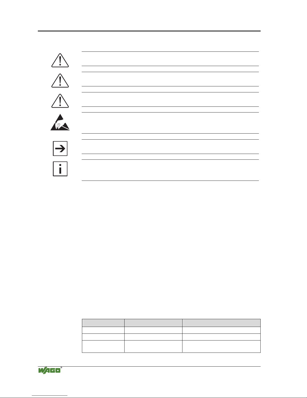
1.2 Symbols
Danger
Always abide by this information to protect persons from injury.
Warning
Always abide by this information to prevent damage to the device.
Attention
Marginal conditions must always be observed to ensure smooth operation.
ESD (Electrostatic Discharge)
Warning of damage to the components by electrostatic discharge. Observe
the precautionary measure for handling components at risk.
Note
Routines or advice for efficient use of the device and software optimization.
More information
References on additional literature, manuals, data sheets and INTERNET
pages
1.3 Font Conventions
Italic
Names of path and files are marked italic
i.e.: C:\programs\WAGO-IO-CHECK
Italic
Menu items are marked as bold italic
i.e.: Save
\
A backslash between two names marks a sequence of
menu items
i.e.: File\New
END
Press buttons are marked as bold with small capitals
i.e.: E
NTER
< >
Keys are marked bold within angle brackets
i.e.: <F5>
Courier
Program code is printed with the font Courier.
i.e.: END_VAR
1.4 Number Notation
Number Code Example Note
Decimal 100 normal notation
Hexadecimal 0x64 C notation
Binary '100'
'0110.0100'
Within ',
Nibble separated with dots
Page 7
Important Comments • 3
Safety Notes
WAGO-I/O-SYSTEM 750
ETHERNET TCP/IP
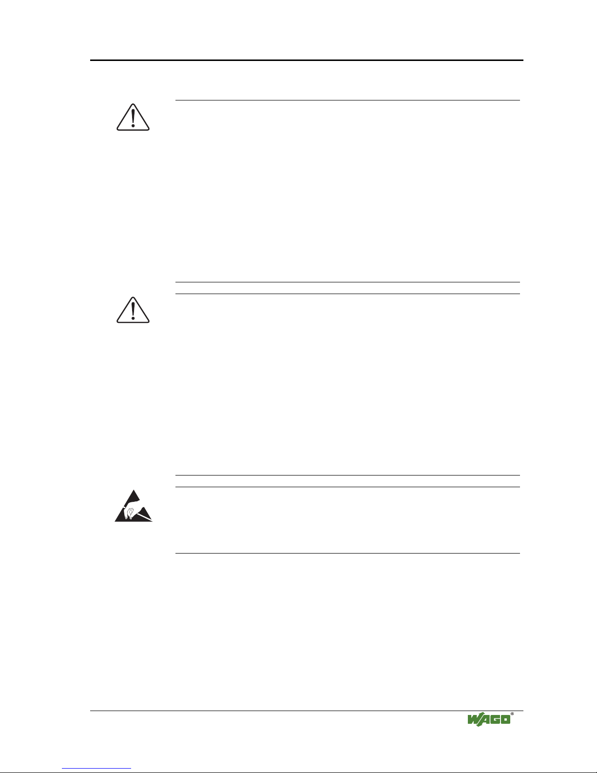
1.5 Safety Notes
Attention
Switch off the system prior to working on bus modules!
In the event of deformed contacts, the module in question is to be replaced, as
its functionality can no longer be ensured on a long-term basis.
The components are not resistant against materials having seeping and
insulating properties. Belonging to this group of materials is: e.g. aerosols,
silicones, triglycerides (found in some hand creams).
If it cannot be ruled out that these materials appear in the component
environment, then additional measures are to be taken:
- installation of the components into an appropriate enclosure
- handling of the components only with clean tools and materials.
Attention
Cleaning of soiled contacts may only be done with ethyl alcohol and leather
cloths. Thereby, the ESD information is to be regarded.
Do not use any contact spray. The spray may impair the functioning of the
contact area.
The WAGO-I/O-SYSTEM 750 and its components are an open system. It
must only be assembled in housings, cabinets or in electrical operation
rooms. Access must only be given via a key or tool to authorized qualified
personnel.
The relevant valid and applicable standards and guidelines concerning the
installation of switch boxes are to be observed.
ESD (Electrostatic Discharge)
The modules are equipped with electronic components that may be destroyed
by electrostatic discharge. When handling the modules, ensure that the
environment (persons, workplace and packing) is well grounded. Avoid
touching conductive components, e.g. gold contacts.
Page 8
4 • Important Comments
Scope
WAGO-I/O-SYSTEM 750
ETHERNET TCP/IP
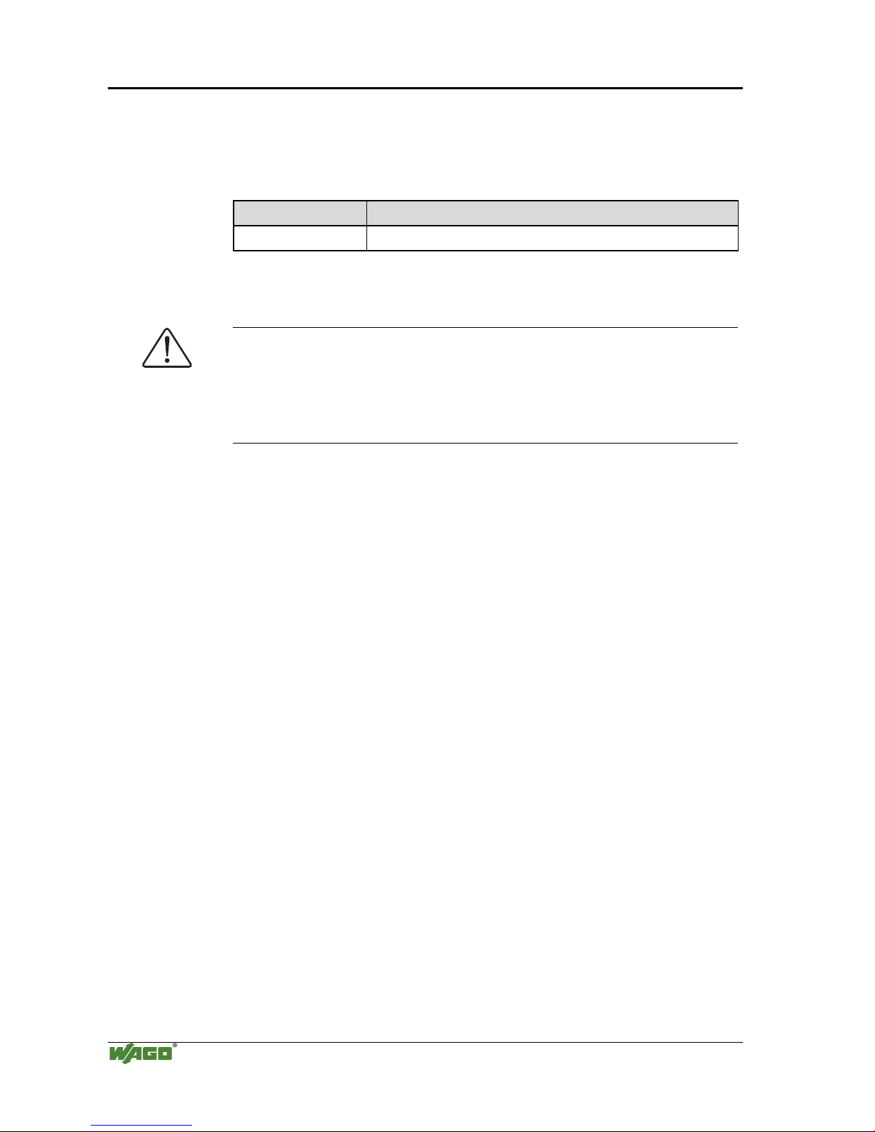
1.6 Scope
This manual describes the field bus independent WAGO-I/O-SYSTEM 750
with the programmable fieldbus controller for ETHERNET 10/100 MBit/s.
Item.-No. Description
750-841 Prog. Fieldbus Controller EtherNet 10/100 MBit/s
1.7 Important Comments for Starting up
Attention
For the start-up of the controller 750-841 important notes are to be
considered, because it strongly differentiates in some points of starting up the
controller 750-842.
Read for this the chapter: 3.1.7 „Starting up an ETHERNET TCP/IP fieldbus
node“.
1.8 Abbreviation
AI
Analog Input
AO
Analog Output
DI
Digital Input
DO
Digital Output
I/O
Input/Output
ID
Identifier
PFC
Programmable Fieldbus Controller
Page 9
The WAGO-I/O-SYSTEM 750 • 5
System Description
WAGO-I/O-SYSTEM 750
ETHERNET TCP/IP
2 The WAGO-I/O-SYSTEM 750
2.1 System Description
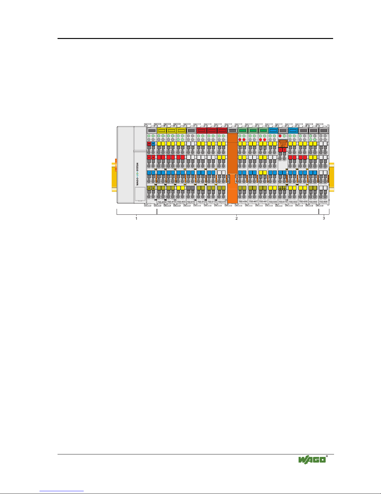
The WAGO-I/O-SYSTEM 750 is a modular, fieldbus independent I/O system.
It is comprised of a fieldbus coupler/controller (1) and up to 64 connected
fieldbus modules (2) for any type of signal. Together, these make up the
fieldbus node. The end module (3) completes the node.
Fig. 2-1: Fieldbus node
g0xxx00x
Couplers / controllers for fieldbus systems such as PROFIBUS, INTERBUS,
ETHERNET TCP/IP, CAN (CANopen, DeviceNet, CAL), MODBUS, LON
and others are available.
The coupler / controller contains the fieldbus interface, electronics and a
power supply terminal. The fieldbus interface forms the physical interface to
the relevant fieldbus. The electronics process the data of the bus modules and
make it available for the fieldbus communication. The 24 V system supply and
the 24 V field supply are fed in via the integrated power supply terminal.
The fieldbus coupler communicates via the relevant fieldbus. The
programmable fieldbus controller (PFC) enables the implementation of
additional PLC functions. Programming is done with the WAGO-I/O-PRO 32
in accordance with IEC 61131-3.
Bus modules for diverse digital and analog I/O functions as well as special
functions can be connected to the coupler / controller. The communication
between the coupler/controller and the bus modules is carried out via an
internal bus.
The WAGO-I/O-SYSTEM 750 has a clear port level with LEDs for status
indication, insertable mini WSB markers and pullout group marker carriers.
The 3-wire technology supplemented by a ground wire connection allows for
direct sensor/actuator wiring.
Page 10
6 • The WAGO-I/O-SYSTEM 750
Technical Data
WAGO-I/O-SYSTEM 750
ETHERNET TCP/IP
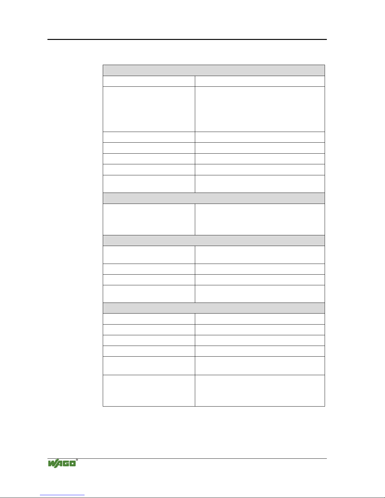
2.2 Technical Data
Mechanic
Material Polycarbonate, Polyamide 6.6
Dimensions
- Coupler / Controller
- I/O module, single
- I/O module, double
- 51 mm x 65* mm x 100 mm
- 12 mm x 64* mm x 100 mm
- 24 mm x 64* mm x 100 mm
* from upper edge of DIN 35 rail
Installation on DIN 35 with interlock
modular by double featherkey-dovetail
Mounting position any position
Length of entire node
≤ 831 mm
Marking marking label type 247 and 248
paper marking label 8 x 47 mm
Wire range
Wire range CAGE CLAMP® Connection
0,08 mm² ... 2.5 mm²
AWG 28-14
8 – 9 mm Stripped length
Contacts
Power jumpers contacts blade/spring contact
self-cleaning
Current via power contacts
max
10 A
Voltage drop at I
max
< 1 V/64 modules
Data contacts slide contact, hard gold plated
1,5µm, self-cleaning
Climatic environmental conditions
Operating temperature 0 °C ... 55 °C
Storage temperature -20 °C ... +85 °C
Relative humidity 5% to 95 % without condensation
Resistance to harmful substances acc. To IEC 60068-2-42 and IEC 60068-2-43
Maximum pollutant concentration at
relative humidity < 75%
SO
2
≤ 25 ppm
H
2
S ≤ 10 ppm
Special conditions Ensure that additional measures for components are
taken, which are used in an environment involving:
– dust, caustic vapors or gasses
– ionization radiation.
Page 11
The WAGO-I/O-SYSTEM 750 • 7
Technical Data
WAGO-I/O-SYSTEM 750
ETHERNET TCP/IP
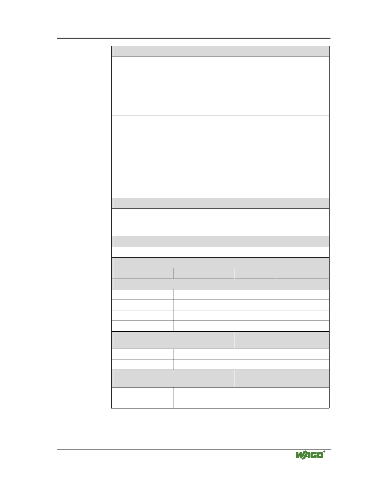
Mechanical strength
Vibration resistance acc. to IEC 60068-2-6
Comment to the vibration restistance:
a) Type of oscillation:
sweep with a rate of change of 1 octave per minute
10 Hz ≤ f < 57 Hz, const. Amplitude 0,075 mm
57 Hz ≤ f < 150 Hz, const. Acceleration 1 g
b) Period of oscillation:
10 sweep per axis in each of the 3 vertical axes
Shock resistance acc. to IEC 60068-2-27
Comment to the shock restistance:
a) Type of impulse: half sinusoidal
b) Intensity of impulse:
15 g peak value, 11 ms maintenance time
c) Route of impulse:
3 impulses in each pos. And neg. direction of the
3 vertical axes of the test object, this means
18 impulses in all
Free fall acc. to IEC 60068-2-32
≤ 1m (module in original packing)
Safe electrical isolation
Air and creepage distance acc. to IEC 60664-1
Degree of pollution
acc. To IEC 61131-2
2
Degree of protection
Degree of protection IP 20
Electromagnetic compatibility*
Directive Test values Strength class Evaluation criteria
Immunity to interference acc. to EN 50082-2 (96)
EN 61000-4-2 4kV/8kV (2/4) B
EN 61000-4-3 10V/m 80% AM (3) A
EN 61000-4-4 2kV (3/4) B
EN 61000-4-6 10V/m 80% AM (3) A
Emission of interference acc. to
EN 50081-2 (94)
Measuring
distance
Class
EN 55011 30 dBµV/m (30m) A
37 dBµV/m
Emission of interference acc. to
EN 50081-1 (93)
Measuring
distance
Class
EN 55022 30 dBµV/m (10m) B
37 dBµV/m
* Exception: 750-630, 750-631
Page 12
8 • The WAGO-I/O-SYSTEM 750
Technical Data
WAGO-I/O-SYSTEM 750
ETHERNET TCP/IP
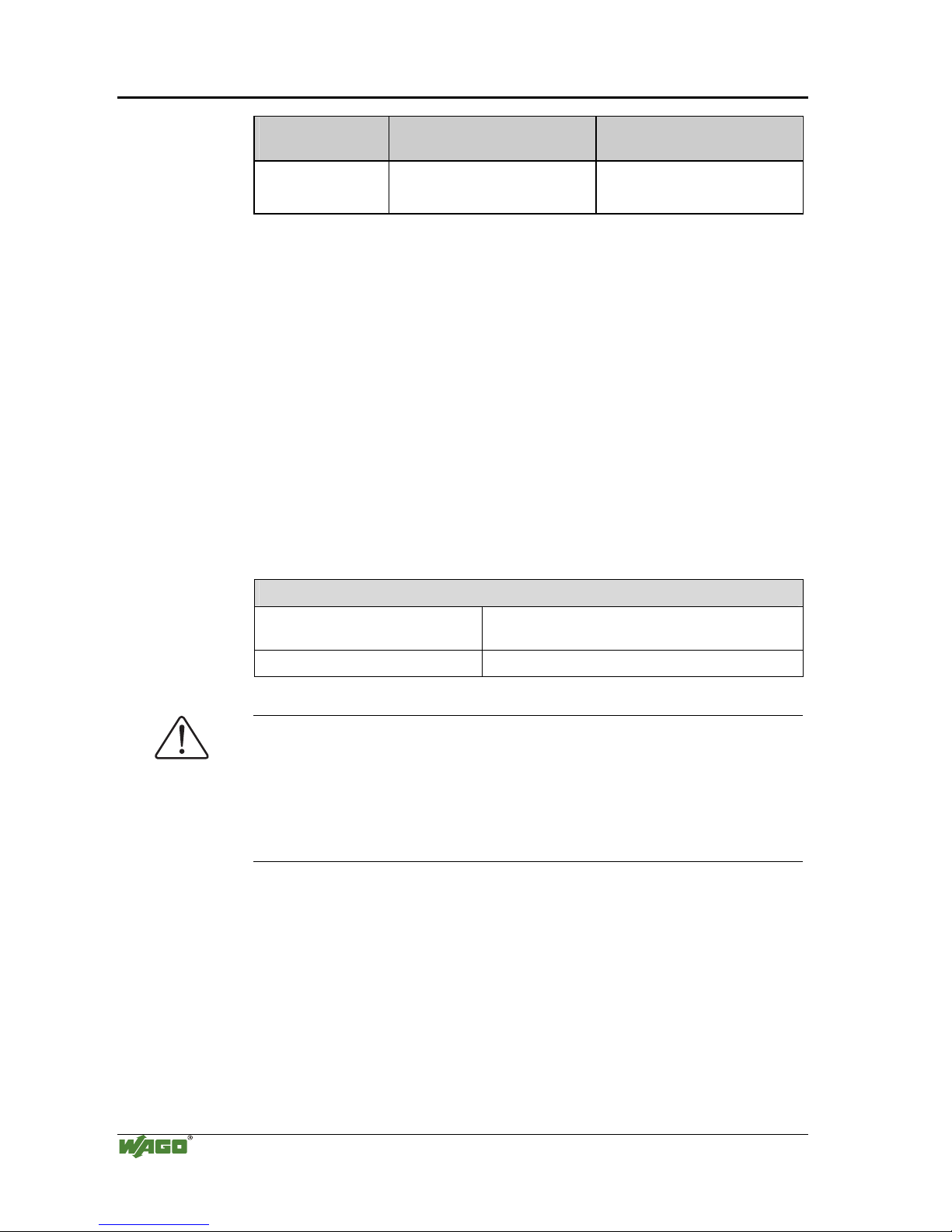
Range of
application
Required specification
emission of interference
Required specification
immunity to interference
Industrial areas EN 50081-2 : 1993 EN 50082-2 : 1996
Residential areas EN 50081-1 : 1993*) EN 50082-1 : 1992
*)
The system meets the requirements on emission of interference in residential areas with
the fieldbus coupler/controller for:
ETHERNET
LonWorks
CANopen
DeviceNet
MODBUS
750-342/-841/-842
750-319/-819
750-337/-837
750-306/-806
750-312/-314/ -315/ -316
750-812/-814/ -815/ -816
With a special permit, the system can also be implemented with other fieldbus
couplers/controllers in residential areas (housing, commercial and business areas, smallscale enterprises). The special permit can be obtained from an authority or inspection
office. In Germany, the Federal Office for Post and Telecommunications and its branch
offices issues the permit.
It is possible to use other field bus couplers / controllers under certain boundary
conditions. Please contact WAGO Kontakttechnik GmbH.
Maximum power dissipation of the components
Bus modules 0.8 W / bus terminal (total power dissipation,
system/field)
Fieldbus coupler / controller 2.0 W / coupler / controller
Warning
The power dissipation of all installed components must not exceed the
maximum conductible power of the housing (cabinet).
When dimensioning the housing, care is to be taken that even under high
external temperatures, the temperature inside the housing does not exceed the
permissible ambient temperature of 55 °C.
Page 13
The WAGO-I/O-SYSTEM 750 • 9
Manufacturing Number
WAGO-I/O-SYSTEM 750
ETHERNET TCP/IP
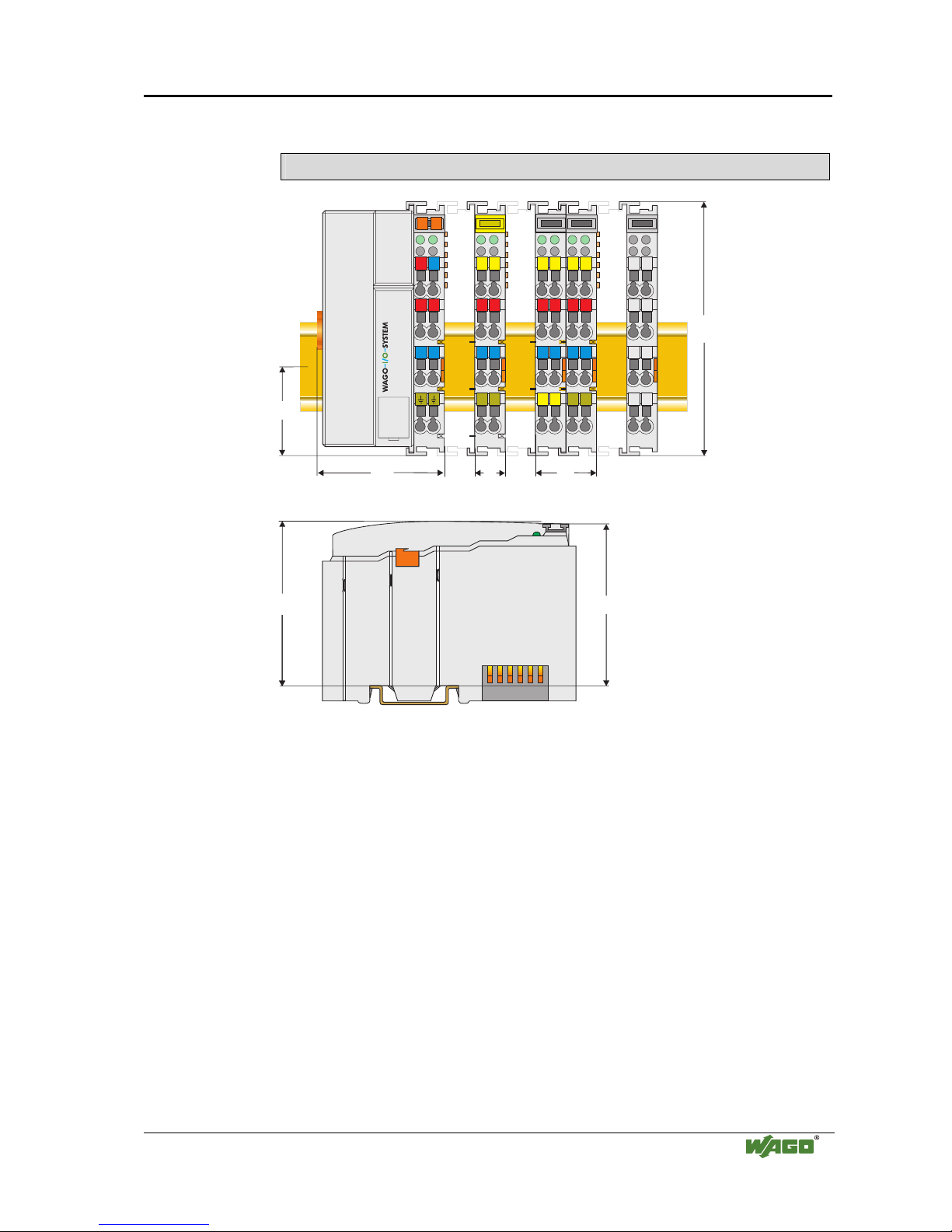
Dimensions
51
24V 0V
+
+
-
-
01
02
C
D
B
A
C
D
B
A
C
D
B
A
C
D
B
A
C
D
B
A
100
12
24
64
35
65
Side view
Dimensions in mm
Fig. 2-2: Dimensions
g01xx05e
2.3 Manufacturing Number
The manufacturing number indicates the delivery status directly after
production.
This number is part of the lateral marking on the component.
In addition, starting from calender week 43/2000 the manufacturing number is
also printed on the cover of the configuration and programming interface of
the fieldbus coupler or controller.
Page 14
10 • The WAGO-I/O-SYSTEM 750
Component Update
WAGO-I/O-SYSTEM 750
ETHERNET TCP/IP
Hansastr. 27
D-32423 Minden
ITEM-NO.:750-333
PROFIBUS DP 12 MBd /DPV1
0V
Power Supply
Electronic
PATENTS PENDING
II 3 GD
DEMKO 02 ATEX132273 X
EEx nA II T4
24V DC
AWG 28-14
55°C max ambient
LISTED 22ZAAND 22XM
72072
0103000203-B000000
Hansastr. 27
D-32423 Minden
ITEM-NO.:750-333
PROFIBUS DP 12 MBd /DPV1
0V
Power Supply
Electronic
PATENTS PENDING
II 3 GD
DEMKO 02 ATEX132273 X
EEx nA II T4
24V DC
AWG 28-14
55°C max ambient
LISTED 22ZAAND 22XM
72072
0103000203-B000000
1
0
3
0
0
0
2
0
0
3
DS
NO
SW
HW
GL
FWL
Power Supply
Field
24 V
+
-
-B000000
Manufacturing Number
Calendar
week
Year Software
version
Hardware
version
Firmware-loader
version
Internal
Number
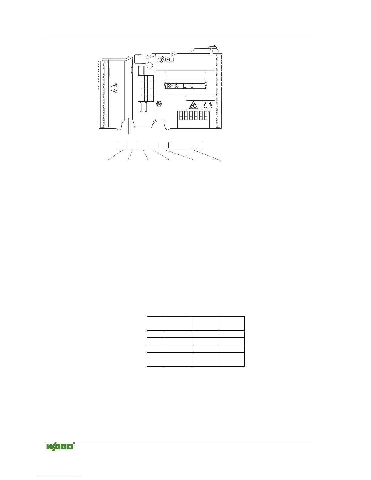
Fig. 2-3: Example: Manufacturing Number of a PROFIBUS fieldbus coupler 750-333
g01xx15e
The manufacturing number consists of the production week and year, the
software version (if available), the hardware version of the component, the
firmware loader (if available) and further internal information for
WAGO Kontakttechnik GmbH.
2.4 Component Update
For the case of an Update of one component, the lateral marking on each
component contains a prepared matrix.
This matrix makes columns available for altogether three updates to the entry
of the current update data, like production order number (NO; starting from
calendar week 13/2004), update date (DS), software version (SW), hardware
version (HW) and the firmware loader version (FWL, if available).
Update Matrix
Current Version data for: 1. Update 2. Update 3. Update
Production Order
Number
NO
<- Only starting from
Calendar week 13/2004
Datestamp
DS
Software index
SW
Hardware index
HW
Firmware loader
index
FWL
<- Only for coupler/controller
If the update of a component took place, the current version data are registered
into the columns of the matrix.
Additionally with the update of a fieldbus coupler or controller also the cover
of the configuration and programming interface of the coupler or controller is
printed on with the current manufacturing and production order number.
The original manufacturing data on the housing of the component remain
thereby.
Page 15
The WAGO-I/O-SYSTEM 750 • 11
Storage, Assembly and Transport
WAGO-I/O-SYSTEM 750
ETHERNET TCP/IP
2.5 Storage, Assembly and Transport
Wherever possible, the components are to be stored in their original
packaging. Likewise, the original packaging provides optimal protection
during transport.
When assembling or repacking the components, the contacts must not be
soiled or damaged. The components must be stored and transported in
appropriate containers/packaging. Thereby, the ESD information is to be
regarded.
Statically shielded transport bags with metal coatings are to be used for the
transport of open components for which soiling with amine, amide and
silicone has been ruled out, e.g. 3M 1900E.
2.6 Mechanical Setup
2.6.1 Installation Position
Along with horizontal and vertical installation, all other installation positions
are allowed.
Attention
In the case of vertical assembly, an end stop has to be mounted as an
additional safeguard against slipping.
WAGO item 249-116 End stop for DIN 35 rail, 6 mm wide
WAGO item 249-117 End stop for DIN 35 rail, 10 mm wide
2.6.2 Total Expansion
The maximum total expansion of a node is calculated as follows:
Quantity Width Components
1 51 mm coupler / controller
64 12 mm bus modules
- inputs / outputs
- power supply modules
- etc.
1 12 mm end module
sum 831 mm
Warning
The maximal total expansion of a node must not exceed 831 mm
Page 16

12 • The WAGO-I/O-SYSTEM 750
Mechanical Setup
WAGO-I/O-SYSTEM 750
ETHERNET TCP/IP
2.6.3 Assembly onto Carrier Rail
2.6.3.1 Carrier rail properties
All system components can be snapped directly onto a carrier rail in
accordance with the European standard EN 50022 (DIN 35).
Warning
WAGO supplies standardized carrier rails that are optimal for use with the
I/O system. If other carrier rails are used, then a technical inspection and
approval of the rail by WAGO Kontakttechnik GmbH should take place.
Carrier rails have different mechanical and electrical properties. For the
optimal system setup on a carrier rail, certain guidelines must be observed:
• The material must be non-corrosive.
• Most components have a contact to the carrier rail to ground electro-
magnetic disturbances. In order to avoid corrosion, this tin-plated carrier
rail contact must not form a galvanic cell with the material of the carrier
rail which generates a differential voltage above 0.5 V (saline solution of
0.3% at 20°C) .
• The carrier rail must optimally support the EMC measures integrated into
the system and the shielding of the bus module connections.
• A sufficiently stable carrier rail should be selected and, if necessary,
several mounting points (every 20 cm) should be used in order to prevent
bending and twisting (torsion).
• The geometry of the carrier rail must not be altered in order to secure the
safe hold of the components. In particular, when shortening or mounting
the carrier rail, it must not be crushed or bent.
• The base of the I/O components extends into the profile of the carrier rail.
For carrier rails with a height of 7.5 mm, mounting points are to be riveted
under the node in the carrier rail (slotted head captive screws or blind
rivets).
Page 17
The WAGO-I/O-SYSTEM 750 • 13
Mechanical Setup
WAGO-I/O-SYSTEM 750
ETHERNET TCP/IP
2.6.3.2 WAGO DIN Rail
WAGO carrier rails meet the electrical and mechanical requirements.
Item Number Description
210-113 /-112 35 x 7.5; 1 mm; steel yellow chromated; slotted/unslotted
210-114 /-197 35 x 15; 1.5 mm; steel yellow chromated; slotted/unslotted
210-118 35 x 15; 2.3 mm; steel yellow chromated; unslotted
210-198 35 x 15; 2.3 mm; copper; unslotted
210-196 35 x 7.5; 1 mm; aluminum; unslotted
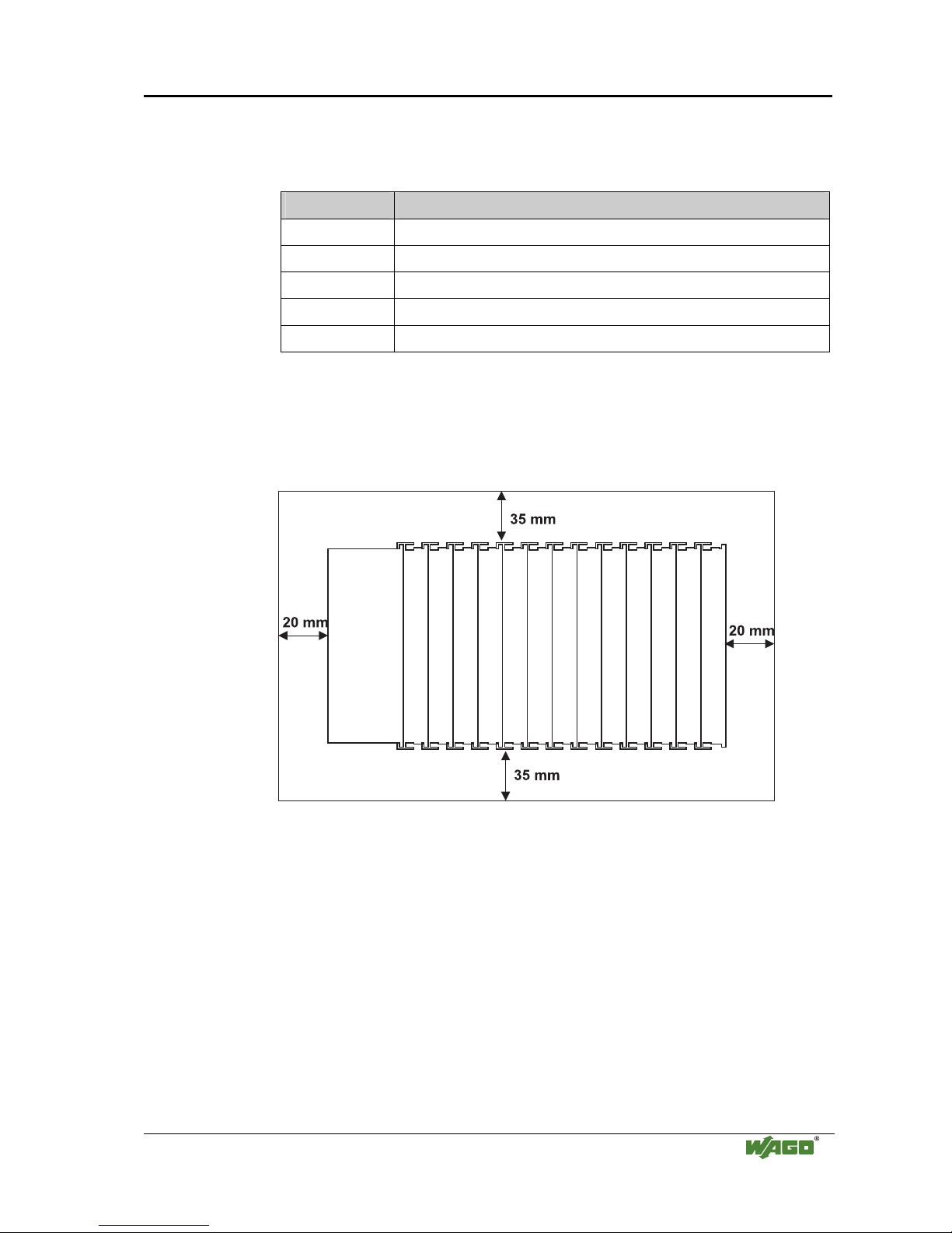
2.6.4 Spacing
The spacing between adjacent components, cable conduits, casing and frame
sides must be maintained for the complete field bus node.
Fig. 2-4: Spacing
g01xx13x
The spacing creates room for heat transfer, installation or wiring. The spacing
to cable conduits also prevents conducted electromagnetic interferences from
influencing the operation.
Page 18
14 • The WAGO-I/O-SYSTEM 750
Mechanical Setup
WAGO-I/O-SYSTEM 750
ETHERNET TCP/IP
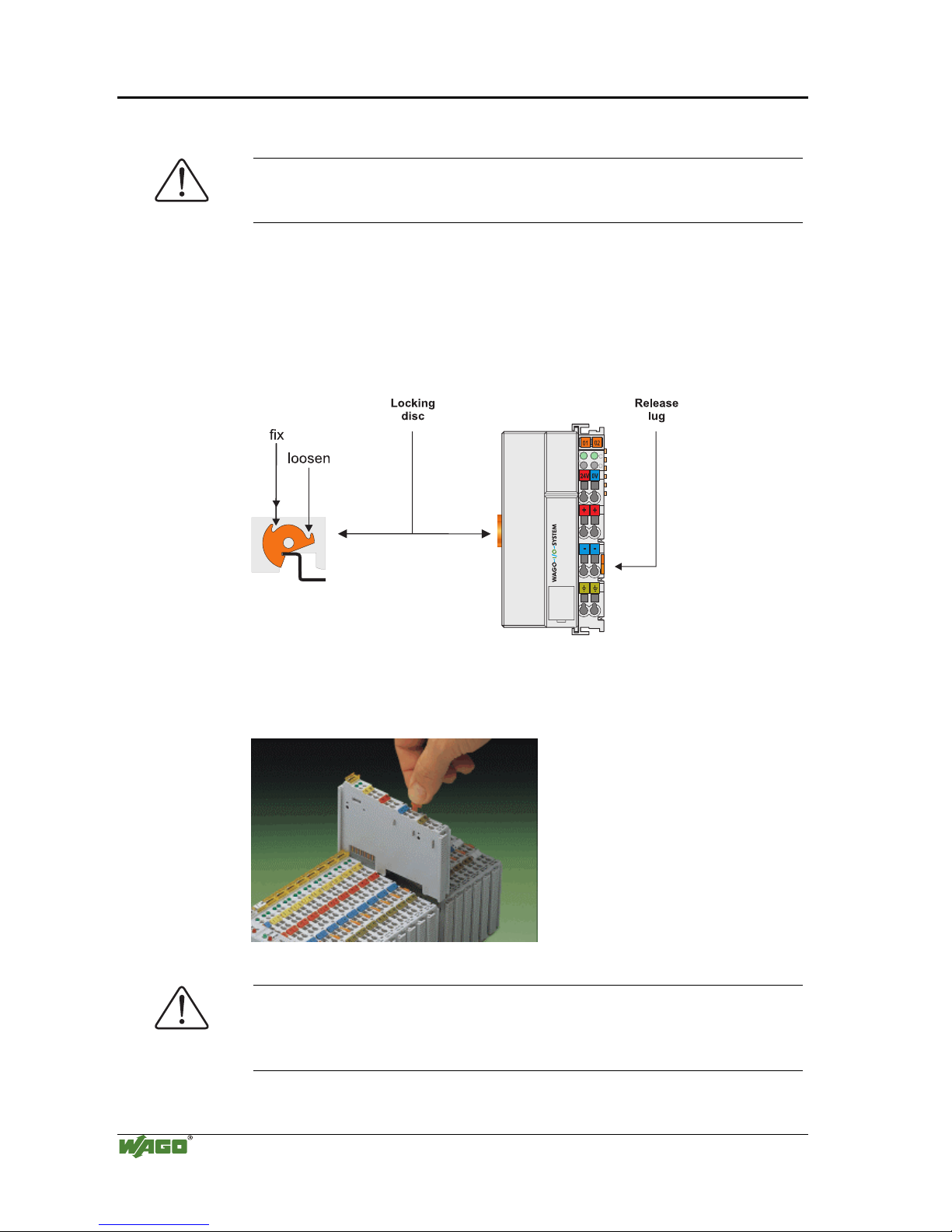
2.6.5 Plugging and Removal of the Components
Warning
Before work is done on the components, the voltage supply must be turned
off.
In order to safeguard the coupler/controller from jamming, it should be fixed
onto the carrier rail with the locking disc To do so, push on the upper groove
of the locking disc using a screwdriver.
To pull out the fieldbus coupler/controller, release the locking disc by pressing
on the bottom groove with a screwdriver and then pulling the orange colored
unlocking lug.
Fig. 2-5: Coupler/Controller and unlocking lug
g01xx12e
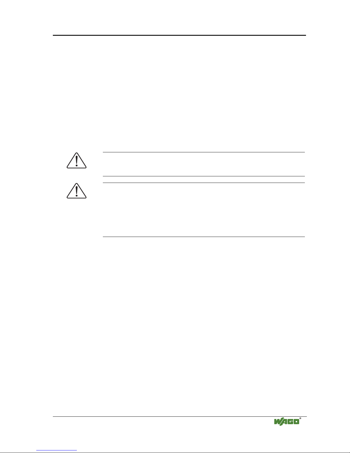
It is also possible to release an individual I/O module from the unit by pulling
an unlocking lug.
Fig. 2-6: removing bus terminal
p0xxx01x
Danger
Ensure that an interruption of the PE will not result in a condition which
could endanger a person or equipment!
For planning the ring feeding of the ground wire, please see chapter 2.6.3.
Page 19
The WAGO-I/O-SYSTEM 750 • 15
Mechanical Setup
WAGO-I/O-SYSTEM 750
ETHERNET TCP/IP
2.6.6 Assembly Sequence
All system components can be snapped directly on a carrier rail in accordance
with the European standard EN 50022 (DIN 35).
The reliable positioning and connection is made using a tongue and groove
system. Due to the automatic locking, the individual components are securely
seated on the rail after installing.
Starting with the coupler/controller, the bus modules are assembled adjacent
to each other according to the project planning. Errors in the planning of the
node in terms of the potential groups (connection via the power contacts) are
recognized, as the bus modules with power contacts (male contacts) cannot be
linked to bus modules with fewer power contacts.
Attention
Always link the bus modules with the coupler / controller, and always plug
from above.
Warning
Never plug bus modules from the direction of the end terminal. A ground
wire power contact, which is inserted into a terminal without contacts, e.g. a
4-channel digital input module, has a decreased air and creepage distance to
the neighboring contact in the example DI4.
Always terminate the fieldbus node with an end module (750-600).
Page 20
16 • The WAGO-I/O-SYSTEM 750
Mechanical Setup
WAGO-I/O-SYSTEM 750
ETHERNET TCP/IP
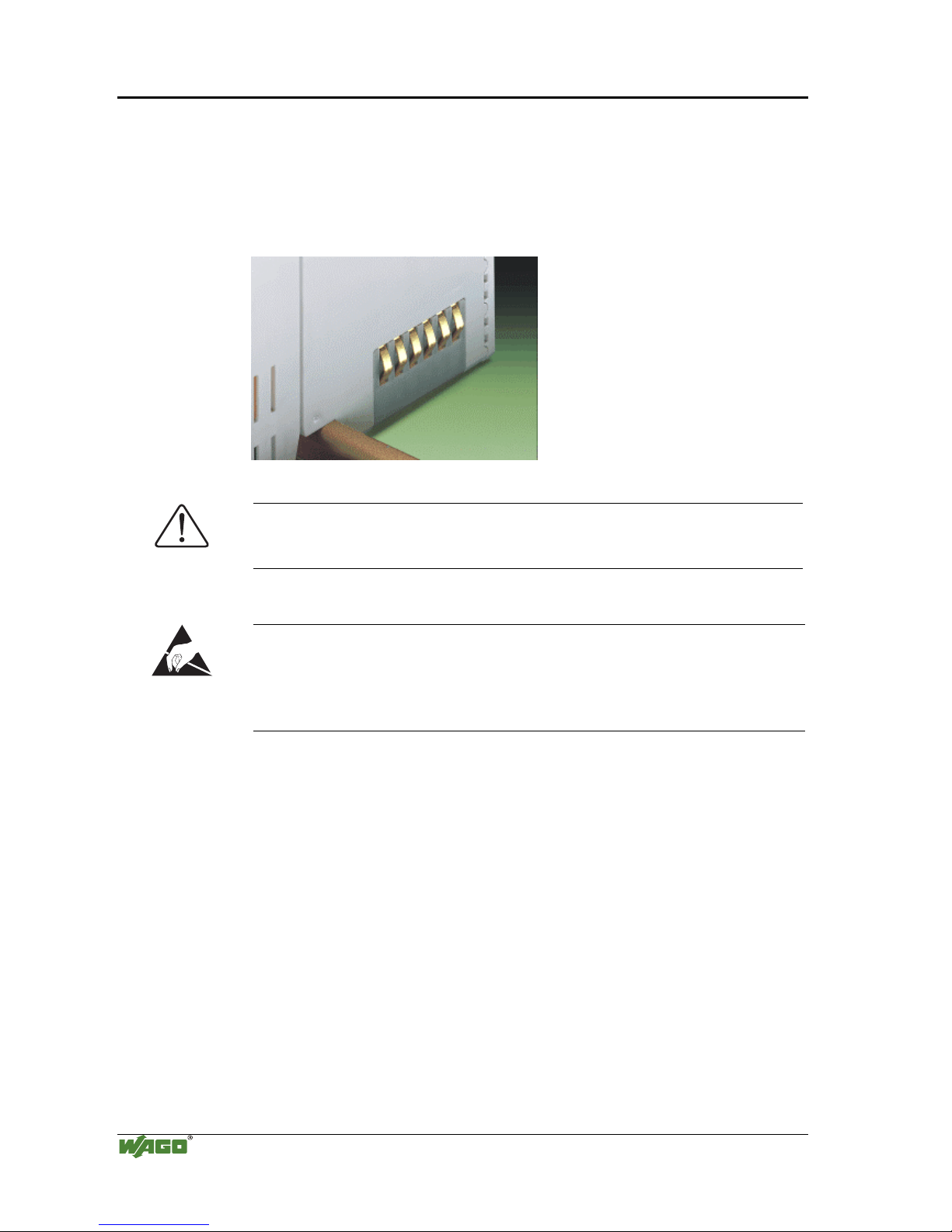
2.6.7 Internal Bus / Data Contacts
Communication between the coupler/controller and the bus modules as well as
the system supply of the bus modules is carried out via the internal bus. It is
comprised of 6 data contacts, which are available as self-cleaning gold spring
contacts.
Fig. 2-7: Data contacts
p0xxx07x
Warning
Do not touch the gold spring contacts on the I/O modules in order to avoid
soiling or scratching!
ESD (Electrostatic Discharge)
The modules are equipped with electronic components that may be destroyed
by electrostatic discharge. When handling the modules, ensure that the
environment (persons, workplace and packing) is well grounded. Avoid
touching conductive components, e.g. gold contacts.
Page 21
The WAGO-I/O-SYSTEM 750 • 17
Mechanical Setup
WAGO-I/O-SYSTEM 750
ETHERNET TCP/IP
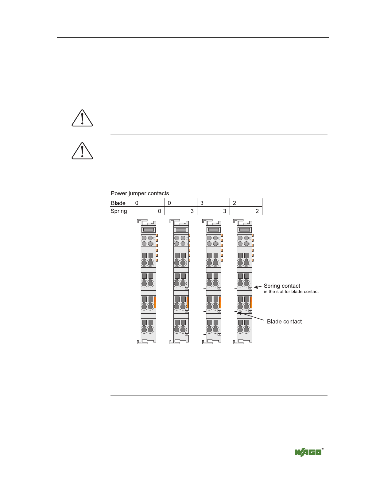
2.6.8 Power Contacts
Self-cleaning power contacts , are situated on the side of the components
which further conduct the supply voltage for the field side. These contacts
come as touchproof spring contacts on the right side of the coupler/controller
and the bus module. As fitting counterparts the module has male contacts on
the left side.
Danger
The power contacts are sharp-edged. Handle the module carefully to prevent
injury.
Attention
Please take into consideration that some bus modules have no or only a few
power jumper contacts. The design of some modules does not allow them to
be physically assembled in rows, as the grooves for the male contacts are
closed at the top.
Fig. 2-8: Example for the arrangement of power contacts
g0xxx05e
Recommendation
With the WAGO ProServe® Software smartDESIGNER, the assembly of a
fieldbus node can be configured. The configuration can be tested via the
integrated accuracy check.
Page 22
18 • The WAGO-I/O-SYSTEM 750
Mechanical Setup
WAGO-I/O-SYSTEM 750
ETHERNET TCP/IP
2.6.9 Wire connection
All components have CAGE CLAMP® connections.
The WAGO CAGE CLAMP® connection is appropriate for solid, stranded
and fine–stranded conductors. Each clamping unit accommodates one
conductor.
Fig. 2-9: CAGE CLAMP® Connection
g0xxx08x
The operating tool is inserted into the opening above the connection. This
opens the CAGE CLAMP®. Subsequently the conductor can be inserted into
the opening. After removing the operating tool, the conductor is safely
clamped.
More than one conductor per connection is not permissible. If several
conductors have to be made at one connection point, then they should be made
away from the connection point using WAGO Terminal Blocks. The terminal
blocks may be jumpered together and a single wire brought back to the I/O
module connection point.
Attention
If it is unavoidable to jointly connect 2 conductors, then a ferrule must be
used to join the wires together.
Ferrule:
Length 8 mm
Nominal cross section
max.
1 mm2 for 2 conductors with 0.5 mm2
each
WAGO Product 216-103
or products with comparable properties
Page 23
The WAGO-I/O-SYSTEM 750 • 19
Power Supply
WAGO-I/O-SYSTEM 750
ETHERNET TCP/IP
2.7 Power Supply
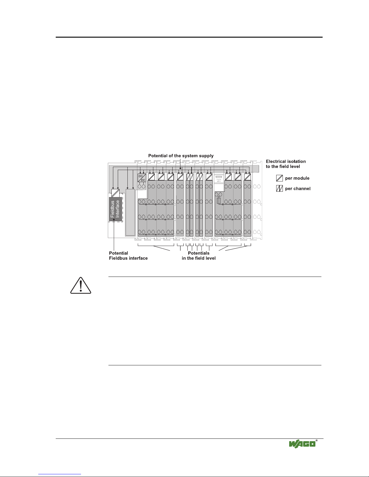
2.7.1 Isolation
Within the fieldbus node, there are three electrically isolated potentials.
• Operational voltage for the fieldbus interface.
• Electronics of the couplers / controllers and the bus modules (internal bus).
• All bus modules have an electrical isolation between the electronics
(internal bus, logic) and the field electronics. Some digital and analog
input modules have each channel electrically isolated, please see catalog.
Fig. 2-10: Isolation
g0xxx01e
Attention
The ground wire connection must be present in each group. In order that all
protective conductor functions are maintained under all circumstances, it is
recommended that a ground wire be connected at the beginning and end of a
potential group. (ring format, please see chapter "2.8.3"). Thus, if a bus
module comes loose from a composite during servicing, then the protective
conductor connection is still guaranteed for all connected field devices.
When using a joint power supply unit for the 24 V system supply and the
24 V field supply, the electrical isolation between the internal bus and the
field level is eliminated for the potential group.
Page 24
20 • The WAGO-I/O-SYSTEM 750
Power Supply
WAGO-I/O-SYSTEM 750
ETHERNET TCP/IP
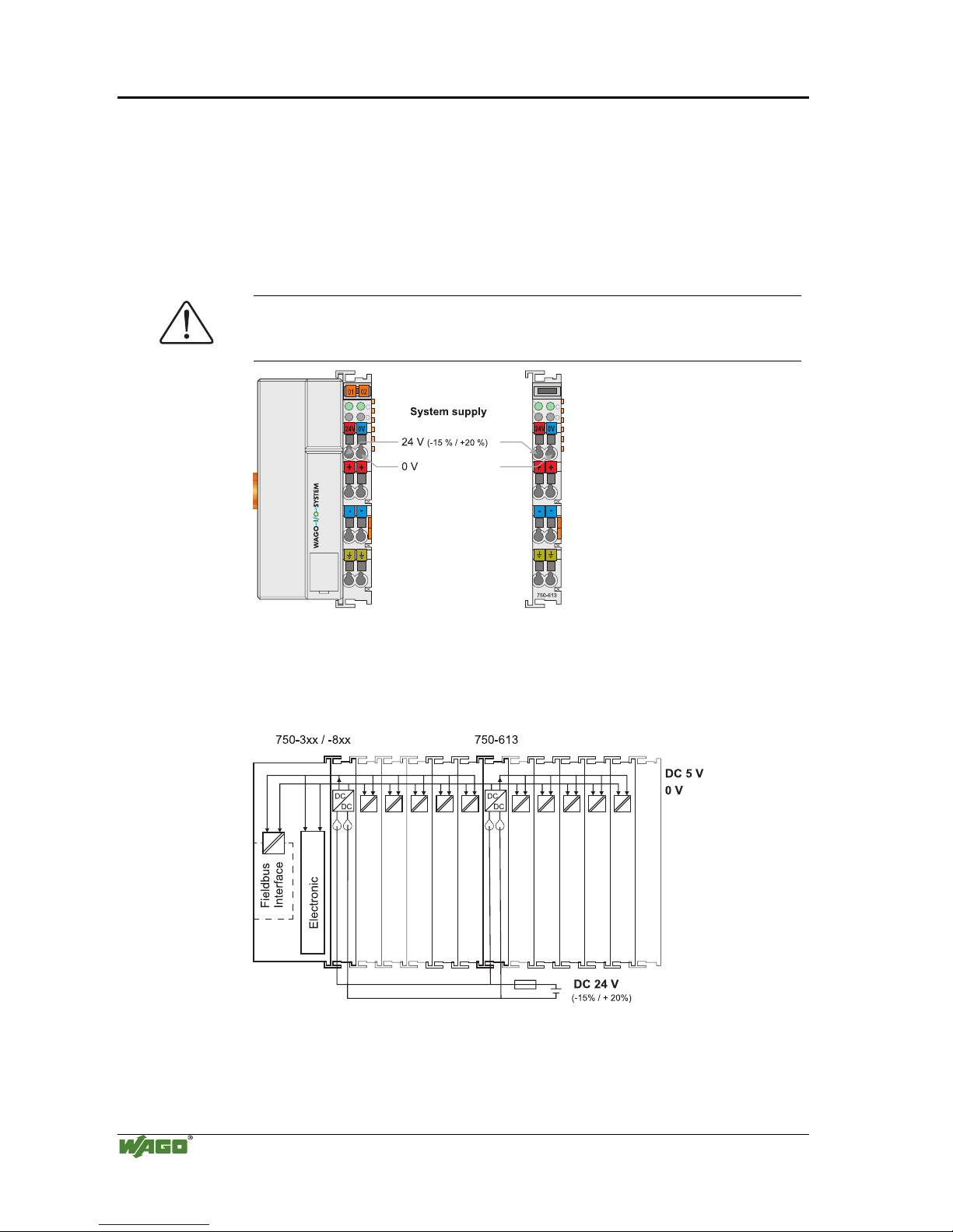
2.7.2 System Supply
2.7.2.1 Connection
The WAGO-I/O-SYSTEM 750 requires a 24 V direct current system supply
(-15% or +20 %). The power supply is provided via the coupler / controller
and, if necessary, in addition via the internal system supply modules
(750-613). The voltage supply is reverse voltage protected.
Attention
The use of an incorrect supply voltage or frequency can cause severe damage
to the component.
Fig. 2-11: System Supply
g0xxx02e
The direct current supplies all internal system components, e.g.
coupler/controller electronics, fieldbus interface and bus modules via the
internal bus (5 V system voltage). The 5 V system voltage is electrically
connected to the 24 V system supply.
Fig. 2-12: System Voltage g0xxx06e
Page 25
The WAGO-I/O-SYSTEM 750 • 21
Power Supply
WAGO-I/O-SYSTEM 750
ETHERNET TCP/IP
Attention
Resetting the system by switching on and off the system supply, must take
place simultaneously for all supply modules (coupler / controller and
750-613).
2.7.2.2 Alignment
Recommendation
A stable network supply cannot be taken for granted always and everywhere.
Therefore, regulated power supply units should be used in order to guarantee
the quality of the supply voltage.
The supply capacity of the coupler/controller or the internal system supply
module (750-613) can be taken from the technical data of the components.
Internal current consumption*)
Current consumption via system voltage:
5 V for electronics of the bus modules and coupler /
controller
Residual current for bus
terminals*)
Available current for the bus modules. Provided by
the bus power supply unit. See coupler / controller
and internal system supply module (750-613)
*) cf. catalogue W4 Volume 3, manuals or Internet
Example
Coupler 750-301:
internal current consumption:350 mA at 5V
residual current for
bus modules : 1650 mA at 5V
sum I(5V)
total
: 2000 mA at 5V
The internal current consumption is indicated in the technical data for each
bus terminal. In order to determine the overall requirement, add together the
values of all bus modules in the node.
Attention
If the sum of the internal current consumption exceeds the residual current
for bus modules, then an internal system supply module (750-613) must be
placed before the module where the permissible residual current was
exceeded.
Example:
A node with a PROFIBUS Coupler 750-333 consists of 20 relay
modules (750-517) and 10 digital input modules (750-405).
Current consumption:
20* 90 mA = 1800 mA
10* 2 mA = 20 mA
Sum 1820 mA
The coupler can provide 1650 mA for the bus modules. Consequently,
an internal system supply module (750-613), e.g. in the middle of the
node, should be added.
Page 26

22 • The WAGO-I/O-SYSTEM 750
Power Supply
WAGO-I/O-SYSTEM 750
ETHERNET TCP/IP
Recommendation
With the WAGO ProServe® Software smartDESIGNER, the assembly of a
fieldbus node can be configured. The configuration can be tested via the
integrated accuracy check.
The maximum input current of the 24 V system supply is 500 mA. The exact
electrical consumption (I
(24 V)
) can be determined with the following formulas:
Coupler/Controller
I(5 V)
total
= Sum of all the internal current consumption of the connected
bus modules
+ internal current consumption coupler / controller
750-613
I(5 V)
total
= Sum of all the internal current consumption of the connected
bus modules
Input current I(24 V) =
5 V / 24 V * I(5 V)
total
/ η
η = 0.87 (at nominal load)
Note
If the electrical consumption of the power supply point for the 24 V-system
supply exceeds 500 mA, then the cause may be an improperly aligned node
or a defect.
During the test, all outputs, in particular those of the relay modules, must be
active.
Page 27
The WAGO-I/O-SYSTEM 750 • 23
Power Supply
WAGO-I/O-SYSTEM 750
ETHERNET TCP/IP
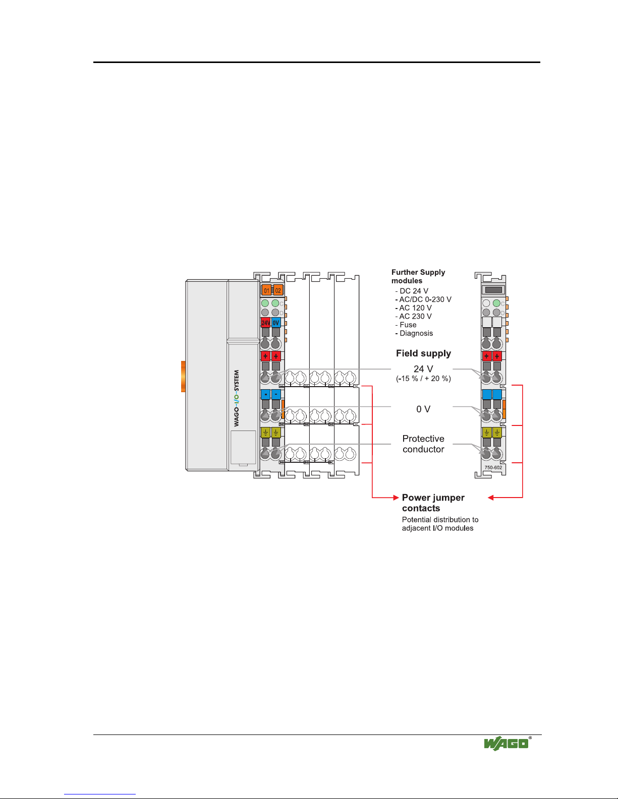
2.7.3 Field Supply
2.7.3.1 Connection
Sensors and actuators can be directly connected to the relevant channel of the
bus module in 1-/4 conductor connection technology. The bus module supplies
power to the sensors and actuators. The input and output drivers of some bus
modules require the field side supply voltage.
The coupler/controller provides field side power (DC 24V). In this case it is a
passive power supply without protection equipment.
Power supply modules are available for other potentials, e.g. AC 230 V.
Likewise, with the aid of the power supply modules, various potentials can be
set up. The connections are linked in pairs with a power contact.
Fig. 2-13: Field Supply (Sensor / Actuator)
g0xxx03e
The supply voltage for the field side is automatically passed to the next
module via the power jumper contacts when assembling the bus modules .
The current load of the power contacts must not exceed 10 A on a continual
basis. The current load capacity between two connection terminals is identical
to the load capacity of the connection wires.
By inserting an additional power supply module, the field supply via the
power contacts is disrupted. From there a new power supply occurs which
may also contain a new voltage potential.
Page 28
24 • The WAGO-I/O-SYSTEM 750
Power Supply
WAGO-I/O-SYSTEM 750
ETHERNET TCP/IP
Attention
Some bus modules have no or very few power contacts (depending on the I/O
function). Due to this, the passing through of the relevant potential is
disrupted. If a field supply is required for subsequent bus modules, then a
power supply module must be used.
Note the data sheets of the bus modules.
In the case of a node setup with different potentials, e.g. the alteration from
DC 24 V to AC 230V, a spacer module should be used. The optical
separation of the potentials acts as a warning to heed caution in the case of
wiring and maintenance works. Thus, the results of wiring errors can be
prevented.
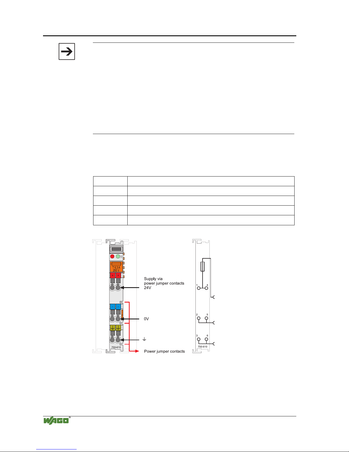
2.7.3.2 Fusing
Internal fusing of the field supply is possible for various field voltages via an
appropriate power supply module.
750-601 24 V DC, Supply / Fuse
750-609 230 V AC, Supply / Fuse
750-615 120 V AC, Supply / Fuse
750-610 24 V DC, Supply / Fuse / Diagnosis
750-611 230 V AC, Supply / Fuse / Diagnosis
Fig. 2-14: Supply module with fuse carrier (Example 750-610)
g0xxx09x
Page 29
The WAGO-I/O-SYSTEM 750 • 25
Power Supply
WAGO-I/O-SYSTEM 750
ETHERNET TCP/IP
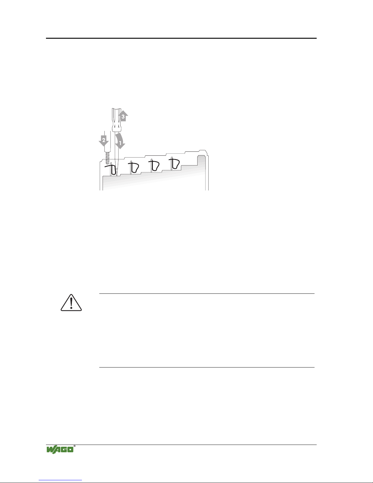
Warning
In the case of power supply modules with fuse holders, only fuses with a
maximum dissipation of 1.6 W (IEC 127) must be used.
For UL approved systems only use UL approved fuses.
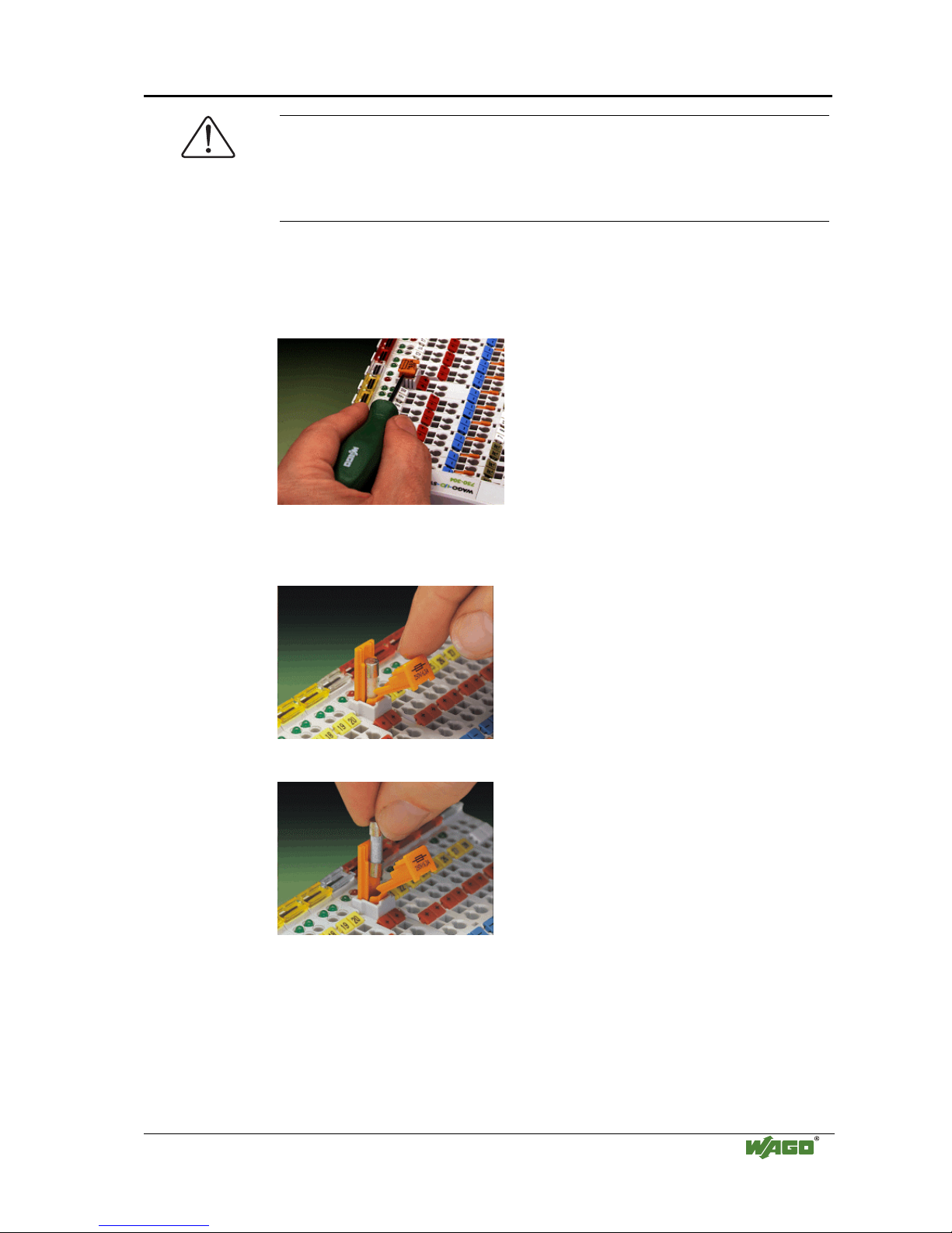
In order to insert or change a fuse, or to switch off the voltage in succeeding
bus modules, the fuse holder may be pulled out. In order to do this, use a
screwdriver for example, to reach into one of the slits (one on both sides) and
pull out the holder.
Fig. 2-15: Removing the fuse carrier
p0xxx05x
Lifting the cover to the side opens the fuse carrier.
Fig. 2-16: Opening the fuse carrier
p0xxx03x
Fig. 2-17: Change fuse
p0xxx04x
After changing the fuse, the fuse carrier is pushed back into its original
position.
Page 30
26 • The WAGO-I/O-SYSTEM 750
Power Supply
WAGO-I/O-SYSTEM 750
ETHERNET TCP/IP
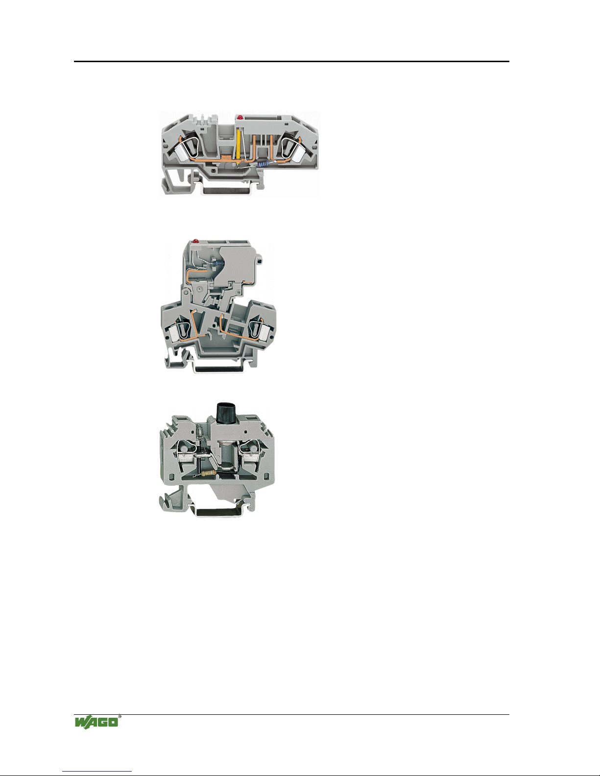
Alternatively, fusing can be done externally. The fuse modules of the WAGO
series 281 and 282 are suitable for this purpose.
Fig. 2-18: Fuse modules for automotive fuses, Series 282
pf66800x
Fig. 2-19: Fuse modules with pivotable fuse carrier, Series 281
pe61100x
Fig. 2-20: Fuse modules, Series 282
pf12400x
Page 31

The WAGO-I/O-SYSTEM 750 • 27
Power Supply
WAGO-I/O-SYSTEM 750
ETHERNET TCP/IP
2.7.4 Supplementary power supply regulations
The WAGO-I/O-SYSTEM 750 can also be used in shipbuilding or offshore
and onshore areas of work (e.g. working platforms, loading plants). This is
demonstrated by complying with the standards of influential classification
companies such as Germanischer Lloyd and Lloyds Register.
Filter modules for 24-volt supply are required for the certified operation of the
system.
Item No. Name Description
750-626 Supply filter Filter module for system supply and field supply (24 V,
0 V), i.e. for field bus coupler / controller and bus power
supply (750-613)
750-624 Supply filter Filter module for the 24 V- field supply
(750-602, 750-601, 750-610)
Therefore, the following power supply concept must be absolutely complied
with.
Fig. 2-21: Power supply concept
g01xx11e
Note
Another potential power terminal 750-601/602/610 must only be used behind
the filter terminal 750-626 if the protective earth conductor is needed on the
lower power contact or if a fuse protection is required.
Page 32

28 • The WAGO-I/O-SYSTEM 750
Power Supply
WAGO-I/O-SYSTEM 750
ETHERNET TCP/IP
2.7.5 Supply example
Note
The system supply and the field supply should be separated in order to ensure
bus operation in the event of a short-circuit on the actuator side.
750-630750-400 750-410 750-401
750-613
750-512 750-512750-616 750-513 750-610 750-552 750-600750-612 750-616
1)
a)
b)
c)
d)
1)
2) 2)
24V
24V
10 A
10 A
L1
L2
L3
N
PE
230V
230V
Main ground bus
Shield (screen) bus
System
Supply
Field
Supply
Field
Supply
1) Separation module
recommended
2) Ring-feeding
recommended
a) Power Supply
on coupler / controller
via external Supply
Module
b) Internal System
Supply Module
c) Supply Module
passive
d)
iagnostics
Supply Module
with fuse carrier/
d
Fig. 2-22: Supply example
g0xxx04e
Page 33

The WAGO-I/O-SYSTEM 750 • 29
Power Supply
WAGO-I/O-SYSTEM 750
ETHERNET TCP/IP
2.7.6 Power Supply Unit
The WAGO-I/O-SYSTEM 750 requires a 24 V direct current system supply
with a maximum deviation of -15% or +20 %.
Recommendation
A stable network supply cannot be taken for granted always and everywhere.
Therefore, regulated power supply units should be used in order to guarantee
the quality of the supply voltage.
A buffer (200 µF per 1 A current load) should be provided for brief voltage
dips. The I/O system buffers for approx 1 ms.
The electrical requirement for the field supply is to be determined individually
for each power supply point. Thereby all loads through the field devices and
bus modules should be considered. The field supply as well influences the bus
modules, as the inputs and outputs of some bus modules require the voltage of
the field supply.
Note
The system supply and the field supply should be isolated from the power
supplies in order to ensure bus operation in the event of short circuits on the
actuator side.
WAGO products
Article No.
Description
787-903 Primary switched - mode, DC 24 V, 5 A
wide input voltage range AC 85-264 V
PFC (Power Factor Correction)
787-904 Primary switched - mode, DC 24 V, 10 A
wide input voltage range AC 85-264 V
PFC (Power Factor Correction)
787-912 Primary switched - mode, DC 24 V, 2 A
wide input voltage range AC 85-264 V
PFC (Power Factor Correction)
288-809
288-810
288-812
288-813
Rail-mounted modules with universal mounting carrier
AC 115 V / DC 24 V; 0,5 A
AC 230 V / DC 24 V; 0,5 A
AC 230 V / DC 24 V; 2 A
AC 115 V / DC 24 V; 2 A
Page 34

30 • The WAGO-I/O-SYSTEM 750
Grounding
WAGO-I/O-SYSTEM 750
ETHERNET TCP/IP
2.8 Grounding
2.8.1 Grounding the DIN Rail
2.8.1.1 Framework Assembly
When setting up the framework, the carrier rail must be screwed together with
the electrically conducting cabinet or housing frame. The framework or the
housing must be grounded. The electronic connection is established via the
screw. Thus, the carrier rail is grounded.
Attention
Care must be taken to ensure the flawless electrical connection between the
carrier rail and the frame or housing in order to guarantee sufficient
grounding.
2.8.1.2 Insulated Assembly
Insulated assembly has been achieved when there is constructively no direct
conduction connection between the cabinet frame or machine parts and the
carrier rail. Here the earth must be set up via an electrical conductor.
The connected grounding conductor should have a cross section of at least
4 mm2.
Recommendation
The optimal insulated setup is a metallic assembly plate with grounding
connection with an electrical conductive link with the carrier rail.
The separate grounding of the carrier rail can be easily set up with the aid of
the WAGO ground wire terminals.
Article No. Description
283-609 Single-conductor ground (earth) terminal block make an automatic
contact to the carrier rail; conductor cross section: 0.2 -16 mm2
Note: Also order the end and intermediate plate (283-320)
Page 35

The WAGO-I/O-SYSTEM 750 • 31
Grounding
WAGO-I/O-SYSTEM 750
ETHERNET TCP/IP
2.8.2 Grounding Function
The grounding function increases the resistance against disturbances from
electro-magnetic interferences. Some components in the I/O system have a
carrier rail contact that dissipates electro-magnetic disturbances to the carrier
rail.
Fig. 2-23: Carrier rail contact
g0xxx10e
Attention
Care must be taken to ensure the direct electrical connection between the
carrier rail contact and the carrier rail.
The carrier rail must be grounded.
For information on carrier rail properties, please see chapter 2.6.3.2.
Page 36

32 • The WAGO-I/O-SYSTEM 750
Grounding
WAGO-I/O-SYSTEM 750
ETHERNET TCP/IP
2.8.3 Grounding Protection
For the field side, the ground wire is connected to the lowest connection
terminals of the power supply module. The ground connection is then
connected to the next module via the Power Jumper Contact (PJC). If the bus
module has the lower power jumper contact, then the ground wire connection
of the field devices can be directly connected to the lower connection
terminals of the bus module.
Attention
Should the ground conductor connection of the power jumper contacts within
the node become disrupted, e.g. due to a 4-channel bus terminal, the ground
connection will need to be re-established.
The ring feeding of the grounding potential will increase the system safety.
When one bus module is removed from the group, the grounding connection
will remain intact.
The ring feeding method has the grounding conductor connected to the
beginning and end of each potential group.
Fig. 2-24: Ring-feeding
g0xxx07e
Attention
The regulations relating to the place of assembly as well as the national
regulations for maintenance and inspection of the grounding protection must
be observed.
Page 37

The WAGO-I/O-SYSTEM 750 • 33
Shielding (Screening)
WAGO-I/O-SYSTEM 750
ETHERNET TCP/IP
2.9 Shielding (Screening)
2.9.1 General
The shielding of the data and signal conductors reduces electromagnetic
interferences thereby increasing the signal quality. Measurement errors, data
transmission errors and even disturbances caused by overvoltage can be
avoided.
Attention
Constant shielding is absolutely required in order to ensure the technical
specifications in terms of the measurement accuracy.
The data and signal conductors should be separated from all high-voltage
cables.
The cable shield should be potential. With this, incoming disturbances can be
easily diverted.
The shielding should be placed over the entrance of the cabinet or housing in
order to already repel disturbances at the entrance.
2.9.2 Bus Conductors
The shielding of the bus conductor is described in the relevant assembly
guideline of the bus system.
2.9.3 Signal Conductors
Bus modules for most analog signals along with many of the interface bus
modules include a connection for the shield.
Note
For better shield performance, the shield should have previously been placed
over a large area. The WAGO shield connection system is suggested for such
an application.
This suggestion is especially applicable when the equipment can have even
current or high impulse formed currents running through it (for example
through atmospheric end loading).
Page 38

34 • The WAGO-I/O-SYSTEM 750
Assembly Guidelines / Standards
WAGO-I/O-SYSTEM 750
ETHERNET TCP/IP
2.9.4 WAGO Shield (Screen) Connecting System
The WAGO Shield Connecting system includes a shield clamping saddle, a
collection of rails and a variety of mounting feet. Together these allow many
dfferent possibilities. See catalog W4 volume 3 chapter 10.
Fig. 2-25: WAGO Shield (Screen) Connecting System
p0xxx08x, p0xxx09x, and p0xxx10x
Fig. 2-26: Application of the WAGO Shield (Screen) Connecting System
p0xxx11x
2.10 Assembly Guidelines / Standards
DIN 60204, Electrical equipping of machines
DIN EN 50178 Equipping of high-voltage systems with electronic
components (replacement for VDE 0160)
EN 60439 Low voltage – switch box combinations
Page 39

Fieldbus Controller • 35
Fieldbus Controller 750-841
WAGO-I/O-SYSTEM 750
ETHERNET TCP/IP
3 Fieldbus Controller
3.1 Fieldbus Controller 750-841
This chapter includes:
3.1.1 Description.........................................................................................36
3.1.2 Compatibility.....................................................................................37
3.1.3 Hardware ...........................................................................................38
3.1.3.1 View..............................................................................................38
3.1.3.2 Device Supply...............................................................................39
3.1.3.3 Fieldbus Connection .....................................................................40
3.1.3.4 Display Elements..........................................................................40
3.1.3.5 Configuration and Programming Interface ...................................41
3.1.3.6 Operating Mode Switch ................................................................42
3.1.3.7 Hardware Address (MAC-ID) ......................................................43
3.1.4 Operating System ..............................................................................44
3.1.4.1 Start-up..........................................................................................44
3.1.4.2 PLC Cycle.....................................................................................44
3.1.5 Process Image....................................................................................46
3.1.5.1 General Structure..........................................................................46
3.1.5.2 Example of a Process Input Image................................................48
3.1.5.3 Example of a Process Output Image.............................................49
3.1.5.4 Fieldbus specific Process Data Architecture for MODBUS/TCP 50
3.1.6 Data Exchange...................................................................................50
3.1.6.1 Memory Areas ..............................................................................67
3.1.6.2 Addressing ....................................................................................69
3.1.6.3 Data Exchange between MODBUS TCP Master and I/O Modules72
3.1.6.4 Data Exchange between Ethernet IP Master and I/O Modules ....74
3.1.6.5 Data Exchange between PLC Functionality (CPU) and I/O
Modules.........................................................................................75
3.1.6.6 Data Exchange between Master and PLC Functionality (CPU)...76
3.1.7 Starting up an ETHERNET TCP/IP fieldbus node ...........................81
3.1.7.1 Variation 1: Start up with the WAGO Ethernet Settings..............81
3.1.7.2 Variation 2:Starting up with the WAGO BootP Server................83
3.1.8 Programming the PFC with WAGO-I/O-PRO CAA.........................90
3.1.8.1 WAGO-I/O-PRO CAA library elements for ETHERNET...........94
3.1.8.2 Some Basic Facts about IEC Tasks ..............................................95
3.1.8.3 IEC 61131-3-Program transfer .....................................................98
3.1.8.4 Information on the web-based management system................... 101
3.1.9 LED Display....................................................................................108
3.1.9.1 Fieldbus status.............................................................................109
3.1.9.2 Node Status – Blink code from the 'I/O' LED ............................110
3.1.9.3 ‘USR‘-LED.................................................................................116
3.1.9.4 Supply voltage status ..................................................................116
3.1.10 Fault behavior..................................................................................117
3.1.10.1 Fieldbus failure ...........................................................................117
3.1.10.2 Internal bus fault.........................................................................117
3.1.11 Technical Data.................................................................................118
Page 40

36 • Fieldbus Controller 750-841
Description
WAGO-I/O-SYSTEM 750
ETHERNET TCP/IP
3.1.1 Description
The WAGO 750-841 Programmable Fieldbus Controller (PFC) combines the
functionality of an ETHERNET fieldbus coupler with the functionality of a
Programmable Logic Controller (PLC). When the PFC is used as a PLC, all
or some of its I/O modules can be control locally with the use of WAGO-I/OPRO CAA. WAGO-I/O-PRO CAA is an IEC 61131-3 programming tool that
is used to program and configure the 750-841 PFC. I/O modules which are
not controlled locally, can be controlled remotely through the 10/100 Mbps
ETHERNET Fieldbus port.
When power is applied to the PFC, it automatically detects all I/O modules
connected to the controller and creates a local process image. This can be a
mixture of analog and digital modules. The process image is subdivided into
an input and an output data area.
The data of the analog modules is mapped first into the process image. The
modules are mapped in the order of their position after the controller. The
digital modules are grouped after the analog modules, in the form of words
(16 bits per word). When the number of digital I/O’s exceeds 16 bits, the
controller automatically starts another word.
The controller has 512 KB of program memory, 128 KB of data memory, and
24 KB of retained memory. The programmer has access to all fieldbus and
I/O data.
To be able to send/receive process data via ETHERNET, the controller
supports a series of network protocols. For the exchange of process data, the
MODBUS TCP (UDP) protocol and the Ethernet/IP protocol are available.
Both communication protocols can be used alternatively or parallel.
The protocol HTTP, BootP, DHCP, DNS, SNTP, FTP, SNMP and SMTP are
provided for the management and diagnosis of the system.
The programmer has the option to use function modules for programming
clients and servers for all transport protocols (TCP, UDP, etc.) via a socketAPI.
Library functions are available to extend the range of programming functions.
The IEC 61131-3 library "SysLibRTC.lib" enables integration of a buffered
real time clock with date (1 second resolution), alarm function, and a timer. In
the event of a power failure, this clock is powered by an auxiliary supply.
The controller is based on a 32-bit CPU and is capable of multitasking (i.e.,
several programs can be run at the same time).
The controller has an internal server for web-based applications. By default,
the controller’s built-in HTML pages contain information on the configuration
and status of the PFC, and can be read using a normal web browser. In
addition, a file system is implemented that allows you to store custom HTML
pages in the controller using FTP download.
Page 41

Fieldbus Controller 750-841 • 37
Compatibility
WAGO-I/O-SYSTEM 750
ETHERNET TCP/IP
3.1.2 Compatibility
WAGO-I/O-PRO 32
759-332
WAGO-I/O-PRO CAA
759-333
Programming
tool:
V2.1 V2.2.6 V2.3.2.5 V2.3.2.7 V2.3.3.4 V2.3.3.6 V2.3.4.3
Controller:
750-841 - -
9 9 9
SW ≥ 06 SW ≥ 09
-
Controller NOT compatible with WAGO-I/O-PRO version
9
Controller compatible with WAGO-I/O-PRO version, independent of the controller hard- or
software
SW ≥ xy
Controller compatible with WAGO-I/O-PRO version if the controller has software xy or higher
Attention
The CoDeSys network variables from WAGO-I/O-PRO V2.3.3.6 and higher
are supported by the controllers 750-841 with the software SW ≥ 06.
The WEB visualisation from WAGO-I/O-PRO V2.3.4.3 and higher are
supported by the controllers 750-841 with the software SW ≥ 09.
Page 42

38 • Fieldbus Controller 750-841
Hardware
WAGO-I/O-SYSTEM 750
ETHERNET TCP/IP
3.1.3 Hardware
3.1.3.1 View
24V 0V
++
_
01
02
7
50-841
LINK
MS
NS
I/O
ETHERNET
C
D
B
A
TxD/RxD
USR
_
0V
fieldbus
connection
RJ 45
configuration and
programming interface
status
voltage supply
-power jumper contacts
-system
data contacts
supply
24V
0V
supply via
power jumper contacts
24V
power jumper contacts
mode switch
flap
open
Fig. 3-1: Fieldbus controller ETHERNET TCP/IP
g084100e
The Fieldbus Controller consists of:
• Device supply with internal system supply module for the system supply as
well as power jumper contacts for the field supply via assembled I/O
modules
• Fieldbus interface with the bus connection
• Display Elements (LED's) for operation status, diagnostics, and
communication status
• Configuration and programming interface port
• Operating mode switch
• Electronics for communication with the I/O modules (internal bus) and the
fieldbus interface
Page 43

Fieldbus Controller 750-841 • 39
Hardware
WAGO-I/O-SYSTEM 750
ETHERNET TCP/IP
3.1.3.2 Device Supply
The PFC is powered via terminal blocks with CAGE CLAMP® connections.
The Device Supply generates the necessary voltages to power the electronics
of the controller and the internal electronics of the connected I/O modules.
1
2
3
4
5
6
7
8
DC
DC
24 V
10 nF
24 V
10 nF
0V
24V/0V
24 V
0V
0V
750-841
FiELDBUS INTERFACE
ELECTRONIC
ELECTRONIC
FiELDBUS
INTERFACE
I/O
MODULES
Fig. 3-2: Device supply
G084101e
The internal electronics of the controller and I/O modules are electrically
isolated from the field-side power connections and field devices by the use of
DC/DC converters and optocouplers
Page 44

40 • Fieldbus Controller 750-841
Hardware
WAGO-I/O-SYSTEM 750
ETHERNET TCP/IP
3.1.3.3 Fieldbus Connection
Connection to the fieldbus is by a RJ45 connector. The RJ45 socket on the
fieldbus controller is wired per the 100BaseTX standard. The specification for
the connecting cable is a twisted pair cable of Category 5. Cables of type SUTP (Screened-Unshielded Twisted Pair) and STP (Shielded Twisted Pair)
with a maximum segment length of 100 meters may be used.
The RJ45 socket is physically lowered for the controller to fit in an 80 mm
high switch box once connected.
The electrical isolation between the fieldbus system and the electronics is
achieved by DC/DC converters and optocouplers in the fieldbus interface.
Contact Signal
1 TD + Transmit +
2 TD - Transmit 3 RD + Receive +
4 free
5 free
6 RD - Receive 7 free
8 free
Fig. 3-3: RJ45-Connector and RJ45 Connector Configuration
3.1.3.4 Display Elements
The operating condition of the controller or the node is displayed with the help
of illuminated indicators in the form of light-emitting diodes (LEDs).
The LED information is routed to the top of the case by light fibres. In some
cases, these are multi-colored (red/green or red/green/orange).
24V 0V
++
01
02
LINK
MS
NS
I/O
ETHERNET
C
D
B
A
TxD/RxD
USR
C
B
A
24V 0V
++
01
02
LINK
MS
NS
I/O
ETHERNET
C
D
B
A
TxD/RxD
USR
C
B
A
C
A
24V 0V
++
01
02
LINK
MS
NS
I/O
ETHERNET
C
D
B
A
TxD/RxD
USR
C
B
A
A
B
C
A
Abb. 3-1: Display Elements 750-841
g084102x
Page 45

Fieldbus Controller 750-841 • 41
Hardware
WAGO-I/O-SYSTEM 750
ETHERNET TCP/IP
LED Color Meaning
LINK green Link to a physical network exists
MS red/green The ‚MS‘-LED indicates the state of the node (Module State)
NS red/green The ‚NS‘-LED indicates the state of the network (Network State)
TxD/RxD green Data exchange taking place
IO red /green
/ orange
The 'I/O'-LED indicates the operation of the node and signals faults
encountered
USR red /green
/ orange
The 'USR' LED can be controlled by a user program in a controller
A green Status of the operating voltage – system
B or C green Status of the operating voltage – power jumper contacts
(LED position is manufacturing dependent)
More Information
The evaluation of the displayed LED signals is described in Chapter 3.1.9
"LED Display".
3.1.3.5 Configuration and Programming Interface
The Configuration and Programming Interface port is located behind a cover
flap. This communications port can be use with WAGO-I/O-CHECK and
WAGO-I/O-PRO CAA, as well as for firmware downloading.
Configuration and
programming interface
Fig. 3-2: Configuration Interface
g01xx07e
A WAGO 750-920 Communication Cable is used to connect the 4 pin male
header and with a PC’s 9-pin RS232 interface.
Page 46

42 • Fieldbus Controller 750-841
Hardware
WAGO-I/O-SYSTEM 750
ETHERNET TCP/IP
3.1.3.6 Operating Mode Switch
The operating mode switch is located behind a cover flap.
Mode switch
UPDATE FIRMWARE
RUN
STOP
RESET
(pushing down)
Fig. 3-4: Operating Mode Switch
g01xx10e
The switch is a push/slide switch with 3 settings and a hold-to-run function.
The slide switch is designed for a maximum number of switching cycles as
defined in EN61131T2.
Operating mode switch Function
From middle to top position Firmware and PFC application are executed (Activate
program processing (RUN)
From top to middle position Firmware is executed, PFC application is stopped (Stop
program processing (STOP)
Lower position, bootstrap Controller starts the operating system loader
Push down
(i.e. with a screwdriver)
Hardware reset
All outputs and flags are reset; variables are set to 0 or to
FALSE or to an initial value.
Retain variables or flags are not changed.
The hardware reset can be performed with STOP as well
as RUN in any position of the operating mode switch!
An operating mode (i.e., RUN/STOP) is internally changed at the end of a
PLC cycle.
Note
The position of the mode switch is not important when starting or stopping
the PFC application from WAGO-I/O-PRO.
Page 47

Fieldbus Controller 750-841 • 43
Hardware
WAGO-I/O-SYSTEM 750
ETHERNET TCP/IP
Attention
If outputs are set when switching from RUN to STOP mode, they remain set!
Switching off the outputs on the software side i.e. by the initiators are
ineffective because the program is no longer processed.
Note
The user has the possibility to define the status of the outputs before a STOP
condition. For this, in the web-based management system a web-page opens
via the PLC link, on that the function can be accordingly specified.
If there is a checkmark in the small box behind "Enabled", all outputs are set
to zero, otherwise the outputs remain to the last current value.
3.1.3.7 Hardware Address (MAC-ID)
Each WAGO ETHERNET TCP/IP fieldbus controller is supplied from the
factory with a unique and internationally unambiguous physical ETHERNET
address, also referred to as MAC-ID (Media Access Control Identity). This is
located on the rear of the controller and on a self-adhesive tear-off label on the
controller’s side. The address has a fixed length of 6 Bytes (48 Bits) and
contains the address type, the manufacturer’s ID, and the serial number.
Page 48

44 • Fieldbus Controller 750-841
Operating System
WAGO-I/O-SYSTEM 750
ETHERNET TCP/IP
3.1.4 Operating System
3.1.4.1 Start-up
The controller starts-up after switching on the supply voltage or after a
hardware reset.
Note
The Operating Mode slide switch must not be in the bottom position during
start-up!
The PLC program in the flash memory is transferred to RAM.
This is followed by the initialization of the system. The controller determines
the I/O modules and the present configuration. The variables are set to 0,
FALSE, or to an initial value given by the PLC program. The flags retain their
status . The "I/O" LED blinks red during this phase.
Following a fault free start-up the controller changes over to "RUN" mode.
The "I/O" LED lights up green.
3.1.4.2 PLC Cycle
The PLC cycle starts following a fault free start-up when the Operating Mode
Switch is in the top position or by a start command from the
WAGO-I/O-PRO CAA. The controller starts a PLC cycle by first reading the
fieldbus data, I/O modules, and time data. Next, the PLC program in RAM is
processed (scanned). After the program is processed, the fieldbus data and I/O
modules are updated with new output data. System functions are then
preformed (i.e., system diagnostics, communications, time calculations, etc).
At this point, if a STOP command is not present, the cycle starts over again
with the reading of the fieldbus data, I/O modules, and time data.
The change of the operating mode (STOP/RUN) is only made at the end of a
PLC cycle.
The cycle time is the time from the start of the PLC program to the next start.
If a sizeable loop is programmed within a PLC program, the PLC cycle time is
extended correspondingly.
The inputs and outputs are not updated during the scanning of the PLC
program. I/O updates only occur at the end of the PLC program scan. For this
reason, it is not possible to wait for a physical I/O change from within a
program loop.
Page 49

Fieldbus Controller 750-841 • 45
Operating System
WAGO-I/O-SYSTEM 750
ETHERNET TCP/IP
Variables are set to 0 or FALSE
or to their initial value,
flags remain in the same status.
Switching on the
supply voltage
Initialization
of the system
Reading inputs, outputs and times
Writing outputs
Fieldbus data,
data of I/O modules
Operating system functions,
updating times
Is a PLC
program in the Flash
memory ?
No
Yes
PLC program transfer
from the flash memory to RAM
Determination of the I/O modules
and the configuration
Test o.k.?
Yes
No
Stop
Test o.k.?
No
Determination of the I/O modules
and the configuration
STOP
Operating mode
Operating mode
STOP
RUN
RUN
Fieldbus data,
data of I/O modules
Yes
Fieldbus start
behaviour as a coupler
operating mode switch
is in the top position or
start command in
WAGO-IO- 32:
or
PRO
Online/Start Online/Stop
operating mode switch
is in the top position or
start command in
WAGO-IO- 32:
or
PRO
Online/Start Online/Stop
“I/O” LED
is blinking
orange
“I/O” LED
is blinking
red
PLC cycle
“I/O” LED
is shining
green
PLC program in the RAM
is processed
Fig. 3-5: Controller Operating System
g012941e
Page 50

46 • Fieldbus Controller 750-841
Process Image
WAGO-I/O-SYSTEM 750
ETHERNET TCP/IP
3.1.5 Process Image
3.1.5.1 General Structure
The powered-up controller recognizes all I/O modules connected in the node
that are waiting to transmit or receive data (data width/bit width > 0). The
maximal length of a node is limited to 64 I/O modules.
Note
Use of the WAGO 750-628 Bus Extension Coupler Module and the 750-627
Extension End Module enables support of up to 250 I/O modules on the
750-841 controller.
Note!
Expansion to 250 I/O modules is enabled in the controllers with
softwareversion ≥ SW 9.
Note
For the number of input and output bits or words of an individual I/O module,
please refer to the corresponding module description later in this chapter.
The controller generates an internal local process image from the data width
and type of I/O modules, as well as the position of the I/O modules in the
node. This image is divided into an input and an output area.
The data of the digital I/O modules are bit-based (i.e., the data exchange is
made by bits). The analog I/O and most specialty modules (e.g., counter
modules, encoder modules, and communication modules) are byte-based, in
which the data exchange is made by bytes.
The process image is divided into an input and an output data area. Each I/O
module is assigned a location in the process image, based on the data
exchange type (i.e., bit-based or byte-based) and their position after the
controller.
All of the byte-based I/O modules are filled in the process image first, then the
bit-based modules. The bits of the digital modules are grouped into a word.
Once the number of digital I/Os exceeds 16 bits, the controller automatically
starts another word.
Note
Changing the physical layout of a node will result in a new structure of the
process image. Also, the addresses of the process data will change. When
adding or removing modules, the process data must be verified.
The process image for physical input and output data is stored in the first 256
words of memory (word 0 to 255). This memory actually consists of a
separate area for the input and output data, but both areas are referenced in a
PLC program with an index of 0 to 255 for word operations.
Page 51

Fieldbus Controller 750-841 • 47
Process Image
WAGO-I/O-SYSTEM 750
ETHERNET TCP/IP
The MODBUS PFC variables are mapped after the process image of the I/O
modules. This memory area contains 256 words (word 256 to 511).
If the quantity of I/O data is greater than 256 words, the additional data is
appended after the MODBUS PFC variables in word 512 to 1275. Like the
first physical I/O process image area, there is a separate memory area for input
and output data, but both are referenced with an index of 512 to 1275 for word
operations.
After the remaining physical I/O data is the Ethernet IP PFC variables. This
memory area is word 1276 to 1531.
For future protocol additions, the area above word 1532 is reserved for
additional PFC variables.
With all WAGO fieldbus controllers, the method used by PLC functions to
access process data is independent of the fieldbus system. This access always
takes place via an application-related IEC 61131-3 program.
In contrast to the above, access from the fieldbus side is fieldbus specific. For
the ETHERNET TCP/IP fieldbus controller, either a MODBUS/TCP master
or an Ethernet/IP master is used. MODBUS/TCP accesses the data via
implemented MODBUS functions. Here decimal and/or hexadecimal
MODBUS addresses are used. With Ethernet/IP, data access occurs with the
use of an object model.
Further information
A detailed description of these fieldbus-specific data access operations is
given in the sections “MODBUS functions” and “Ethernet/IP
(Ethernet/Industrial Protocol)”.
Page 52

48 • Fieldbus Controller 750-841
Process Image
WAGO-I/O-SYSTEM 750
ETHERNET TCP/IP
3.1.5.2 Example of a Process Input Image
The following figure is an example of a process input image. The
configuration includes 16 digital and 8 analog inputs. Therefore, the process
image has a total data length of 9 words (8 words for the analog data and 1
word for the digital inputs).
Bit 1
Bit 4
Word2
Word1
Word2
Word1
Word2
Word1
Word2
Word1
Word2
Word1
Word2
Word1
1
4
1411
4
1
ON
LINK
TxD/RxD
ERROR
Ethernet
750-842
I/O
W
AGO
ßI/O
ßSYSTEM
DI
DI
DI
DI
AI
AI
AI
AI
Word2
Word1
Word2Word2
Word1
Highbyte
Lowbyte
0x0003 %IW3
0x0002 %IW2
0x0001 %IW1
0x0000 %IW0
0x0005 %IW5
0x0004 %IW4
0x0007 %IW7
0x0006 %IW6
0x0008 %IW8
0x0001 %IX8.1
0x0000 %IX8.0
0x0003 %IX8.3
0x0002 %IX8.2
0x0004 %IX8.40x0004 %IX8.4
0x0008 %IX8.8
0x000C %IX8.12
0x0005 %IX8.50x0005 %IX8.5
0x0009 %IX8.9
0x000D %IX8.13
0x0006 %IX8.60x0006 %IX8.6
0x000A %IX8.10
0x000E %IX8.14
0x0007 %IX8.70x0007 %IX8.7
0x000B %IX8.11
0x000F %IX8.15
Process input image
(Word)
addresses
Process input image
(Bit)
Input modules 750- 402 402 472 472 402 476 402 476
DI: Digital Input
AI:Analog Input
addresses
MODBUS PFC
MODBUS PFC
Fig. 3-6: Example of a Process Input Image
G012924e
Page 53

Fieldbus Controller 750-841 • 49
Process Image
WAGO-I/O-SYSTEM 750
ETHERNET TCP/IP
3.1.5.3 Example of a Process Output Image
The following figure is an example of a process output image. The
configuration includes 2 digital and 4 analog outputs. Therefore, the process
image has a total data length of 5 (4 words for the analog data and 1 word for
the digital outputs). When using MODBUS protocol, output data can be read
back with an offset of 200
hex
(0x0200) added to the MODBUS address.
Note
All output data over 256 words can be read back with an offset of 1000
hex
(0x1000) added onto the MODBUS address.
Bit1
Bit2
Word2
Word1
Word2
Word1
Word2
Word1
Word2
Word1
Word2
Word1
Word2
Word1
0x0003 / 0x0203 %QW3
0x0002 / 0x0202 %QW2
0x0001 / 0x0201 %QW1
0x0000 / 0x0200 %QW0
0x0004 / 0x0204 %QW4
0x0203 %QW3
0x0202 %QW2
0x0201 %QW1
0x0200 %QW0
0x0204 %QW4
0x0000 / 0x0200 %QX4.0
0x0001 / 0x0201 %QX4.1
0x0200 %QX4.0
0x0201 %QX4.1
ON
LINK
TxD/RxD
ERROR
Ethernet
750
-842
W
AGO
ßI/O
ßSYSTE M
AO
DO
AO
Highbyte
Lowbyte
Highbyte
Lowbyte
MODBUS addresses
MODBUS addresses
MODBUS addresses
MODBUS addresses
Process output image
(Word)
Process input image
(Word)
Process output image
(Bit)
Process input image
(Bit)
DO: Digital Output
AO: Analog Output
Output modules 750 - 501 550 550
Fig. 3-7: Example of a Process Output Image
G012925e
Page 54

50 • Fieldbus Controller 750-841
Process Image
WAGO-I/O-SYSTEM 750
ETHERNET TCP/IP
3.1.5.4 Fieldbus specific Process Data Architecture for MODBUS/TCP
With some I/O modules, the structure of the process data is fieldbus specific.
In the case of an Ethernet TCP/IP coupler, the process image uses a word
structure (with word alignment). The internal mapping method for data greater
than one byte conforms to the Intel format.
The following section describes the process image for various
WAGO-I/O-SYSTEM 750 I/O modules when using an Ethernet TCP/IP
coupler/controller.
Note
Depending on the specific position of an I/O module in the fieldbus node, the
process data of all previous byte or bit-oriented modules must be taken into
account to determine its location in the process data map.
For the PFC process image of the programmable fieldbus controller is the the
structure of the process data mapping identical.
3.1.5.4.1 Digital Input Modules
Digital input modules supply one bit of data per channel to specify the signal
state for the corresponding channel. These bits are mapped into the Input
Process Image.
When analog input modules are also present in the node, the digital data is
always appended after the analog data in the Input Process Image, grouped
into bytes.
Some digital modules have an additional diagnostic bit per channel in the
Input Process Image. The diagnostic bit is used for detecting faults that occur
(e.g., wire breaks and/or short circuits).
1 Channel Digital Input Module with Diagnostics
750-435
Input Process Image
Bit 7 Bit 6 Bit 5 Bit 4 Bit 3 Bit 2 Bit 1 Bit 0
Diagnostic bit
S 1
Data bit
DI 1
Page 55

Fieldbus Controller 750-841 • 51
Process Image
WAGO-I/O-SYSTEM 750
ETHERNET TCP/IP
2 Channel Digital Input Modules
750-400, -401, -405, -406, -410, -411, -412, -427, -438, (and all variations)
Input Process Image
Bit 7 Bit 6 Bit 5 Bit 4 Bit 3 Bit 2 Bit 1 Bit 0
Data bit
DI 2
Channel
2
Data bit
DI 1
Channel
1
2 Channel Digital Input Modules with Diagnostics
750-419, -421, -424, -425
Input Process Image
Bit 7 Bit 6 Bit 5 Bit 4 Bit 3 Bit 2 Bit 1 Bit 0
Diagnostic
bit S 2
Channel 2
Diagnostic
bit S 1
Channel 1
Data bit
DI 2
Channel
2
Data bit
DI 1
Channel
1
2 Channel Digital Input Module with Diagnostics and Output Process
Data
The 750-418 digital input module supplies a diagnostic and acknowledge bit
for each input channel. If a fault condition occurs, the diagnostic bit is set.
After the fault condition is cleared, an acknowledge bit must be set to reactivate the input. The diagnostic data and input data bit is mapped in the
Input Process Image, while the acknowledge bit is in the Output Process
Image.
Input Process Image
Bit 7 Bit 6 Bit 5 Bit 4 Bit 3 Bit 2 Bit 1 Bit 0
Diagnostic
bit S 2
Channel 2
Diagnostic
bit S 1
Channel 1
Data bit
DI 2
Channel
2
Data bit
DI 1
Channel
1
Output Process Image
Bit 7 Bit 6 Bit 5 Bit 4 Bit 3 Bit 2 Bit 1 Bit 0
Acknowledge
ment bit
Q 2
Channel 2
Acknowledg
ement bit
Q 1
Channel 1
0 0
Page 56

52 • Fieldbus Controller 750-841
Process Image
WAGO-I/O-SYSTEM 750
ETHERNET TCP/IP
4 Channel Digital Input Modules
750-402, -403, -408, -409, -414, -415, -422, -423, -428, -432, -433
Input Process Image
Bit 7 Bit 6 Bit 5 Bit 4 Bit 3 Bit 2 Bit 1 Bit 0
Data bit
DI 4
Channel
4
Data bit
DI 3
Channel
3
Data bit
DI 2
Channel
2
Data bit
DI 1
Channel
1
8 Channel Digital Input Modules
750-430, -431
Input Process Image
Bit 7 Bit 6 Bit 5 Bit 4 Bit 3 Bit 2 Bit 1 Bit 0
Data bit
DI 8
Channel
8
Data bit
DI 7
Channel
7
Data bit
DI 6
Channel
6
Data bit
DI 5
Channel
5
Data bit
DI 4
Channel
4
Data bit
DI 3
Channel
3
Data bit
DI 2
Channel
2
Data bit
DI 1
Channel
1
3.1.5.4.2 Digital Output Modules
Digital output modules use one bit of data per channel to control the output of
the corresponding channel. These bits are mapped into the Output Process
Image.
When analog output modules are also present in the node, the digital image
data is always appended after the analog data in the Output Process Image,
grouped into bytes.
1 Channel Digital Output Module with Input Process Data
750-523
Input Process Image
Bit 7 Bit 6 Bit 5 Bit 4 Bit 3 Bit 2 Bit 1 Bit 0
not
used
Status bit
„Manual
Operation“
Output Process Image
Bit 7 Bit 6 Bit 5 Bit 4 Bit 3 Bit 2 Bit 1 Bit 0
not
used
controls
DO 1
Channel 1
Page 57

Fieldbus Controller 750-841 • 53
Process Image
WAGO-I/O-SYSTEM 750
ETHERNET TCP/IP
2 Channel Digital Output Modules
750-501, -502, -509, -512, -513, -514, -517, -535, (and all variations)
Output Process Image
Bit 7 Bit 6 Bit 5 Bit 4 Bit 3 Bit 2 Bit 1 Bit 0
controls
DO 2
Channel
2
controls
DO 1
Channel
1
2 Channel Digital Input Modules with Diagnostics and Input Process
Data
750-507, -522
The 750-507 and 750-522 digital output modules have a diagnostic bit for
each output channel. When an output fault condition occurs (i.e., overload,
short circuit, or broken wire), a diagnostic bit is set. The diagnostic data is
mapped into the Input Process Image, while the output control bits are in the
Output Process Image.
Input Process Image
Bit 7 Bit 6 Bit 5 Bit 4 Bit 3 Bit 2 Bit 1 Bit 0
Diagnostic
bit S 2
Channel 2
Diagnostic
bit S 1
Channel 1
Output Process Image
Bit 7 Bit 6 Bit 5 Bit 4 Bit 3 Bit 2 Bit 1 Bit 0
controls
DO 2
Channel 2
controls
DO 1
Channel 1
750-506
The 750-506 digital output module has 2-bits of diagnostic information for
each output channel. The 2-bit diagnostic information can then be decoded to
determine the exact fault condition of the module (i.e., overload, a short
circuit, or a broken wire). The 4-bits of diagnostic data are mapped into the
Input Process Image, while the output control bits are in the Output Process
Image.
Input Process Image
Bit 7 Bit 6 Bit 5 Bit 4 Bit 3 Bit 2 Bit 1 Bit 0
Diagnostic
bit S 3
Channel 2
Diagnostic
bit S 2
Channel 2
Diagnostic
bit S 1
Channel 1
Diagnostic
bit S 0
Channel 1
Page 58

54 • Fieldbus Controller 750-841
Process Image
WAGO-I/O-SYSTEM 750
ETHERNET TCP/IP
Output Process Image
Bit 7 Bit 6 Bit 5 Bit 4 Bit 3 Bit 2 Bit 1 Bit 0
not used not used
controls
DO 2
Channel 2
controls
DO 1
Channel 1
4 Channel Digital Output Modules
750-504, -516, -519, -531
Output Process Image
Bit 7 Bit 6 Bit 5 Bit 4 Bit 3 Bit 2 Bit 1 Bit 0
controls
DO 4
Channel
4
controls
DO 3
Channel
3
controls
DO 2
Channel
2
controls
DO 1
Channel
1
4 Channel Digital Output Modules with Diagnostics and Input Process
Data
750-532
The 750-532 digital output modules have a diagnostic bit for each output
channel. When an output fault condition occurs (i.e., overload, short circuit, or
broken wire), a diagnostic bit is set. The diagnostic data is mapped into the
Input Process Image, while the output control bits are in the Output Process
Image.
Input Process Image
Bit 7 Bit 6 Bit 5 Bit 4 Bit 3 Bit 2 Bit 1 Bit 0
Diagnost
ic bit S 3
Channel
4
Diagnost
ic bit S 2
Channel
3
Diagnost
ic bit S 1
Channel
2
Diagnost
ic bit S 0
Channel
1
Diagnostic bit S = '0' no Error
Diagnostic bit S = '1' overload, short circuit, or broken wire
Output Process Image
Bit 7 Bit 6 Bit 5 Bit 4 Bit 3 Bit 2 Bit 1 Bit 0
controls
DO 4
Channel
4
controls
DO 3
Channel
3
controls
DO 2
Channel
2
controls
DO 1
Channel
1
Page 59

Fieldbus Controller 750-841 • 55
Process Image
WAGO-I/O-SYSTEM 750
ETHERNET TCP/IP
8 Channel Digital Output Module
750-530, -536
Output Process Image
Bit 7 Bit 6 Bit 5 Bit 4 Bit 3 Bit 2 Bit 1 Bit 0
controls
DO 8
Channel
8
controls
DO 7
Channel
7
controls
DO 6
Channel
6
controls
DO 5
Channel
5
controls
DO 4
Channel
4
controls
DO 3
Channel
3
controls
DO 2
Channel
2
controls
DO 1
Channel
1
8 Channel Digital Output Modules with Diagnostics and Input Process
Data
750-537
The 750-537 digital output modules have a diagnostic bit for each output
channel. When an output fault condition occurs (i.e., overload, short circuit, or
broken wire), a diagnostic bit is set. The diagnostic data is mapped into the
Input Process Image, while the output control bits are in the Output Process
Image.
Input Process Image
Bit 7 Bit 6 Bit 5 Bit 4 Bit 3 Bit 2 Bit 1 Bit 0
Diagnost
ic bit S 7
Channel
8
Diagnost
ic bit S 6
Channel
7
Diagnost
ic bit S 5
Channel
6
Diagnost
ic bit S 4
Channel
5
Diagnost
ic bit S 3
Channel
4
Diagnost
ic bit S 2
Channel
3
Diagnost
ic bit S 1
Channel
2
Diagnost
ic bit S 0
Channel
1
Diagnostic bit S = '0' no Error
Diagnostic bit S = '1' overload, short circuit, or broken wire
Output Process Image
Bit 7 Bit 6 Bit 5 Bit 4 Bit 3 Bit 2 Bit 1 Bit 0
controls
DO 8
Channel
8
controls
DO 7
Channel
7
controls
DO 6
Channel
6
controls
DO 5
Channel
5
controls
DO 4
Channel
4
controls
DO 3
Channel
3
controls
DO 2
Channel
2
controls
DO 1
Channel
1
3.1.5.4.3 Analog Input Modules
The hardware of an analog input module has 16 bits of measured analog data
per channel and 8 bits of control/status. However, the Ethernet
coupler/controller does not have access to the 8 control/status bits. Therefore,
the Ethernet coupler/controller can only access the 16 bits of analog data per
channel, which are grouped as words and mapped in Intel format in the Input
Process Image.
When digital input modules are also present in the node, the analog input data
is always mapped into the Input Process Image in front of the digital data.
Page 60

56 • Fieldbus Controller 750-841
Process Image
WAGO-I/O-SYSTEM 750
ETHERNET TCP/IP
1 Channel Analog Input Module
750-491, (and all variations)
Input Process Image
Byte Destination
Offset
High Byte Low Byte
Remark
0 D1 D0 Measured Value UD
1 D3 D2 Measured Value U
ref
2 Channel Analog Input Modules
750-452, -454, -456, -461, -462, -465, -466, -467, -469, -472, -474, -475, -476,
-477, -478, -479, -480, -481, -483, -485, -492, (and all variations)
Input Process Image
Byte Destination
Offset
High Byte Low Byte
Remark
0 D1 D0 Measured Value Channel 1
1 D3 D2 Measured Value Channel 2
4 Channel Analog Input Modules
750-453, -455, -457, -459, -460, -468, (and all variations)
Input Process Image
Byte Destination
Offset
High Byte Low Byte
Remark
0 D1 D0 Measured Value Channel 1
1 D3 D2 Measured Value Channel 2
2 D5 D4 Measured Value Channel 3
3 D7 D6 Measured Value Channel 4
3.1.5.4.4 Analog Output Modules
The hardware of an analog output module has 16 bits of measured analog data
per channel and 8 bits of control/status. However, the Ethernet
coupler/controller does not have access to the 8 control/status bits. Therefore,
the Ethernet coupler/controller can only access the 16 bits of analog data per
channel, which are grouped as words and mapped in Intel format in the Output
Process Image.
Page 61

Fieldbus Controller 750-841 • 57
Process Image
WAGO-I/O-SYSTEM 750
ETHERNET TCP/IP
When digital output modules are also present in the node, the analog output
data is always mapped into the Output Process Image in front of the digital
data.
2 Channel Analog Output Modules
750-550, -552, -554, -556, -560, -585, (and all variations)
Output Process Image
Byte Destination
Offset
High Byte Low Byte
Remark
0 D1 D0 Output Value Channel 1
1 D3 D2 Output Value Channel 2
4 Channel Analog Output Modules
750-551, -557, -559
Output Process Image
Byte Destination
Offset
High Byte Low Byte
Remark
0 D1 D0 Output Value Channel 1
1 D3 D2 Output Value Channel 2
2 D5 D4 Output Value Channel 3
3 D7 D6 Output Value Channel 4
3.1.5.4.5 Specialty Modules
WAGO has a host of Specialty I/O modules that perform various functions.
With individual modules beside the data bytes also the control/status byte is
mapped in the process image. The control/status byte is required for the bidirectional data exchange of the module with the higher-ranking control
system. The control byte is transmitted from the control system to the module
and the status byte from the module to the control system.
This allows, for example, setting of a counter with the control byte or
displaying of overshooting or undershooting of the range with the status byte.
Further information
For detailed information about the structure of a particular module’s
control/status byte, please refer to that module’s manual. Manuals for each
module can be found on the Internet under:
http://www.wago.com.
Page 62

58 • Fieldbus Controller 750-841
Process Image
WAGO-I/O-SYSTEM 750
ETHERNET TCP/IP
Counter Modules
750-404, (and all variations except of /000-005)
The above Counter Modules have a total of 5 bytes of user data in both the
Input and Output Process Image (4 bytes of counter data and 1 byte of
control/status). The counter value is supplied as 32 bits. The following tables
illustrate the Input and Output Process Image, which has a total of 3 words
mapped into each image. Word alignment is applied.
Input Process Image
Byte Destination
Offset
High Byte Low Byte
Remark
0 - S Status byte
1 D1 D0
2 D3 D2
Counter Value
Output Process Image
Byte Destination
Offset
High Byte Low Byte
Remark
0 - C Control byte
1 D1 D0
2 D3 D2
Counter Setting Value
750-404/000-005
The above Counter Modules have a total of 5 bytes of user data in both the
Input and Output Process Image (4 bytes of counter data and 1 byte of
control/status). The two counter values are supplied as 16 bits. The following
tables illustrate the Input and Output Process Image, which has a total of 3
words mapped into each image. Word alignment is applied.
Input Process Image
Byte Destination
Offset
High Byte Low Byte
Remark
0 - S Status byte
1 D1 D0 Counter Value of Counter 1
2 D3 D2 Counter Value of Counter 2
Page 63

Fieldbus Controller 750-841 • 59
Process Image
WAGO-I/O-SYSTEM 750
ETHERNET TCP/IP
Output Process Image
Byte Destination
Offset
High Byte Low Byte
Remark
0 - C Control byte
1 D1 D0 Counter Setting Value of Counter 1
2 D3 D2 Counter Setting Value of Counter 2
750-638
The above Counter Modules have a total of 6 bytes of user data in both the
Input and Output Process Image (4 bytes of counter data and 2 bytes of
control/status). The two counter values are supplied as 16 bits. The following
tables illustrate the Input and Output Process Image, which has a total of 4
words mapped into each image. Word alignment is applied.
Input Process Image
Byte Destination
Offset
High Byte Low Byte
Remark
0 - S0 Status byte of Counter 1
1 D1 D0 Counter Value of Counter 1
2 - S1 Status byte of Counter 2
3 D3 D2 Counter Value of Counter 2
Output Process Image
Byte Destination
Offset
High Byte Low Byte
Remark
0 - C0 Control byte of Counter 1
1 D1 D0 Counter Setting Value of Counter 1
2 - C1 Control byte of Counter 2
3 D3 D2 Counter Setting Value of Counter 2
Pulse Width Modules
750-511, (and all variations)
The above Pulse Width modules have a total of 6 bytes of user data in both the
Input and Output Process Image (4 bytes of channel data and 2 bytes of
control/status). The two channel values are supplied as 16 bits. Each channel
has its own control/status byte. The following table illustrates the Input and
Output Process Image, which has a total of 4 words mapped into each image.
Word alignment is applied.
Page 64

60 • Fieldbus Controller 750-841
Process Image
WAGO-I/O-SYSTEM 750
ETHERNET TCP/IP
Input and Output Process Image
Byte Destination
Offset
High Byte Low Byte
Remark
0 - C0/S0 Control/Status byte of Channel 1
1 D1 D0 Data Value of Channel 1
2 - C1/S1 Control/Status byte of Channel 2
3 D3 D2 Data Value of Channel 2
Serial Interface Modules with alternative Data Format
750-650, (and the variations /000-002, -004, -006, -009, -010, -011, -012,
-013)
750-651, (and the variations /000-002, -003)
750-653, (and the variations /000-002, -007)
Note:
With the freely parametrizable variations /003 000 of the serial interface
modules, the desired operation mode can be set. Dependent on it, the
process image of these modules is then the same, as from the appropriate
variation.
The above Serial Interface Modules with alternative data format have a total
of 4 bytes of user data in both the Input and Output Process Image (3 bytes of
serial data and 1 byte of control/status). The following table illustrates the
Input and Output Process Image, which have a total of 2 words mapped into
each image. Word alignment is applied.
Input and Output Process Image
Byte Destination
Offset
High Byte Low Byte
Remark
0 D0 C/S Data byte Control/Status byte
1 D2 D1 Data bytes
Serial Interface Modules with Standard Data Format
750-650/000-001, -014, -015, -016
750-651/000-001
750-653/000-001, -006
The above Serial Interface Modules with Standard Data Format have a total of
6 bytes of user data in both the Input and Output Process Image (5 bytes of
serial data and 1 byte of control/status). The following table illustrates the
Input and Output Process Image, which have a total of 3 words mapped into
each image. Word alignment is applied.
Page 65

Fieldbus Controller 750-841 • 61
Process Image
WAGO-I/O-SYSTEM 750
ETHERNET TCP/IP
Input and Output Process Image
Byte Destination
Offset
High Byte Low Byte
Remark
0 D0 C/S Data byte Control/Status byte
1 D2 D1
2 D4 D3
Data bytes
Data Exchange Module
750-654, (and the variation /000-001)
The Data Exchange modules have a total of 4 bytes of user data in both the
Input and Output Process Image. The following tables illustrate the Input and
Output Process Image, which has a total of 2 words mapped into each image.
Word alignment is applied.
Input and Output Process Image
Byte Destination
Offset
High Byte Low Byte
Remark
0 D1 D0
1 D3 D2
Data bytes
SSI Transmitter Interface Modules
750-630, (and all variations)
The above SSI Transmitter Interface modules have a total of 4 bytes of user
data in the Input Process Image, which has 2 words mapped into the image.
Word alignment is applied.
Input Process Image
Byte Destination
Offset
High Byte Low Byte
Remark
0 D1 D0
1 D3 D2
Data bytes
Page 66

62 • Fieldbus Controller 750-841
Process Image
WAGO-I/O-SYSTEM 750
ETHERNET TCP/IP
Incremental Encoder Interface Modules
750-631
The above Incremental Encoder Interface modules have 5 bytes of input data
and 3 bytes of output data. The following tables illustrate the Input and Output
Process Image, which have 4 words into each image. Word alignment is
applied.
Input Process Image
Byte Destination
Offset
High Byte Low Byte
Remark
0 - S not used Status byte
1 D1 D0 Counter word
2 - - not used
3 D4 D3 Latch word
Output Process Image
Byte Destination
Offset
High Byte Low Byte
Remark
0 - C not used Control byte
1 D1 D0 Counter Setting word
2 - - not used
3 - - not used
750-634
The above Incremental Encoder Interface module has 5 bytes of input data (6
bytes in cycle duration measurement mode) and 3 bytes of output data. The
following tables illustrate the Input and Output Process Image, which has 4
words mapped into each image. Word alignment is applied.
Input Process Image
Byte Destination
Offset
High Byte Low Byte
Remark
0 - S not used Status byte
1 D1 D0 Counter word
2 - (D2)*) not used (Periodic time)
3 D4 D3 Latch word
*) If cycle duration measurement mode is enabled in the control byte, the cycle
duration is given as a 24-bit value that is stored in D2 together with D3/D4.
Page 67

Fieldbus Controller 750-841 • 63
Process Image
WAGO-I/O-SYSTEM 750
ETHERNET TCP/IP
Output Process Image
Byte Destination
Offset
High Byte Low Byte
Remark
0 - C not used Control byte
1 D1 D0 Counter Setting word
2 - 3 - -
not used
750-637
The above Incremental Encoder Interface Module has a total of 6 bytes of user
data in both the Input and Output Process Image (4 bytes of encoder data and
2 bytes of control/status). The following table illustrates the Input and Output
Process Image, which have 4 words mapped into each image. Word alignment
is applied.
Input and Output Process Image
Byte Destination
Offset
High Byte Low Byte
Remark
0 - C0/S0 Control/Status byte of Channel 1
1 D1 D0 Data Value of Channel 1
2 - C1/S1 Control/Status byte of Channel 2
3 D3 D2 Data Value of Channel 2
750-635
The above Digital Pulse Interface module has a total of 4 bytes of user data in
both the Input and Output Process Image (3 bytes of module data and 1 byte of
control/status). The following table illustrates the Input and Output Process
Image, which have 2 words mapped into each image. Word alignment is
applied.
Input and Output Process Image
Byte Destination
Offset
High Byte Low Byte
Remark
0 D0 C0/S0 Data byte Control/Status byte
1 D2 D1 Data bytes
DALI/DSI Master Module
750-641
The DALI/DSI Master module has a total of 6 bytes of user data in both the
Input and Output Process Image (5 bytes of module data and 1 byte of
control/status). The following tables illustrate the Input and Output Process
Image, which have 3 words mapped into each image. Word alignment is
applied.
Page 68

64 • Fieldbus Controller 750-841
Process Image
WAGO-I/O-SYSTEM 750
ETHERNET TCP/IP
Input Process Image
Byte Destination
Offset
High Byte Low Byte
Remark
0 D0 S DALI Response Status byte
1 D2 D1 Message 3 DALI Address
3 D4 D3 Message 1 Message 2
Output Process Image
Byte Destination
Offset
High Byte Low Byte
Remark
0 D0 C
DALI command,
DSI dimming value
Control byte
1 D2 D1 Parameter 2 DALI Address
3 D4 D3 Command-
Extension
Parameter 1
EnOcean Radio Receiver
750-642
The EnOcean radio receiver has a total of 4 bytes of user data in both the Input
and Output Process Image (3 bytes of module data and 1 byte of
control/status). The following tables illustrate the Input and Output Process
Image, which have 2 words mapped into each image. Word alignment is
applied.
Input Process Image
Byte Destination
Offset
High Byte Low Byte
Remark
0 D0 S Data byte Status byte
1 D2 D1 Data bytes
Output Process Image
Byte Destination
Offset
High Byte Low Byte
Remark
0 - C not used Control byte
1 - - not used
MP Bus Master Module
750-643
The MP Bus Master Module has a total of 8 bytes of user data in both the
Input and Output Process Image (6 bytes of module data and 2 bytes of
control/status). The following table illustrates the Input and Output Process
Image, which have 4 words mapped into each image. Word alignment is
applied.
Page 69

Fieldbus Controller 750-841 • 65
Process Image
WAGO-I/O-SYSTEM 750
ETHERNET TCP/IP
Input and Output Process Image
Byte Destination
Offset
High Byte Low Byte
Remark
0 C1/S1 C0/S0
extended
Control/Status byte
Control/Status byte
1 D1 D0
2 D3 D2
3 D5 D4
Data bytes
AS-interface Master Module
750-655
The length of the process image of the AS-interface master module can be set
to fixed sizes of 12, 20, 24, 32, 40 or 48 bytes.
It consists of a control or status byte, a mailbox with a size of 0, 6, 10, 12 or
18 bytes and the AS-interface process data, which can range from 0 to 32
bytes.
The AS-interface master module has a total of 6 to maximally 24 words data
in both the Input and Output Process Image. Word alignment is applied.
The first Input and output word, which is assigned to an AS-interface master
module, contains the status / control byte and one empty byte.
Subsequently the mailbox data are mapped, when the mailbox is permanently
superimposed (Mode 1).
In the operating mode with suppressable mailbox (Mode 2), the mailbox and
the cyclical process data are mapped next.
The following words contain the remaining process data.
Input and Output Process Image
Byte Destination
Offset
High Byte Low Byte
Remark
0 - C0/S0 not used Control/Status byte
1 D1 D0
2 D3 D2
3 D5 D4
... ... ...
max. 23 D45 D44
Mailbox (0, 3, 5, 6 or 9 words) /
Process data (0-16 words)
3.1.5.4.6 System Modules
System Modules with Diagnostics
750-610, -611
The 750-610 and 750-611 Supply Modules provide 2 bits of diagnostics in the
Input Process Image for monitoring of the internal power supply.
Input Process Image
Bit 7 Bit 6 Bit 5 Bit 4 Bit 3 Bit 2 Bit 1 Bit 0
Diagnostic bit S 2
Fuse
Diagnostic bit S 1
Voltage
Page 70

66 • Fieldbus Controller 750-841
Data Exchange
WAGO-I/O-SYSTEM 750
ETHERNET TCP/IP
3.1.6 Data Exchange
The ETHERNET TCP/IP fieldbus controller can be configured for either
MODBUS/TCP or the Ethernet IP protocol.
MODBUS/TCP works according to the master/ model. The master (e.g., a PC
or a PLC) will query a slave device and the slave will return a response to the
master depending on the kind of query. Queries are addressed to a specific
node through the use of the IP address.
Typically, the ETHERNET TCP/IP controller of the WAGO-I/O-SYSTEM is
a slave device. But, with the use of the WAGO-I/O-PRO CAA programming
tool, the PFC can additionally perform master functions.
A controller is able to produce a defined number of simultaneous socket
connections to other network subscribers:
•
3 connections for HTTP (read HTML pages from the controller),
•
15 connections via MODBUS/TCP (read or write input and output data
from the controller),
•
128 Ethernet IP connections,
•
5 connections via the PFC (available for IEC 61131-3 application
programs)
•
2 connections for WAGO-I/O-PRO CAA (these connections are reserved
for debugging the application program via ETHERNET.
For debugging, WAGO-I/O-PRO CAA requires 2 connections at the same
time. However, only one programming tool can have access to the
controller.
•
10 connections for FTP
•
2 connections for SNMP
The maximum number of simultaneous connections may not be exceeded. If
you wish to establish further connections, terminate an existing connection
first.
For data exchange, the ETHERNET TCP/IP fieldbus controller uses three main
interfaces:
•
interface to the fieldbus (master),
•
the PLC functionality of the PFCs (CPU) and
•
the interface to the I/O Modules.
Data exchange takes place between the fieldbus master and the I/O modules,
between the PLC functionality of the controller and the I/O modules as well as
between the fieldbus master and the PLC functionality of the controller.
Currently, the 750-841 supports MODBUS/TCP and ETHERNET IP based
master devices. When the controller performs PLC functions, and controls
various I/O modules, this is done with the use of an IEC 61131-3 application
program, whereby the data addressing is different than the fieldbus addressing.
Page 71

Fieldbus Controller 750-841 • 67
Data Exchange
WAGO-I/O-SYSTEM 750
ETHERNET TCP/IP
3.1.6.1 Memory Areas
12
2
4
4
CPU
I
O
11
1
3
1
Programmable Fieldbus Controller
memory area
for input data
input
modules
IEC 61131program
memory area
for output data
fieldbus
master
I/O modules
word 1276
word 1531
word 0
word 255
word 256
MODBUS
PFC-OUTvariables
word 511
word 1276
Ethernet IP
PFC-OUTvariables
word 1531
word 1275
word 512
word 0
word 255
word 256
MODBUS
PFC-INvariables
word 511
word 512
word 1275
Ethernet IP
PFC-INvariables
input
modules
output
modules
output
modules
Fig. 3-8: Memory Areas and Data Exchange for a Fieldbus Controller
g015038e
The PFC‘s process image contains the physical data of the I/O modules in
memory words 0 to 255 and 512 to 1275.
(1) Reading data of the input modules is possible from both the controller’s
CPU and from the fieldbus master (See Figure 3-8).
(2) In the same manner, writing data to output modules is possible from both
the controller’s CPU and from the fieldbus master.
The controller’s process image also contains variables called “PFC Variables”.
These variables are allocated based on the fieldbus protocols. The MODBUS
TCP PFC variables are stored in memory from word 256 to 511. Ethernet IP
PFC variables are stored in memory from word 1276 to 1531. The memory
area above word 1531 is reserved for future protocols.
(3) The PFC input variables are written into the input memory space from the
fieldbus master and can be read by the controller’s CPU for further
processing.
(4) The variables processed by the controller’s CPU , via an IEC 61131-3
application program, can be written to the PFC Variables and then read by
the fieldbus master.
Page 72

68 • Fieldbus Controller 750-841
Data Exchange
WAGO-I/O-SYSTEM 750
ETHERNET TCP/IP
In addition, with the MODBUS TCP/IP protocol, all output data has a
mirrored image in memory with the address offset 0x0200 or 0x1000. This
permits reading back output values after they are written by adding 0x0200 or
0x1000 to the MODBUS address.
In addition, the controller offers other memory spaces which partly cannot be
accessed from the fieldbus master:
RAM
Memory
256 kByte
The RAM memory is used to create variables not required for
communication with the interfaces but for internal processing,
such as for instance computation of results.
CodeMemory
512 kByte
The IEC 61131-3 program is filed in the code memory. The code
memory is a flash ROM. Once the supply voltage is applied, the
program is transmitted from the flash to the RAM memory.
After a successful start-up, the PFC cycle starts when the
operating mode switch is turned to its upper position or by a
start command from WAGO-I/O-PRO CAA.
NOVRAM
Remanent
Memory
24 kByte
(Retain)
The remanent memory is non volatile memory, i.e. all values are
retained following a voltage failure. The memory management is
automatic. This 24 kByte sized memory area (word 0 ... 12288)
devides on into a 8 kByte sized addressable range for the flags
(%MW0... %MW4095) and a 16 kByte sized Retain range for
variables without memory space addressing or variables which
are explicitly defined with "var retain".
Note
The allocation of the NORAM is if necessary changeable in the
programming software WAGO-I/O-PRO CAA/
register: "Ressourcen"/dialog: "Target Settings" (see picture).
The start address for the flag range is thereby firmly addressed
with 16#30000000. The range sizes and the start address of the
Retain memory are variable. To exclude a data overlap of the
ranges, it is however recommended, to maintain the default
settings. Thereby the size of the flag range is given with
16#2000 and subsequently to it the Retain memory has the start
address 16#30002000 and the size of 16#4000.
Page 73

Fieldbus Controller 750-841 • 69
Data Exchange
WAGO-I/O-SYSTEM 750
ETHERNET TCP/IP
3.1.6.2 Addressing
3.1.6.2.1 Addressing the I/O Modules
The arrangement of the I/O modules in a node is flexible and up to the user.
Although, the user must verify that the power jumper contacts from one I/O
module to the next are compatible and at the same voltage level.
When the controller addresses I/O modules, data of complex modules (modules
occupying 1 or more bytes) are mapped first. They are mapped in the order of
their physical position after the controller. As such, they occupy the addresses
beginning with word 0. Following this, the digital modules are grouped in the
form of words (16 bits per word). They are also arranged by their physical
order. When the number of digital I/O’s exceeds 8 bits, the controller
automatically starts another byte.
Note
For detailed information on the number of input and output bits/bytes of a
specific module, please refer to the modules manual.
Note
Changing the physical layout of a node will result in a new structure of the
process image. Also, the addresses of the process data will change. When
adding or removing modules, the process data must be verified.
Data width ≥ 1 Word / channel Data width = 1 Bit / channel
Analog input modules Digital input modules
Analog output modules Digital output modules
Input modules for thermal elements Digital output modules with diagnosis (2 Bit / channel)
Input modules for resistance sensors Power supply modules with fuse holder / diagnosis
Pulse width output modules Solid State power relay
Interface module Relay output modules
Up/down counter
I/O modules for angle and path measurement
Table 3.1: I/O Module Data Width
3.1.6.2.2 Address Range
Partition of Address ranges for the word-wise addressing acc. to IEC 61131-3 :
Word Data
0-255 physical I/O modules
256-511 MODBUS/TCP PFC variables
512-1275 remaining physical I/O modules
1276-1531 Ethernet/IP PFC variables
1532-..... reserved for PFC variables of future protocols
Page 74

70 • Fieldbus Controller 750-841
Data Exchange
WAGO-I/O-SYSTEM 750
ETHERNET TCP/IP
Word 0-255: First address range I/O module data:
Data Address
Bit
0.0 ...
0.7
0.8...
0.15
1.0 ...
1.7
1.8...
1.15
..... 254.0 ...
254.7
254.8...
254.15
255.0 ...
255.7
255.8...
255.15
Byte
0 1 2 3 ..... 508 509 510 511
Word
0 1 ..... 254 255
DWord
0 ..... 127
Table. 32: First Address Range for the I/O Module Data
Word 256-511: Address range for MODBUS/TCP fieldbus data:
Data Address
Bit
256.0
...
256.7
256.8
...
256.15
257.0
...
257.7
257.8
...
257.15
..... 510.0
...
510.7
510.8
...
510.15
511.0
...
511.7
511.8
...
511.15
Byte
512 513 514 515 ..... 1020 1021 1022 1023
Word
256 257 ..... 510 511
DWord
128 ..... 255
Table 3.3: Address Range for the MODBUS/TCP Fieldbus Data
Word 512-1275: Second address range I/O module data:
Data Address
Bit
512.0.
512.7
512.8...
512.15
513.0 ..
513.7
513.8...
513.15
..... 1274.0..
1274.7
1274.8..
1274.15
1275.0 ...
1275.7
1275.8...
1275.15
Byte
1024 1025 1026 1027 ..... 2548 2549 2550 2551
Word
512 513 ..... 1274 1275
DWord
256 ..... 637
Table 3.4: Second Address Range for the I/O Module Data
Word 1276-1531: Address range for Ethernet/IP fieldbus data:
Data Address
Bit
1276.0
...
1276.7
1276.8
...
1276.15
1277.0
...
1277.7
1277.8
...
1277.15
...
1530.0
...
1530.7
1530.8
...
1530.15
1531.0
...
1531.7
1531.8
...
1531.15
Byte
2552 2553 2554 2555
...
3060 3061 3062 3063
Word
1276 1277
...
1530 1531
DWord
638
...
765
Table 3.5: Address Range for the Ethernet IP Fieldbus Data
Address range for flags (Retain Variables):
Data Address
Bit
0.0 ...
0.7
0.8...
0.15
1.0...
1.7
1.8...
1.15
..... 12287.0..
12287.7
12287.8..
12287.15
12288.0 ...
12288.7
12288.8...
12288.15
Byte
0 1 2 3 ..... 24572 24573 24574 24575
Word
0 1 ..... 12287 12288
DWord
0 ..... 6144
Table 3.6: Address Range for Flags (Retain Variables)
Page 75

Fieldbus Controller 750-841 • 71
Data Exchange
WAGO-I/O-SYSTEM 750
ETHERNET TCP/IP
Overview of the IEC 61131-3 address ranges:
Address range MODBUS
Access
SPS
Access
Description
phys. Inputs read read Physical Inputs (%IW0 ... %IW255 and
%IW512 ... %IW1275)
phys. Outputs read/write read/write Physical Outputs (%QW0 ... %QW255 and
%QW512 ... %QW1275)
MODBUS/TCP
PFC IN variables
read/write read Volatile SPS Input variables (%IW256 ... %IW511)
MODBUS/TCP
PFC OUT variables
read read/write Volatile SPS Output variables (%QW256 ... %QW511)
Ethernet/IP
PFC IN variables
- read Volatile SPS Input variables (%IW1276 ... %IW1531)
Ethernet/IP
PFC OUT variables
- read/write Volatile SPS Output variables (%QW1276 ... %QW1531)
Configuration register read/write --- see Chapter „Ethernet“
Firmware register read --- see Chapter „Ethernet“
Flags/RETAIN
variables
read/write read/write Remanent memory (%MW0 ... %MW12288)
Table 3.7: Overview IEC 61131-3 Address ranges
3.1.6.2.3 Absolute Addresses
Accessing individual memory cells (absolute addresses) in accordance with
IEC 61131-3 is made using special character defined in the table below:
Position Character Designation Comments
1 % Starts absolute address
2 I Input
Q Output
M Flag
3 X* Single bit Data width
B Byte (8 Bits)
W Word (16 Bits)
D Double word (32 Bits)
4 Address
e. g. word wise: %QW27 (28. Word), bit wise: %IX1.9 (10. Bit in Word 2)
* The character ‘X’ for bits can be deleted
Table 3.8: Absolute Addresses
Note
Enter the absolute address character strings without blanks (white spaces)!
Page 76

72 • Fieldbus Controller 750-841
Data Exchange
WAGO-I/O-SYSTEM 750
ETHERNET TCP/IP
Addressing Example:
Address calculation (depending upon the word address):
Bit address: word address .0 to .15
Byte address: 1. Byte: 2 x word address
2. Byte: 2 x word address + 1
Dword address:
word address (even numbers) / 2
or word address (uneven numbers) / 2, rounded off
3.1.6.3 Data Exchange between MODBUS TCP Master and I/O Modules
The data exchange between the MODBUS TCP master and the I/O modules is
made via the Ethernet Fieldbus port using MODBUS TCP read and write
commands.
The controller handles four different types of process data with MODBUS
TCP:
•
Input words
•
Output words
•
Input bits
•
Output bits
The relationship between bits and words are defined in the table below:
Digital inputs/outputs
16. 15. 14. 13. 12. 11. 10. 9. 8. 7. 6. 5. 4. 3. 2. 1.
Prozess data word
Bit
15
Bit
14
Bit
13
Bit
12
Bit
11
Bit
10
Bit9 Bit8 Bit7 Bit6 Bit 5 Bit 4 Bit 3 Bit 2 Bit1 Bit
0
High-Byte Low-Byte
Byte
D1 D0
Table 3.9: Allocation of Digital Inputs/Outputs to Process Data Word in Intel Format
Page 77

Fieldbus Controller 750-841 • 73
Data Exchange
WAGO-I/O-SYSTEM 750
ETHERNET TCP/IP
Adding an offset of 0x0200 to the MODBUS output address lets you read
back output data.
Note
For MODBUS mapping, all output data over 256 words resides in the
memory area 0x6000 to 0x62FC, and can be read back with an offset of
1000
hex
(0x1000) added onto the MODBUS address.
0x0000
0x00FF
0x0000
(0x0200)
00x0FF
(0x02FF)
0x6000
0x62FC
0x6000
(0x7000)
0x62FC
(0x72FC)
PII = Process Input
Image
PIO = Process Output
Image
MODBUS master
PII
PIO
I/O modules
Inputs
Outputs
Programmable Fieldbus Controller
Fig. 3-9: Data exchange between MODBUS master and I/O modules
g015045e
The MODBUS register assignments allow for a Fieldbus Master to read and
write data from the controller. The register mapping for IEC 61131.1 varies
from the MODBUS assignments. Please refer to section 3.1.5.6.2 for a
comparison of MODBUS TCP and IEC 61131.1 address mapping.
Page 78

74 • Fieldbus Controller 750-841
Data Exchange
WAGO-I/O-SYSTEM 750
ETHERNET TCP/IP
3.1.6.4 Data Exchange between Ethernet IP Master and I/O Modules
Data exchange between the Ethernet IP master and the I/O modules is object
oriented. Each node in the network is represented as a collection of objects.
The “assembly” object defines the structure of objects for data transfer. With
the assembly object, data (e.g. I/O data) can be grouped into blocks (mapped)
and sent via a single communication link. As a result of this mapping
technique, fewer access operations to the network are required.
Input and output assemblies have different functions.
An input assembly reads data from the application over the network or
produces data on the network.
Where as, an output assembly writes data to the application or consumes data
from the network.
Various assembly instances are permanently pre-programmed in the fieldbus
controller (static assembly).
After switching on the power supply, the assembly object maps data from the
process image. As soon as a connection is established, the master can address
the data with "class", "instance" and "attribute" and access or read and/or write
the data via I/O links.
The mapping of the data depends on the chosen assembly instance of the static
assembly.
Further information
The assembly instances for the static assembly are described in the section
7.3.2.6 "Assembly (04 hex)".
Page 79

Fieldbus Controller 750-841 • 75
Data Exchange
WAGO-I/O-SYSTEM 750
ETHERNET TCP/IP
3.1.6.5 Data Exchange between PLC Functionality (CPU) and I/O Modules
Through absolute addresses, the PLC functionality of the controller can
directly address the I/O module data.
The PFC addresses the input data with absolute addresses. The data can then
be processed, internally in the controller, through the IEC 61131-3 program,
whereby the flags are filed in a permanent memory area. Following this, the
linking results can be directly written in the output data via absolute
addressing.
%IW0 %QW0
%QW255%IW255
%IW512
%IW1275
%QW512
%QW1275
PII = Process Input
Image
PIO = Process Output
Image
Inputs
Outputs
I/O modules
750-4xx....6xx
PII
PIO
PLC functionality (CPU)
Inputs
Outputs
Programmable Fieldbus Controller
Fig. 3-10: Data exchange between PLC functionality (CPU) and I/O modules
15043e
Page 80

76 • Fieldbus Controller 750-841
Data Exchange
WAGO-I/O-SYSTEM 750
ETHERNET TCP/IP
3.1.6.6 Data Exchange between Master and PLC Functionality (CPU)
The fieldbus master and the PLC functionality of the controller regard the data
in a different manner.
Variable data created by the fieldbus master reaches the PFC as input
variables. Data created in the PFC is sent to the fieldbus master through
output variables.
In the PFC, the controller can access the MODBUS TCP PFC variable data
from word address 256 to 511 (double word address 128-255, byte address
512-1023) and the Ethernet IP PFC variable data from word address 1276 to
1531 (double word address 638-765, byte address 2552-3063).
3.1.6.6.1 Example MODBUS TCP Master and PLC functionality (CPU)
Data Access by the MODBUS TCP Master
With MODBUS TCP, the fieldbus master can access controller data as words
or bits.
When accessing the first 256 words of memory from the Fieldbus port
(physical I/O modules), the I/O modules start with the address 0 for both bit
and word access.
When accessing data from the starting memory address of 256, the bit and
word addresses follow the sequence below:
4096 for bit 0 in word 256
4097 for bit 1 in word 256
...
8191 for bit 15 in word 511.
The bit number can be calculated from the following formula:
BitNo = (Word * 16) + Bitno_in_Word
Data Access by the PLC Functionality
When accessing the same data from both a PLC and Fieldbus master, the
following memory address conventions should be understood:
A 16 bit IEC 61131-3 variable uses the same addressing as the MODBUS
word format.
An IEC 61131-3 boolean variable (1 bit) uses a “WORD.BIT” notation for
addressing, which is different from MODBUS’s bit notation.
The “WORD.BIT” notation is composed of the boolean’s word address and
bit number in the word, separated by a dot. The Word and Bit values are zero
based (e.g., %IX0.0 is the first possible digital input).
Page 81

Fieldbus Controller 750-841 • 77
Data Exchange
WAGO-I/O-SYSTEM 750
ETHERNET TCP/IP
Example:
MODBUS bit number 19 => bit addressing in PLC <Wordno>.<Bitno> = 1.2
The PLC functionality of the PFC can also access the data as Bytes and
Double- Words.
The byte addresses are computed according to the following formula:
High-Byte Address = Word address*2
Low-Byte Address = (Word address*2) + 1
The double word address is computed according to the following formula:
Double word address = High word address/2 (rounded off)
or = Low word address/2
Page 82

78 • Fieldbus Controller 750-841
Data Exchange
WAGO-I/O-SYSTEM 750
ETHERNET TCP/IP
3.1.6.6.2 Comparison of MODBUS TCP Addresses and IEC 61131-3 Addresses
3.1.6.6.2.1 Word Access
MODBUS Addresses Method
decimal hexadecimal
IEC1131 Addresses Description
0...
255
0x0000 –
0x00FF
%IW0...
%IW255
phys. Inputs (1)
256...
511
0x0100 –
0x01FF
%QW256...
%QW511
PFC OUT variables
512 ...
767
0x0200 –
0x02FF
%QW0...
%QW255
phys. Outputs (1)
768 ...
1023
0x0300 –
0x03FF
%IW256...
%IW511
PFC IN variables
illegal Address 0x0400 –
0x0FFF
not supported
4096...
8191
0x1000 –
0x1FFF
not supported Configuration register
8192 ...
12287
0x2000 -
0x2FFF
not supported Firmware register
12288...
13385
0x3000 -
0x3FFF
%MW0...
%MW4095
Flags range (default:
8kByte, size changeable)
24576 ...
25340
0x6000-
0x62FC
%IW512...
%IW1275
phys. Inputs (2)
FC3
- Read Multiple Register
FC4
– Read Holding Register
28672 ...
29436
0x7000-
0x72FC
%QW512...
%QW1275
phys. Outputs (2)
0...
255
0x0000 –
0x00FF
%QW0...
%QW255
phys. Outputs (1)
256...
511
0x0100 –
0x01FF
%IW256...
%IW511
PFC IN variables
512...
767
0x0200 –
0x02FF
%QW0...
%QW255
phys. Outputs (1)
768 ...
1023
0x0300 –
0x03FF
%IW256...
%IW511
PFC IN variables
illegal Address 0x0400 –
0x0FFF
not supported
4096...
8191
0x1000 –
0x1FFF
not supported Configuration register
illegal Address 0x2000 -
0x2FFF
not supported Firmware register
12288...
13385
0x3000 -
0x3FFF
%MW0...
%MW4095
Flags range (default:
8kByte, size changeable)
24576 ...
25340
0x6000-
0x62FC
%QW512...
%QW1275
phys. Outputs (2)
FC16
– Write Multiple Register
28672 ...
29436
0x7000-
0x72FC
%QW512...
%QW1275
phys.. Outputs (2)
Page 83

Fieldbus Controller 750-841 • 79
Data Exchange
WAGO-I/O-SYSTEM 750
ETHERNET TCP/IP
3.1.6.6.2.2 Bit Access
MODBUS Adresses Method
decimal hexadecimal
IEC1131 Addresses Description
0...
511
0x0000 –
0x01FF
%IX( DigitalOffSet + 0 ).0 ...
%IX( DigitalOffSet + 31).15
phys. Inputs (1)
512...
1023
0x0200 –
0x03FF
%QX( DigitalOffSet + 0 ).0 ...
%QX( DigitalOffSet + 31).15
phys. Outputs (1)
Illegal Address 0x0400 –
0x0FFF
not supported
4096...
8191
0x1000 –
0x1FFF
%QX256.0 ...
%QX511.15
PFC OUT variables
8192...
12287
0x2000 –
0x2FFF
%IX256.0 ...
%IX511.15
PFC IN variables
12288...
32767
0x3000 -
0x7FFF
%MX0.0...
%MX1279.15
Flags range (default:
8kByte, size changeable)
32768...
34295
0x8000 -
0x85F7
%IX512.0 ..
%IX1275.15
phys. Inputs (2)
FC2
- Read Input Discret
FC1 = FC2 + 0x0200
– Read Coils
34296...
38391
0x9000 -
0x95F7
%QX512.0 ..
%QX1275.15
phys. Outputs (2)
0...
511
0x0000 –
0x01FF
%QX( DigitalOffSet + 0 ).0 ...
%QX( DigitalOffSet + 31).15
512...
1023
0x0200 –
0x03FF
%QX( DigitalOffSet + 0 ).0 ...
%QX( DigitalOffSet + 31).15
phys. Outputs (1)
Illegal Address 0x0400 –
0x0FFF
not supported
4096...
8191
0x1000 –
0x1FFF
%IX256.0 ...
%IX511.15
8192...
12287
0x2000 –
0x2FFF
%IX256.0 ...
%IX511.15
PFC IN variables
12288...
32767
0x3000 -
0x7FFF
%MX0.0...
%MX1279.15
Flags range (default:
8kByte, size changeable)
32768...
34295
0x8000 -
0x85F7
%QX512.0 ..
%QX1275.15
FC15-
- Force Multiple Coils
34296...
38391
0x9000 -
0x95F7
%QX512.0 ..
% QX1275.15
phys. Outputs (2)
Page 84

80 • Fieldbus Controller 750-841
Data Exchange
WAGO-I/O-SYSTEM 750
ETHERNET TCP/IP
3.1.6.6.2.3 Example of Use:
Bit 1
Bit 4
Word2
Word1
Word2
Word1
Word2
Word1
ON
LINK
TxD/RxD
ERROR
Ethernet
750-842
I/O
WAGO
-
I/O
-
SYS TEM
DI
AI
Word2Word2
Word1
Highbyte
Lowbyte
0x0001 %IX2.1
0x0000 %IX2.0
0x0003 %IX2.3
0x0002 %IX2.2
Bit 1
Bit 2
Word2
Word1
0x0002 / 0x0202 %QW2
0x0001 / 0x0201 %QW1
0x0000 / 0x0200 %QW0
Highbyte
Lowbyte
Addresses
MODBUS PFC
MODBUS PFC
Adresses
MODBUS PFC
0x0200 %QX2.0
0x0201 %QX2.1
Bit 1
Bit 2
Bit 3
Bit 4
Bit 1
Bit 2
Bit 1
Bit 2
0x3560 %MW86
0x34B6 %MX75.6
Adressen
MODBUS PFC
AO
DO
Word1
Bit 1
Adressen
USR
0x0201 %QW1
0x0200 %QW0
0x0001 %IW1
0x0000 %IW0
0x0002 %IW2
0x2002 %QW2
0x0000 / 0x0200 %QX2.0
0x0001 / 0x0201 %QX2.1
MODBUS PFC
I/O Modules 750- 402 472 501 550 600
Process input image
(Word)
Addresses
Process output image
(Word)
Process output image
(Bit)
DO: Digital Output Module
AO: Analog Output Module
DI : Digital Input Module
AI : Analog Input Module
Flags
(Word, Bit)
Process input image
(Bit)
Abb. 3-3: Example: Addressing of a Fieldbus node
g012948e
Page 85

Fieldbus Controller 750-841 • 81
Starting up an ETHERNET TCP/IP fieldbus node
WAGO-I/O-SYSTEM 750
ETHERNET TCP/IP
3.1.7 Starting up an ETHERNET TCP/IP fieldbus node
This chapter shows a step-by-step procedure for starting up a
WAGO ETHERNET TCP/IP fieldbus node.
A prerequisite for communication with the controller is the assignment of an
IP address. For this two different variations are described:
- Variation 1: Start up with the WAGO Ethernet Settings
(offers a comfortable fast IP address assignment over the serial
Configuration interface of the controller)
- Variation 2: Start up with the WAGO BootP Server
(IP address assignment over the field bus, whereby compared with
Variantion 1 several steps are necessary).
Additionally in the following chapters, it covers details regarding PFC
programming with WAGO-I/O-PRO CAA and provides information about the
built-in HTML web pages.
3.1.7.1 Variation 1: Start up with the WAGO Ethernet Settings
This procedure contains the following steps:
1. Connecting the PC and fieldbus node
2. Allocation of the IP address to the fieldbus node
3. Function of the fieldbus tests
3.1.7.1.1 Connecting PC and Fieldbus Node
Connect the assembled ETHERNET TCP/IP fieldbus node on your PC with
the communication cable (Item-No. 750-920) between the controller's
configuration and programming interface and a free serial PC port.
Once the operating voltage has been switched on, the PFC initialization starts.
The fieldbus controller determines the configuration of the I/O modules and
creates the process image. During the startup the 'I/O' LED (Red) flashes at a
high frequency.
When the I/O LED turns green, the fieldbus controller is ready for operation.
If an error has occurred during startup, a fault code is flashed on the
'I/O'-LED. If the I/O LED flashes 6 times (indicating error code 6) and then 4
times (indicating error argument 4), an IP address has not been assigned yet.
3.1.7.1.2 Allocating the IP Address to the Fieldbus Node
The following describes how to allocate the IP address for a fieldbus node
using the WAGO Ethernet Settings by way of an example.
Page 86

82 • Fieldbus Controller 750-841
Starting up an ETHERNET TCP/IP fieldbus node
WAGO-I/O-SYSTEM 750
ETHERNET TCP/IP
Note
You can download a free copy of the WAGO Ethernet Settings" which you
can find on the „ELECTRONICC Tools and Docs“ CD ROM (Item-No.:
0888-0412-0001-0101) and on the WAGO Web pages under
www.wago.com, "Service Æ Downloads Æ Software".
For a short description to this you can find the "Quick Start" for the
ETHERNET Fieldbus Controller 750-841. Please have a look on the WAGO
Web pages under www.wago.com, "Service Æ Downloads Æ
Documentation".
1. Start the programm "WAGO Ethernet Settings".
2. Chose the register "TCP/IP".
3. In order to give the address now, change the specified option for the
address assignment.
By default, the address is assigned automaticly with the BootP Server.
Activate now the option "Using following address" by clicking on the
radio button before this option.
4. Enter the desired IP address and if necessary the address for the Subnet
Mask and for the Gateway.
5. Click on the button "Write", to write the address down on the controller.
3.1.7.1.3 Testing the Function of the Fieldbus Node
1. To test the controller’s newly assigned I/P address, start a DOS window by
clicking on the Start menu item Programs/MS-DOS Prompt
2. In the DOS window, enter the command: "ping " followed by the PFC’s IP
address in the following format:
ping [space] XXX . XXX . XXX . XXX (=IP address).
Example: ping 10.1.254.202
Fig. 3-11: Example for the Function test of a Fieldbus Node
P012910d
3. When the Enter key has been pressed, your PC will receive a query from
the controller, which will then be displayed in the DOS window.
If the error message: "Timeout" appears, please compare your entries
again to the allocated IP address and check all connections. Verify that the
TXD/RXD LEDs flash when the ping command is issued.
4. When the test has been performed successfully, you can close the DOS
prompt.
5. Since the IP address is still temporarily stored in the controller. Do not
cycle power on the controller until the BootP protocol has been disabled in
the PFC.
Page 87

Fieldbus Controller 750-841 • 83
Starting up an ETHERNET TCP/IP fieldbus node
WAGO-I/O-SYSTEM 750
ETHERNET TCP/IP
3.1.7.2 Variation 2:Starting up with the WAGO BootP Server
This procedure contains the following steps:
6. Noting the MAC-ID and establishing the fieldbus node
7. Connecting the PC and fieldbus node
8. Determining the IP address
9. Allocation of the IP address to the fieldbus node
10. Function of the fieldbus tests
11. Deactivating the BootP Protocol
Note
When starting up the 750-841 controller, there are a number of important
factors to consider, since the start-up of this controller differs significantly in
certain respects from the 750-842 ETHERNET controller.
3.1.7.2.1 Note the MAC-ID and establish the Fieldbus Node
Before establishing your fieldbus node, please note the hardware address
(MAC-ID) of your ETHERNET fieldbus controller.
This is located on the rear of the fieldbus controller and on a self-adhesive
tear-off label on the side of the fieldbus controller.
MAC-ID of the fieldbus controller: ----- ----- ----- ----- ----- -----.
3.1.7.2.2 Connecting PC and Fieldbus Node
Connect the assembled ETHERNET TCP/IP fieldbus node to a hub using a
standard Ethernet cable, or directly to the PC with a “crossover” cable. The
transmission rate of the controller is dependant on the baud rate of the PC
network interface card.
Attention
For a direct connection to a PC, a “crossover” cable is required instead of a
parallel cable.
Now start the BootP server on the PC and apply power to the controller (DC
24 V power pack). Once the operating voltage has been switched on, the PFC
initialization starts. The fieldbus controller determines the configuration of the
I/O modules and creates the process image. During the startup the 'I/O' LED
(Red) flashes at a high frequency.
When the I/O LED turns green, the fieldbus controller is ready for operation.
If an error has occurred during startup, a fault code is flashed on the
'I/O'-LED. If the I/O LED flashes 6 times (indicating error code 6) and then 4
times (indicating error argument 4), an IP address has not been assigned yet.
Page 88

84 • Fieldbus Controller 750-841
Starting up an ETHERNET TCP/IP fieldbus node
WAGO-I/O-SYSTEM 750
ETHERNET TCP/IP
3.1.7.2.3 Determining IP Addresses
If your PC is already connected to an ETHERNET network, it is very easy to
determine the IP address of your PC. To do this, proceed as follows:
12. Go to the Start menu on your screen, then go to the menu item
Settings/Control Panel and click on Control Panel.
13. Double click the icon Network
The network dialog window will open.
14. - Under Windows NT: Select the tab: Protocols and highlight
the listbox item TCP/IP protocol.
- Under Windows 9x: Select the tab: Configuration and highlight
the listbox item TCP/IP network card.“.
Attention
If the entry is missing, please install the respective TCP/IP component and
restart your PC. The Windows-NT installation CD, or the installations CD for
Windows 9x is required for the installation.
15. Then, click the Properties button. The IP address and the subnet mask are
found in the IP address tab. If applicable, the gateway address of your PC is
found in the Gateway tab.
16. Please write down the values:
IP address PC: ----- . ----- . ----- . ----Subnet mask: ----- . ----- . ----- . ----Gateway: ----- . ----- . ----- . -----
17. Now select a desired IP address for your fieldbus node.
Attention
When selecting your IP address, ensure that it is in the same local network in
which your PC is located.
18. Please note the IP address you have chosen:
IP address fieldbus node: ----- . ----- . ----- . -----
3.1.7.2.4 Allocating the IP Address to the Fieldbus Node
A prerequisite for communication with the controller is the assignment of an
IP address.
The address can be transferred through the "WAGO BootP Server" or a PFC
program.
With the PFC program, this is possible in WAGO-I/O-PRO CAA using the
fuction block "ETHERNET_Set_Network_Config" of the library
„Ethernet.lib“.
The following describes how to allocate the IP address for a fieldbus node
using the WAGO BootP server by way of an example.
Page 89

Fieldbus Controller 750-841 • 85
Starting up an ETHERNET TCP/IP fieldbus node
WAGO-I/O-SYSTEM 750
ETHERNET TCP/IP
You can download a free copy of the WAGO’s BootP server over the Internet
under at http://www.wago.com/“Service“/“Downloads“/“Software“/“ELECTRONICC“/‘WAGO BootPServer V1.0 Windows 95/NT - ZIP Archiv‘.
Note
The IP address can be allocated under other operating systems (e.g. under
Linux) as well as with any other BootP servers.
Attention
The IP address can be allocated in a direct connection via a crossover cable or
via a parallel cable and a hub. An allocation over a switch is not possible.
BootP table
Note
A prerequisite for the following steps is the correct installation of the WAGO
BootP server.
1. To start the BootP server, click on the Start menu ite m Programs/WAGO
Software/WAGO BootP Server.
2. After the BootP Server is started, click on the Edit Bootptab button
located on the right hand side of the display. An editable file will appear in
Windows NotePad (bootptab.txt). This file is a database for the BootP
server. The file contains two examples for the allocation of an IP address,
the example commands are directly after the following comment lines:
- "Example of entry with no gateway"
- "Example of entry with gateway"
Fig. 3-12: BootP table
p012908d
The examples mentioned above contain the following information:
Declaration Meaning
node1,
node2
Any name can be given for the node here.
ht=1 Specify the hardware type of the network here.
The hardware type for ETHERNET is 1.
Page 90

86 • Fieldbus Controller 750-841
Starting up an ETHERNET TCP/IP fieldbus node
WAGO-I/O-SYSTEM 750
ETHERNET TCP/IP
ha=0030DE000100
ha=0030DE000200
Specify the hardware address or the MAC-ID of the ETHERNET
fieldbus controller (hexadecimal).
ip= 10.1.254.100
ip= 10.1.254.200
Enter the IP address of the ETHERNET fieldbus controller (decimal)
here.
T3=0A.01.FE.01 Specify the gateway IP address here.
Write the address in hexadecimal form.
Sm=255.255.0.0 In addition enter the Subnet-mask of the subnet (decimal), where the
ETHERNET fieldbus controller belongs to.
No gateway is required for the local network described in this example.
Therefore, the first example: "Example of entry with no gateway" can be
used.
3. Cursor to the text line: "node1:ht=1:ha=0030DE000100:ip=10.1.254.100"
and replace the 12 character hardware address, which is entered after “ha=”,
with your PFC’s MAC-ID.
4. If you want to give your fieldbus node a different name, replace the name
"node1" with your new name.
5. To assign the controller an IP address, replace the IP address specified in the
example, which is entered immediately after “ip=”, with the IP address you
have selected. Make sure you separate the 3 digit numbers with a decimal
point.
6. Because the second example is not necessary in this exercise, insert a “#” in
front of the text line of the second example: "# hamburg:hat=1:ha=003 0DE
0002 00:ip=10.1.254.200:T3=0A.01.FE.01", so that this line will be ignored.
Note
To address more than one fieldbus nodes, add a line of setup information for
each additional PFC in the file bootptab.txt . Use steps 2 through 4 as a
guideline for configuring each additional module.
7. Save the new settings in the text file "bootptab.txt". To do this, go to the
File menu, menu item Save, and then close the editor.
BootP Server
8. Now open the dialog window for the WAGO BootP server by going to the
Start menu on your screen surface, menu item Program /
WAGO Software / WAGO BootP Server and click on WAGO BootP
Server.
9. After the editor closes, Click on the Start button in the opened BootP dialog
window. This will activate the inquiry/response mechanism of the BootP
protocol. A series of messages will be displayed in the BootP server
message window. The error messages indicate that some services (e.g. port
67, port 68) in the operating system have not been defined. DO NOT BE
ALARMED, THIS IS THE CORRECT OPERATION FOR THIS
EXAMPLE.
Page 91

Fieldbus Controller 750-841 • 87
Starting up an ETHERNET TCP/IP fieldbus node
WAGO-I/O-SYSTEM 750
ETHERNET TCP/IP
Fig. 3-13 Dialog Window of the WAGO BootP Server with Messages
P012909d
10. Now it is important to restart the controller by resetting the hardware. To
do this, cycle power to the fieldbus controller for approximately 2 seconds
or press the operating mode switch down, which is located behind the
configuration interface flap on the front of the controller.
Following this, you should see a reply from the PFC stating that the IP
address has been accepted (no errors). The IP address is now temporarily
stored in the controller. Do not cycle power on the controller until the
BootP protocol has been disabled in the PFC.
11. Click on the Stop button, and then on the Exit button to close the BootP
Server .
3.1.7.2.5 Testing the Function of the Fieldbus Node
1. To test the controller’s newly assigned I/P address, start a DOS window by
clicking on the Start menu item Programs/MS-DOS Prompt
2. In the DOS window, enter the command: "ping " followed by the PFC’s IP
address in the following format:
ping [space] XXXX . XXXX . XXXX . XXXX (=IP address).
Example: ping 10.1.254.202
Fig. 3-14: Example for the Function test of a Fieldbus Node
P012910d
3. When the Enter key has been pressed, your PC will receive a query from the
controller, which will then be displayed in the DOS window.
If the error message: "Timeout" appears, please compare your entries again
to the allocated IP address and check all connections. Verify that the
TXD/RXD LEDs flash when the ping command is issued.
4. When the test has been performed successfully, you can close the DOS
prompt.
5. Since the IP address is still temporarily stored in the controller. Do not
cycle power on the controller until the BootP protocol has been disabled in
the PFC.
Page 92

88 • Fieldbus Controller 750-841
Starting up an ETHERNET TCP/IP fieldbus node
WAGO-I/O-SYSTEM 750
ETHERNET TCP/IP
3.1.7.2.6 Deactivating the BootP Protocol
By default, the BootP protocol is activated in the controller.
When the BootP protocol is activated, the controller expects the
permanent presence of a BootP server. If, however, there is no BootP
server available at a power-on reset, the PFC’s network remains inactive.
To operate the controller with the IP configuration stored in the EEPROM, the
BootP protocol must be deactivated.
Note
If the BootP protocol is disabled after the IP address assignment, the stored
IP address is retained even after power is removed from your controller.
1. Disabling of the BootP protocol is done via the built-in web pages stored in
the controller. Open a web browser on your PC (e.g., Microsoft Internet
Explorer).
2. Now enter the controller’s I/P address in the address box of the browser and
press the Enter key.
3. One of the controller’s built-in web pages is displayed. The opening page
displays information about your fieldbus controller. Click the Port
hyperlink on the left navigation bar.
4. A dialog window will open and ask for a password. This serves as access
protection, and includes the three different user groups: admin, guest and
user.
5. To logon as the administrator, enter the user name admin and the password
wago.
Note
If the controller does not display the opening HTML page, make sure your
web browser is setup to bypass the proxy server for local addresses.
Page 93

Fieldbus Controller 750-841 • 89
Starting up an ETHERNET TCP/IP fieldbus node
WAGO-I/O-SYSTEM 750
ETHERNET TCP/IP
6. A list of all protocols supported by the controller is displayed. The BootP
protocol is activated by default. To disable the protocol, click on the check
box after BootP to remove the check mark.
7. You can disable other protocols you do not need in a similar way, or enable
protocols you wish to use. It is possible to enable several protocols at the
same time, since each protocol uses a different port.
8. To store the protocol selection, click the SUBMIT button and then perform
a hardware reset. To do this, either switch off the power supply of the
controller or press down the operating mode switch.
9. The protocol settings are now stored EEPROM and the controller is ready to
operate.
Page 94

90 • Fieldbus Controller 750-841
Programming the PFC with WAGO-I/O-PRO CAA
WAGO-I/O-SYSTEM 750
ETHERNET TCP/IP
3.1.8 Programming the PFC with WAGO-I/O-PRO CAA
The WAGO 750-841 Programmable Fieldbus Controller (PFC) combines the
functionality of an ETHERNET fieldbus coupler with the functionality of a
Programmable Logic Controller (PLC). When the PFC is used as a PLC, all
or some of its I/O modules can be control locally with the use of WAGO-I/OPRO CAA. WAGO-I/O-PRO CAA is an IEC 61131-3 programming tool that
is used to program and configure the 750-841 PFC. I/O modules which are
not controlled locally (i.e., not controlled as a PLC), can be controlled
remotely through the 10/100 Mbps ETHERNET Fieldbus port.
Note
To perform IEC 61131-3 programming in the 750-841 PFC, the WAGO-I/OPRO port must be enabled. Enable and Disabling of this port is done with a
checkbox in the “Port configuration” web page.
The purpose of this section is not to provide a comprehensive lesson on
WAGO-I/O-PRO CAA programming. Instead, it highlights important
programming and configuration notes of the IEC 61131-3 program when it is
used with the 750-841 PFC.
More information
For a detailed description of how to use the software, please refer to the
WAGO-I/O-PRO CAA manual. An electronic copy of this manual can be
found on WAGO’s web site: www.wago.com
1. To start the WAGO-I/O-PRO CAA, click the Start menu item
Programs/CoDeSys for Automation Alliance/CoDeSys V2.3/ CoDeSys
V2.3 .
A dialog window will open. Select the target system for programming.
2. Choose WAGO, 750-841, Ethernet 10/100Mbps controller from the pull
down list and click the OK button.
3. You can now create a new project in WAGO-I/O-PRO CAA via its menu
item File/New. A dialog window will prompt you to select the
programming language (i.e., IL, LD, FBD, SFC, etc.).
4. To access I/O modules of your node, the module configuration must first be
mapped in the file "EA-config.xml". This file defines which system may
have write access to each particular I/O module (i.e., the IEC 61131-3
program, MODBUS TCP Fieldbus, or Ethernet IP Fieldbus).
This file can be generated, as described in the following, by the
configuration with the WAGO I/O PRO CAA Configurator.
Page 95

Fieldbus Controller 750-841 • 91
Programming the PFC with WAGO-I/O-PRO CAA
WAGO-I/O-SYSTEM 750
ETHERNET TCP/IP
Configuration with the WAGO-I/O-PRO CAA I/O-Configurator
1. To configure the I/O of the fieldbus node in WAGO-I/O-PRO, select the
Resources tab in the left window of the screen, then double click on PLC
configuration in the tree structure.
The I/O-Configurator is starting.
2. Expand the branch 'Hardware configuration' and the sub-branch 'K-Bus'
in the tree structure.
3. Click the entry 'K-Bus' or an I/O module with the right mouse key to open a
context menu to insert and append of I/O modules.
4. If the K-Bus structure is empty or the entry 'K-Bus' has been selected, use
the command 'Append Subelement' to select the desired I/O module and
attach it to the end of the K-Bus structure. The command 'Insert Element' is
inactive in this case.
5. If an I/O module has been selected in the K-Bus structure, use the command
'Insert Element' to select the desired I/O module and insert it into the
structure above the selected position. The command 'Append Subelement'
is inactive in this case.
6. The corresponding commands are also accessible via the menu 'Insert' in
the menubar of the main window.
7. Both commands open the dialog box 'I/O-configuration'.
8. In this dialog box you can select a desired I/O module from the catalog and
place it in the node configuration. Place all necessary I/O modules in the
node configuration until the configuration fits to the physical node.
Add a module to the tree structure for each module in your node that
supplies or expects data in bits or words.
Attention
The number of modules that you add must agree with the physical hardware
present (except for supply modules, potential multiplication modules, and end
modules
).
9. To get more information about an I/O module, select the desired module
either from the catalog or from the node configuration and press the 'Data
Sheet' button. The data sheet corresponding to the selected module will be
opened in a new window.
Note
You will find the most current version of the data sheets in the internet under
www.wago.com.
10. Accept changes in the node configuration and close the dialog box by
pressing the 'OK' button. The addresses in the PLC-configuration are
recalculated and the tree structure is refreshed afterwards.
Page 96

92 • Fieldbus Controller 750-841
Programming the PFC with WAGO-I/O-PRO CAA
WAGO-I/O-SYSTEM 750
ETHERNET TCP/IP
11. You can change now the access authorization, if for individual modules, the
write access should be via the fieldbus (MODBUS TCP/IP or Ethernet/IP).
For each module added, the write access first is fixed from the PLC.
You can change it by determining in the right-hand dialogue
window/register "Module parameters for each individual module, from
where the write access on the I/O Module data should take place.
For this in the "Value" column. your options include:
- PLC (The PFC controls its I/O locally)
- fieldbus 1 (A MODBUS TCP Fieldbus Master controls the I/O module)
- fieldbus 2 (An Ethernet IP Fieldbus Master controls the I/O module)
12. When you have completed the assignments, you can start programming with
the IEC 61131-3 program tool. The configuration file “EA-config.xml” is
generated as soon as you compile the project.
More information
For a detailed description on how to use the software WAGO-I/O-PRO CAA
and the I/O-Configurator, please refer to the Online-Help of WAGO-I/O-PRO
CAA.
Note
Alternatively, the "EA-config.xml" file can be created with each editor and
then be transported via FTP in the Controller directory "/etc".
The configuration with the “EA-config.xml” file, which is already stored in
the controller, is described in the following chapter.
Page 97

Fieldbus Controller 750-841 • 93
Programming the PFC with WAGO-I/O-PRO CAA
WAGO-I/O-SYSTEM 750
ETHERNET TCP/IP
Configuration with the “EA-config.xml” file
Note
If you wish to directly assign the module mapping using the EA-config.xml
file stored in the controller, you must not have previously stored any
configuration settings in WAGO-I/O PRO, since this file will be overwritten
by the entries in WAGO-I/O-PRO on performing a download
1. Open the FTP client you wish to use (e.g., “LeechFTP”, which is freely
downloadable on the Internet).
2. To access the file system of the controller, enter the IP address of the
controller in the FTP client. Also, set the user name to admin and the
password to wago. The “EA-config.xml” file can be found in the folder etc.
on the PFC server.
3. Copy the file into a local directory on your PC and open it with a text editor
(e.g., “NotePad”). The following syntax is already prepared in the file:
4. The fourth line contains the necessary information for the first module. The
entry [MAP=“PLC“] assigns control rights to the IEC 61131-3 program for
the first module. If you want to change the control setting, replace “PLC”
with “FB1” for control rights from MODBUS TCP, or with “FB2” for
control from Ethernet IP.
5. Now add under the fourth line the same syntax for each individual module
with the appropriate control assignment:
<Module ITEM NO.=““ MAP=“(e.g.) PLC” LOC=“ALL”></Module>.
Note
The number of line entries must agree with the number of hardware modules
present in your node.
6. Save the file and download it back to the file system of the controller using
the FTP client.
7. You can now start programming with WAGO-I/O-PRO CAA.
More information
For a detailed description on how to use the software, please refer to the
WAGO-I/O-PRO CAA manual. An electronic copy of this manual can be
found on WAGO’s web site: www.wago.com
Page 98

94 • Fieldbus Controller 750-841
Programming the PFC with WAGO-I/O-PRO CAA
WAGO-I/O-SYSTEM 750
ETHERNET TCP/IP
3.1.8.1 WAGO-I/O-PRO CAA library elements for ETHERNET
WAGO-I/O-PRO CAA offers various libraries for different IEC 61131-3
programming applications. They contain a host of modules that facilitate and
speed up the creation of your application program.
More Information
You can find all libraries on the WAGO-I/O-PRO CAA installation CD ROM
in the folder: CoDeSys V2.3\Targets\WAGO\Libraries\...
Some libraries, e. g. the 'standard.lib', are by default included in a new project.
The table below describes some of the other libraries that are particularly
available for ETHERNET projects with WAGO-I/O-PRO CAA.
Ethernet. lib provides function blocks for communication over
ETHERNET
WAGOLibEthernet_01.lib provides function blocks, which allow to establish a
connection to a remote server or client using TCP protocol
and to use UDP protocol to exchange data with any UDP
server or client.
WAGOLibModbus_IP_01.lib provides function blocks for establishing communication
with one or more slaves
ModbusEthernet_03.lib provides function blocks for establishing communication
with one or more Modbus slaves
ModbusEthernet_04.lib provides function blocks for the data exchange with several
Modbus TCP/UDP Slaves and in addition one function
block, which makes a Modbus server available and
illustrates the Modbus services on an word array
SysLibSockets.lib allows the access on sockets for communication over
TCP/IP and UDP
WagoLibSockets.lib allows the access on sockets for communication over
TCP/IP and UDP and provides additional functions to
SysyLibSockets.lib
WAGOLibMail_01.lib provides function blocks for sending E-Mails:
Mail_02.lib allows sending Emails
WagoLibSnmpEx_01.lib allows sending SNMP-V1-Trap’s together with parameters
of type DWORD and STRING(120) (starting from
software version SW >= 07).
WagoLibSntp.lib provides function blocks for the settings and the use of the
Simple Network Time Protocol (SNTP)
WagoLibFtp.lib provides function blocks for the settings and the use of the
File Transfer Protocol (FTP)
These libraries are loaded on the WAGO-I/O-PRO CAA CD.
After installing these libraries, you will have access to their POUs (Program
Organization Units), data types, and global variables, which can be used in the
same manner as user defined program objects.
More information
For information on the function blocks as well as details regarding the use of
the software, please refer to the WAGO-I/O-PRO CAA manual or the
onlinehelp. An electronic copy of the manual can be found on WAGO’s web
site: www.wago.com.
Page 99

Fieldbus Controller 750-841 • 95
Programming the PFC with WAGO-I/O-PRO CAA
WAGO-I/O-SYSTEM 750
ETHERNET TCP/IP
3.1.8.2 Some Basic Facts about IEC Tasks
Attention
Consider please with the programming of your IEC tasks the following facts.
• All IEC tasks must have a different priority level. If two tasks have the
same level, an error message is displayed when the program is compiled.
• A running task can be interrupted by a task of higher priority. The
interrupted task will resume execution after all higher priority tasks are
completed.
• If several IEC tasks use the same input/output variables from the process
image, the values of the input /output variables can change during the
execution of each IEC task, causing contention in the application program.
• Freewheeling tasks pauses after each task cycle for 1ms, before the renewed
execution begins.
• If no task is applied in the task configuration, a freewheeling default task is
applied when the program is compiled. The watchdog of this task is
deactivated. This task, named "DefaultTask", is internaly identified with
this name, so don’t use this name for your own tasks.
• Only for cyclic tasks the sensitivity value is used. Sensitivity values of 0
and 1 are synonymic. A value of 0 or 1 means that the watchdog triggers on
a single cycle time overrun. With a sensitivity value of 2 for example, the
watchdog triggers on two consecutive cycle time overruns.
• To cyclic tasks with activated watchdog applies:
- Is the adjusted maximum runtime less than the sampling rate, the
watchdog will also trigger if the runtime exceeds the sampling rate,
irrespective of the value that has been entered for the sensitivity.
- Is the adjusted maximum runtime greater then the sampling rate, the
watchdog will trigger if the maximum runtime is exceeded, irrespective of
the value that has been entered for the sensitivity.
3.1.8.2.1 Flowchart of an IEC Task
• Get system time (tStart).
• If the last I/O bus cycle is not complete.
-> Wait for the end of the next I/O bus cycle.
• Read the inputs and the outputs from the process image.
• If the user application program is running.
-> Execute the program code of this task.
• Write the outputs into the process image.
• Get system time (tEnd).
-> tEnd - tStart = run-time of the IEC task.
Page 100

96 • Fieldbus Controller 750-841
Programming the PFC with WAGO-I/O-PRO CAA
WAGO-I/O-SYSTEM 750
ETHERNET TCP/IP
3.1.8.2.2 Overview of the Most Important Task Priorities (descending priority)
• I/O Bus Task / Fieldbus Task ( Internal ):
The I/O Bus task is an internal task, which updates the I/O module data
from the process image.
Fieldbus tasks are triggered by fieldbus events (communications); therefore,
they only use processing time when the fieldbus is active.
• Normal Task ( IEC-Tasks 1-10 ):
IEC tasks with these priorities can be interrupted by the I/O Bus and
Fieldbus tasks. Therefore, if the watchdog is used, before selecting the
sampling rate, consider the number of I/O modules in the node and the
communication activity via the fieldbus.
• PLC Comm Task (Internal):
The PLC Comm Task is only active when you are logged in with CoDeSys.
This task manages the communication with the CoDeSys-Gateway.
• Background Task ( IEC-Tasks 11-31 ):
All internal tasks have a higher priority than the IEC background tasks.
Therefore, IEC background tasks are used for time-consuming and timeuncritical jobs (e.g., SysLibFile functions)
More information
For detailed information on the programming tool WAGO-I/O-PRO CAA,
please refer to the WAGO-I/O-PRO CAA manual. An electronic copy of this
manual can be found on WAGO’s web site: www.wago.com
3.1.8.2.3 System Events
 Loading...