

Page 1
Manual
WAGO-I/O-SYSTEM 750
PFC200 CS 2ETH RS CAN DPS
750-8206(/xxx-xxx)
PLC – PFC200 Controller
Version 1.1.0, valid from SW-Version 02.02.12(03)
Page 2

2 WAGO-I/O-SYSTEM 750
750-8206 PFC200 CS 2ETH RS CAN DPS
© 2014 by WAGO Kontakttechnik GmbH & Co. KG
All rights reserved.
WAGO Kontakttechnik GmbH & Co. KG
Hansastraße 27
D-32423 Minden
Phone: +49 (0) 571/8 87 – 0
Fax: +49 (0) 571/8 87 – 1 69
E-Mail: info@wago.com
Web: http://www.wago.com
Technical Support
Phone: +49 (0) 571/8 87 – 5 55
Fax: +49 (0) 571/8 87 – 85 55
E-Mail: support@wago.com
Every conceivable measure has been taken to ensure the accuracy and
completeness of this documentation. However, as errors can never be fully
excluded, we always appreciate any information or suggestions for improving the
documentation.
E-Mail: documentation@wago.com
We wish to point out that the software and hardware terms as well as the
trademarks of companies used and/or mentioned in the present manual are
generally protected by trademark or patent.
Manual
Version 1.1.0, valid from SW-Version 02.02.12(03)
Page 3

WAGO-I/O-SYSTEM 750 Table of Contents 3
750-8206 PFC200 CS 2ETH RS CAN DPS
Table of Contents
1 Notes about this Documentation ............................................................... 13
1.1 Validity of this Documentation ............................................................... 13
1.2 Copyright ................................................................................................. 13
1.3 Symbols ................................................................................................... 14
1.4 Number Notation ..................................................................................... 16
1.5 Font Conventions .................................................................................... 16
2 Important Notes ......................................................................................... 17
2.1 Legal Bases ............................................................................................. 17
2.1.1 Subject to Changes ............................................................................. 17
2.1.2 Personnel Qualifications ..................................................................... 17
2.1.3 Use of the WAGO-I/O-SYSTEM 750 in Compliance with Underlying
Provisions ........................................................................................... 17
2.1.4 Technical Condition of Specified Devices ......................................... 18
2.2 Safety Advice (Precautions) .................................................................... 19
2.3 Special Use Conditions for ETHERNET Devices .................................. 21
3 Device Description ..................................................................................... 22
3.1 View ........................................................................................................ 25
3.2 Connectors ............................................................................................... 27
3.2.1 Data Contacts/Internal Bus ................................................................. 27
3.2.2 Power Jumper Contacts/Field Supply ................................................ 28
3.2.3 CAGE CLAMP® Connectors ............................................................. 29
3.2.4 Service Interface ................................................................................. 30
3.2.5 Network Connections – X1, X2 ......................................................... 31
3.2.6 RS-232/RS-485 – X3 Communication Connection ........................... 32
3.2.6.1 Operating as an RS-232 Interface .................................................. 33
3.2.6.2 Operating as an RS-485 Interface .................................................. 34
3.2.7 CANopen – X4 Fieldbus Connection ................................................. 35
3.2.8 PROFIBUS DP – X5 Fieldbus Connection ........................................ 37
3.3 Display Elements .................................................................................... 39
3.3.1 Power Supply Indicating Elements .................................................... 39
3.3.2 Fieldbus/System Indicating Elements ................................................ 40
3.3.3 Memory Card Indicating Elements .................................................... 41
3.3.4 Network Indicating Elements ............................................................. 42
3.4 Operating Elements ................................................................................. 43
3.4.1 Operating Mode Switch ...................................................................... 43
3.4.2 Reset Button ....................................................................................... 44
3.5 Slot for Memory Card ............................................................................. 45
3.6 Schematic Diagram ................................................................................. 46
3.7 Technical Data ........................................................................................ 47
3.7.1 Device Data ........................................................................................ 47
3.7.2 System Data ........................................................................................ 47
3.7.3 Power supply ...................................................................................... 47
3.7.4 Clock................................................................................................... 47
3.7.5 Programming ...................................................................................... 48
3.7.6 Internal data bus ................................................................................. 48
3.7.7 ETHERNET ....................................................................................... 48
Manual
Version 1.1.0, valid from SW-Version 02.02.12(03)
Page 4

4 Table of Contents WAGO-I/O-SYSTEM 750
750-8206 PFC200 CS 2ETH RS CAN DPS
3.7.8 CANopen ............................................................................................ 48
3.7.9 PROFIBUS ......................................................................................... 49
3.7.10 Serial interface .................................................................................... 49
3.7.11 Connection Type ................................................................................ 50
3.7.12 Climatic Environmental Conditions ................................................... 50
3.8 Approvals ................................................................................................ 51
3.9 Standards and Guidelines ........................................................................ 51
4 Function Description ................................................................................. 52
4.1 Network Configuration ........................................................................... 52
4.1.1 Operation in Switch Mode .................................................................. 52
4.1.2 Operation with Separate Network Interfaces ..................................... 52
5 Mounting ..................................................................................................... 53
5.1 Installation Position ................................................................................. 53
5.2 Overall Configuration ............................................................................. 53
5.3 Mounting onto Carrier Rail ..................................................................... 55
5.3.1 Carrier Rail Properties ........................................................................ 55
5.3.2 WAGO DIN Rail ................................................................................ 56
5.4 Spacing .................................................................................................... 56
5.5 Mounting Sequence ................................................................................. 57
5.6 Inserting Devices ..................................................................................... 58
5.6.1 Inserting the Fieldbus Coupler/Controller .......................................... 58
5.6.2 Inserting the I/O Module .................................................................... 59
6 Connect Devices ......................................................................................... 60
6.1 Connecting a Conductor to the CAGE CLAMP® ................................... 60
6.2 Power Supply Concept ............................................................................ 61
6.2.1 Supplementary Power Supply Regulations ........................................ 61
7 Commissioning ........................................................................................... 63
7.1 Switching On the Controller ................................................................... 63
7.2 Determining the IP Address of the Host PC ........................................... 64
7.3 Setting an IP Address .............................................................................. 65
7.3.1 Assigning an IP Address using DHCP ............................................... 66
7.3.2 Changing an IP Address using the “CBM” Configuration Tool via the
Serial Interface.................................................................................... 67
7.3.3 Changing an IP Address using “WAGO Ethernet Settings” .............. 70
7.4 Testing the Network Connection ............................................................ 72
7.5 Shutdown/Restart .................................................................................... 73
7.6 Initiating Reset Functions ....................................................................... 74
7.6.1 Warm Start Reset ................................................................................ 74
7.6.2 Cold Start Reset .................................................................................. 74
7.6.3 Software Reset .................................................................................... 74
7.6.4 Setting a Fixed IP Address ................................................................. 74
7.6.5 Factory Reset ...................................................................................... 75
7.7 Users and Passwords ............................................................................... 76
7.7.1 Services and Users .............................................................................. 76
7.7.2 WBM Group ....................................................................................... 77
7.7.3 Linux User Group ............................................................................... 77
7.7.4 SNMP User Group ............................................................................. 77
7.8 Configuration .......................................................................................... 78
Manual
Version 1.1.0, valid from SW-Version 02.02.12(03)
Page 5

WAGO-I/O-SYSTEM 750 Table of Contents 5
750-8206 PFC200 CS 2ETH RS CAN DPS
7.8.1 Configuration using Web-Based Management (WBM) ..................... 79
7.8.1.1 WBM User Administration ............................................................ 80
7.8.1.2 General Information about the Page .............................................. 82
7.8.1.3 “Status Information” Page ............................................................. 84
7.8.1.3.1 “Controller Details” Group ....................................................... 84
7.8.1.3.2 “Network Details (Xn)” Group(s) ............................................. 84
7.8.1.4 “CODESYS Configuration” Page ................................................. 85
7.8.1.4.1 “General Configuration” Group ................................................ 85
7.8.1.5 “CODESYS Information” Page ..................................................... 86
7.8.1.5.1 “CODESYS” Group .................................................................. 86
7.8.1.5.2 “Project Details” Group ............................................................ 86
7.8.1.5.3 "Task n" Group(s) ..................................................................... 86
7.8.1.6 “CODESYS WebVisu” Page ......................................................... 88
7.8.1.6.1 “Webserver Configuration” Group ........................................... 88
7.8.1.7 “Configuration of Network Parameters” Page" ............................. 89
7.8.1.7.1 “Hostname” Group .................................................................... 89
7.8.1.7.2 “Domain Name” Group ............................................................ 89
7.8.1.8 “TCP/IP Configuration” Page ........................................................ 90
7.8.1.8.1 “Switch Configuration” Group ................................................. 90
7.8.1.8.2 “IP Address (Xn)” Group(s) ..................................................... 90
7.8.1.8.3 “Default Gateway” Group ......................................................... 91
7.8.1.8.4 “DNS Server” Group ................................................................ 91
7.8.1.9 “Configuration of ETHERNET Parameters” Page ........................ 92
7.8.1.9.1 “Interface Xn” Groups .............................................................. 92
7.8.1.10 “Configuration of Time and Date” Page ....................................... 93
7.8.1.10.1 “Date on Device” Group ........................................................... 93
7.8.1.10.2 “Time on Device” Group .......................................................... 93
7.8.1.10.3 “Time Zone” Group .................................................................. 94
7.8.1.10.4 “TZ String” Group .................................................................... 94
7.8.1.11 “Configuration of the Users for the Web-based Management” Page95
7.8.1.11.1 “Change Password for Selected User” Group ........................... 95
7.8.1.12 “Create Bootable Image” Page ...................................................... 96
7.8.1.12.1 "Create Bootable Image from Active Partition (<Active
Partition>" Group ...................................................................... 96
7.8.1.13 “Configuration of Serial Interface RS232” Page ........................... 97
7.8.1.13.1 “Serial Interface Assigned to” Group ....................................... 97
7.8.1.13.2 “Assign Owner of Serial Interface (Active after Next Controller
Reboot)” Group ......................................................................... 97
7.8.1.14 “Reboot Controller” Page .............................................................. 98
7.8.1.14.1 “Reboot Controller” Group ....................................................... 98
7.8.1.15 “Firmware Back-up” Page ............................................................. 99
7.8.1.16 “Firmware Restore” Page ............................................................ 100
7.8.1.17 “System Partition” Page .............................................................. 101
7.8.1.17.1 “Current Active Partition” Group ........................................... 101
7.8.1.17.2 “Set Inactive Partition Active” Group .................................... 101
7.8.1.18 “Mass Storage” Page ................................................................... 102
7.8.1.18.1 “<Device Name>” Group(s) ................................................... 102
7.8.1.18.2 “<Device Name> - FAT Format” Group(s) ............................ 102
7.8.1.19 “Software Uploads” Page ............................................................ 103
7.8.1.19.1 “Upload New Software” Group .............................................. 103
Manual
Version 1.1.0, valid from SW-Version 02.02.12(03)
Page 6

6 Table of Contents WAGO-I/O-SYSTEM 750
750-8206 PFC200 CS 2ETH RS CAN DPS
7.8.1.19.2 “Activate New Software” Group ............................................ 103
7.8.1.20 “Configuration of Network Services” Page ................................. 104
7.8.1.20.1 “Telnet” Group ........................................................................ 104
7.8.1.20.2 “FTP” Group ........................................................................... 104
7.8.1.20.3 “FTPS” Group ......................................................................... 104
7.8.1.20.4 “HTTP” Group ........................................................................ 104
7.8.1.20.5 “HTTPS” Group ...................................................................... 104
7.8.1.21 “Configuration of NTP Client” Page ........................................... 105
7.8.1.21.1 “NTP Client” Group................................................................ 105
7.8.1.22 “Configuration of the CODESYS Services” Page ....................... 106
7.8.1.22.1 “CODESYS Webserver” Group ............................................. 106
7.8.1.22.2 “Communication” Group ........................................................ 106
7.8.1.22.3 “Port Authentication” Group .................................................. 106
7.8.1.22.4 “Port Authentication Password” Group .................................. 106
7.8.1.23 “SSH Client Settings” Page ......................................................... 107
7.8.1.23.1 “SSH Client” Group ................................................................ 107
7.8.1.24 “TFTP Server” Page .................................................................... 108
7.8.1.24.1 “TFTP Server” Group ............................................................. 108
7.8.1.25 “Configuration of SNMP parameter” Page ................................. 109
7.8.1.25.1 “General SNMP Configuration” Group .................................. 109
7.8.1.26 “Configuration of SNMP Parameter” Page ................................. 110
7.8.1.26.1 “SNMP v1/v2c Manager Configuration” Group .................... 110
7.8.1.26.2 “Actually Configured Trap Receivers” Group(s) ................... 110
7.8.1.26.3 “Trap Receiver n” Group(s) .................................................... 111
7.8.1.26.4 “Add new Trap Receiver” Group ............................................ 111
7.8.1.27 “Configuration of SNMP v3 Users” Page ................................... 112
7.8.1.27.1 “Actually Configured v3 Users” Group(s) .............................. 112
7.8.1.27.2 “v3 User n” Group(s) .............................................................. 112
7.8.1.27.3 “Add New v3 User” Group ..................................................... 113
7.8.1.28 “Diagnostic Information” Page .................................................... 114
7.8.1.29 “Configuration of PROFIBUS DP Slave” Page .......................... 115
7.8.1.29.1 “Set-Slave-Address Service (SSA)” Group ............................ 115
7.8.2 Configuration using a Terminal Program (CBM) ............................ 116
7.8.3 Configuration using “WAGO ETHERNET Settings” ..................... 117
7.8.3.1 Identification Tab ......................................................................... 119
7.8.3.2 Network Tab ................................................................................ 120
7.8.3.3 Protocol Tab ................................................................................. 122
7.8.3.4 Status Tab .................................................................................... 123
8 Run-time System CODESYS 2.3 ............................................................ 124
8.1 Installing the CODESYS 2.3 Programming System ............................. 124
8.2 First Program with CODESYS 2.3 ....................................................... 124
8.2.1 Start the CODESYS Programming System ...................................... 124
8.2.2 Creating a Project and Selecting the Target System ........................ 124
8.2.3 Creating the PLC Configuration ....................................................... 126
8.2.4 Editing the Program Function Block ................................................ 132
8.2.5 Loading and Running the PLC Program in the Fieldbus Controller
(ETHERNET) ................................................................................... 135
8.2.6 Creating a Boot Project .................................................................... 137
8.3 Syntax of Logical Addresses ................................................................. 137
8.4 Creating Tasks ....................................................................................... 138
Manual
Version 1.1.0, valid from SW-Version 02.02.12(03)
Page 7

WAGO-I/O-SYSTEM 750 Table of Contents 7
750-8206 PFC200 CS 2ETH RS CAN DPS
8.4.1 Cyclic Tasks ..................................................................................... 141
8.4.2 Freewheeling Tasks .......................................................................... 142
8.5 System Events ....................................................................................... 142
8.5.1 Creating an Event Handler ............................................................... 145
8.6 Process Images ...................................................................................... 147
8.6.1 Process Images for I/O Modules Connected to the Controller ......... 149
8.6.2 Process Image for Slaves Connected to the Fieldbus ....................... 150
8.7 Access to Process Images of the Input and Output Data via CODESYS
2.3 .......................................................................................................... 150
8.8 Addressing Example ............................................................................. 152
8.9 Internal Data Bus Synchronization ....................................................... 153
8.9.1 Case 1: CODESYS Task Interval Set Smaller than the I/O Module
Cycle ................................................................................................. 153
8.9.2 Case 2: CODESYS Task Interval Smaller than Twice the Internal
Data Bus Cycle ................................................................................. 155
8.9.3 Case 3: CODESYS Task Interval Greater than Twice the Internal Data
Buc Cycle ......................................................................................... 156
8.9.4 Case 4: CODESYS Task Interval Greater than 10 ms ..................... 157
8.9.5 Internal Data Bus Configuration ...................................................... 158
8.9.5.1 Effect of Update Mode on CODESYS Tasks .............................. 159
8.9.5.1.1 Asynchronous Update Mode ................................................... 159
8.9.5.1.2 Synchronous Update Mode ..................................................... 160
8.10 Memory Settings in CODESYS ............................................................ 160
8.10.1 Program Memory.............................................................................. 160
8.10.2 Data Memory and Function Block Limitation ................................. 161
8.10.3 Remanent Memory ........................................................................... 162
8.11 CODESYS Visualization ...................................................................... 163
8.11.1 Limits of CODESYS Visualization .................................................. 166
8.11.2 Eliminating Errors in CODESYS Web Visualization ...................... 168
8.11.3 FAQs about CODESYS Web Visualization..................................... 169
9 MODBUS .................................................................................................. 171
9.1 General .................................................................................................. 171
9.2 Features ................................................................................................. 171
9.3 Configuration ........................................................................................ 172
9.3.1 MODBUS Settings ........................................................................... 173
9.3.2 MODBUS TCP Settings ................................................................... 174
9.3.3 MODBUS UDP Settings .................................................................. 174
9.3.4 MODBUS RTU Settings .................................................................. 175
9.4 Data Exchange ...................................................................................... 177
9.4.1 Process Image ................................................................................... 178
9.4.2 Flag Area .......................................................................................... 179
9.4.3 MODBUS Registers ......................................................................... 180
9.4.4 MODBUS Mapping.......................................................................... 180
9.4.4.1 MODBUS Mapping for Write Bit Services FC1, FC2 ................ 180
9.4.4.2 MODBUS Mapping for Write Bit Services FC5, FC15 .............. 181
9.4.4.3 MODBUS Mapping for Read Register Services FC3, FC4, FC23182
9.4.4.4 MODBUS Mapping for Write Register Services FC6, FC16, FC22,
FC23 ............................................................................................ 184
9.5 WAGO MODBUS Register .................................................................. 186
9.5.1 Process Image Properties .................................................................. 187
Manual
Version 1.1.0, valid from SW-Version 02.02.12(03)
Page 8

8 Table of Contents WAGO-I/O-SYSTEM 750
750-8206 PFC200 CS 2ETH RS CAN DPS
9.5.1.1 Register 0x1022 – Number of Registers in the MODBUS Input
Process Image .............................................................................. 187
9.5.1.2 Register 0x1023 – Number of Registers in the MODBUS Output
Process Image .............................................................................. 187
9.5.1.3 Register 0x1024 – Number of Bits in the MODBUS Input Process
Image ........................................................................................... 187
9.5.1.4 Register 0x1025 – Number of Bits in the MODBUS Output
Process Image .............................................................................. 187
9.5.2 Network Configuration ..................................................................... 188
9.5.2.1 Register 0x1028 – IP Configuration ............................................ 188
9.5.2.2 Register 0x102A – Number of Established TCP Connections .... 188
9.5.2.3 Register 0x1030 – MODBUS TCP Socket Timeout ................... 188
9.5.2.4 Register 0x1031 – MAC Address for ETHERNET-Interface 1
(eth0) ............................................................................................ 188
9.5.2.5 Register 0x1037 - MODBUS TCP Response Delay ................... 188
9.5.3 PLC Status Register .......................................................................... 189
9.5.4 MODBUS Watchdog........................................................................ 189
9.5.4.1 Register 0x1100 – Watchdog Command ..................................... 189
9.5.4.2 Register 0x1101 – Watchdog Status ............................................ 191
9.5.4.3 Register 0x1102 – Watchdog Timeout ........................................ 191
9.5.4.4 Register 0x1103 – Watchdog Config .......................................... 192
9.5.5 MODBUS Constants Register .......................................................... 192
9.5.6 Electronic Nameplate ....................................................................... 193
9.5.6.1 Register 0x2010 – Revision (Firmware Index) ........................... 193
9.5.6.2 Register 0x2011 – Series Designator ........................................... 193
9.5.6.3 Register 0x2012 – Device ID ...................................................... 193
9.5.6.4 Register 0x2013 – Major Firmware Version ............................... 193
9.5.6.5 Register 0x2014 – Minor Firmware Version ............................... 193
9.5.6.6 Register 0x2015 – MBS Version ................................................. 193
9.6 Diagnostics ............................................................................................ 194
9.6.1 Diagnostics for the MODBUS Master ............................................. 194
9.6.2 Diagnostics for the Runtime System ................................................ 194
9.6.3 Diagnostics for the Error Server ....................................................... 194
10 CANopen Master and Slave .................................................................... 197
10.1 Object Directory .................................................................................... 197
10.2 Communications Profile ........................................................................ 197
10.2.1 Master Configuration........................................................................ 201
10.3 Data Exchange ...................................................................................... 202
10.3.1 Controller Communication Objects .................................................. 202
10.3.2 Fieldbus-Specific Addressing ........................................................... 203
10.3.3 Examples for the Definition of PFC Fieldbus Variables .................. 207
10.3.3.1 CODESYS Access to PFC Variables .......................................... 207
10.3.3.2 Maximum Indices ........................................................................ 207
10.3.4 CANopen Master Control Configuration ......................................... 209
10.3.4.1 Selecting the Master .................................................................... 209
10.3.4.2 Setting the Master Parameters ..................................................... 210
10.3.4.3 Adding Slaves .............................................................................. 212
10.3.4.4 Configuring the Slave PDOs ....................................................... 218
10.3.4.5 Configuring the Service Data Objects ......................................... 221
10.3.5 CANopen Slave Control Configuration ........................................... 224
Manual
Version 1.1.0, valid from SW-Version 02.02.12(03)
Page 9

WAGO-I/O-SYSTEM 750 Table of Contents 9
750-8206 PFC200 CS 2ETH RS CAN DPS
10.3.5.1 CANopen Variables Configuration ............................................. 225
10.3.5.2 Configuring of CANopen Parameters ......................................... 226
10.4 Fieldbus Coupler Diagnostics ............................................................... 227
10.4.1 DiagGetBusState() and DiagGetState() ............................................ 227
10.4.2 Creating Diagnostics 7 in CODESYS 2.3 ........................................ 228
10.4.3 Calling Up the Diagnostics Function Block ..................................... 230
10.4.4 Executing a Bus Diagnosis using DiagGetBusState() ...................... 231
10.4.5 Performing Subscriber Diagnostics using DiagGetState() ............... 233
10.4.6 Evaluating the CANopen Diagnosis (Emergency Messages) .......... 235
10.5 Data Exchange between Simple CAN Subscribers and PFC200 in the
CANopen Network ................................................................................ 237
10.6 Data Exchange between CAN Subscribers and the PFC200 in a CAN
Layer2 Network .................................................................................... 239
11 PROFIBUS DP V1 Slave Interface ........................................................ 240
11.1 Startup ................................................................................................... 240
11.1.1 GSD File ........................................................................................... 240
11.1.2 Configuration .................................................................................... 240
11.1.2.1 Information about the Fieldbus Variable Process Image ............. 241
11.1.2.2 Definition of Specified Configuration ......................................... 243
11.1.2.3 Definition of Actual Configuration ............................................. 243
11.1.3 Parameterization ............................................................................... 247
11.1.3.1 Parameterization via CODESYS ................................................. 248
11.1.3.2 Parameterization Using the GSD File .......................................... 250
11.1.4 Advanced Configuration Check (Startup with Specified Structure Not
Identical to Actual Structure) ........................................................... 252
11.1.4.1 Configuration Error Diagnostics .................................................. 252
11.2 PROFIBUS Station Diagnostics ........................................................... 253
11.2.1 Structure of Station Diagnostics ....................................................... 255
11.2.1.1 Station Status 1 … 3 .................................................................... 256
11.2.1.1.1 Station Status 1 (Byte 0) ......................................................... 257
11.2.1.1.2 Station Status 2 (Byte 1) ......................................................... 259
11.2.1.1.3 Station Status 3 (Byte 2) ......................................................... 259
11.2.1.2 DP Master Address ...................................................................... 260
11.2.1.3 Manufacturer ID .......................................................................... 260
11.2.2 WAGO System Diagnostics ............................................................. 260
11.2.3 ID-Based Diagnostics ....................................................................... 263
11.2.4 Module Status ................................................................................... 264
11.2.5 Channel-Specific Diagnostics .......................................................... 265
11.2.5.1 I/O Module Error Types .............................................................. 266
11.2.6 Status Messages ................................................................................ 267
11.2.7 Alarm Messages ............................................................................... 269
11.3 Setting the Station Address via the Fieldbus (SSA) .............................. 271
11.4 Advanced DP-V1 Functions ................................................................. 271
11.4.1 Identification and Maintenance Functions (I&M) ............................ 271
11.4.2 I&M0 Data Set ................................................................................. 272
11.4.3 I&M1 Data Set ................................................................................. 273
11.4.4 I&M2 Data Set ................................................................................. 273
11.4.5 I&M3 Data Set ................................................................................. 273
11.4.6 I&M4 Data Set ................................................................................. 274
11.5 PROFIBUS-Specific CODESYS Functions ......................................... 275
Manual
Version 1.1.0, valid from SW-Version 02.02.12(03)
Page 10

10 Table of Contents WAGO-I/O-SYSTEM 750
750-8206 PFC200 CS 2ETH RS CAN DPS
12 Diagnostics ................................................................................................ 276
12.1 Operating and Status Messages ............................................................. 276
12.1.1 Power Supply Indicating Elements .................................................. 276
12.1.2 Fieldbus/System Indicating Elements .............................................. 277
12.2 Diagnostics Messages (I/O LED) .......................................................... 282
12.2.1 Flashing Sequence ............................................................................ 282
12.2.2 Example of a Diagnostics Message Indicated by a Blink Code ....... 284
12.2.3 Meaning of Blink Codes and Procedures for Troubleshooting ........ 285
13 Service ....................................................................................................... 291
13.1 Inserting and Removing the Memory Card ........................................... 291
13.1.1 Inserting the Memory Card .............................................................. 291
13.1.2 Removing the Memory Card ............................................................ 291
14 Removal .................................................................................................... 293
14.1 Removing Devices ................................................................................ 293
14.1.1 Removing the Fieldbus Coupler/Controller ..................................... 293
14.1.2 Removing the I/O Module ................................................................ 294
15 Appendix ................................................................................................... 295
15.1 Structure of Process Data for the I/O Modules ..................................... 295
15.1.1 Digital Input Modules....................................................................... 296
15.1.1.1 1 Channel Digital Input Module with Diagnostics ...................... 296
15.1.1.2 2 Channel Digital Input Modules ................................................ 296
15.1.1.3 2 Channel Digital Input Module with Diagnostics ...................... 296
15.1.1.4 2 Channel Digital Input Module with Diagnostics and Output
Process Data ................................................................................. 297
15.1.1.5 4 Channel Digital Input Modules ................................................ 297
15.1.1.6 8 Channel Digital Input Modules ................................................ 297
15.1.1.7 8 Channel Digital Input Module PTC with Diagnostics and Output
Process Data ................................................................................. 298
15.1.1.8 16 Channel Digital Input Modules .............................................. 298
15.1.2 Digital Output Modules .................................................................... 299
15.1.2.1 1 Channel Digital Output Module with Input Process Data ........ 299
15.1.2.2 2 Channel Digital Output Modules .............................................. 299
15.1.2.3 2 Channel Digital Input Modules with Diagnostics and Input
Process Data ................................................................................. 300
15.1.2.4 4 Channel Digital Output Modules .............................................. 301
15.1.2.5 4 Channel Digital Output Modules with Diagnostics and Input
Process Data ................................................................................. 301
15.1.2.6 8 Channel Digital Output Module ............................................... 301
15.1.2.7 8 Channel Digital Output Modules with Diagnostics and Input
Process Data ................................................................................. 302
15.1.2.8 16 Channel Digital Output Modules ............................................ 302
15.1.2.9 8 Channel Digital Input/Output Modules .................................... 303
15.1.3 Analog Input Modules ...................................................................... 304
15.1.3.1 1 Channel Analog Input Modules ................................................ 304
15.1.3.2 2 Channel Analog Input Modules ................................................ 304
15.1.3.3 4 Channel Analog Input Modules ................................................ 305
15.1.3.4 3-Phase Power Measurement Module ......................................... 306
15.1.3.5 8 Channel Analog Input Modules ................................................ 306
Manual
Version 1.1.0, valid from SW-Version 02.02.12(03)
Page 11

WAGO-I/O-SYSTEM 750 Table of Contents 11
750-8206 PFC200 CS 2ETH RS CAN DPS
15.1.4 Analog Output Modules ................................................................... 307
15.1.4.1 2 Channel Analog Output Modules ............................................. 307
15.1.4.2 4 Channel Analog Output Modules ............................................. 307
15.1.5 Specialty Modules ............................................................................ 308
15.1.5.1 Counter Modules ......................................................................... 308
15.1.5.2 Pulse Width Modules ................................................................... 310
15.1.5.3 Serial Interface Modules with alternative Data Format ............... 310
15.1.5.4 Serial Interface Modules with Standard Data Format ................. 311
15.1.5.5 Data Exchange Module ................................................................ 311
15.1.5.6 SSI Transmitter Interface Modules .............................................. 311
15.1.5.7 Incremental Encoder Interface Modules ...................................... 312
15.1.5.8 DC-Drive Controller .................................................................... 314
15.1.5.9 Stepper Controller ........................................................................ 315
15.1.5.10 RTC Module ................................................................................ 316
15.1.5.11 DALI/DSI Master Module ........................................................... 316
15.1.5.12 DALI Multi-Master Module ........................................................ 317
15.1.5.13 LON® FTT Module ...................................................................... 319
15.1.5.14 EnOcean Radio Receiver ............................................................. 319
15.1.5.15 MP Bus Master Module ............................................................... 319
15.1.5.16 Bluetooth® RF-Transceiver .......................................................... 320
15.1.5.17 Vibration Velocity/Bearing Condition Monitoring VIB I/O ....... 321
15.1.5.18 KNX/EIB/TP1 Module ................................................................ 321
15.1.5.19 AS-interface Master Module ....................................................... 322
15.1.6 System Modules ............................................................................... 324
15.1.6.1 System Modules with Diagnostics ............................................... 324
15.1.6.2 Binary Space Module .................................................................. 324
15.2 CODESYS Libraries ............................................................................. 325
15.2.1 General Libraries .............................................................................. 325
15.2.1.1 CODESYS System Libraries ....................................................... 325
15.2.1.2 SysLibCom.lib ............................................................................. 326
15.2.1.3 SysLibFile.lib ............................................................................... 326
15.2.1.4 SysLibFileAsync.lib .................................................................... 327
15.2.1.5 SysLibRtc.lib ............................................................................... 327
15.2.1.6 BusDiag.lib .................................................................................. 328
15.2.1.7 mod_com.lib ................................................................................ 328
15.2.1.8 SerComm.lib ................................................................................ 328
15.2.1.9 WagoConfigToolLIB.lib ............................................................. 329
15.2.1.10 WagoLibCpuUsage.lib ................................................................ 344
15.2.1.11 WagoLibDiagnosticIDs.lib .......................................................... 344
15.2.1.12 WagoLibLed.lib ........................................................................... 345
15.2.1.13 WagoLibNetSnmp.lib .................................................................. 345
15.2.1.14 WagoLibNetSnmpManager.lib .................................................... 345
15.2.1.15 WagoLibSSL.lib .......................................................................... 346
15.2.1.16 WagoLibTerminalDiag.lib ........................................................... 346
15.2.2 Libraries for a CANopen and CANLayer2 Link .............................. 347
15.2.2.1 WagoCANLayer2_02.lib ............................................................. 347
15.2.2.2 WagoCANopen_02.lib ................................................................ 347
15.2.3 Libraries for a PROFIBUS Link....................................................... 348
15.2.3.1 WAGO_DPS_01.lib .................................................................... 348
List of Figures .................................................................................................... 349
Manual
Version 1.1.0, valid from SW-Version 02.02.12(03)
Page 12

12 Table of Contents WAGO-I/O-SYSTEM 750
750-8206 PFC200 CS 2ETH RS CAN DPS
List of Tables ...................................................................................................... 352
Manual
Version 1.1.0, valid from SW-Version 02.02.12(03)
Page 13
WAGO-I/O-SYSTEM 750 Notes about this Documentation 13
Table 1: Variants
Item Number/Variant
Designation
750-8206
PFC200 CS 2ETH RS CAN DPS
750-8206/025-000
PFC200 CS 2ETH RS CAN DPS/T
750-8206 PFC200 CS 2ETH RS CAN DPS
1 Notes about this Documentation
Always retain this documentation!
This documentation is part of the product. Therefore, retain the documentation
during the entire service life of the product. Pass on the documentation to any
subsequent user. In addition, ensure that any supplement to this documentation is
included, if necessary.
1.1 Validity of this Documentation
This documentation is only applicable to the controller “PFC200 CS 2ETH RS
CAN DPS” (750-8206) and the variants listed in the table below.
Documentation Validity for Variants
Unless otherwise indicated, the information given in this documentation applies to
listed variants.
This documentation is only applicable from SW-Version 02.02.12(03).
1.2 Copyright
This Manual, including all figures and illustrations, is copyright-protected. Any
further use of this Manual by third parties that violate pertinent copyright
provisions is prohibited. Reproduction, translation, electronic and phototechnical
filing/archiving (e.g., photocopying) as well as any amendments require the
written consent of WAGO Kontakttechnik GmbH & Co. KG, Minden, Germany.
Non-observance will involve the right to assert damage claims.
Manual
Version 1.1.0, valid from SW-Version 02.02.12(03)
Page 14
14 Notes about this Documentation WAGO-I/O-SYSTEM 750
750-8206 PFC200 CS 2ETH RS CAN DPS
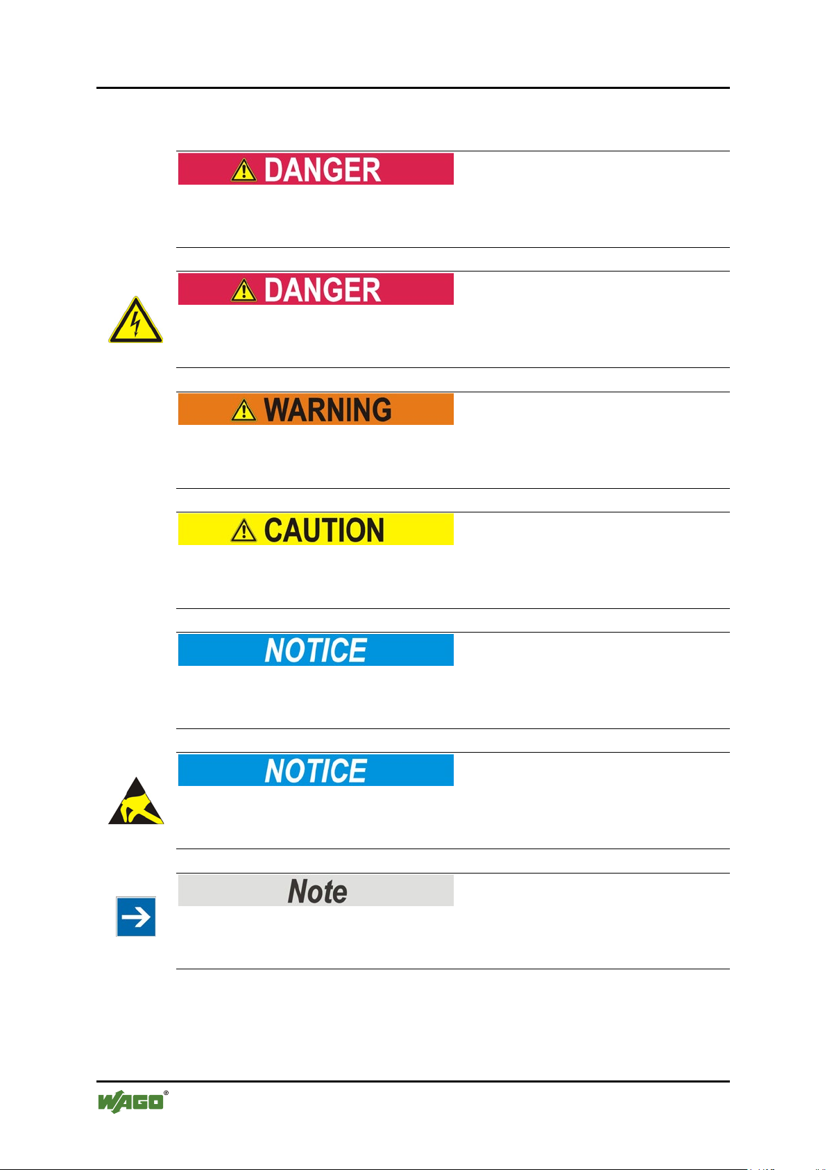
1.3 Symbols
Personal Injury!
Indicates a high-risk, imminently hazardous situation which, if not avoided, will
result in death or serious injury.
Personal Injury Caused by Electric Current!
Indicates a high-risk, imminently hazardous situation which, if not avoided, will
result in death or serious injury.
Personal Injury!
Indicates a moderate-risk, potentially hazardous situation which, if not avoided,
could result in death or serious injury.
Personal Injury!
Indicates a low-risk, potentially hazardous situation which, if not avoided, may
result in minor or moderate injury.
Damage to Property!
Indicates a potentially hazardous situation which, if not avoided, may result in
damage to property.
Damage to Property Caused by Electrostatic Discharge (ESD)!
Indicates a potentially hazardous situation which, if not avoided, may result in
damage to property.
Important Note!
Indicates a potential malfunction which, if not avoided, however, will not result in
damage to property.
Manual
Version 1.1.0, valid from SW-Version 02.02.12(03)
Page 15

WAGO-I/O-SYSTEM 750 Notes about this Documentation 15
750-8206 PFC200 CS 2ETH RS CAN DPS
Additional Information:
Refers to additional information which is not an integral part of this
documentation (e.g., the Internet).
Manual
Version 1.1.0, valid from SW-Version 02.02.12(03)
Page 16
16 Notes about this Documentation WAGO-I/O-SYSTEM 750
Table 2: Number Notation
Number code
Example
Note
Decimal
100
Normal notation
Hexadecimal
0x64
C notation
Binary
'100'
'0110.0100'
In quotation marks, nibble separated with
dots (.)
Table 3: Font Conventions
Font type
Indicates
italic
Names of paths and data files are marked in italic-type.
e.g.: C:\Programme\WAGO-I/O-CHECK
Menu
Menu items are marked in bold letters.
e.g.: Save
>
A greater-than sign between two names means the selection of a
e.g.: File > New
Input
Designation of input or optional fields are marked in bold letters,
e.g.: Start of measurement range
“Value”
Input or selective values are marked in inverted commas.
e.g.: Enter the value “4 mA” under Start of measurement range.
[Button]
Pushbuttons in dialog boxes are marked with bold letters in square
e.g.: [Input]
[Key]
Keys are marked with bold letters in square brackets.
e.g.: [F5]
750-8206 PFC200 CS 2ETH RS CAN DPS
1.4 Number Notation
1.5 Font Conventions
menu item from a menu.
brackets.
Manual
Version 1.1.0, valid from SW-Version 02.02.12(03)
Page 17

WAGO-I/O-SYSTEM 750 Important Notes 17
750-8206 PFC200 CS 2ETH RS CAN DPS
2 Important Notes
This section includes an overall summary of the most important safety
requirements and notes that are mentioned in each individual section. To protect
your health and prevent damage to devices as well, it is imperative to read and
carefully follow the safety guidelines.
2.1 Legal Bases
2.1.1 Subject to Changes
WAGO Kontakttechnik GmbH & Co. KG reserves the right to provide for any
alterations or modifications that serve to increase the efficiency of technical
progress. WAGO Kontakttechnik GmbH & Co. KG owns all rights arising from
the granting of patents or from the legal protection of utility patents. Third-party
products are always mentioned without any reference to patent rights. Thus, the
existence of such rights cannot be excluded.
2.1.2 Personnel Qualifications
All sequences implemented on WAGO-I/O-SYSTEM 750 devices may only be
carried out by electrical specialists with sufficient knowledge in automation. The
specialists must be familiar with the current norms and guidelines for the devices
and automated environments.
All changes to the coupler or controller should always be carried out by qualified
personnel with sufficient skills in PLC programming.
2.1.3 Use of the WAGO-I/O-SYSTEM 750 in Compliance with Underlying Provisions
Fieldbus couplers, fieldbus controllers and I/O modules found in the modular
WAGO-I/O-SYSTEM 750 receive digital and analog signals from sensors and
transmit them to actuators or higher-level control systems. Using programmable
controllers, the signals can also be (pre-) processed.
The devices have been developed for use in an environment that meets the IP20
protection class criteria. Protection against finger injury and solid impurities up to
12.5 mm diameter is assured; protection against water damage is not ensured.
Unless otherwise specified, operation of the devices in wet and dusty
environments is prohibited.
Operating the WAGO-I/O-SYSTEM 750 devices in home applications without
further measures is only permitted if they meet the emission limits (emissions of
interference) according to EN 61000-6-3. You will find the relevant information
in the section “Device Description” > “Standards and Guidelines” in the manual
for the used fieldbus coupler/controller.
Manual
Version 1.1.0, valid from SW-Version 02.02.12(03)
Page 18

18 Important Notes WAGO-I/O-SYSTEM 750
750-8206 PFC200 CS 2ETH RS CAN DPS
Appropriate housing (per 94/9/EG) is required when operating the WAGO-I/OSYSTEM 750 in hazardous environments. Please note that a prototype test
certificate must be obtained that confirms the correct installation of the system in
a housing or switch cabinet.
2.1.4 Technical Condition of Specified Devices
The devices to be supplied ex works are equipped with hardware and software
configurations, which meet the individual application requirements. WAGO
Kontakttechnik GmbH & Co. KG will be exempted from any liability in case of
changes in hardware or software as well as to non-compliant usage of devices.
Please send your request for modified and new hardware or software
configurations directly to WAGO Kontakttechnik GmbH & Co. KG.
Manual
Version 1.1.0, valid from SW-Version 02.02.12(03)
Page 19
WAGO-I/O-SYSTEM 750 Important Notes 19
750-8206 PFC200 CS 2ETH RS CAN DPS
2.2 Safety Advice (Precautions)
For installing and operating purposes of the relevant device to your system the
following safety precautions shall be observed:
Do not work on devices while energized!
All power sources to the device shall be switched off prior to performing any
installation, repair or maintenance work.
Install the device only in appropriate housings, cabinets or in electrical
operation rooms!
The WAGO-I/O-SYSTEM 750 and its components are an open system. As such,
install the system and its components exclusively in appropriate housings,
cabinets or in electrical operation rooms. Allow access to such equipment and
fixtures to authorized, qualified staff only by means of specific keys or tools.
Do not use in telecommunication circuits!
Only use devices equipped with ETHERNET or RJ-45 connectors in LANs.
Never connect these devices with telecommunication networks.
Replace defective or damaged devices!
Replace defective or damaged device/module (e.g., in the event of deformed
contacts), since the long-term functionality of device/module involved can no
longer be ensured.
Protect the components against materials having seeping and insulating
properties!
The components are not resistant to materials having seeping and insulating
properties such as: aerosols, silicones and triglycerides (found in some hand
creams). If you cannot exclude that such materials will appear in the component
environment, then install the components in an enclosure being resistant to the
above-mentioned materials. Clean tools and materials are imperative for handling
devices/modules.
Manual
Version 1.1.0, valid from SW-Version 02.02.12(03)
Page 20
20 Important Notes WAGO-I/O-SYSTEM 750
750-8206 PFC200 CS 2ETH RS CAN DPS
Clean only with permitted materials!
Clean soiled contacts using oil-free compressed air or with ethyl alcohol and
leather cloths.
Do not use any contact spray!
Do not use any contact spray. The spray may impair contact area functionality in
connection with contamination.
Do not reverse the polarity of connection lines!
Avoid reverse polarity of data and power supply lines, as this may damage the
devices involved.
Avoid electrostatic discharge!
The devices are equipped with electronic components that may be destroyed by
electrostatic discharge when touched. Please observe the safety precautions
against electrostatic discharge per DIN EN 61340-5-1/-3. When handling the
devices, please ensure that environmental factors (personnel, work space and
packaging) are properly grounded.
Manual
Version 1.1.0, valid from SW-Version 02.02.12(03)
Page 21

WAGO-I/O-SYSTEM 750 Important Notes 21
750-8206 PFC200 CS 2ETH RS CAN DPS
2.3 Special Use Conditions for ETHERNET Devices
If not otherwise specified, ETHERNET devices are intended for use on local
networks. Please note the following when using ETHERNET devices in your
system:
• Do not connect control components and control networks to an open
network such as the Internet or an office network. WAGO recommends
putting control components and control networks behind a firewall.
• Limit physical and electronic access to all automation components to
authorized personnel only.
• Change the default passwords before first use! This will reduce the risk of
unauthorized access to your system.
• Regularly change the passwords used! This will reduce the risk of
unauthorized access to your system.
• If remote access to control components and control networks is required,
use a Virtual Private Network (VPN).
• Regularly perform threat analyses. You can check whether the measures
taken meet your security requirements.
• Use “defense-in-depth” mechanisms in your system's security configuration
to restrict the access to and control of individual products and networks.
Manual
Version 1.1.0, valid from SW-Version 02.02.12(03)
Page 22

22 Device Description WAGO-I/O-SYSTEM 750
750-8206 PFC200 CS 2ETH RS CAN DPS
3 Device Description
The controller 750-8206(PFC200 CS 2ETH RS CAN DPS) is an automation
device that can perform control tasks of a PLC. It is suitable for mounting on a
DIN rail and stands out on account of its various interfaces.
This controller can be used for applications in mechanical and systems
engineering, in the processing industry and in building technology.
You can connect all available I/O modules of the WAGO-I/O-SYSTEM 750 (750
and 753 Series) to the controller, enabling it to internally process analog and
digital signals from the automation environment, or to supply these signals to
other devices via one of the available interfaces.
Automation tasks can be executed in all IEC 61131-3-compatible languages with
the programming system CODESYS 2.3 (WAGO-I/O-PRO).
The implementation of the CODESYS task processing is optimized with real-time
extensions in order to provide maximal performance for automation tasks. For
visualization, Web visualization is also available in addition to the development
environment.
The controller provides a physical 256 Mbyte program memory (flash), a 256
Mbyte data memory (RAM) and a 128 kbyte remanent memory (retain,
NVRAM). The memory capacities may not be able to be utilized fully on account
of internal administration.
The file system on the internal memory provides 64 Mbyte for applications. Files
may also be stored on a removable memory card, or on an internal RAM disk.
The controller provides a 16 Mbyte program memory, a 64 Mbyte data memory
and a 128 kbyte remanent memory (retain and flag variables) in an integrated
NVRAM for IEC-61131-3 programming on CODESYS applications.
</dg_
Two ETHERNET interfaces and an integrated, configurable switch enable line
topology wiring for:
• In line topology with a common MAC address and IP address for both
interfaces.
• Two separate networks with a common MAC address and an IP address for
each interface.
Both of these interfaces support:
• 10Base-T / 100Base-TX
• Full/Half duplex
• Autonegotiation
• Auto-MDI(X)
Manual
Version 1.1.0, valid from SW-Version 02.02.12(03)
Page 23
WAGO-I/O-SYSTEM 750 Device Description 23
750-8206 PFC200 CS 2ETH RS CAN DPS
The following fieldbus circuits are implemented for exchange of process data:
• MODBUS TCP
• MODBUS UDP
• MODBUS RTU (via RS-232 or RS-485)
• CANopen Master/Slave
• PROFIBUS Slave
In the controller, all input signals from the sensors are combined. After connecting
the controller, all of the I/O modules on the bus node are detected and a local
process image is created from these. Analog and specialty module data is sent via
words and/or bytes; digital data is sent bit by bit.
No direct access from fieldbus to the process image for I/O modules!
Any data that is required from the I/O module process image must be explicitly
mapped in the CODESYS program to the data in the fieldbus process image and
vice versa! Direct access is not possible!
Fieldbus configuration can be performed using the CODESYS 2.3 controller
configuration.
A Web-based management system (WBM) is also available as a configuration aid.
This system includes various dynamic HTML pages from which, among other
things, information about configuration and the status of the controller can be
called up. The WBM is already stored in the device and is presented and operated
using an Internet browser. You can also save your own HTML pages in the
implemented file system, or call up programs directly.
In the controller's initial state, the installed firmware is based on Linux®, with
special real-time extensions of the RT-Preempt patch. In addition, the following
application programs are also installed on the controller, along with a number of
different auxiliary programs:
• a SNMP server/client
• a Telnet server
• a FTP, FTPS server
• a SSH server/client
• a Web server
• a NTP client
• a BootP and DHCP daemon
Manual
Version 1.1.0, valid from SW-Version 02.02.12(03)
Page 24
24 Device Description WAGO-I/O-SYSTEM 750
750-8206 PFC200 CS 2ETH RS CAN DPS
• a CODESYS Runtime Environment
Based on IEC-61131-3 programming, data processing takes place on site in the
controller. The logical process results can be output directly to the actuators or
transmitted via a connected fieldbus to the higher level controller.
Memory card is not included in the scope of delivery!
Note, the controller is delivered without memory card.
To use a memory card, you must order one separately. The controller can also be
operated without memory card expansion, the use of a memory card is optional.
</dg_
Only use recommended memory cards!
Use only the SD memory card available from WAGO (item No. 758-879/000-
001) as it is suitable for industrial applications subjected to environmental
extremes and was developed for use in the controller.
Compatibility with other commercially available storage media cannot be
guaranteed.
Manual
Version 1.1.0, valid from SW-Version 02.02.12(03)
Page 25

WAGO-I/O-SYSTEM 750 Device Description 25
Table 4:Legend for figure “Device view”
Item
Description
See section
1
Marking Options (Mini-WSB)
---
“Indicating elements” >
supply”
“Connections” > “Data
contacts/Internal data bus”
CAGE CLAMP® Connections for Power
Supply
“Connections” > “CAGE
CLAMP® connections”
5
Slot for memory card
“Memory card slot”
Power contacts for power supply of
down-circuit I/O modules
“Connections” > “Power
contacts/ Field-side supply”
“Mounting” > “Inserting and
Removing Device”
“Connections” > “Service
interface”
“Operating elements” >
“Mode selector switch”
“Connections” > “Network
X1, X2”
750-8206 PFC200 CS 2ETH RS CAN DPS
3.1 View
Figure 1: View of device
2 LED Indicators – Power Supply
“Indicating element power
3 Data contacts
4
6
7 Releasing strap
8 Service Interface (behind the flap)
9 Mode selector switch
10 ETHERNET Connections
Manual
Version 1.1.0, valid from SW-Version 02.02.12(03)
connections ETHERNET –
Page 26

26 Device Description WAGO-I/O-SYSTEM 750
“Mounting” > “Inserting and
Removing Device”
“Connections” >
Fieldbus Connection”
“Connections” > “CANopen
– X4 Fieldbus Connection”
“Connections” >
232/RS-485 – X3”
“Indicating elements” >
Fieldbus/System”
“Operating elements” >
“Reset button”
750-8206 PFC200 CS 2ETH RS CAN DPS
11 Safe Locking Feature
12 Fieldbus Connection – PROFIBUS
13 Fieldbus Connection – CANopen
14 Serial interface
15 LED Indicators – System
16 Reset button (in hole)
“PROFIBUS DP – X5
“Communication port RS-
“Indicating elements
Manual
Version 1.1.0, valid from SW-Version 02.02.12(03)
Page 27
WAGO-I/O-SYSTEM 750 Device Description 27
750-8206 PFC200 CS 2ETH RS CAN DPS
3.2 Connectors
3.2.1 Data Contacts/Internal Bus
Do not place the I/O modules on the gold spring contacts!
Do not place the I/O modules on the gold spring contacts in order to avoid soiling
or scratching!
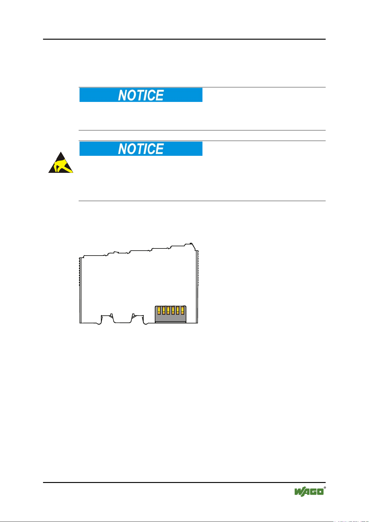
Ensure that the environment is well grounded!
The devices are equipped with electronic components that may be destroyed by
electrostatic discharge. When handling the devices, ensure that the environment
(persons, workplace and packing) is well grounded. Avoid touching conductive
components, e.g. data contacts.
Communication between the controller and the I/O modules and system power
supply for the I/O modules is provided via the internal data bus, which consists of
6 data contacts designed as self-cleaning gold spring contacts.
Figure 2: Data contacts
Manual
Version 1.1.0, valid from SW-Version 02.02.12(03)
Page 28
28 Device Description WAGO-I/O-SYSTEM 750
Table 5: Legend for Figure “Power Jumper Contacts”
Contact
Type
Function
Potential transmission (UV)
for field supply
Potential transmission (0 V)
for field supply
Potential transmission (ground)
for field supply
750-8206 PFC200 CS 2ETH RS CAN DPS
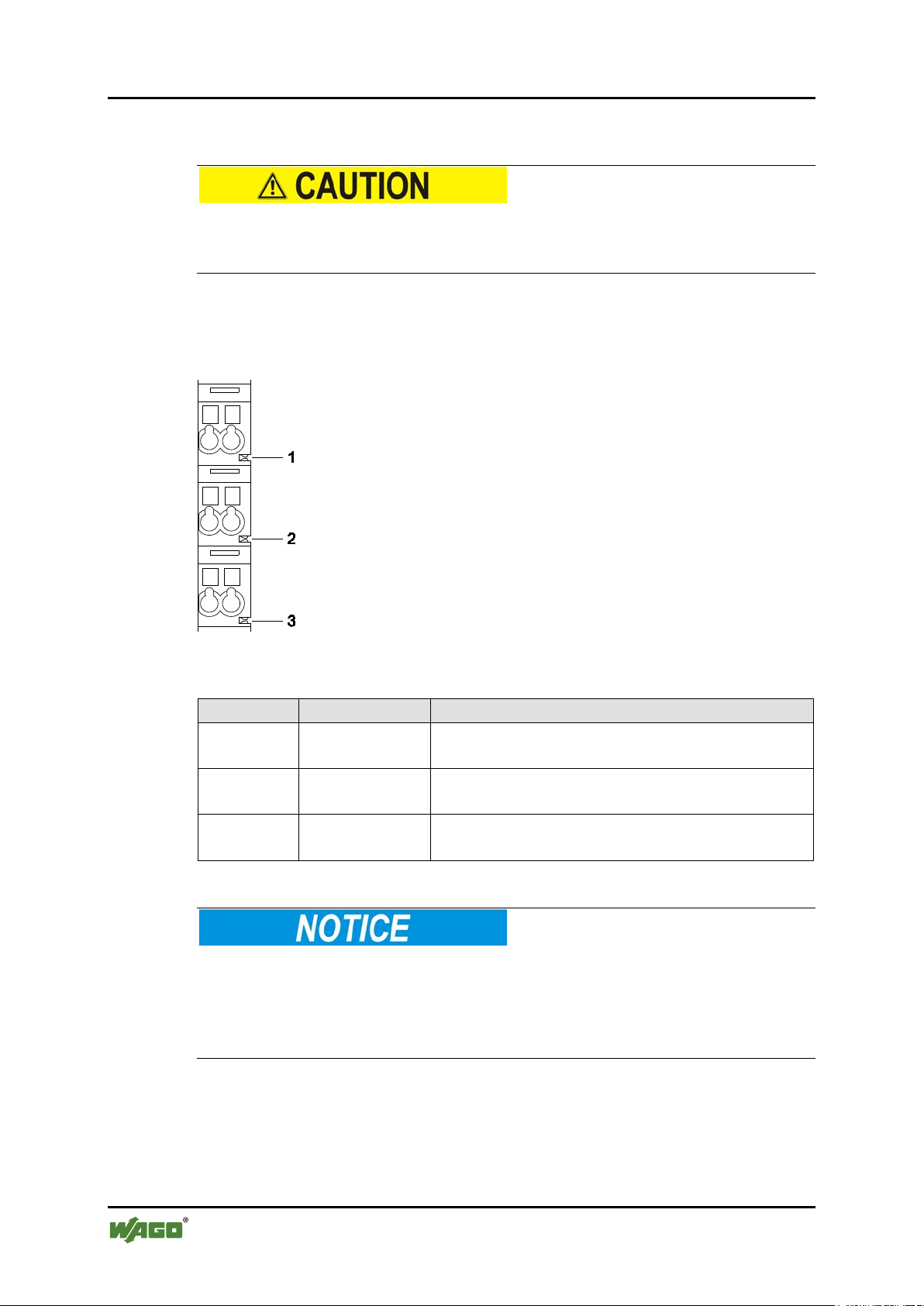
3.2.2 Power Jumper Contacts/Field Supply
Risk of injury due to sharp-edged blade contacts!
The blade contacts are sharp-edged. Handle the I/O module carefully to prevent
injury.
The controller 750-8206is equipped with 3 self-cleaning power contacts for
transferring of the field-side power supply to down-circuit I/O modules. These
contacts are designed as spring contacts.
Figure 3: Power Jumper Contacts
1 Spring contact
2 Spring contact
3 Spring contact
Do not exceed maximum current via power jumper contacts!
The maximum current to flow through the power jumper contacts is 10 A.
Greater currents can damage the contacts.
When configuring your system, ensure that this current is not exceeded. If
exceeded, insert an additional supply module.
Manual
Version 1.1.0, valid from SW-Version 02.02.12(03)
Page 29
WAGO-I/O-SYSTEM 750 Device Description 29
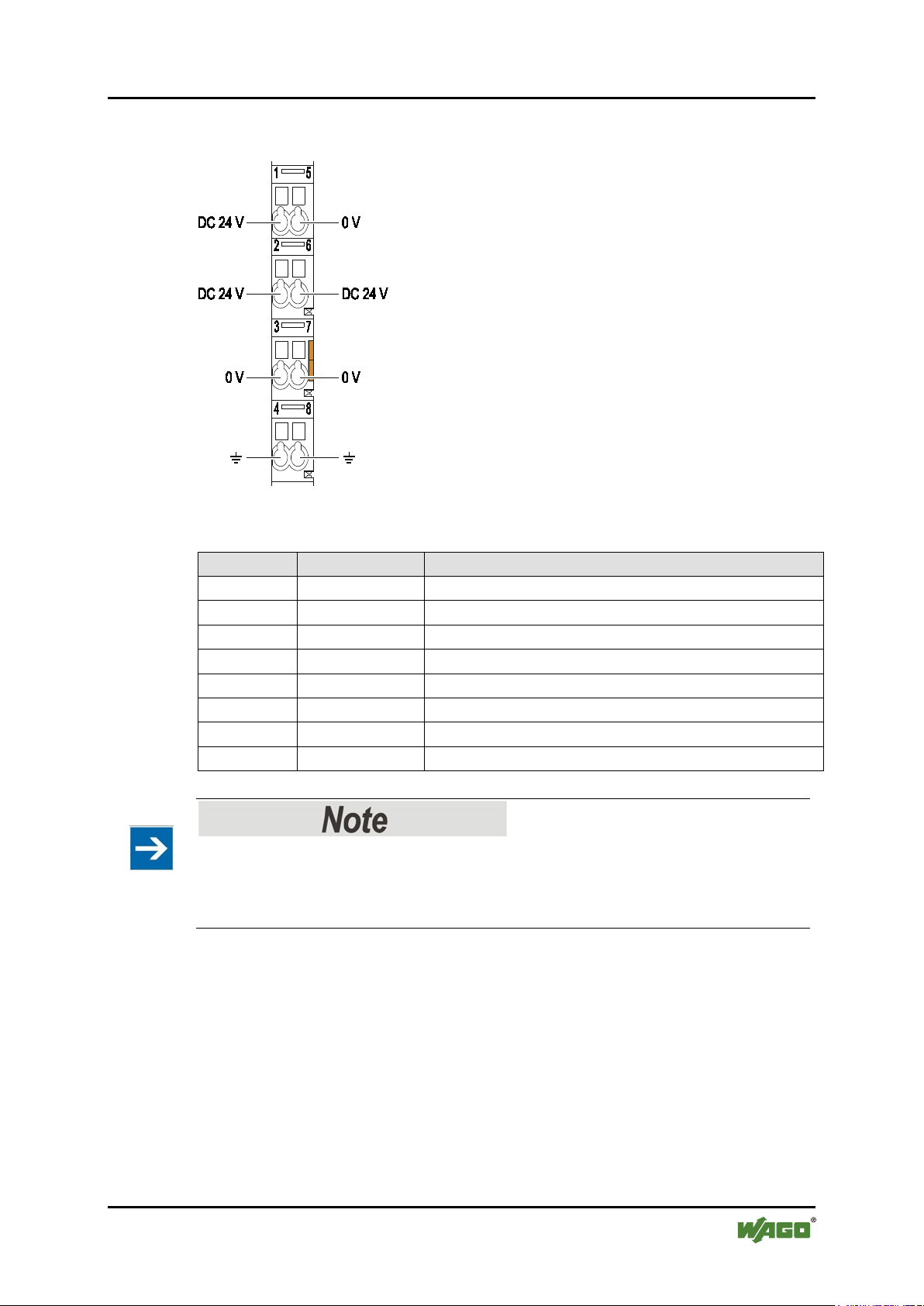
Table 6: Legend for figure “CAGE CLAMP® connections”
Contact
Description
Description
1
24 V
System power supply voltage +24 V
2
+
Field-side power supply voltage UV
3
-
Field-side power supply voltage 0 V
4
Ground
Field-side power supply voltage, ground
5
0 V
System power supply voltage 0 V
6
+
Field-side power supply voltage UV
7
-
Field-side power supply voltage 0 V
8
Ground
Field-side power supply voltage, ground
750-8206 PFC200 CS 2ETH RS CAN DPS
3.2.3 CAGE CLAMP® Connectors
Figure 4: CAGE CLAMP
®
connections
</dg_
Observe supplementary power supply regulations for use in shipbuilding!
Observe supplementary power supply regulations for shipbuilding and the supply
voltage in Section “Connect Devices” > … > “Supplementary Power Supply
Regulations”!
Manual
Version 1.1.0, valid from SW-Version 02.02.12(03)
Page 30
30 Device Description WAGO-I/O-SYSTEM 750
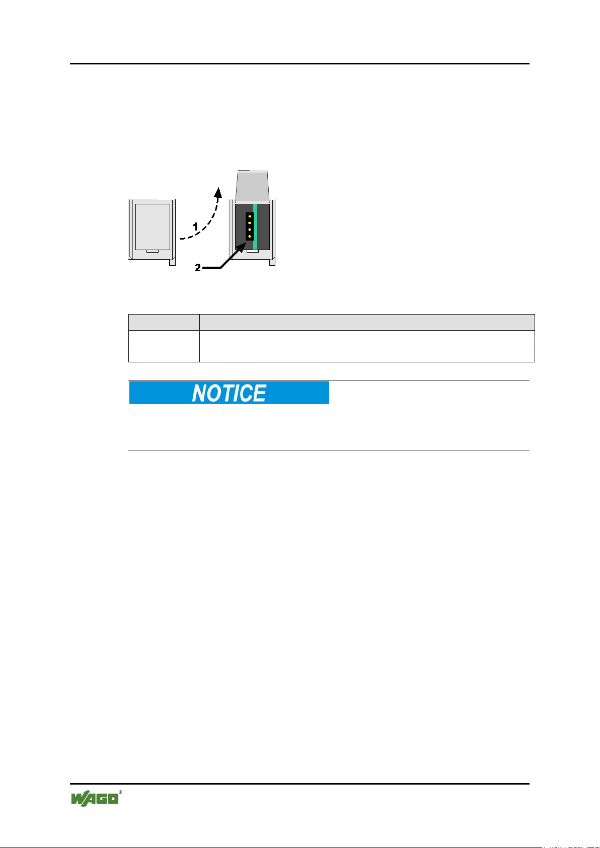
Table 7: Service interface
Number
Description
1
Open flap
2
Service interface
750-8206 PFC200 CS 2ETH RS CAN DPS
3.2.4 Service Interface
The service interface is located behind the flap.
The Service interface is used for communication with WAGO-I/O-CHECK and
WAGO-I/O-PRO and for firmware download.
Figure 5: Service interface, (closed and open flap)
Device must be de-energized!
To prevent damage to the device, unplug and plug in the communication cable
only when the device is de-energized!
The connection to the 4-pin header under the cover flap can be realized via the
communication cables with the item numbers750-920 and 750-923 or via the
WAGO radio adapter with the item number 750-921.
Manual
Version 1.1.0, valid from SW-Version 02.02.12(03)
Page 31

WAGO-I/O-SYSTEM 750 Device Description 31
Table 8: Legend for Figure "Network Connections – X1, X2"
Contact
Signal
Description
1
TD +
Transmit Data +
2
TD -
Transmit Data -
3
RD +
Receive Data +
4
NC
Not assigned
5
NC
Not assigned
6
RD -
Receive Data -
7
NC
Not assigned
8
NC
Not assigned
750-8206 PFC200 CS 2ETH RS CAN DPS
3.2.5 Network Connections – X1, X2
Figure 6: Network connections – X1, X2
Manual
Version 1.1.0, valid from SW-Version 02.02.12(03)
Page 32

32 Device Description WAGO-I/O-SYSTEM 750
Table 9: Key for the “RS-232/RS-485 – X3 communication connection” figure
RS-232
RS-485
Signal
Description
Signal
Description
1
NC
Not assigned
NC
Not assigned
2
RxD
Receive Data
NC
Not assigned
3
TxD
Transmit Data
RxD/TxD-P
Receive/transmit data +
4
NC
Not assigned
NC
Not assigned
5
FB_GND
Ground
FB_GND
Ground
6
NC
Not assigned
FB_5V
Power Supply
7
RTS
Request to send
NC
Not assigned
8
CTS
Clear to send
RxD/TxD-N
Receive/transmit data -
9
NC
Not assigned
NC
Not assigned
Enclosure
Shield
Shielding
Shield
Shielding
750-8206 PFC200 CS 2ETH RS CAN DPS
Kommunikati ons ansc hlus s
3.2.6 RS-232/RS-485 – X3 Communication Connection
Figure 7: RS-232/RS-485 – X3 communication connection
Contact
Incorrect parameterization can damage the communication partners!
The voltage levels are -12 V and +12 V for RS-232, and -5 V and +5 V for RS-
485.
If the controller interfaces differ from those of the communication partners (RS232 <> RS-485 or RS-485 <> RS-232), this may damage the interface of the
communication partner.
Therefore, always ensure that the controller interface matches those of its
communication partners when configuring these items!
DC/DC converters and optocouplers in the fieldbus interface electrically isolate
the fieldbus system and the electronics.
Manual
Version 1.1.0, valid from SW-Version 02.02.12(03)
Page 33

WAGO-I/O-SYSTEM 750 Device Description 33
Table 10: Function of RS-232 signals for DTE/DCE
Data Direction
DTE
DCE
2
RxD
Input
Output
3
TxD
Output
Input
5
FB_GND
---
---
7
RTS
Output
Input
8
CTS
Input
Output
750-8206 PFC200 CS 2ETH RS CAN DPS
3.2.6.1 Operating as an RS-232 Interface
Depending on the device type DTE (e.g., PC) or DCE (e.g., PFC, modem), the
RS-232 signals have different data directions.
Contact Signal
For a DTE-to-DCE connection, the signals are connected directly (1:1).
Figure 8: Termination with DTE-DCE connection (1:1)
For a DTE-to-DTE connection, the signal connections are crossed.
Figure 9: Termination with DTE-DTE connection (cross-over)
Manual
Version 1.1.0, valid from SW-Version 02.02.12(03)
Page 34

34 Device Description WAGO-I/O-SYSTEM 750
750-8206 PFC200 CS 2ETH RS CAN DPS
3.2.6.2 Operating as an RS-485 Interface
To minimize reflection at the end of the line, the RS-485 line must be terminated
at both ends by a cable termination. If required, one pull-up or pull-down resistor
may be used. These resistors ensure a defined level on the bus when no subscriber
is active, i.e., when all subscribers are in “Tri-state”.
Attention — bus termination!
The RS-485 MODBUS bus segment must be terminated at both ends!
No more than two terminations per bus segment may be used!
Terminations may not be used in stub and branch lines!
Operation without proper termination of the RS-485 MODBUS network may
result in transmission errors.
Figure 10: RS-485 bus termination
Manual
Version 1.1.0, valid from SW-Version 02.02.12(03)
Page 35

WAGO-I/O-SYSTEM 750 Device Description 35
Table 11: Legend for Figure “CANopen – X4 Fieldbus Connection”
Contact
Signal
Description
1
-
Not used
2
CAN_L
CAN Signal Low
3
GND
Ground
4
-
Not used
5
Drain Shield
Shield termination
6
-
Not used
7
CAN_H
CAN Signal High
8
-
Not used
9
CAN_V+
Not used
750-8206 PFC200 CS 2ETH RS CAN DPS
3.2.7 CANopen – X4 Fieldbus Connection
Figure 11: CANopen – X4 fieldbus connection
DC/DC converters and optocouplers in the fieldbus interface provide electrical
isolation between the CANopen bus system and the electronics.
The cable shield must be applied to the CAN shield. This is terminated to ground
in devices with 1 MΩ (DIN rail contact). A low-impedance connection of the
shielding to ground is possible only from the outside (e.g., by a supply module).
We recommend using central ground contacts for the entire CANopen bus line
shielding.
To minimize reflection at the end of the line, the CANopen line must be
terminated at both ends by a cable termination.
Attention - bus termination!
The CANopen bus segment must be terminated at both ends!
No more than 2 terminations per bus segment may be used!
Terminations may not be used in stub and branch lines!
Operation without proper termination of the CANopen network may result in
transmission errors.
Manual
Version 1.1.0, valid from SW-Version 02.02.12(03)
Page 36

36 Device Description WAGO-I/O-SYSTEM 750
750-8206 PFC200 CS 2ETH RS CAN DPS
Observe permissible resistor power loss!
For normal operation, 1/4Watt resistors are sufficient. In the event of a short
circuit (24V power supply to a bus line), the resistor is subjected to a power loss
of (short-circuit output current from transceiver * power supply voltage). The
resistor must be designed to withstand this power loss level.
Figure 12: CANopen standard bus termination
Manual
Version 1.1.0, valid from SW-Version 02.02.12(03)
Page 37

WAGO-I/O-SYSTEM 750 Device Description 37
Table 12: Legend for Figure “PROFIBUS DP – X5 Fieldbus Connection”
Contact
Signal
Description
1
NC
Not assigned
2
NC
Not assigned
3
PB+
Receive/transmit data +
4
NC
Not assigned
5
PB_GND
Ground
6
PB_+5V
Power supply
7
NC
Not assigned
8
PB–
Receive/transmit data -
9
NC
Not assigned
750-8206 PFC200 CS 2ETH RS CAN DPS
3.2.8 PROFIBUS DP – X5 Fieldbus Connection
Figure 13: PROFIBUS DP – X5 fieldbus connection
DC/DC converters and transmitters in the fieldbus interface provide electrical
isolation between the PROFIBUS system and the electronics.
The PROFIBUS segment must be terminated at both ends with cable terminations
in line with the PROFIBUS standard. The termination is passive and is supplied
by the bus subscribers and ensures a defined level on the bus when no subscriber
is active, i.e., when all subscribers are in “Tri-state”.
Attention - bus termination!
The bus segment must be terminated at both ends!
No more than 2 terminations per bus segment may be used!
At least 1 of the two terminations must be supplied by the bus subscriber!
Operation without proper termination of the PROFIBUS network may result in
transmission errors.
Manual
Version 1.1.0, valid from SW-Version 02.02.12(03)
Page 38

38 Device Description WAGO-I/O-SYSTEM 750
750-8206 PFC200 CS 2ETH RS CAN DPS
Figure 14: PROFIBUS line termination based on EN 50170
Manual
Version 1.1.0, valid from SW-Version 02.02.12(03)
Page 39

WAGO-I/O-SYSTEM 750 Device Description 39
Table 13: Legend for Figure “Power Supply Indicating Elements”"
Description
Color
Description
A
Green/off
Status of system power supply voltage
B
Green/off
Status of field-side power supply voltage
750-8206 PFC200 CS 2ETH RS CAN DPS
3.3 Display Elements
3.3.1 Power Supply Indicating Elements
Figure 15: Power supply indicating elements
Manual
Version 1.1.0, valid from SW-Version 02.02.12(03)
Page 40

40 Device Description WAGO-I/O-SYSTEM 750
Table 14: Legend for figure “Fieldbus/System Indicating Elements”
Description
Color
Description
Red/Green/
Orange/Off
Red/Green/
Orange/Off
Red/Green/
Orange/Off
CG
Without function
NS
Without function
Red/Green/
Orange/Off
Red/Green/
Orange/Off
Red/Green/
Orange/Off
User LED 4,
“WagoLibLed.lib” library.
User LED 3,
“WagoLibLed.lib” library.
User LED 2,
“WagoLibLed.lib” library.
User LED 1,
“WagoLibLed.lib” library.
750-8206 PFC200 CS 2ETH RS CAN DPS
3.3.2 Fieldbus/System Indicating Elements
Figure 16: Indicating elements for fieldbus/system
SYS
RUN
I/O
CAN
BF
DIA
U4
U3
Red/Green/
Orange/Off
Red/Green/
Orange/Off
System status
PLC program status
Internal data bus status
CANopen status
PROFIBUS status
PROFIBUS Diagnostics
programmable using the function blocks of the
programmable using the function blocks of the
U2
U1
Red/Green/
Orange/Off
Red/Green/
Orange/Off
Manual
Version 1.1.0, valid from SW-Version 02.02.12(03)
programmable using the function blocks of the
programmable using the function blocks of the
Page 41

WAGO-I/O-SYSTEM 750 Device Description 41
Table 15: Legend for figure “Indicating Elements, memory card slot”
Description
Color
Description
SD
Yellow/Off
Memory card status
750-8206 PFC200 CS 2ETH RS CAN DPS
3.3.3 Memory Card Indicating Elements
Figure 17: Indicating elements, memory card slot
Manual
Version 1.1.0, valid from SW-Version 02.02.12(03)
Page 42

42 Device Description WAGO-I/O-SYSTEM 750
Table 16: Legend for figure “Indicating elements, RJ-45 jacks”
Description
Color
Description
LNK
Green/Off
ETHERNET connection status
ACT
Yellow/Off
ETHERNET data exchange
750-8206 PFC200 CS 2ETH RS CAN DPS
3.3.4 Network Indicating Elements
Figure 18: Indicating elements, RJ-45 jacks
Manual
Version 1.1.0, valid from SW-Version 02.02.12(03)
Page 43

WAGO-I/O-SYSTEM 750 Device Description 43
Table 17: Mode selector switch
Item
Activation
Function
Normal mode
CODESYS 2 application runs.
Stop
CODESYS 2 application stopped.
Reset warm start or
“Starting” > “Initiating Reset Functions”)
750-8206 PFC200 CS 2ETH RS CAN DPS
3.4 Operating Elements
3.4.1 Operating Mode Switch
Figure 19: Mode selector switch
</dg_
RUN Latching
STOP Latching
RESET Spring-return
</dg_
Other functions can also be initiated using the reset button.
Reset cold start
(based on the duration of activation, see Section
Manual
Version 1.1.0, valid from SW-Version 02.02.12(03)
Page 44

44 Device Description WAGO-I/O-SYSTEM 750
750-8206 PFC200 CS 2ETH RS CAN DPS
3.4.2 Reset Button
Figure 20: Reset button
The Reset button can be actuated using a suitable object (e.g., pen) through a hole
in the enclosure.
Depending on the position of the mode selector switch, the Reset button can be
used to initiate different functions: Software reset, factory reset or fixed IP
address.
Information about these functions are given in the Section “Starting” > “Initiating
Reset Functions”.
Manual
Version 1.1.0, valid from SW-Version 02.02.12(03)
Page 45

WAGO-I/O-SYSTEM 750 Device Description 45
750-8206 PFC200 CS 2ETH RS CAN DPS
3.5 Slot for Memory Card
Figure 21: Memory card slot
The memory card is locked in the enclosure by a push/push mechanism. Inserting
and removing the card is described in the Section “Service” > “Inserting and
Removing the Memory Card”.
The memory card is protected by a cover flap, which can also be sealed.
Memory card is not included in the scope of delivery!
Note, the controller is delivered without memory card.
To use a memory card, you must order one separately. The controller can also be
operated without memory card expansion, the use of a memory card is optional.
</dg_
Only use recommended memory cards!
Use only the SD memory card available from WAGO (item No. 758-879/000-
001) as it is suitable for industrial applications subjected to environmental
extremes and was developed for use in the controller.
Compatibility with other commercially available storage media cannot be
guaranteed.
Manual
Version 1.1.0, valid from SW-Version 02.02.12(03)
Page 46

46 Device Description WAGO-I/O-SYSTEM 750
750-8206 PFC200 CS 2ETH RS CAN DPS
3.6 Schematic Diagram
Figure 22: Schematic diagram
Manual
Version 1.1.0, valid from SW-Version 02.02.12(03)
Page 47

WAGO-I/O-SYSTEM 750 Device Description 47
Table 18: Technical Data − Device Data
Width
112 mm
Height (from upper edge of DIN 35 rail)
65 mm
Length
100 mm
Weight
250 g
Table 19: Technical Data – System Data
CPU
Cortex A8, 600 MHz
Operating System
Real-time Linux® 3.6 (with RT
Preemption Patch)
Main memory (RAM)
256 MB
Internal memory (flash)
256 MB
Non-volatile memory (Retain,
NVRAM)
128 KB
Memory card slot
Push-push mechanism, sealing cover lid
Type of memory card
SD and SDHC up to 32 Gbytes
879/000-001 memory card.)
Table 20: Technical Data – Power Supply
Power supply
24 VDC (-25 % … +30 %)
Max. input current (24 V)
550 mA
Total current for I/O modules (5V)
1700 mA
Isolation
500 V system/supply
Table 21: Technical data – Clock
Drift - system clock (25 °C)
20 ppm
Drift - RTC (25 °C)
3 ppm
Buffer time RTC
30 days
750-8206 PFC200 CS 2ETH RS CAN DPS
3.7 Technical Data
3.7.1 Device Data
</dg_
3.7.2 System Data
3.7.3 Power supply
(All guaranteed properties are valid only
in connection with the WAGO 758-
</dg_
3.7.4 Clock
Manual
Version 1.1.0, valid from SW-Version 02.02.12(03)
Page 48

48 Device Description WAGO-I/O-SYSTEM 750
Table 22: Technical Data – Programming
Programming
WAGO-I/O-PRO V2.3
IEC 61131-3
IL, LD, FBD, ST, FC
Program memory (Flash)
16 MB
Data memory (RAM)
64 MB
Non-volatile memory (Retain + Flag,
NVRAM)
128 KB
Table 23: Technical Data – Internal Data Bus
Number of I/O modules (per node)
64
with bus extension
250
Input and output process image (max.)
1000 words
Table 24: Technical Data – ETHERNET
ETHERNET
2 x RJ-45 (switched or separated mode)
Transmission medium
Twisted Pair S-UTP, 100 Ω, Cat 5,
100 m maximum cable length
Baud rate
10/100 Mbit/s; 10Base-T/100Base-TX
Protocols
DHCP, DNS, SNTP, FTP, FTPS,
MODBUS (TCP, UDP)
MODBUS input and output process
1000 words,
"Flag Area")
Table 25: Technical Data – CANopen
CANopen input and output process
image max.
2000 words
750-8206 PFC200 CS 2ETH RS CAN DPS
3.7.5 Programming
3.7.6 Internal data bus
3.7.7 ETHERNET
image, max.
SNMP, HTTP, HTTPS, SSH,
also with MODBUS access to the flag
area (see Section "MODBUS" > … >
No direct access from fieldbus to the process image for I/O modules!
Any data that is required from the I/O module process image must be explicitly
mapped in the CODESYS program to the data in the fieldbus process image and
vice versa! Direct access is not possible!
3.7.8 CANopen
Manual
Version 1.1.0, valid from SW-Version 02.02.12(03)
Page 49

WAGO-I/O-SYSTEM 750 Device Description 49
Table 26: Technical Data – PROFIBUS
PROFIBUS input and output process
image max.
244 bytes in 80 slots
Table 27: Technical Data – Serial Interface
Interface
1 x serial interface per TIA/EIA 232 and
female connector
Protocols
MODBUS RTU
750-8206 PFC200 CS 2ETH RS CAN DPS
No direct access from fieldbus to the process image for I/O modules!
Any data that is required from the I/O module process image must be explicitly
mapped in the CODESYS program to the data in the fieldbus process image and
vice versa! Direct access is not possible!
3.7.9 PROFIBUS
No direct access from fieldbus to the process image for I/O modules!
Any data that is required from the I/O module process image must be explicitly
mapped in the CODESYS program to the data in the fieldbus process image and
vice versa! Direct access is not possible!
3.7.10 Serial interface
TIA/EIA 485 (switchable), 9-pole D-sub
Manual
Version 1.1.0, valid from SW-Version 02.02.12(03)
Page 50

50 Device Description WAGO-I/O-SYSTEM 750
Table 28: Technical Data – Field Wiring
Wire connection
CAGE CLAMP®
Cross section
0.08 mm² … 2.5 mm², AWG 28 … 14
Stripped lengths
8 mm … 9 mm / 0.33 in
Table 29: Technical Data – Power Jumper Contacts
Power jumper contacts
Spring contact, self-cleaning
Voltage drop at I
max.
< 1 V/64 modules
Table 30: Technical Data – Data Contacts
Data contacts
Slide contact, hard gold plated, selfcleaning
Table 31: Technical Data – Climatic Environmental Conditions
Operating temperature range
0 °C … 55 °C
Operating temperature range for
temperature range (750-xxx/025-xxx)
-20 °C … +60 °C
Storage temperature range
-25 °C … +85 °C
Storage temperature range for
temperature range (750-xxx/025-xxx)
-40 °C … +85 °C
Relative humidity
Max. 5 % … 95 % without condensation
Resistance to harmful substances
Acc. to IEC 60068-2-42 and
IEC 60068-2-43
Maximum pollutant concentration at
SO2 ≤ 25 ppm
H2S ≤ 10 ppm
Special conditions
Ensure that additional measures for
– ionizing radiation
750-8206 PFC200 CS 2ETH RS CAN DPS
3.7.11 Connection Type
3.7.12 Climatic Environmental Conditions
components with extended
components with extended
relative humidity < 75 %
Manual
Version 1.1.0, valid from SW-Version 02.02.12(03)
components are taken, which are used in
an environment involving:
– dust, caustic vapors or gases
Page 51

WAGO-I/O-SYSTEM 750 Device Description 51
Conformity Marking
750-8206 PFC200 CS 2ETH RS CAN DPS
3.8 Approvals
The following approvals have been granted to the controller “PFC200 CS 2ETH
RS CAN DPS” (750-8206):
CULUS
UL508
The following ship approvals have been granted to the basic version of the
controller “PFC200 CS 2ETH RS CAN DPS” (750-8206):
GL (Germanischer Lloyd) Cat. A, B, C, D (EMC 1)
3.9 Standards and Guidelines
The controller “PFC200 CS 2ETH RS CAN DPS” (750-8206) fulfills the
following EMC standards:
EMC CE-Immunity to interference acc. to EN 61000-6-2: 2005
EMC CE-Emission of interference acc. to EN 61000-6-3: 2007 + A1: 2011
Manual
Version 1.1.0, valid from SW-Version 02.02.12(03)
Page 52

52 Function Description WAGO-I/O-SYSTEM 750
750-8206 PFC200 CS 2ETH RS CAN DPS
4 Function Description
</dg_
4.1 Network Configuration
ETHERNET interfaces X1 and X2 of the controller can be operated in Switch
mode or as separate network interfaces.
Switch mode can be switched ON or OFF at run-time.
Switch mode is ON by default and during initial startup. Configuration mode is
set to “DHCP”.
For interface X1, a fixed IP address can be set.
Setting a fixed IP address has no effect on the mode previously set.
4.1.1 Operation in Switch Mode
For operation in Switch mode, the TCP/IP settings such as the IP address or
subnet mask apply for both X1 and X2.
When switching to Switch mode, the X1 settings are applied as a new common
configuration for X1 and X2.
The device is then no longer accessible via the IP address previously set for X2.
For CODESYS applications that use X2 for communication must take this into
account.
4.1.2 Operation with Separate Network Interfaces
When operating with separate network interfaces, both ETHERNET interfaces
can be configured and used separately.
Note that two interfaces still have the same MAC address. Therefore, they must
not be operated in the same network segment.
When switching to operating with separate interfaces, interface X2 is initialized
with the setting values last valid for it. The connections on the X1 interface
persist.
When operating with separate interfaces and fixed IP address, the device can still
be accessed via interface X2 via the regular IP address.
Manual
Version 1.1.0, valid from SW-Version 02.02.12(03)
Page 53

WAGO-I/O-SYSTEM 750 Mounting 53
750-8206 PFC200 CS 2ETH RS CAN DPS
5 Mounting
5.1 Installation Position
Along with horizontal and vertical installation, all other installation positions are
allowed.
Use an end stop in the case of vertical mounting!
In the case of vertical assembly, an end stop has to be mounted as an additional
safeguard against slipping.
WAGO order no. 249-116 End stop for DIN 35 rail, 6 mm wide
WAGO order no. 249-117 End stop for DIN 35 rail, 10 mm wide
5.2 Overall Configuration
The maximum total length of a fieldbus node without fieldbus coupler/controller
is 780 mm including end module. The width of the end module is 12 mm. When
assembled, the I/O modules have a maximum length of 768 mm.
Examples:
• 64 I/O modules with a 12 mm width can be connected to a fieldbus
coupler/controller.
• 32 I/O modules with a 24 mm width can be connected to a fieldbus
coupler/controller.
Exception:
The number of connected I/O modules also depends on the type of fieldbus
coupler/controller is used. For example, the maximum number of stackable I/O
modules on one PROFIBUS DP/V1 fieldbus coupler/controller is 63 with no
passive I/O modules and end module.
Observe maximum total length of a fieldbus node!
The maximum total length of a fieldbus node without fieldbus coupler/controller
and without using a 750-628 I/O Module (coupler module for internal data bus
extension) may not exceed 780 mm.
Also note the limitations of individual fieldbus couplers/controllers.
Manual
Version 1.1.0, valid from SW-Version 02.02.12(03)
Page 54

54 Mounting WAGO-I/O-SYSTEM 750
750-8206 PFC200 CS 2ETH RS CAN DPS
Increase the total length using a coupler module for internal data bus
extension!
You can increase the total length of a fieldbus node by using a 750-628 I/O
Module (coupler module for internal data bus extension). For such a
configuration, attach a 750-627 I/O Module (end module for internal data bus
extension) after the last I/O module of a module assembly. Use an RJ-45 patch
cable to connect the I/O module to the coupler module for internal data bus
extension of another module block.
This allows you to segment a fieldbus node into a maximum of 11 blocks with
maximum of 10 I/O modules for internal data bus extension.
The maximum cable length between two blocks is five meters.
More information is available in the manuals for the 750-627 and 750-628 I/O
Modules.
Manual
Version 1.1.0, valid from SW-Version 02.02.12(03)
Page 55

WAGO-I/O-SYSTEM 750 Mounting 55
750-8206 PFC200 CS 2ETH RS CAN DPS
5.3 Mounting onto Carrier Rail
5.3.1 Carrier Rail Properties
All system components can be snapped directly onto a carrier rail in accordance
with the European standard EN 50022 (DIN 35).
Do not use any third-party carrier rails without approval by WAGO!
WAGO Kontakttechnik GmbH & Co. KG supplies standardized carrier rails that
are optimal for use with the I/O system. If other carrier rails are used, then a
technical inspection and approval of the rail by WAGO Kontakttechnik GmbH &
Co. KG should take place.
Carrier rails have different mechanical and electrical properties. For the optimal
system setup on a carrier rail, certain guidelines must be observed:
• The material must be non-corrosive.
• Most components have a contact to the carrier rail to ground electro-
magnetic disturbances. In order to avoid corrosion, this tin-plated carrier rail
contact must not form a galvanic cell with the material of the carrier rail
which generates a differential voltage above 0.5 V (saline solution of 0.3 %
at 20°C).
• The carrier rail must optimally support the EMC measures integrated into
the system and the shielding of the I/O module connections.
• A sufficiently stable carrier rail should be selected and, if necessary, several
mounting points (every 20 cm) should be used in order to prevent bending
and twisting (torsion).
• The geometry of the carrier rail must not be altered in order to secure the
safe hold of the components. In particular, when shortening or mounting the
carrier rail, it must not be crushed or bent.
• The base of the I/O components extends into the profile of the carrier rail.
For carrier rails with a height of 7.5 mm, mounting points are to be riveted
under the node in the carrier rail (slotted head captive screws or blind
rivets).
• The medal springs on the bottom of the housing must have low-impedance
contact with the DIN rail (wide contact surface is possible).
Manual
Version 1.1.0, valid from SW-Version 02.02.12(03)
Page 56

56 Mounting WAGO-I/O-SYSTEM 750
Table 32: WAGO DIN Rail
Order number
Description
210-113 /-112
35 x 7.5;
1 mm;
steel yellow chromated; slotted/unslotted
210-114 /-197
35 x 15;
1.5 mm;
steel yellow chromated; slotted/unslotted
210-118
35 x 15;
2.3 mm;
steel yellow chromated; unslotted
210-198
35 x 15;
2.3 mm;
copper; unslotted
210-196
35 x 7.5;
1 mm;
aluminum; unslotted
750-8206 PFC200 CS 2ETH RS CAN DPS
5.3.2 WAGO DIN Rail
WAGO carrier rails meet the electrical and mechanical requirements shown in the
table below.
5.4 Spacing
The spacing between adjacent components, cable conduits, casing and frame sides
must be maintained for the complete fieldbus node.
Figure 23: Spacing
The spacing creates room for heat transfer, installation or wiring. The spacing to
cable conduits also prevents conducted electromagnetic interferences from
influencing the operation.
Manual
Version 1.1.0, valid from SW-Version 02.02.12(03)
Page 57

WAGO-I/O-SYSTEM 750 Mounting 57
750-8206 PFC200 CS 2ETH RS CAN DPS
5.5 Mounting Sequence
Fieldbus couplers/controllers and I/O modules of the WAGO-I/O-SYSTEM 750
are snapped directly on a carrier rail in accordance with the European standard EN
50022 (DIN 35).
The reliable positioning and connection is made using a tongue and groove
system. Due to the automatic locking, the individual devices are securely seated
on the rail after installation.
Starting with the fieldbus coupler/controller, the I/O modules are mounted
adjacent to each other according to the project design. Errors in the design of the
node in terms of the potential groups (connection via the power contacts) are
recognized, as the I/O modules with power contacts (blade contacts) cannot be
linked to I/O modules with fewer power contacts.
Risk of injury due to sharp-edged blade contacts!
The blade contacts are sharp-edged. Handle the I/O module carefully to prevent
injury.
Insert I/O modules only from the proper direction!
All I/O modules feature grooves for power jumper contacts on the right side. For
some I/O modules, the grooves are closed on the top. Therefore, I/O modules
featuring a power jumper contact on the left side cannot be snapped from the top.
This mechanical coding helps to avoid configuration errors, which may destroy
the I/O modules. Therefore, insert I/O modules only from the right and from the
top.
Don't forget the bus end module!
Always plug a bus end module 750-600 onto the end of the fieldbus node! You
must always use a bus end module at all fieldbus nodes with WAGO-I/OSYSTEM 750 fieldbus couplers/controllers to guarantee proper data transfer.
Manual
Version 1.1.0, valid from SW-Version 02.02.12(03)
Page 58

58 Mounting WAGO-I/O-SYSTEM 750
750-8206 PFC200 CS 2ETH RS CAN DPS
5.6 Inserting Devices
Perform work on devices only if they are de-energized!
Working on energized devices can damage them. Therefore, turn off the power
supply before working on the devices.
5.6.1 Inserting the Fieldbus Coupler/Controller
1. When replacing the fieldbus coupler/controller for an already available
fieldbus coupler/controller, position the new fieldbus coupler/controller so
that the tongue and groove joints to the subsequent I/O module are engaged.
2. Snap the fieldbus coupler/controller onto the carrier rail.
3. Use a screwdriver blade to turn the locking disc until the nose of the locking
disc engages behind the carrier rail (see the following figure). This prevents
the fieldbus coupler/controller from canting on the carrier rail.
With the fieldbus coupler/controller snapped in place, the electrical connections
for the data contacts and power contacts (if any) to the possible subsequent I/O
module are established.
Figure 24: Release Tab of Controller
Manual
Version 1.1.0, valid from SW-Version 02.02.12(03)
Page 59

WAGO-I/O-SYSTEM 750 Mounting 59
750-8206 PFC200 CS 2ETH RS CAN DPS
5.6.2 Inserting the I/O Module
1. Position the I/O module so that the tongue and groove joints to the fieldbus
coupler/controller or to the previous or possibly subsequent I/O module are
engaged.
Figure 25: Insert I/O Module (Example)
2. Press the I/O module into the assembly until the I/O module snaps into the
carrier rail.
Figure 26: Snap the I/O Module into Place (Example)
With the I/O module snapped in place, the electrical connections for the data
contacts and power jumper contacts (if any) to the fieldbus coupler/controller or to
the previous or possibly subsequent I/O module are established.
Manual
Version 1.1.0, valid from SW-Version 02.02.12(03)
Page 60

60 Connect Devices WAGO-I/O-SYSTEM 750
750-8206 PFC200 CS 2ETH RS CAN DPS
6 Connect Devices
6.1 Connecting a Conductor to the CAGE CLAMP®
The WAGO CAGE CLAMP® connection is appropriate for solid, stranded and
finely stranded conductors.
Only connect one conductor to each CAGE CLAMP®!
Only one conductor may be connected to each CAGE CLAMP®.
Do not connect more than one conductor at one single connection!
If more than one conductor must be routed to one connection, these must be
connected in an up-circuit wiring assembly, for example using WAGO feedthrough terminals.
Exception:
If it is unavoidable to jointly connect 2 conductors, then you must use a ferrule to
join the wires together. The following ferrules can be used:
Length: 8 mm
Nominal cross section
WAGO product: 216-103 or products with comparable properties
1. For opening the CAGE CLAMP® insert the actuating tool into the opening
above the connection.
: 1 mm2 for 2 conductors with 0.5 mm2 each
max.
2. Insert the conductor into the corresponding connection opening.
3. For closing the CAGE CLAMP® simply remove the tool. The conductor is
now clamped firmly in place.
Figure 27: Connecting a Conductor to a CAGE CLAMP
®
Manual
Version 1.1.0, valid from SW-Version 02.02.12(03)
Page 61

WAGO-I/O-SYSTEM 750 Connect Devices 61
Table 33: Filter Modules for 24 V Supply
Order No.
Name
Description
750-626
Supply Filter
Filter module for system supply and field supply
bus power supply (750-613)
750-624
Supply Filter
Filter module for the 24 V field supply
(750-602, 750-601, 750-610)
750-8206 PFC200 CS 2ETH RS CAN DPS
6.2 Power Supply Concept
6.2.1 Supplementary Power Supply Regulations
The WAGO-I/O-SYSTEM 750 can also be used in shipbuilding or offshore and
onshore areas of work (e. g. working platforms, loading plants). This is
demonstrated by complying with the standards of influential classification
companies such as Germanischer Lloyd and Lloyds Register.
Filter modules for 24 V supply are required for the certified operation of the
system.
(24 V, 0 V), i. e. for fieldbus coupler/controller and
Therefore, the following power supply concept must be absolutely complied with.
Figure 28: Power Supply Concept
Manual
Version 1.1.0, valid from SW-Version 02.02.12(03)
Page 62

62 Connect Devices WAGO-I/O-SYSTEM 750
750-8206 PFC200 CS 2ETH RS CAN DPS
Use a supply module for equipotential bonding!
Use an additional 750-601/ 602/ 610 Supply Module behind the 750-626 Filter
Module if you want to use the lower power jumper contact for equipotential
bonding, e.g., between shielded connections and require an additional tap for this
potential.
Manual
Version 1.1.0, valid from SW-Version 02.02.12(03)
Page 63

WAGO-I/O-SYSTEM 750 Commissioning 63
750-8206 PFC200 CS 2ETH RS CAN DPS
7 Commissioning
7.1 Switching On the Controller
Before switching on the controller ensure that you
• have properly installed the controller
(see section “Installation”),
• have connected all required data cables (see section “Connections”) to the
corresponding interfaces and have secured the connectors by their attached
locking screws,
• have connected the electronics and field-side power supply
(see section “Connections”),
• have mounted the end module (750-600)
(see Section “Installation”),
• have performed appropriate potential equalization at your machine/system
(see System Description for 750-xxx) and
• have performed shielding properly (see System Description for 750-xxx).
To switch on both the controller and the connected I/O modules, switch on your
power supply unit.
Starting of the controller is indicated by a brief green flashing of all LEDs. After a
few seconds the SYS LED will signal successful boot-up of the controller. The
CODESYS 2.3 runtime system is started simultaneously.
Once the entire system has been successfully started, the SYS and I/O LEDs light
up green.
If there is no executable IEC-61131-3 program stored on the controller, or if the
RUN/STOP switch is set to STOP, the RUN LED will light up red.
Manual
Version 1.1.0, valid from SW-Version 02.02.12(03)
Page 64

64 Commissioning WAGO-I/O-SYSTEM 750
750-8206 PFC200 CS 2ETH RS CAN DPS
7.2 Determining the IP Address of the Host PC
To ensure that the host PC can communicate with the controller via ETHERNET,
both devices must be located in the same subnet.
To determine the IP address of the host PC (with the Microsoft Windows®
operating system) using the MS DOS prompt, proceed as follows:
1. Open the MS DOS prompt window.
To do this, enter the command “cmd” in the input field under Start >
Execute… > Open: (Windows® XP) or Start > Search programs/files
(Windows® 7) and then click [OK] or press [Enter].
2. In the MS DOS prompt enter the command “ipconfig” and then press
[Enter].
3. The IP address, subnet mask and standard gateway, including the
appropriate parameters, are displayed.
Manual
Version 1.1.0, valid from SW-Version 02.02.12(03)
Page 65

WAGO-I/O-SYSTEM 750 Commissioning 65
Table 34: Default IP Addresses for ETHERNET Interfaces
Ethernet interface
Default setting
X1/X2
Dynamic assignment of IP address using “Dynamic Host
Configuration Protocol” (DHCP)
Table 35: Network Mask 255.255.255.0
Host PC
Subnet address range for the controller
192.168.1.2
192.168.1.3 … 192.168.1.254
750-8206 PFC200 CS 2ETH RS CAN DPS
7.3 Setting an IP Address
In the controller's initial state the following IP addresses are active for the
ETHERNET interface (Port X1 and Port X2):
Adapt IP addressing for your specific system structure to ensure that the PC and
the controller can communicate with one another using one of the available
configuration tools (WBM, “WAGO Ethernet Settings”, CBM) (see section
“Configuration”).
Example for incorporating the controller (192.168.2.17) into an existing
network:
If the IP address of your host PC is 192.168.1.2, for example, then the controller
must be on the same subnet. That is, with the net mask 255.255.255.0, the first
three digits of the controller must match those of your PC. This yields the
following address range for the controller:
Manual
Version 1.1.0, valid from SW-Version 02.02.12(03)
Page 66

66 Commissioning WAGO-I/O-SYSTEM 750
750-8206 PFC200 CS 2ETH RS CAN DPS
7.3.1 Assigning an IP Address using DHCP
The PFC200 can obtain dynamic IP addresses from a server (DHCP/BootP).
In contrast to fixed IP addresses, dynamically assigned addresses are not stored
permanently. Therefore, a BootP or DHCP server must be available each time the
controller is restarted.
If an IP address has been assigned by means of DHCP (default setting), it can be
determined through the settings and the output of the specific DHCP server.
In the example figure shown here, the corresponding output of “Open DHCP” is
presented.
Figure 29: “Open DHCP”, example figure
In conjunction with the DNS server associated with DHCP, the device can be
reached using its host name.
This name consists of the prefix “PFC200-“ and the last six places of the MAC
address (in the example shown here: “00:30:DE:FF:00:5A”). The MAC address of
the device can be printed on the label on the side of the device.
The host name of the device in the example shown here is thus “PFC200FF005A”.
Manual
Version 1.1.0, valid from SW-Version 02.02.12(03)
Page 67

WAGO-I/O-SYSTEM 750 Commissioning 67
750-8206 PFC200 CS 2ETH RS CAN DPS
7.3.2 Changing an IP Address using the “CBM” Configuration Tool via the Serial Interface
Using the “CBM” configuration tool accessible on the Linux® console, you can
assign, among other things, a new IP address to the ETHERNET interfaces X1
and X2. More information about “CBM” is given in the Section “Configuration”.
Preparation:
Link a PC to the X3 serial interface using a terminal program.
1. Start the configuration tool by entering the command “cbm” on the
command line and then press [Enter].
Figure 30: CBM starting screen
2. In the Main menu use the keyboard (arrow keys or numeric keypad) to
move to and select Networking and then press [Enter].
Figure 31: CBM – Selecting “Networking”
Manual
Version 1.1.0, valid from SW-Version 02.02.12(03)
Page 68

68 Commissioning WAGO-I/O-SYSTEM 750
750-8206 PFC200 CS 2ETH RS CAN DPS
3. In the Networking menu select TCP/IP and press [Enter].
Figure 32: CBM – Selecting “TCP/IP”
4. In the menu TCP/IP select IP Address and press [Enter].
Figure 33: CBM – Selecting “IP address”
Manual
Version 1.1.0, valid from SW-Version 02.02.12(03)
Page 69

WAGO-I/O-SYSTEM 750 Commissioning 69
750-8206 PFC200 CS 2ETH RS CAN DPS
5. In the menu TCP/IP Configuration select IP Address and press [Enter].
Figure 34: CBM – Selecting the IP address
6. In the menu Change IP Address enter the new IP address and confirm by
clicking [OK]. If you want to return to the main menu without making
changes, click [Abort].
Figure 35: CBM – Entering a new IP address
Manual
Version 1.1.0, valid from SW-Version 02.02.12(03)
Page 70

70 Commissioning WAGO-I/O-SYSTEM 750
750-8206 PFC200 CS 2ETH RS CAN DPS
7.3.3 Changing an IP Address using “WAGO Ethernet Settings”
The Microsoft Windows® application “WAGO Ethernet Settings” is a software
used to identify the controller and configure network settings.
Observe the software version!
To configure the controller use at least Version 5.4.2.3 dated July 20, 2013 in
“WAGO Ethernet Settings”!
You can use WAGO communication cables or WAGO radio adapters or even the
IP network for data communication.
1. Switch off the power supply to the controller.
2. Connect the 750-920 communication cable to the Service interface on the
controller and to a serial interface of your PC.
3. Switch the power supply to the controller on again.
4. Start the “WAGO Ethernet Settings” program.
Figure 36: "WAGO Ethernet Settings" – Starting screen
Manual
Version 1.1.0, valid from SW-Version 02.02.12(03)
Page 71

WAGO-I/O-SYSTEM 750 Commissioning 71
750-8206 PFC200 CS 2ETH RS CAN DPS
5. Click [Identify] to read in and identify the connected PFC200.
6. Select the “Network” tab:
Figure 37: “WAGO Ethernet Settings” – “Network” tab
7. To assign a fixed address, select “Static configuration” on the “Source” line
under “Input”. DHCP is normally activated as the default setting.
8. In the column “Input” enter the required IP address and, if applicable, the
address of the subnet mask and of the gateway.
9. Click on [Write] to accept the address in the PFC200. (When you click the
[Write] button “WAGO Ethernet Settings” will automatically restart your
controller. This action therefore requires about 30 seconds.)
10. You can now close “WAGO Ethernet Settings”, or make other changes
directly in the Web-based Management system as required. To do this, click
on [WBM] at the right in the window.
Manual
Version 1.1.0, valid from SW-Version 02.02.12(03)
Page 72

72 Commissioning WAGO-I/O-SYSTEM 750
750-8206 PFC200 CS 2ETH RS CAN DPS
7.4 Testing the Network Connection
Carry out a ping network function to check whether you can reach the controller
at the IP address you have assigned in the network.
1. Open the MS DOS prompt window.
To do this, enter the command “cmd” in the input field under Start >
Execute… > Open: (Windows® XP) or Start > Search programs/files
(Windows® 7) and then click [OK] or press [Enter].
2. In the MS DOS window, enter the command “ping” and the IP address of
the controller (for example, ping 192.168.1.17)and then press
[Enter].
Host entries in the ARP table!
It may also be useful to delete the current host entries in the ARP table with the
command “arp -d *” before executing the “ping” command (as administrator in
Windows® 7). This ensures that older entries will not impair the success of the
“ping” command.
3. Your PC sends out a query that is answered by the controller. This reply
appears in the MS DOS prompt window. If the error message “Timeout”
appears, the controller has not responded properly. You then need to check
your network settings.
Figure 38: Example of a function test
4. If the test is completed successfully, close the MS DOS window.
Manual
Version 1.1.0, valid from SW-Version 02.02.12(03)
Page 73

WAGO-I/O-SYSTEM 750 Commissioning 73
750-8206 PFC200 CS 2ETH RS CAN DPS
7.5 Shutdown/Restart
Switch off the power supply to shut down the controller.
To perform a controller restart press and hold the Reset ALL button for more than
7 seconds until all of the LEDs go out.
The controller then performs a restart.
As an alternative, you can switch off the controller and switch it back on again.
A controller restart is signaled by all LEDs briefly lighting up green.
Manual
Version 1.1.0, valid from SW-Version 02.02.12(03)
Page 74

74 Commissioning WAGO-I/O-SYSTEM 750
750-8206 PFC200 CS 2ETH RS CAN DPS
</dg_
7.6 Initiating Reset Functions
You can initiate various reset functions using the mode selector switch and the
Reset button (RST).
7.6.1 Warm Start Reset
The CODESYS 2 application is reset on a warm start reset.
This corresponds to the CODESYS 2 IDE command “Reset”.
</dg_
To perform a warm start reset, set the mode selector switch to "Reset" and hold it
there for two to seven seconds.
Execution of the reset is signaled by the red “RUN LED” briefly going out when
the mode selector switch is released.
7.6.2 Cold Start Reset
On a cold start reset the CODESYS 2 application is reset and the memory
containing the retain variables is cleared.
This corresponds to the CODESYS 2 IDE command “Reset (Cold)”.
</dg_
To perform a cold start reset, set the mode selector switch to “Reset” and hold it
there for more than seven seconds.
Execution of the reset is signaled after seven seconds by the “RUN” LED going
out for an extended period. You can then release the mode selector switch.
</dg_
7.6.3 Software Reset
The controller is restarted on a software reset.
To perform a software reset, set the mode selector switch to RUN or STOP and
then press the Reset button (RST) for one to eight seconds.
All LEDs will light up briefly in green to signal reset completion.
</dg_
7.6.4 Setting a Fixed IP Address
This procedure sets the IP address for the X1 interfaces to the fixed address
“192.168.1.17”.
When the switch is enabled, the fixed address is also used for interface X2.
When the switch is disabled, the original address setting for interface X2 is not
changed.
No reset is performed.
To make this setting, set the mode selector switch to STOP and press and hold the
Reset button (RST) for longer than eight seconds.
Execution of the setting is signaled by the “SYS” LED flashing orange.
To cancel this setting, perform a software reset or switch off the controller and
then switch it back on.
</dg_
Manual
Version 1.1.0, valid from SW-Version 02.02.12(03)
Page 75

WAGO-I/O-SYSTEM 750 Commissioning 75
750-8206 PFC200 CS 2ETH RS CAN DPS
7.6.5 Factory Reset
A factory reset restores the device to its initial state on delivery. The controller is
then restarted.
Any subsequently installed firmware functions are overwritten!
Firmware functions installed after initial controller startup are overwritten by a
factory reset, and the firmware is reset to the version marked on the device.
After factory reset, some of the functions described in this manual may no longer
be available.
To restore the current operating status, you will need:
• a backup of the currently programmed application,
• the currently installed firmware,
• the manual’s version that is applicable to the factory settings.
If you have any questions, feel free to contact our WAGO Support.
To perform a factory reset, set the mode selector switch to “RESET” and press the
Reset button (RST) for 1 … 8 seconds. Briefly release the Reset button (RST)
(< 1 second) and press it again until the “CAN” LED lights up red. If the “CAN”
LED lights up red, release the mode selector switch and the Reset button.
After the first 1 … 8 seconds, the controller reboots (all LEDs light up orange)
and after another 3 seconds, the “Factory reset” process begins. The process is
indicated by all LEDs lighting up red in succession.
Alternatively, you can also initiate a factory reset when you switch on the
controller. Hold the mode selector switch at “RESET” for at least 3 seconds when
you switch on the controller and hold the Reset button (RST) down until the
“CAN” LED lights up red. If the “CAN” LED lights up red, release the mode
selector switch and the Reset button.
Do not interrupt the reset process!
If you release the Reset button (RST) too soon (after the Reset process), the
controller switches to production mode (indicated by a green “CAN” LED). If this
happens, switch the controller off and then back on again.
Do not switch off!
Do not interrupt, i.e., switch off the controller, during the factory reset process! In
other words, do not switch off the controller while this process is in progress!
Manual
Version 1.1.0, valid from SW-Version 02.02.12(03)
Page 76

76 Commissioning WAGO-I/O-SYSTEM 750
WBM
Linux®
Web Based Management
(WBM)
Linux® console
X X X
Console Based Management
(CBM)
CODESYS
X
Telnet X X X
FTP X X X
FTPS X X X
SSH X X X
SNMP X
750-8206 PFC200 CS 2ETH RS CAN DPS
7.7 Users and Passwords
Several groups of users are provided in the controller which can be used for
various services.
Standard passwords are set for all users. We strongly recommend changing these
passwords on startup!
Change passwords
Standard passwords are documented in these instructions and therefore do not
offer adequate protection! Change the passwords to meet your particular needs.
7.7.1 Services and Users
All password-protected services and their associated users are listed in the
following table.
Service
admin
user
root
admin
user
X X
X X
SNMP user
Manual
Version 1.1.0, valid from SW-Version 02.02.12(03)
Page 77

WAGO-I/O-SYSTEM 750 Commissioning 77
Table 36: WBM Users
Users
Permissions
Default Password
admin
All (administrator)
wago
user
Supported to a limited
extent:
user
guest
Display only
---
Table 37: Linux® Users
User
Special Feature
Home Directory
Default Password
root
Super user
/root
wago
admin
CODESYS user
/home/admin
wago
user
Normal user
/home/user
user
750-8206 PFC200 CS 2ETH RS CAN DPS
7.7.2 WBM Group
WBM has its own user administration system. The users in this system are
isolated from the other user groups in the system for security reasons.
Detailed information about this is given in the Section “WBM User
Administration”.
7.7.3 Linux User Group
The Linux® users group include the actual users of the operating system, which is
likewise used by most services.
The passwords for these users must be configured through a terminal connection
via SSH/RS-232.
7.7.4 SNMP User Group
The SNMP service manages its own users. In its initial state, no users are stored in
the system.
Manual
Version 1.1.0, valid from SW-Version 02.02.12(03)
Page 78

78 Commissioning WAGO-I/O-SYSTEM 750
750-8206 PFC200 CS 2ETH RS CAN DPS
7.8 Configuration
The following methods are available for configuring the PFC200:
• Access to the Web-based management system via the PC using an Internet
browser (“Configuration using Web-Based Management (WBM)”)
• Access to the “Console-Based Management” system (CBM) via the PC
using a terminal program (via ETHERNET and/or RS-232 interface)
(“Configuration using a Terminal Program”)
• Access via the CODESYS PLC program using the WagoConfigToolLIB.lib
library (“Appendix” > “WagoConfigToolLIB.lib”)
• Access via the PC using “WAGO Ethernet Settings” (“Configuration using
'WAGO Ethernet Settings'”).
The CBM basically provides the same parameters for configuration of the
PFC200 as the WBM, except for parameters which cannot be represented in a
useful manner in a terminal window.
For an explanation of these parameters refer to the sections starting at
“'Information' Page”.
Manual
Version 1.1.0, valid from SW-Version 02.02.12(03)
Page 79

WAGO-I/O-SYSTEM 750 Commissioning 79
750-8206 PFC200 CS 2ETH RS CAN DPS
</dg_
7.8.1 Configuration using Web-Based Management (WBM)
The implemented HTML pages (from here on referred to as “pages”) for WebBased Management configure the PFC200. Proceed as follows for access the
WBM using an Internet browser:
1. Connect the PFC200 to the ETHERNET network via the ETHERNET
interface X1.
2. To access the pages, enter the controller's IP address in the address line of
your browser followed by “/wbm”, e.g., “http://192.168.1.17/wbm”. Note
that the PC and the PFC200 must be located within the same subnet (see
Section “Setting an IP Address”). If you do not know the IP address and
cannot determine it, switch the controller to the pre-set address
“192.168.1.17” using the “Fixed IP address” function (see Section “Initiate
Reset Functions” > “Set Fixed IP Address”).
If you have installed a DHCP server on your PC and would like to access WBM
through DHCP, use the other interface. You can find detailed information about
this in the section “Assigning an IP Address Using DHCP”.
Displaying the PFC200 Start Page
If the PFC200 does not display the start page, ensure that your Internet browser
settings permit bypassing the proxy server for local addresses. Also check
whether your PC is located in the same subnet as the PFC200.
Take usage by the CODESYS program into account
If the PFC200 is at capacity due to a CODESYS program, this may result in
slower processing in the WBM. As a result, timeout errors are sometimes reported
under some circumstances. It is therefore important to stop the CODESYS
application prior to performing complicated configuration using WBM.
Manual
Version 1.1.0, valid from SW-Version 02.02.12(03)
Page 80

80 Commissioning WAGO-I/O-SYSTEM 750
Table 38: User Settings in the Initial State
Users
Password
user
user
admin
wago
750-8206 PFC200 CS 2ETH RS CAN DPS
Some pages of the WBM are password protected. The first time you select an item
from the navigation bar, the password query appears:
Figure 39: Entering authentication
7.8.1.1 WBM User Administration
To allow settings to be made only by a select number of users, limit access to
WBM functions through User Administration.
Change passwords
Standard passwords are documented in these instructions and therefore do not
offer adequate protection. Change the passwords to meet your particular needs,
see Section “'Administration - Users' Page”.
If you do not change the passwords, a warning is displayed on every requested
web page after logging in.
Figure 40: Password reminder
Manual
Version 1.1.0, valid from SW-Version 02.02.12(03)
Page 81

WAGO-I/O-SYSTEM 750 Commissioning 81
Table 39: Access Rights for WBM Pages
Navigation
WBM page
User
Information
Status Information
---
CODESYS
– Information
CODESYS Information
---
– General Configuration
CODESYS Configuration
user, admin
– WebVisu
CODESYS WebVisu
---
Networking
– Host/Domain Name
Configuration of Network Parameters
user, admin
– TCP/IP
TCP/IP Configuration
user, admin
– Ethernet
Configuration of Ethernet Parameters
user, admin
Clock
Configuration of Date and Time
user, admin
Administration
– Users
Configuration of the users for the Webbased Management
admin
– Create Image
Create bootable Image
admin
– Serial Interface
Configuration of Serial Interface RS233
admin
– Reboot
Reboot Controller
admin
Package Server
– Firmware Backup
Firmware Backup
admin
– Firmware Restore
Firmware Restore
admin
– System Partition
System Partition
admin
Mass Storage
Mass Storage
admin
Software Uploads
Software Uploads
admin
Ports and Services
– Network Services
Configuration of Network Services
user, admin
– NTP Client
Configuration of NTP Client
user, admin
– CODESYS Services
Configuration of the CODESYS Services
user, admin
– SSH
SSH Client Settings
user, admin
– TFTP
TFTP Server
user, admin
SNMP
– General Configuration
Configuration of SNMP parameter general
admin
– v1/v2c
Configuration of SNMP parameter v1/v2c
admin
– v3
Configuration of SNMP v3 Users
admin
Diagnostic
Diagnostic Information
---
PROFIBUS DP
Configuration of PROFIBUS DP Slave
user, admin
750-8206 PFC200 CS 2ETH RS CAN DPS
Observe access rights
Users in WBM are authorized exclusively for access to Web pages. User
administration for controller applications is configured separately.
Access to the WBM pages is as follows:
Manual
Version 1.1.0, valid from SW-Version 02.02.12(03)
Page 82

82 Commissioning WAGO-I/O-SYSTEM 750
750-8206 PFC200 CS 2ETH RS CAN DPS
7.8.1.2 General Information about the Page
Figure 41: WBM browser window (example)
The device name is displayed in the header of the browser window.
The navigation tree is shown at the left edge of the browser window. You can use
this navigation tree to go to the individual pages and, where provided, subpages
included in these pages.
A status area with the following elements is displayed at the right edge:
Figure 42: WBM status information (example)
• WBM status:
Here, you can recognize whether the WBM is currently communicating with
the device in the background, i.e., one or more queries have been sent and
the browser is waiting on a response. Movement is then visible in the
graphic. This occurs when data are read on initial call-up of the page, when
Manual
Version 1.1.0, valid from SW-Version 02.02.12(03)
Page 83

WAGO-I/O-SYSTEM 750 Commissioning 83
750-8206 PFC200 CS 2ETH RS CAN DPS
the user has sent off a change form or when data is reloaded automatically
in cycles, e.g., the contents of the status area.
• Local Time:
Local time on the device
• Local Date:
Local date on the device
• PLC Switch:
Setting of the mode selector switch
• LEDs:
Here, the the status of the device LEDs is indicated. All of the LEDs are
symbolized by a diagram and are labeled with their particular designation
(e.g., SYS, RUN, etc.). The following colors may be used:
- gray:
LED is off
- full color (green, red, yellow, orange):
The LED is activated in the particular color
- half color:
The LED is flashing in the corresponding color. The other half of the
surface is then either gray or also colored. The latter case indicates that the
LED is flashing sequentially in different colors.
A tool tip containing more detailed information opens as long as the cursor
is positioned over an LED. The text that is displayed also contains the
message that put the LED into its current status. The time of the message is
also shown.
The statuses displayed in the WBM will not always correspond at the
precise time to those on the PFC200. Data has a runtime during transmission
and can only be queried at a certain interval. The time period between two
queries is 30 seconds.
The contents of the individual pages and sub-pages are explained in the following
sections.
Manual
Version 1.1.0, valid from SW-Version 02.02.12(03)
Page 84

84 Commissioning WAGO-I/O-SYSTEM 750
Table 40: WBM “Status Information” page – “Controller Details” group
Parameters
Explanation
Product Description
Controller identification
Order Number
Item number of the controller
Notification that the CODESYS runtime system is
available
Firmware Revision
Firmware status
Table 41: WBM “Status Information” page – “Network Details (Xn)” group(s)
Parameters
Explanation
Status of the ETHERNET interface
(enabled/disabled)
Mac Address
MAC address identifies and addresses the controller
IP Address
Current IP address of the controller
Subnet Mask
Current subnet mask of the controller
750-8206 PFC200 CS 2ETH RS CAN DPS
</dg_
7.8.1.3 “Status Information” Page
The following tables explain the parameters listed on this page:
7.8.1.3.1 “Controller Details” Group
License Information
7.8.1.3.2 “Network Details (Xn)” Group(s)
If the switch is enabled, one group (“Network Details”) is shown for both
connections.
If the switch is disabled, one group (“Network Details X1” / “Network Details
X2”) is shown for each connection.
State
Manual
Version 1.1.0, valid from SW-Version 02.02.12(03)
Page 85

WAGO-I/O-SYSTEM 750 Commissioning 85
Table 42: WBM “CODESYS Configuration” page – “General Configuration” group
Display Fields
Explanation
Select which CODESYS version you want to
activate.
None
CODESYS is not active.
2
CODESYS version 2 is active.
Select the storage medium the boot project will be
stored on.
The boot project is stored on the
memory card.
The boot project is stored in the
internal flash memory.
750-8206 PFC200 CS 2ETH RS CAN DPS
</dg_
7.8.1.4 “CODESYS Configuration” Page
The settings for the boot project created in CODESYS are shown on the
“CODESYS Configuration” page.
7.8.1.4.1 “General Configuration” Group
CODESYS Version
(Boot Device)
“Internal Flash” is not always available!
The boot project can only be stored in the internal flash memory when the
operating system has been started from the internal flash.
If the operating system has been started from the memory card, the “Internal
Flash” option is not available.
Click [Submit] to apply change. The change is effective immediately.
Restart the controller after changing this setting!
Restart the controller after changing the setting to ensure that any files still open
are switched over correctly.
Memory Card
Internal Flash
Manual
Version 1.1.0, valid from SW-Version 02.02.12(03)
Page 86

86 Commissioning WAGO-I/O-SYSTEM 750
Table 43: WBM “CODESYS – Information” page – “CODESYS” group
Display Fields
Explanation
The version of the CODESYS runtime system
fields of this group are disabled).
The version number of the CODESYS Web server is
enabled.
The operating status of CODESYS is shown. This
field is only visible when CODESYS is enabled.
STOP
PLC program is not executed.
RUN
PLC program is executed.
The number of tasks in the CODESYS program is
enabled.
Table 44: WBM “CODESYS Information” page – “Project Details” group
Display Fields
Explanation
Display of project information that the programmer
given under “Description.”
750-8206 PFC200 CS 2ETH RS CAN DPS
</dg_
7.8.1.5 “CODESYS Information” Page
All information about the PLC program created in CODESYS is provided on the
“CODESYS Information” page.
7.8.1.5.1 “CODESYS” Group
Version
Version Number
CODESYS State
Number of Tasks
7.8.1.5.2 “Project Details” Group
Date
Title
Version
Author
Description
currently active is shown (if the runtime system is
disabled, “None” is displayed and the subsequent
shown. This field is only visible when CODESYS is
shown. This field is only visible when CODESYS is
entered in the PLC program (in CODESYS under
Project > Project Information...).
The information only appears in an executed PLC
program.
Descriptive texts up to 1024 characters long are
7.8.1.5.3 "Task n" Group(s)
One dedicated group is displayed for each task when the PLC program is
executed. As a rule, only the group title is displayed with the task number, the task
name and the task ID.
Click [+] to expand the group and display the following information.
Manual
Version 1.1.0, valid from SW-Version 02.02.12(03)
Page 87

WAGO-I/O-SYSTEM 750 Commissioning 87
Table 45: WBM “CODESYS Information” page – “Task n” group(s)
Display Field
Explanation
Cycle count
Number of task cycles since system start
Cycle time (µsec)
Currently measured task cycle time
Cycle time min (µsec)
Minimum task cycle time since system start
Cycle time max (µsec)
Maximum task cycle time since system start
Cycle time avg (µsec)
Average task cycle time since system start
Status
Task status (e.g., RUN, STOP)
Mode
Task execution mode (e.g., in cycles)
Priority
Set task priority
Interval (msec)
Set task interval
750-8206 PFC200 CS 2ETH RS CAN DPS
To hide this information, click [-].
Manual
Version 1.1.0, valid from SW-Version 02.02.12(03)
Page 88

88 Commissioning WAGO-I/O-SYSTEM 750
Table 46: WBM “CODESYS WebVisu” page – “Webserver Configuration” group
Display Fields
Explanation
CODESYS Webserver
State
The status (enabled/disabled) of the CODESYS Web
server is displayed here.
Choose whether the Web-based Management or
when only entering the IP address of the controller.
Web-based
Management
The Web-based Management is
displayed.
CODESYS
WebVisu
The CODESYS Web visualization is
displayed.
750-8206 PFC200 CS 2ETH RS CAN DPS
</dg_
7.8.1.6 “CODESYS WebVisu” Page
The settings for the Web visualization created in CODESYS are shown on the
“CODESYS WebVisu” page.
7.8.1.6.1 “Webserver Configuration” Group
CODESYS Web visualization should be displayed
Default Webserver
Click [Submit] to apply change. The change is effective immediately.
In its default setting, the WBM is called up when only entering the IP address.
To update the display after switching, enter the IP address again in the address
line of the Web browser.
To display the Web visualization, the CODESYS Web server must be enabled (in
WBM under “Ports and Services” -> “CODESYS Services”) and there must be a
suitably configured CODESYS application.
Regardless of the default Web browser setting, the WBM can be called up at any
time with “http://<IP address>/wbm” and the Web visualization with “http://<IP
address>/webvisu”.
You can obtain additional information on CODESYS Web visualization in the
chapter with the same name.
Possible error messages when calling up the Web visualization
The “500 − Internal Server Error” message indicates that the CODESYS Web
server is not enabled.
A page with the header “WebVisu not available” means that no CODESYS
application has been loaded in the controller using Web visualization.
Manual
Version 1.1.0, valid from SW-Version 02.02.12(03)
Page 89

WAGO-I/O-SYSTEM 750 Commissioning 89
Table 47: WBM “Configuration of Network Parameters” page – “Hostname” group
Parameters
Explanation
If you have selected dynamic assignment of an IP
being used is displayed.
Enter the host name of the PC that will be used after
a controller restart.
Table 48: WBM “Configuration of Network Parameters” page – “Domain Name” group
Parameters
Explanation
Domain Name
Set the domain name here.
750-8206 PFC200 CS 2ETH RS CAN DPS
</dg_
7.8.1.7 “Configuration of Network Parameters” Page"
The settings for the general TCP/IP parameters are found on the “Configuration of
Network Parameters” page.
7.8.1.7.1 “Hostname” Group
Currently used
Configured
Click [Submit] to apply the change. The change becomes effective after the next
controller reboot.
7.8.1.7.2 “Domain Name” Group
Click [Submit] to apply change. The change is effective immediately.
address via DHCP, the name of the host currently
Manual
Version 1.1.0, valid from SW-Version 02.02.12(03)
Page 90

90 Commissioning WAGO-I/O-SYSTEM 750
Table 49: WBM “TCP/IP Configuration” page – “Switch Configuration” group
Parameters
Explanation
Enable or disable the switch.
Both interfaces are operated with one
IP address.
Each interface is operated with its own
IP address.
Table 50: WBM “TCP/IP Configuration” page – “IP Address (Xn)” group(s)
Parameters
Explanation
Select a static or dynamic IP address.
Static IP
Static IP addressing
DHCP
Dynamic IP addressing
BootP
Dynamic IP addressing
Here, enter a static IP address. This is active if
field.
Enter the subnet mask here. This is active if “Static
IP” is activated in the Configuration Type field.
750-8206 PFC200 CS 2ETH RS CAN DPS
</dg_
7.8.1.8 “TCP/IP Configuration” Page
The TCP/IP settings for the ETHERNET interfaces are shown on the “TCP/IP
configuration” page.
7.8.1.8.1 “Switch Configuration” Group
Interfaces
Switched
Separated
Click [Submit] to apply change. The change is effective immediately.
7.8.1.8.2 “IP Address (Xn)” Group(s)
If the switch is enabled, one group (“IP Address”) is shown for both connections.
If the switch is disabled, one group (“IP Address X1” / “IP Address X2”) is shown
for each connection.
Configuration Type
IP Address
“Static IP” is activated in the Configuration Type
Subnet Mask
Click [Submit] to apply changes. The change is effective immediately.
Manual
Version 1.1.0, valid from SW-Version 02.02.12(03)
Page 91

WAGO-I/O-SYSTEM 750 Commissioning 91
Table 51: WBM “TCP/IP Configuration” page – “Default Gateway” group
Parameters
Explanation
Specify if you will use the standard gateway. The
address is located outside of its own network.
Disabled
The standard gateway is not used.
Enabled
The standard gateway is used.
Choose which connection you will use for the
its own network.
None
The standard gateway is not used.
The standard gateway is used for
connection X1.
The standard gateway is used for
connection X2.
Gateway
Enter the address of the standard gateway here.
Table 52: WBM “TCP/IP Configuration” page – “DNS Server” group
Parameters
Explanation
The addresses of the defined DNS servers are
“Configured: None” is displayed.
New server IP
Add additional DNS addresses here.
750-8206 PFC200 CS 2ETH RS CAN DPS
7.8.1.8.3 “Default Gateway” Group
State
controller uses the standard gateway when the target
This field is only visible
when the switch is enabled.
standard gateway. The controller uses the standard
gateway when the target address is located outside of
Interface
This field is only visible
when the switch is disabled.
X1
X2
Set a maximum of one standard gateway!
If the standard gateway is specified via the DHCP server, a maximum of one
standard gateway can be set in “Separated” mode for all combinations
(“DHCP”/“Static”, “DHCP"/“DHCP”, etc.).
Click [Submit] to apply change. The change is effective immediately.
7.8.1.8.4 “DNS Server” Group
DNS Server 1, 2, …
Click [Delete] to remove the selected DNS server. The change is effective
immediately.
Click [Add] to add the entered DNS server. The change is effective immediately.
displayed here. If no server has been defined,
Manual
Version 1.1.0, valid from SW-Version 02.02.12(03)
Page 92

92 Commissioning WAGO-I/O-SYSTEM 750
Table 53: WBM “Configuration of ETHERNET Parameters” page – “Interface Xn” groups
Parameters
Explanation
Enabled
You can enable or disable the interface.
When Autonegotiation is activated, the connection
devices.
750-8206 PFC200 CS 2ETH RS CAN DPS
</dg_
7.8.1.9 “Configuration of ETHERNET Parameters” Page
The ETHERNET TCP/IP settings are shown on the “Configuration of
ETHERNET” page.
7.8.1.9.1 “Interface Xn” Groups
One group (“Interface X1” / “Interface X2”) is displayed for each connection.
Autonegotiation on
Speed/Duplex
Click [Submit] to apply changes. The change is effective immediately.
modalities are negotiated automatically with the peer
Select the transmission speed and the duplex
method:
10 Mbit half-duplex
100 Mbit half-duplex
10 MBit full-duplex
100 Mbit full-duplex
Information can only be
sent or received.
Information can be sent and
received simultaneously.
Manual
Version 1.1.0, valid from SW-Version 02.02.12(03)
Page 93

WAGO-I/O-SYSTEM 750 Commissioning 93
Table 54: WBM “Configuration of Time and Date” page – “Date on Device” group
Parameters
Explanation
Local
Set date here.
Table 55: WBM “Configuration of time and date” page – “Time on Device” group
Parameters
Explanation
Local
Set local time.
UTC
Set GMT time.
12 h format
For switching between 12-hour and 24-hour time
display.
750-8206 PFC200 CS 2ETH RS CAN DPS
</dg_
7.8.1.10 “Configuration of Time and Date” Page
The settings for date and time are shown on the “Configuration of Time and Date”
page.
7.8.1.10.1 “Date on Device” Group
Click [Change date] to apply change. The change is effective immediately.
7.8.1.10.2 “Time on Device” Group
Click [Change time] to apply change to the time. The change is effective
immediately.
Click [Change format] to apply change to the time format. The change is
effective immediately.
Manual
Version 1.1.0, valid from SW-Version 02.02.12(03)
Page 94

94 Commissioning WAGO-I/O-SYSTEM 750
Table 56: WBM “Configuration of time and date” page – “Time Zone” group
Parameters
Explanation
Specify the appropriate time zone for your location.
Default setting:
AST/ADT
“Atlantic Standard Time”, Halifax
“Eastern Standard Time”, New York,
Toronto
“Central Standard Time”, Chicago,
Winnipeg
“Mountain Standard Time”, Denver,
Edmonton
“Pacific Standard Time”, Los
Angeles, Whitehouse:
“Greenwich Mean Time”, GB, P,
IRL, IS, …
“Central European Time”, B, DK, D,
F, I, CRO, NL, …
“East European Time”, BUL, FI, GR,
TR, …
CST
“China Standard Time”
JST
“Japan/Korea Standard Time”
Table 57: WBM “Configuration of time and date” page – “TZ String” group
Parameters
Explanation
TZ String
Enter your time zone if it is not available from the
vmd/1.7.0/wwwman/man5/TZ.5.html.
750-8206 PFC200 CS 2ETH RS CAN DPS
7.8.1.10.3 “Time Zone” Group
EST/EDT
CST/CDT
MST/MDT
Time Zone
Click [Change] to apply time zone change. The change is effective immediately.
7.8.1.10.4 “TZ String” Group
PST/PDT
GMT/BST
CET/CEST
EET/EEST
“Time Zone” parameter list. An overview of all time
zones is available at
http://home.tiscali.nl/~t876506/TZworld.html with
information about editing the TZ string in Linux® at
http://www.minix-vmd.org/pub/Minix-
Click [Change] to apply the change. The change is effective immediately.
Manual
Version 1.1.0, valid from SW-Version 02.02.12(03)
Page 95

WAGO-I/O-SYSTEM 750 Commissioning 95
Table 58: WBM “Configuration of the users for the Web-based Management” page – “Change
Password for selected user” group
Parameters
Explanation
Select the user (“user” or “admin”) for new
password assignment.
Enter the new password for the user selected under
]!"#$%&'()*+,./:;<=>?@[\^_`{|}~-
Confirm password
Enter the new password again for confirmation.
750-8206 PFC200 CS 2ETH RS CAN DPS
</dg_
7.8.1.11 “Configuration of the Users for the Web-based Management” Page
The settings for user administration are shown on this page.
7.8.1.11.1 “Change Password for Selected User” Group
Select User
“Select User”.
New Password
The following ASCII characters for passwords are
valid: a … z, A … Z, 0 … 9 and spaces. These
special characters are also valid:
Click [Change Password] to apply change. The change is effective immediately.
Observe the valid characters for WBM passwords!
If WBM passwords with invalid characters are set outside the WBM system (e.g.
via CBM), then accessing the WBM pages is no longer possible!
Observe access rights
Authorized WBM users only have access to the Web pages. User administration
for controller applications is configured separately.
Manual
Version 1.1.0, valid from SW-Version 02.02.12(03)
Page 96

96 Commissioning WAGO-I/O-SYSTEM 750
Table 59: WBM “Create Bootable Image” page – “Create bootable image from active partition”
group
Parameters
Explanation
The possible destination partition that an image will
to be generated:
System was booted
from
Target partition for
“bootable image”
Memory Card
Internal Flash
Internal Flash
Memory Card
750-8206 PFC200 CS 2ETH RS CAN DPS
</dg_
7.8.1.12 “Create Bootable Image” Page
You can create a bootable image on the “Create Bootable Image” page.
7.8.1.12.1 "Create Bootable Image from Active Partition (<Active Partition>" Group
The active partition that boot-up was performed from is displayed in brackets in
the heading.
be saved to is displayed. Depending on which
medium has been booted, the following destination
is available for selection after boot-up for the image
Destination
Once the destination has been determined and output, it is then checked and the
results of this check are displayed below the settings:
- Free space on the target device:
If the available memory is less than 5 %, a warning is displayed. You can
still start the copy process despite the warning. If the available space is
definitively too low, a corresponding message is displayed and copying
cannot be started.
- Device being used by CODESYS:
If the device is being used by CODESYS a warning is displayed. Although
it is not recommended, you can still start the copying procedure despite this
warning.
Click [Start Copy] to start the copying procedure. If the outcome of the test is
positive, copying begins immediately. If errors have been detected, a
corresponding message is displayed and copying is not started. If warnings have
been issued, these are displayed again and you must then confirm that you still
wish to continue.
Remove the memory card write protection!
Because write access to the memory card is possible during the boot process, the
memory card cannot be write protected when creating the image and during
operation.
Manual
Version 1.1.0, valid from SW-Version 02.02.12(03)
Page 97

WAGO-I/O-SYSTEM 750 Commissioning 97
Table 60: WBM “Configuration of Serial Interface RS232” page – “Assign Owner of serial
Interface” group
Parameters
Explanation
Specify that the serial interface is assigned to the
Linux® console.
Specify that the serial interface is not to be assigned
via function blocks.
750-8206 PFC200 CS 2ETH RS CAN DPS
</dg_
7.8.1.13 “Configuration of Serial Interface RS232” Page
The settings for the serial interface are shown on the “Configuration of Serial
Interface RS232” page.
7.8.1.13.1 “Serial Interface Assigned to” Group
The application that the serial interface is currently assigned to is displayed.
7.8.1.13.2 “Assign Owner of Serial Interface (Active after Next Controller Reboot)” Group
You can specify the application that the serial interface is to assigned after the
next controller reboot.
Linux® Console
Unassigned (usage by
applications, libraries,
CODESYS)
Remove RS-485 devices before switching to “Linux Console”!
Connected RS-485 devices can be damaged when switching to “Linux Console”.
Remove these devices before switching!
Click [Change Owner] to apply the change. The change takes effect after the
next controller reboot.
to any particular application and is available, so that
the CODESYS program, for example, can access it
Manual
Version 1.1.0, valid from SW-Version 02.02.12(03)
Page 98

98 Commissioning WAGO-I/O-SYSTEM 750
750-8206 PFC200 CS 2ETH RS CAN DPS
</dg_
7.8.1.14 “Reboot Controller” Page
The settings for the system reboot are shown on the “Reboot Controller” page.
7.8.1.14.1 “Reboot Controller” Group
Click the [Reboot] button to reboot the system.
Account for boot-up time!
The boot process takes time. You cannot access the PFC200 while this is
occurring.
Manual
Version 1.1.0, valid from SW-Version 02.02.12(03)
Page 99

WAGO-I/O-SYSTEM 750 Commissioning 99
750-8206 PFC200 CS 2ETH RS CAN DPS
</dg_
7.8.1.15 “Firmware Back-up” Page
The settings for a firmware backup are shown on the “Firmware Backup” page.
Select the packages to be restored in the Packages group. Select the
corresponding entries.
Only one package may be copied to the network!
If you have specified “Network” as the storage location, only one package may be
selected for each storing process.
In the selection box Destination, select the target storage location.
No backup of the memory card!
Backup from the memory card to the internal flash memory is not possible.
To activate the automatic update function mark check box Activate “auto update
feature”.
Account for backup time
Generation of backup files can take several minutes. Stop the CODESYS program
before you start the backup procedure to help shorten the time required.
To begin the backup procedure, click the [Submit] button.
Manual
Version 1.1.0, valid from SW-Version 02.02.12(03)
Page 100

100 Commissioning WAGO-I/O-SYSTEM 750
750-8206 PFC200 CS 2ETH RS CAN DPS
</dg_
7.8.1.16 “Firmware Restore” Page
The settings for restoring the firmware are shown on the “Firmware Restore”
page.
In the Source selection box, select the storage location.
Select the packages to be restored in the Packages group. Select the
corresponding entries.
In the CODESYS backup file input field, enter the name of the backup file for
the CODESYS project or click the [Browse] button to select the file in Explorer.
In the Settings backup file input field, enter the name of the backup file for the
settings or click the [Browse] button to select the file in Explorer.
In the System backup file input field, enter the name of the backup file for the
system data or click the [Browse] button to select the file in Explorer.
Reset by restore
A reset is performed when the system or settings are restored by CODESYS!
To start the restore procedure, click the [Submit] button.
Manual
Version 1.1.0, valid from SW-Version 02.02.12(03)
 Loading...