

Page 1
Pos: 2 /Dokumentation allgemein/Einband/Einband Handbuch - Frontseite 20 15 - mit D ocV ari abl en (S ta ndar d) @ 9\mod_1285229289866_0.docx @ 64941 @ @ 1
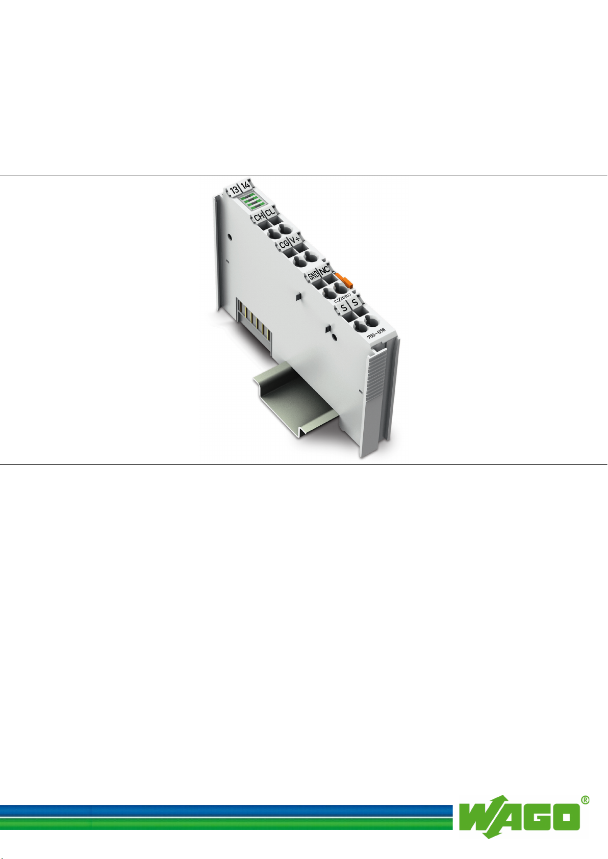
WAGO-I/O-SYSTEM 750
Manual
750-658
CAN Gateway
Version 1.2.0, valid from
Version 01/01
Pos: 3 /Alle S erie n (Al lge mei ne M odul e) /Rec htli ch es, Allg emei n es/I mpre ssu m f ür St and ard han dbüc h er - al lg. Ang aben, A nschr iften, Telef onnu mmern un d E-Mail -Adr esse n @ 3\mod_1219151118203_21.docx @ 21060 @ @ 1
FW/HW-
Page 2

2 WAGO-I/O-SYSTEM 750
750-658 CAN Gateway
© 2017 WAGO Kontakttechnik GmbH & Co. KG
All rights reserved.
WAGO Kontakttechnik GmbH & Co. KG
Hansastraße 27
D-32423 Minden
Phone: +49 (0) 571/8 87 – 0
Fax: +49 (0) 571/8 87 – 1 69
E-Mail: info@wago.com
Web: http://www.wago.com
Technical Support
Phone: +49 (0) 571/8 87 – 5 55
Fax: +49 (0) 571/8 87 – 85 55
E-Mail: support@wago.com
Every conceivable measure has been taken to ensure the accuracy and
completeness of this documentation. However, as errors can never be fully
excluded, we always appreciate any information or suggestions for improving the
documentation.
E-Mail: documentation@wago.com
We wish to point out that the software and hardware terms as well as the
trademarks of companies used and/or mentioned in the present manual are
generally protected by trademark or patent.
=== Ende der Li st e für Te xtm arke Ei nba nd_ vorn e ===
Manual
Version 1.2.0, valid from FW/HW-Version 01/01
Page 3

WAGO-I/O-SYSTEM 750 Table of Contents 3
750-658 CAN Gateway
Pos: 5 /Dok ument ati on allg em ein/ Verz eic hni sse /Inh alts ver zei chni s - Ü bersc hrift oG und Ver zeich nis @ 3\ mod_1219151230875_21.docx @ 21063 @ @ 1
Table of Contents
1 Notes about this Documentation ................................................................. 6
1.1 Validity of this Documentation ................................................................. 6
1.2 Copyright ................................................................................................... 6
1.3 Symbols ..................................................................................................... 7
1.4 Number Notation ....................................................................................... 9
1.5 Font Conventions ...................................................................................... 9
2 Important Notes ......................................................................................... 10
2.1 Legal Bases ............................................................................................. 10
2.1.1 Subject to Changes ............................................................................. 10
2.1.2 Personnel Qualifications ..................................................................... 10
2.1.3 Use of the WAGO-I/O-SYSTEM 750 in Compliance with Underlying
Provisions ........................................................................................... 10
2.1.4 Technical Condition of Specified Devices ......................................... 11
2.2 Safety Advice (Precautions) .................................................................... 12
3 CAN Technology ........................................................................................ 14
4 Device Description ..................................................................................... 15
4.1 View ........................................................................................................ 17
4.2 Connectors ............................................................................................... 18
4.2.1 Data Contacts/Internal Bus ................................................................. 18
4.2.2 Power Jumper Contacts/Field Supply ................................................ 19
4.2.3 CAGE CLAMP® Connectors ............................................................. 21
4.3 Display Elements .................................................................................... 22
4.4 Schematic Diagram ................................................................................. 23
4.5 Technical Data ........................................................................................ 24
4.5.1 Device Data ........................................................................................ 24
4.5.2 Supply ................................................................................................. 24
4.5.3 CAN Communication ......................................................................... 25
4.5.4 Connection Type ................................................................................ 25
4.5.5 Climatic Environmental Conditions ................................................... 25
4.6 Approvals ................................................................................................ 26
4.7 Standards and Guidelines ........................................................................ 27
5 Function Description ................................................................................. 28
5.1 Operating Modes ..................................................................................... 28
5.1.1 Sniffer Mode ....................................................................................... 29
5.1.2 Transparent Mode ............................................................................... 29
5.1.3 Mapped Mode ..................................................................................... 29
5.1.3.1 Map CAN Telegrams in Input Direction ....................................... 29
5.1.3.2 Map CAN Telegrams in Output Direction .................................... 30
5.1.3.2.1 "Content of the CAN telegram" Setting .................................... 30
5.1.3.2.2 "Send on request" Setting ......................................................... 31
5.1.3.2.3 "Send on change" Setting .......................................................... 31
5.1.3.2.4 "Cycle Time" Setting ................................................................ 31
5.1.3.3 Access CAN Telegrams via the Mailbox ...................................... 32
5.2 Filter Settings .......................................................................................... 33
5.2.1 "Overwrite" Setting ............................................................................ 33
Manual
Version 1.2.0, valid from FW/HW-Version 01/01
Page 4

4 Table of Contents WAGO-I/O-SYSTEM 750
750-658 CAN Gateway
5.2.2 "Keep All" Setting .............................................................................. 33
6 Process Image ............................................................................................. 34
6.1 Process Image in "Sniffer" Operating Mode ........................................... 35
6.1.1 Mailbox............................................................................................... 35
6.1.2 CAN User Data Range ....................................................................... 35
6.2 Process Image in "Transparent" Operating Mode ................................... 37
6.2.1 Mailbox............................................................................................... 37
6.2.2 CAN User Data Range ....................................................................... 37
6.3 Process Image in the "Mapped" Operating Mode ................................... 38
6.3.1 Mailbox............................................................................................... 38
6.3.2 Toggle Byte ........................................................................................ 38
6.3.3 Mapped Cyclical Data (CAN User Data) ........................................... 38
7 Mounting ..................................................................................................... 39
7.1 Mounting Sequence ................................................................................. 39
7.2 Inserting and Removing Devices ............................................................ 40
7.2.1 Inserting the I/O Module .................................................................... 40
7.2.2 Removing the I/O Module .................................................................. 41
8 Connect Devices ......................................................................................... 42
8.1 Connecting a Conductor to the CAGE CLAMP® ................................... 42
8.2 Connect CAN Bus ................................................................................... 43
9 Configuration and Parameterization ....................................................... 44
9.1 Configuration and Parameterization with WAGO-I/O-CHECK ............ 45
9.1.1 Configuration Dialog .......................................................................... 46
9.1.1.1 Toolbar ........................................................................................... 46
9.1.1.2 Function Area ................................................................................ 50
9.1.1.3 Diagnosis Area ............................................................................... 50
9.1.2 Load Parameters into the Application ................................................ 51
9.1.3 "Configuration" Dialog ...................................................................... 53
9.1.3.1 Set Mailbox Diagnosis ................................................................... 53
9.1.3.2 Set Mailbox Length ....................................................................... 56
9.1.3.3 Setting the Process Image Size ...................................................... 57
9.1.4 Function Area in the "Sniffer Mode" ................................................. 58
9.1.5 Function Area in the "Transparent Mode" ......................................... 59
9.1.6 Function Area in the "Mapped Mode" ............................................... 61
9.1.6.1 "PII" View ...................................................................................... 61
9.1.6.2 "PIO" View .................................................................................... 63
9.1.7 "CAN Parameter" Dialog ................................................................... 66
9.1.7.1 Select CAN Data Format ............................................................... 66
9.1.7.2 Set CAN Baud Rate ....................................................................... 67
9.1.8 "Filter" Dialog .................................................................................... 68
9.2 Configuration and Parameterization with e!COCKPIT .......................... 70
9.3 Startup with WAGO-I/O-PRO ................................................................ 71
10 Appendix ..................................................................................................... 72
10.1 Mailbox 2.0 Transmission Method ......................................................... 72
10.1.1 Message .............................................................................................. 72
10.1.2 Transmission Channel ........................................................................ 73
10.1.2.1 The Handshake Byte ...................................................................... 74
Manual
Version 1.2.0, valid from FW/HW-Version 01/01
Page 5

WAGO-I/O-SYSTEM 750 Table of Contents 5
750-658 CAN Gateway
10.1.3 Communication Phases ...................................................................... 75
10.1.3.1 Synchronization ............................................................................. 75
10.1.3.1.1 Mailbox Commands .................................................................. 75
10.1.3.1.2 Acknowledgement .................................................................... 76
10.1.3.1.3 Signaling ................................................................................... 76
10.1.3.1.4 Finite Automation ..................................................................... 77
10.1.3.2 Data Exchange ............................................................................... 78
10.1.3.2.1 Example .................................................................................... 79
10.2 Protocols Supported by Mailbox 2.0 ....................................................... 80
10.2.1 Protocol 0x80 (Parameter Access) ..................................................... 80
10.2.2 Protocol 0x81 (Diagnostics) ............................................................... 81
10.3 Overview of Parameters .......................................................................... 83
10.3.1 Table 0: Base Register ........................................................................ 83
10.3.2 Tables 50 … 55: Filter Configuration ................................................ 83
10.3.3 Tables 100 … 144: Configuration of Output Direction for "Mapped
Mode" ................................................................................................. 84
10.3.4 Tables 200 … 244: Configuration of Input Direction for "Mapped
Mode" ................................................................................................. 87
10.4 Register Communication ......................................................................... 89
10.4.1 Control/Status Byte ............................................................................ 90
10.4.2 Register Overview .............................................................................. 91
=== Ende der Li st e für Te xtm arke Ver zeic hni s_v or ne == =
11 Use in Hazardous Environments .............................................................. 92
11.1 Marking Configuration Examples ........................................................... 93
11.1.1 Marking for Europe According to ATEX and IEC-Ex ...................... 93
11.1.2 Marking for America According to NEC 500 .................................... 98
11.2 Installation Regulations ........................................................................... 99
11.2.1 Special Notes Regarding Explosion Protection .................................. 99
11.2.2 Special Notes Regarding ANSI/ISA Ex ........................................... 101
List of Figures .................................................................................................... 102
List of Tables ...................................................................................................... 104
Manual
Version 1.2.0, valid from FW/HW-Version 01/01
Page 6

6 Notes about this Documentation WAGO-I/O-SYSTEM 750
750-658 CAN Gateway
Pos: 7 /Alle Ser ie n (All ge mein e M odul e) /Üb ersc hri ften/ E ben e 1/Hi nw eis e zu dies er D o kume ntat ion - Üb erschr ift 1 @ 4\mod_1237987661750_21.docx @ 29029 @ 1 @ 1
1 Notes about this Documentation
Pos: 8 /Alle S erie n (Al lge mei ne M odul e) /Sic her hei ts- und sonstige Hinweise/Hinweis /Hi nwei s: D o kume ntat ion auf be wahr en @ 4\mod_1237987339812_21.docx @ 29026 @ @ 1
Always retain this documentation!
This documentation is part of the product. Therefore, retain the documentation
during the entire service life of the product. Pass on the documentation to any
subsequent user. In addition, ensure that any supplement to this documentation is
included, if necessary.
Pos: 9 /Alle S erie n (Al lge mei ne M odul e) /Üb ersc hri ften/ E ben e 2/G ülti g keits berei ch - Üb ersc hrift 2 @ 12\ mod_1338912448776_21.docx @ 96469 @ 2 @ 1
1.1 Validity of this Documentation
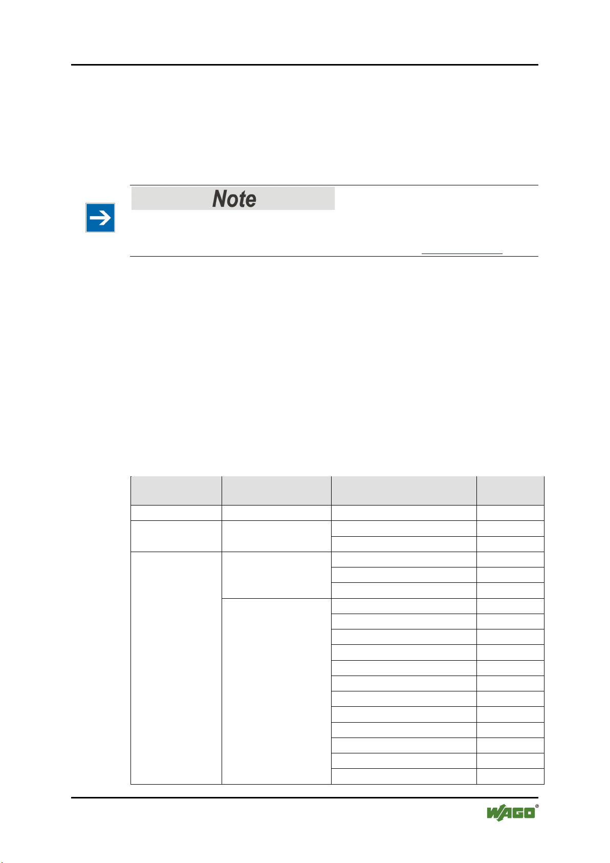
Pos: 10 /Ser ie 75 0 (WA GO-I/ O-SYS TEM )/H in weis e z ur D okum ent ati on/ Gül tigk eits ber eic h/G ültig k eits ber eich Dok um enta tio n Bus kl emme 75 0-x xxx, o hne V aria nten ang abe @ 14\mod_1358944037947_21.docx @ 109346 @ @ 1
This documentation is only applicable to the I/O module 750-658
(CAN Gateway).
Pos: 11 /All e S eri en ( Allg emei n e Mod ule) /R echtl ic hes , Al lgem ei nes/ Gült ig keit sber eic h D oku ment ati on Er gä nzung " ab < FW/H W/ SW- Vers ion> " @ 20\ mod_1407749774742_21.docx @ 161508 @ @ 1
This documentation is only applicable from FW/HW-Version 01/01.
Pos: 12 /Ser ie 75 0 (WA GO-I/ O-SYS TEM )/H in weis e z ur D okum ent ati on/Hi n weis e/Ac ht ung : Hin wei s z ur D oku ment ati on B us kle mme n 75 0-xxxx @ 4\mod_1237986979656_21.docx @ 29023 @ @ 1
The I/O module 750-658 shall only be installed and operated according to the
instructions in this manual and in the manual for the used fieldbus
coupler/controller.
Consider power layout of the WAGO-I/O-SYSTEM 750!
In addition to these operating instructions, you will also need the manual for the
used fieldbus coupler/controller, which can be downloaded at www.wago.com.
There, you can obtain important information including information on electrical
isolation, system power and supply specifications.
Pos: 13.1 /Al l e Ser ien ( Al lge mei ne M od ule)/Ü ber sc hrift e n/Eb ene 2/Ur h ebers chut z - Ü bers chrift 2 @ 23\mod_1435647042188_21.docx @ 184808 @ 2 @ 1
1.2 Copyright
Pos: 13.2 /Al l e Ser ien ( Al lge mei ne M od ule)/R ec htli ches , Al lg emei nes /Ur heb ersc hu tz ausf ührl ich @ 4\ mod_1235565145234_21.docx @ 27691 @ @ 1
This Manual, including all figures and illustrations, is copyright-protected. Any
further use of this Manual by third parties that violate pertinent copyright
provisions is prohibited. Reproduction, translation, electronic and phototechnical
filing/archiving (e.g., photocopying) as well as any amendments require the
written consent of WAGO Kontakttechnik GmbH & Co. KG, Minden, Germany.
Non-observance will involve the right to assert damage claims.
Pos: 13.3 /Dokumentation allgemein/Glieder ungselemente/---Seitenwechsel--- @ 3\mod_1221108045078_0.docx @ 21810 @ @ 1
Manual
Version 1.2.0, valid from FW/HW-Version 01/01
Page 7
WAGO-I/O-SYSTEM 750 Notes about this Documentation 7
750-658 CAN Gateway
Pos: 13.4 /Al l e Ser ien ( Al lge mei ne M od ule)/Ü ber sc hrift e n/Eb ene 2/S ym bole - Üb erschr if t 2 @ 1 3\mod_1351068042408_21.docx @ 105270 @ 2 @ 1
1.3 Symbols
Pos: 13.5.1 /All e Serie n (All gemei ne Mod ule)/ Sicher heits- und sonstige Hinweise/Gefahr/Gefahr: _Warnung vor Personen schä den allg emei n_ - Erläu terung @ 13\ mod_1343309450020_21.docx @ 101029 @ @ 1
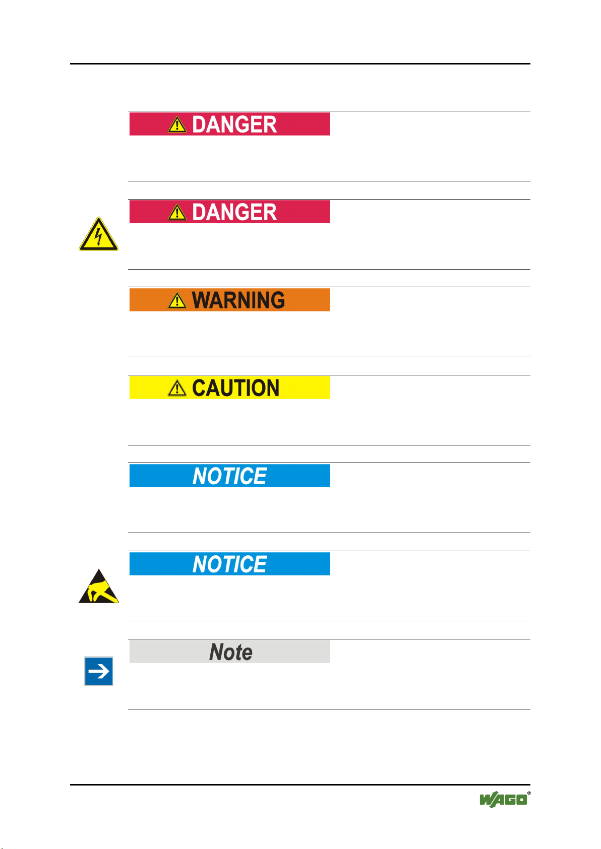
Personal Injury!
Indicates a high-risk, imminently hazardous situation which, if not avoided, will
result in death or serious injury.
Pos: 13.5.2 /Alle Ser ien ( Al lg emei ne M od ule)/ Sic herh eits - u nd sons tige Hi nweis e/Gef ahr/G efahr : _War nung vor Person ensch äden d urch el ektris chen Str om_ - Erläuterung @ 13\mod_1343309694914_21.docx @ 101030 @ @ 1
Personal Injury Caused by Electric Current!
Indicates a high-risk, imminently hazardous situation which, if not avoided, will
result in death or serious injury.
Pos: 13.5.3 /All e Serie n (All gemei ne Mod ule)/ Sicher heits- und sons ti ge Hi n weis e/W arn ung/ War nung : _ Warn ung vor P erso nensc h äde n al lgem ei n_ - Er läut eru ng @ 13\mod_1343309877041_21.docx @ 101035 @ @ 1
Personal Injury!
Indicates a moderate-risk, potentially hazardous situation which, if not avoided,
could result in death or serious injury.
Pos: 13.5.4 /All e Serie n (All gemei ne Mod ule)/ Sicher heits- und so nstig e Hin weise/ Vorsic ht/V orsich t: _War nung vor Pers onensc häd en allge mein_ - Erläuterung @ 13\mod_1343310028762_21.docx @ 101038 @ @ 1
Personal Injury!
Indicates a low-risk, potentially hazardous situation which, if not avoided, may
result in minor or moderate injury.
Pos: 13.5.5 /All e Serie n (All gemei ne Mod ule)/ Sicher heits- und sons ti ge Hi n weis e/Ac htu ng/ Ach tung : _ War nung vor Sac hsc häd en al lg emei n_ - Erläuterung @ 13\mod_1343310134623_21.docx @ 101041 @ @ 1
Damage to Property!
Indicates a potentially hazardous situation which, if not avoided, may result in
damage to property.
Pos: 13.5.6 /All e Serie n (All gemei ne Mod ule)/ Sicher heits- und sonsti ge Hin weise/ Achtu ng/Ac htung : _War nung vor Sachsc häden durc h elektr ostatis che Au fladu ng_ - Erl äut erung @ 13\mod_1343310227702_21.docx @ 101044 @ @ 1
Damage to Property Caused by Electrostatic Discharge (ESD)!
Indicates a potentially hazardous situation which, if not avoided, may result in
damage to property.
Pos: 13.5.7 /All e Serie n (All gemei ne Mo dul e)/ Sich erh eits- und sonstige Hinweise/Hinweis/Hinweis: _Wichtiger Hinweis allgemein_ - Erläuterung @ 13\mod_1343310326906_21.docx @ 101047 @ @ 1
Important Note!
Indicates a potential malfunction which, if not avoided, however, will not result in
damage to property.
Pos: 13.5.8 /All e Serie n (All gemei ne Mod ule)/ Sicher heits- und sons ti ge Hi n weis e/Inf or mati on/I nf orma tio n: _ Wei ter e Inf or mati on allg emei n_ - Erl äuter ung @ 13 \mod_1343310439814_21.docx @ 101051 @ @ 1
Manual
Version 1.2.0, valid from FW/HW-Version 01/01
Page 8

8 Notes about this Documentation WAGO-I/O-SYSTEM 750
750-658 CAN Gateway
Additional Information:
Refers to additional information which is not an integral part of this
documentation (e.g., the Internet).
Pos: 13.6 /Dokumentation allgemein/Glieder ungselemente/---Seitenwechsel--- @ 3\mod_1221108045078_0.docx @ 21810 @ @ 1
Manual
Version 1.2.0, valid from FW/HW-Version 01/01
Page 9

WAGO-I/O-SYSTEM 750 Notes about this Documentation 9
Table 1: Number Notation
Number Code
Example
Note
Decimal
100
Normal notation
Hexadecimal
0x64
C notation
Binary
'100'
'0110.0100'
In quotation marks, nibble separated with
dots (.)
Table 2: Font Conventions
Font Type
Indicates
italic
Names of paths and data files are marked in italic-type.
e.g.: C:\Program Files\WAGO Software
Menu
Menu items are marked in bold letters.
e.g.: Save
>
A greater-than sign between two names means the selection of a
e.g.: File > New
Input
Designation of input or optional fields are marked in bold letters,
e.g.: Start of measurement range
“Value”
Input or selective values are marked in inverted commas.
e.g.: Enter the value “4 mA” under Start of measurement range.
[Button]
Pushbuttons in dialog boxes are marked with bold letters in square
e.g.: [Input]
[Key]
Keys are marked with bold letters in square brackets.
e.g.: [F5]
750-658 CAN Gateway
Pos: 13.7 /Al l e Ser ien ( Al lge mei ne M od ule)/Ü ber sc hrift e n/Eb ene 2/D arst ell ung der Z a hle nsys tem e - Ü bers chri ft 2 @ 23\mod_1435647128078_21.docx @ 184811 @ 2 @ 1
1.4 Number Notation
Pos: 13.8 /Al l e Ser ien ( Al lge mei ne M od ule)/R ec htli ches , Al lg emei nes /Za hle nsy st eme @ 3\mod_1221059454015_21.docx @ 21711 @ @ 1
Pos: 13.9 /Al l e Ser ien ( Al lge mei ne M od ule)/Ü ber sc hrift e n/Eb ene 2/Sc hr ift kon venti one n - Ü bersc hr ift 2 @ 23\ mod_1435647186005_21.docx @ 184814 @ 2 @ 1
1.5 Font Conventions
Pos: 13.10 / All e S erie n (Al lge mei ne M o dule) /Re cht lich es, All ge mein es/ Schr ift kon venti on en @ 3\mod_1221059521437_21.docx @ 21714 @ @ 1
menu item from a menu.
brackets.
Pos: 14 /Do kum ent atio n all ge mei n/Gl ieder ung s elem ente /---Seit en wechs el--- @ 3\mod_1221108045078_0.docx @ 21810 @ @ 1
Manual
Version 1.2.0, valid from FW/HW-Version 01/01
Page 10

10 Important Notes WAGO-I/O-SYSTEM 750
750-658 CAN Gateway
Pos: 15 /All e S eri en ( Allg emei n e Mod ule) /Ü ber schri fte n/ Ebe ne 1/ Wic htig e Er läu ter unge n - Über schri ft 1 @ 4\mod_1241428899156_21.docx @ 32170 @ 1 @ 1
2 Important Notes
Pos: 16.1 /Al l e Ser ien ( Al lge mei ne M od ule)/R ec htli ches , Al lg emei nes /Wi chti g e Erl äuter ung en - Ei nleit u ng @ 3\mod_1221059818031_21.docx @ 21717 @ @ 1
This section includes an overall summary of the most important safety
requirements and notes that are mentioned in each individual section. To protect
your health and prevent damage to devices as well, it is imperative to read and
carefully follow the safety guidelines.
Pos: 16.2 /Al l e Ser ien ( Al lge mei ne M od ule)/Ü ber sc hrift e n/Eb ene 2/R echt lic he G run dlag en - Üb erschr ift 2 @ 3\mod_1221060626343_21.docx @ 21726 @ 2 @ 1
2.1 Legal Bases
Pos: 16.3 /Al l e Ser ien ( Al lge mei ne M od ule)/R ec htli ches , Al lg emei nes /Ä nder ung sv orbeh alt - Üb ersc hrift 3 un d Inhalt @ 3\mod_1221060036484_21.docx @ 21720 @ 3 @ 1
2.1.1 Subject to Changes
WAGO Kontakttechnik GmbH & Co. KG reserves the right to provide for any
alterations or modifications that serve to increase the efficiency of technical
progress. WAGO Kontakttechnik GmbH & Co. KG owns all rights arising from
the granting of patents or from the legal protection of utility patents. Third-party
products are always mentioned without any reference to patent rights. Thus, the
existence of such rights cannot be excluded.
Pos: 16.4 /Serie 750 (WAGO-I/O-S YSTEM )/Wi chtig e Erlä uteru ngen/ Person alqu alifi kation/ Pers onalq ualifi katio n 750- xxxx - Über sc hrift 3 un d In halt @ 3\ mod_1224061208046_21.docx @ 24063 @ 3 @ 1
2.1.2 Personnel Qualifications
All sequences implemented on WAGO-I/O-SYSTEM 750 devices may only be
carried out by electrical specialists with sufficient knowledge in automation. The
specialists must be familiar with the current norms and guidelines for the devices
and automated environments.
All changes to the coupler or controller should always be carried out by qualified
personnel with sufficient skills in PLC programming.
Pos: 16.5 /Serie 750 (WAGO-I/O-S YSTEM )/Wi chtig e Erlä uteru ngen/ Bestim mung sgemäß e Ver wendung /B estim mungsg emäß e Verwe ndung 750-xxxx - Ü bersc hrift 3 u nd Inh alt @ 3\mod_1224064151234_21.docx @ 24070 @ 3 @ 1
2.1.3 Use of the WAGO-I/O-SYSTEM 750 in Compliance with Underlying Provisions
Fieldbus couplers, fieldbus controllers and I/O modules found in the modular
WAGO-I/O-SYSTEM 750 receive digital and analog signals from sensors and
transmit them to actuators or higher-level control systems. Using programmable
controllers, the signals can also be (pre-) processed.
The devices have been developed for use in an environment that meets the IP20
protection class criteria. Protection against finger injury and solid impurities up to
12.5 mm diameter is assured; protection against water damage is not ensured.
Unless otherwise specified, operation of the devices in wet and dusty
environments is prohibited.
Operating the WAGO-I/O-SYSTEM 750 devices in home applications without
further measures is only permitted if they meet the emission limits (emissions of
interference) according to EN 61000-6-3. You will find the relevant information
in the section “Device Description” > “Standards and Guidelines” in the manual
for the used fieldbus coupler/controller.
Manual
Version 1.2.0, valid from FW/HW-Version 01/01
Page 11

WAGO-I/O-SYSTEM 750 Important Notes 11
750-658 CAN Gateway
Appropriate housing (per 2014/34/EU) is required when operating the WAGOI/O-SYSTEM 750 in hazardous environments. Please note that a prototype test
certificate must be obtained that confirms the correct installation of the system in
a housing or switch cabinet.
Pos: 16.6 /Al l e Ser ien ( Al lge mei ne M od ule)/R ec htli ches , Al lg emei nes /Te ch nisc her Z us tand der Ger ät e - Ü bersc hr ift 3 u nd I nhal t @ 3\mod_1221060446109_21.docx @ 21723 @ 3 @ 1
2.1.4 Technical Condition of Specified Devices
The devices to be supplied ex works are equipped with hardware and software
configurations, which meet the individual application requirements. WAGO
Kontakttechnik GmbH & Co. KG will be exempted from any liability in case of
changes in hardware or software as well as to non-compliant usage of devices.
Please send your request for modified and new hardware or software
configurations directly to WAGO Kontakttechnik GmbH & Co. KG.
Pos: 16.7 /Dokumentation allgemein/Glieder ungselemente/---Seitenwechsel--- @ 3\mod_1221108045078_0.docx @ 21810 @ @ 1
Manual
Version 1.2.0, valid from FW/HW-Version 01/01
Page 12
12 Important Notes WAGO-I/O-SYSTEM 750
750-658 CAN Gateway
Pos: 16.8 /Al l e Ser ien ( Al lge mei ne M od ule)/Ü ber sc hrift e n/Eb ene 2/Si cher hei ts hin weis e - Ü bersc hrift 2 @ 6\mod_1260180299987_21.docx @ 46724 @ 2 @ 1
2.2 Safety Advice (Precautions)
Pos: 16.9 /Al l e Ser ien ( Al lge mei ne M od ule)/ Sic herh eits - u nd s ons tig e Hi nweis e/ Einl eit ung Sic herh eits hin wei se H ar dwar e @ 6\mod_1260180170493_21.docx @ 46720 @ @ 1
For installing and operating purposes of the relevant device to your system the
following safety precautions shall be observed:
Pos: 16.10. 1 /A lle Ser ien ( All ge mein e M odul e)/ Sic her heits - un d s onsti ge Hin wei se/G ef ahr/ Gef ahr: Nic ht an G erät en unt er S pann ung ar bei ten! @ 6\mod_1260180365327_21.docx @ 46727 @ @ 1
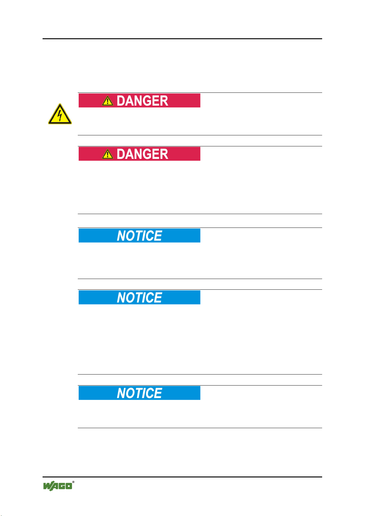
Do not work on devices while energized!
All power sources to the device shall be switched off prior to performing any
installation, repair or maintenance work.
Pos: 16.10. 2 /S eri e 75 0 ( WAG O-I/O- SYST EM) /Wic htig e Er l äuter ung en /Sic her hei ts- und s onst ige H i nwei se/ Gef ahr/ Gefa hr: Ei nbau 07 50- xxxx nur in Geh äusen, Schrä nken oder ele ktrisc hen Betr iebsräumen! @ 6\mod_1260180556692_21.docx @ 46731 @ @ 1
Install the device only in appropriate housings, cabinets or in electrical
operation rooms!
The WAGO-I/O-SYSTEM 750 and its components are an open system. As such,
install the system and its components exclusively in appropriate housings,
cabinets or in electrical operation rooms. Allow access to such equipment and
fixtures to authorized, qualified staff only by means of specific keys or tools.
Pos: 16.10. 3 /A lle Ser ien ( All ge mein e M odul e)/ Sic her heits - un d so nstig e H in weis e/G efa hr/G ef ahr: Unf all verh ütung s vorsc hr ift en b each te n! @ 6\mod_1260180657000_21.docx @ 46735 @ @ 1
Pos: 16.10. 4 /A lle Ser ien ( All ge mein e M odul e)/ Sic her heits - un d s onsti ge Hin wei se/G ef ahr/ Gef ahr: Auf nor mg erec hte n A nschl us s ac ht en! @ 6\ mod_1260180753479_21.doc x @ 46739 @ @ 1
Pos: 16.11. 1 /A lle Ser ien ( All ge mein e M odul e)/ Sic her heits - un d s onsti ge Hin wei se/A cht ung /Ac htu ng: D ef ekt e od er besch ädig te Ger ät e aus taus ch en! @ 6 \mod_1260180857358_21.docx @ 46743 @ @ 1
Replace defective or damaged devices!
Replace defective or damaged device/module (e.g., in the event of deformed
contacts), since the long-term functionality of device/module involved can no
longer be ensured.
Pos: 16.11. 2 /A lle Ser ien ( All ge mein e M odul e)/ Sic her heits - un d so nsti ge Hin weis e/A cht ung /Ac htu ng: G erä te vor kriec he nde n u nd is oli ere nden Sto ff en sc hüt zen! @ 6\mod_1260181036216_21.docx @ 46747 @ @ 1
Protect the components against materials having seeping and insulating
properties!
The components are not resistant to materials having seeping and insulating
properties such as: aerosols, silicones and triglycerides (found in some hand
creams). If you cannot exclude that such materials will appear in the component
environment, then install the components in an enclosure being resistant to the
above-mentioned materials. Clean tools and materials are imperative for handling
devices/modules.
Pos: 16.11. 3 /A lle Ser ien ( All ge mein e M odul e)/ Sic her heits - und sonstige Hinweise/Achtung/Achtung: Reinigung nur mit zulässigen Mat eri alie n! @ 6\mod_1260181203293_21.docx @ 46751 @ @ 1
Clean only with permitted materials!
Clean soiled contacts using oil-free compressed air or with ethyl alcohol and
leather cloths.
Pos: 16.11. 4 /A lle Ser ien ( All ge mein e M odul e)/ Sic her heits - und sonstige Hinweise/Achtung/Achtung: Kein Kontaktspray verwenden! @ 6\mod_1260181290808_21.docx @ 46755 @ @ 1
Manual
Version 1.2.0, valid from FW/HW-Version 01/01
Page 13

WAGO-I/O-SYSTEM 750 Important Notes 13
750-658 CAN Gateway
Do not use any contact spray!
Do not use any contact spray. The spray may impair contact area functionality in
connection with contamination.
Pos: 16.11. 5 /A lle Ser ien ( All ge mein e M odul e)/ Sic her heits - un d s onsti ge Hin wei se/A cht ung /Ac htu ng: V er pol ung en d er D aten- und V ersorg ungs leit ungen vermeid en! @ 6\ mod_1260184045744_21.docx @ 46767 @ @ 1
Do not reverse the polarity of connection lines!
Avoid reverse polarity of data and power supply lines, as this may damage the
devices involved.
Pos: 16.11. 6 /A lle Ser ien ( All ge mein e M odul e)/ Sic her heits - un d s onsti ge Hin wei se/A cht ung /Ac htu ng: El e ktros tati sc he Entl adu ng verm ei den! @ 6\ mod _1260181364729_21.docx @ 46759 @ @ 1
Avoid electrostatic discharge!
The devices are equipped with electronic components that may be destroyed by
electrostatic discharge when touched. Please observe the safety precautions
against electrostatic discharge per DIN EN 61340-5-1/-3. When handling the
devices, please ensure that environmental factors (personnel, work space and
packaging) are properly grounded.
Pos: 17 /Dokum entati on allg emei n/Gli ederung sele mente /---Seit enwe chs el--- @ 3\mod_1221108045078_0.docx @ 21810 @ @ 1
Manual
Version 1.2.0, valid from FW/HW-Version 01/01
Page 14

14 CAN Technology WAGO-I/O-SYSTEM 750
750-658 CAN Gateway
Pos: 18 /Ser ie 75 0 (WA GO-I/ O-SYS TEM )/F eld bus komm uni katio n/C AN/C AN-Kommunikation 750-0658 @ 13\mod_1355479155100_21.docx @ 107624 @ 1 @ 1
3 CAN Technology
The CAN bus is a an asynchronous serial bus system for connecting intelligent
actuators and sensors to the control level. CAN standards for "Controller Area
network" and defines a communication standard developed in the mid-1980s for
data transmission in automobiles.
The so-called "Data Link Layer" is defined in the CAN specification. This is the
physical layer and data data link layer. The message format is described in detail.
In addition, the so-called "CAN Application Layer" (CAL) is defined in the CAN
specification. CAL is a general description language for CAN networks and
makes a number of communication services available.
Network management powers up the network in a simplified manner. This
network can be extended by the user as required.
CAN is a so-called "Multi-Master Bus System". Contrary to other fieldbus
systems, the I/O modules connected to the bus are not addressed, but the messages
are identified. The devices are allowed to send messages whenever the bus is
available. Bus conflicts are solved by assigning messages a specific priority. This
priority is defined by the so-called "CAN-ID" (CAN identifier). It is uniquely
assigned to a communication object. The smaller the identifier, the higher the
priority. Thus, communication without bus master module is thus also possible.
There are two CAN standards:
• "2.0A Standard Frame"
• "2.0B Extended Frame"
The "2.0A Standard Frame" makes it possible to address up to 211 different CAN
identifiers. The "2.0B Extended Frame" was later developed to support up to 229
different CAN identifiers.
Each bus node decides by itself when it wants to send data. However, it is also
possible to request other bus nodes to send data. This request happens via the socalled "Remote Frame".
Based on CAN, various protocols have been established on the market at higher
layers. These may include CANopen, DeviceNet and SAE J1939. Support for
these protocols is left to future module variants.
Additional information about the CAN bus!
Additional information about the CAN bus is available on the Internet at
www.can-cia.org.
Manual
Version 1.2.0, valid from FW/HW-Version 01/01
Page 15
WAGO-I/O-SYSTEM 750 Device Description 15
Table 3: 750-658 Compatibility List – Fieldbus Couplers/Controllers
Fieldbus
PROFIBUS
Fieldbus coupler
750-333
17
PROFINET
Fieldbus coupler
750-375
03
750-377
03
ETHERNET
Fieldbus coupler
750-341
08
750-342
17
750-352
02
Fieldbus controller
750-841
19
750-842
18
750-843
02
750-871
07
750-872
03
750-873
05
750-880
03
750-880/0025-0001
03
750-880/0025-0002
03
750-881
03
750-882
02
750-884
03
750-658 CAN Gateway
Pos: 19 /Dokum entati on allg emei n/ Glie derung s elem ente /---Seit en wechs el--- @ 3\mod_1221108045078_0.docx @ 21810 @ @ 1
Pos: 20 /All e S eri en ( Allg emei n e Mod ule) /Ü ber schri fte n/ Ebe ne 1/ Ger äte bes chr eib ung - Ü ber schr if t 1 @ 3\ mod_1233756084656_21.doc x @ 27096 @ 1 @ 1
4 Device Description
Pos: 21.1 /Serie 750 (WAGO-I/O-SYSTEM)/Gerätebeschreibung/Einleitung/Anwendung/SO/Anwendung 750- 0658 @ 14\mod_1358947377666_21.docx @ 109393 @ @ 1
The I/O module 750-658 is used to connect a CAN bus network to a PLC
independent of the fieldbus.
The I/O module supports the physical layer and data link layer by default.
Pos: 21.2 /Serie 750 (WAGO-I/O-S YSTEM )/Wi chtig e Erlä uteru ngen/ Sicher heits- und so nstig e H inw eis e/Hi nwei s/Hi n weis : H öher e Pr ot okol lschi cht e n unt erst ütz en @ 14\ mod_1360327953696_21.docx @ 111249 @ @ 1
Support higher protocol layers!
Use IEC-61131-compliant function blocks to support the I/O module of higher
protocol layers. The function blocks can be downloaded at www.wago.com.
Pos: 21.3 /Serie 750 (WAGO-I/O-S YST EM)/ Ger äteb esc hrei bung /Ei nlei tung /I/ O-Besc hrei bu ng/ SO/I/ O-Beschreibung 750-0658 @ 14\mod_1358948130403_21.docx @ 109442 @ @ 1
The I/O module can be configured and parameterized via:
• WAGO-I/O-CHECK
• e!COCKPIT,
• PROFIBUS GSD or
• Function blocks
Pos: 22 /Ser ie 75 0 (WA GO-I/ O-SYS TEM )/ Ger äteb esc hrei bu ng/Ei nlei tu ng/E ins atz ber eich /Ei ns atzber ei ch 7 50- xxx x nur Koppl er/C ontrol ler a us Kompa tibili tätsli ste @ 4\ mod_1242389440265_21.docx @ 33262 @ @ 1
The 750-658 module can be used with the fieldbus couplers and controllers of the
WAGO-I/O-SYSTEM 750 of the specified version or higher listed in the
“Compatibility list” table.
Pos: 23 /Ser ie 75 0 (WA GO-I/ O-SYS TEM )/ Gerät ebes chr eibu ng/Ei nlei tung /Eins atz bereich /Ko mpatibi lit ätslist en/K ompati bilit ätsli ste 750- 0658 @ 14\mod_1361526228651_21.docx @ 112733 @ @ 1
Bus System
Couplers/Controllers
Item Number Firmware
Manual
Version 1.2.0, valid from FW/HW-Version 01/01
Page 16

16 Device Description WAGO-I/O-SYSTEM 750
Table 3: 750-658 Compatibility List – Fieldbus Couplers/Controllers
Fieldbus
Couplers/Controllers
750-885
04
DeviceNet
Fieldbus coupler
750-306
4K
ECO fieldbus coupler
750-346
10
Fieldbus controller
750-806
10
CANopen
Fieldbus coupler
750-337
19
750-338
19
ECO fieldbus coupler
750-347
08
750-348
08
Fieldbus controller
750-837
16
750-838
16
EtherCAT
Fieldbus coupler
750-354
01
KNX
Fieldbus controller
750-849
05
750-889
07
BACnet
Fieldbus controller
750-830
03
LONWORKS
Fieldbus coupler
750-319
05
Fieldbus controller
750-819
09
Various
PFC200
750-820x
02
Table 4: 750-658 Compatibility List – IPC
Bus System
IPC
Item Number
Description
WAGO-IPC
IPC
758-0870/0000-0010
Firmware revision 2.4.31 / 0111
758-0870/0000-0111
Firmware revision 01.01.26(05)
758-0875/0000-0111
Firmware revision 01.01.26(05)
758-0876/0000-0112
Firmware revision 01.01.26(05)
750-658 CAN Gateway
Bus System
Item Number Firmware
Pos: 24 /Dokum entati on allg emei n/Gli ederung sele mente /---Seit enwe chs el--- @ 3\mod_1221108045078_0.docx @ 21810 @ @ 1
Internal data bus FW revision 01.02.10(12)
Internal data bus FW revision 01.02.10(12)
Internal data bus FW revision 01.02.10(12)
Internal data bus FW revision 01.02.10(12)
Manual
Version 1.2.0, valid from FW/HW-Version 01/01
Page 17
WAGO-I/O-SYSTEM 750 Device Description 17
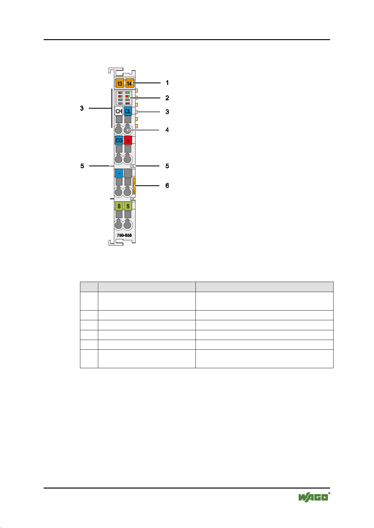
Table 5: Legend for Figure “View”
Pos.
Description
Details See Section
1
Marking possibility with MiniWSB
--2
Status LEDs
“Device Description” > “Display Elements”
3
Data contacts
“Device Description” > “Connectors”
4
CAGE CLAMP® connectors
“Device Description” > “Connectors”
5
Power jumper contacts
“Device Description” > “Connectors”
6
Release tab
“Mounting” > “Inserting and Removing
Devices”
750-658 CAN Gateway
Pos: 25 /All e S eri en ( Allg emei n e Mod ule) /Ü ber schri fte n/ Ebe ne 2/ Ans ic ht - Ü bers chri ft 2 @ 4\mod_1240984217343_21.docx @ 31958 @ 2 @ 1
4.1 View
Pos: 26 /Ser ie 75 0 (WA GO-I/ O-SYS TEM) /Ger ätebes chrei bung /Ansic ht/S onder klem men/A nsicht 750-06 58 - A bb. @ 14\ mod_1358344956644_21.docx @ 108848 @ @ 1
Figure 1: View
Pos: 27 /Ser ie 75 0 (WA GO-I/ O-SYS TEM )/ Ger äteb esc hrei bu ng/A nsic ht /Ans ic ht C ageCl a mp®_ Leg ende mi t LED s, mit 1 E ntri eg elung sl asch e @ 15\ mod_1370867188922_21.docx @ 122225 @ @ 1
Pos: 28 /D okum ent atio n al lge mein/ Gli eder ungs ele me nte/---Sei te nwec hsel--- @ 3\ mod_1221108045078_0.docx @ 21810 @ @ 1
Manual
Version 1.2.0, valid from FW/HW-Version 01/01
Page 18
18 Device Description WAGO-I/O-SYSTEM 750
750-658 CAN Gateway
Pos: 29 /All e S eri en ( Allg emei n e Mod ule) /Ü ber schri fte n/ Ebe ne 2/ Ans chl üss e - Üb ersc hrift 2 @ 4\ mod_1240984262656_21.docx @ 31961 @ 2 @ 1
4.2 Connectors
Pos: 30 /Serie 750 (WAGO-I/O-SYST EM) /Ger ät ebesc hrei bung /A nschl üss e/Da ten kont akt e/Kl em menbu s - Ü bersc hrift 3 @ 6\ mod_1256294684083_21.docx @ 43660 @ 3 @ 1
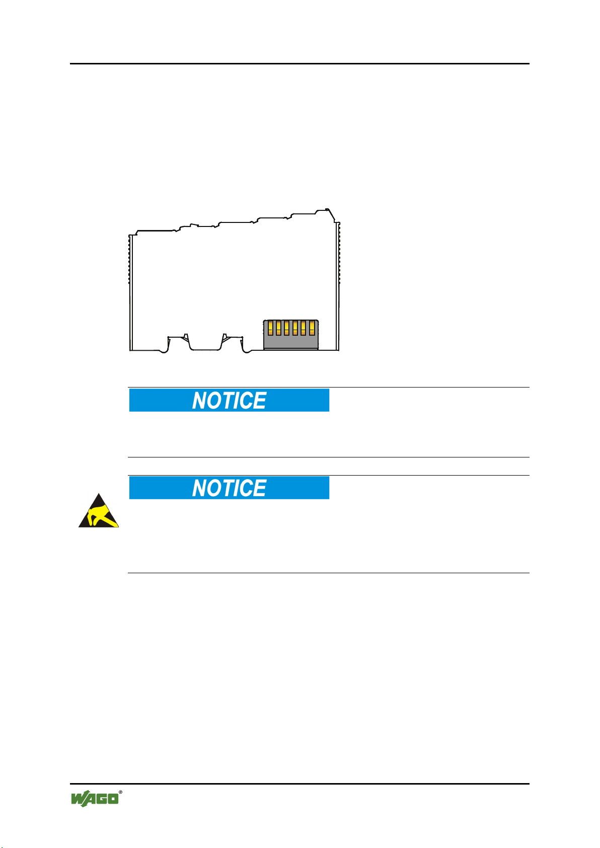
4.2.1 Data Contacts/Internal Bus
Pos: 31.1 /Serie 750 (WAGO-I/O-S YST EM)/ Ger äteb esc hrei bung /Ans chl üsse /Da ten konta kt e - Fel dbu skop pler/ -con trol l er, A bbil dung u nd B esc hrei bung @ 3\mod_1231771259187_21.docx @ 26002 @ @ 1
Communication between the fieldbus coupler/controller and the I/O modules as
well as the system supply of the I/O modules is carried out via the internal bus. It
is comprised of 6 data contacts, which are available as self-cleaning gold spring
contacts.
Figure 2: Data Contacts
Pos: 31.2 /Serie 750 (WAGO-I/O-S YSTEM )/Wi chtig e Erlä uteru ngen/ Sicher heits- und so nstig e H inw eis e/Ac htu ng/A ch tung : Bus kl em men nic ht a uf G oldf eder kon ta kte l eg en! @ 7 \mod_1266318463636_21.docx @ 50695 @ @ 1
Do not place the I/O modules on the gold spring contacts!
Do not place the I/O modules on the gold spring contacts in order to avoid soiling
or scratching!
Pos: 31.3 /Serie 750 (WAGO-I/O-S YSTEM )/Wi chtig e Erlä uteru ngen/ Sicher heits- und sonstige Hinweise/Achtung/Achtung: ESD - Auf gute Erdung der U mg ebu ng ac ht en! @ 7\ mod_1266318538667_21.docx @ 50708 @ @ 1
Ensure that the environment is well grounded!
The devices are equipped with electronic components that may be destroyed by
electrostatic discharge. When handling the devices, ensure that the environment
(persons, workplace and packing) is well grounded. Avoid touching conductive
components, e.g. data contacts.
Pos: 32 /Dokum entati on allg emei n/Gli ederung sele mente /---Seit enwe chs el--- @ 3\mod_1221108045078_0.docx @ 21810 @ @ 1
Manual
Version 1.2.0, valid from FW/HW-Version 01/01
Page 19
WAGO-I/O-SYSTEM 750 Device Description 19
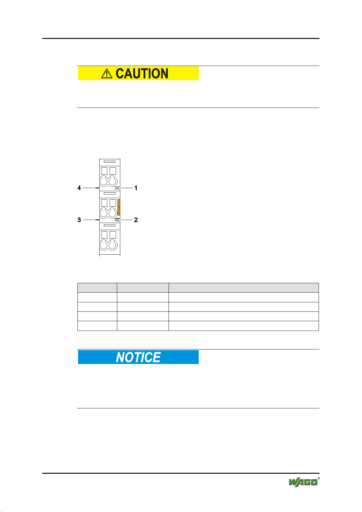
Table 6: Legend for Figure “Power Jumper Contacts”
Contact
Type
Function
1
Spring contact
Potential transmission (Uv) for field supply
2
Spring contact
Potential transmission (0 V) for field supply
3
Blade contact
Potential feed-in (0 V) for field supply
4
Blade contact
Potential feed-in (Uv) for field supply
750-658 CAN Gateway
Pos: 33 /Serie 750 (WAGO-I/O-SYST EM) /Ger ät ebesc hrei bung /A nschl üss e/L eist ungs kont akt e/Fel d versor gu ng - Üb ersc hrift 3 @ 6\ mod_1256294692864_21.docx @ 43664 @ 3 @ 1
4.2.2 Power Jumper Contacts/Field Supply
Pos: 34.1 /Serie 750 (WAGO-I/O-S YSTEM )/Wi chtig e Erlä uteru ngen/ Sicher heits- und so nstig e H inw eis e/Vor sic ht/ Vor sic ht: Verl etz ungs ge fahr dur ch s ch arf kant ige M ess er kont akt e! @ 6\mod_1256193279401_21.docx @ 43414 @ @ 1
Risk of injury due to sharp-edged blade contacts!
The blade contacts are sharp-edged. Handle the I/O module carefully to prevent
injury.
Pos: 34.2 /Serie 750 (WAGO-I/O-S YSTEM )/Ger äteb eschr eibu ng/Ans chl üsse/L eistu ngs kontakt e 2 LK (Mess er/F eder) - Einlei tung @ 1 5\mod_1371721641099_21.docx @ 123714 @ @ 1
The I/O module 750-658 has 2 self-cleaning power jumper contacts that supply
and transmit power for the field side. The contacts on the left side of the I/O
module are designed as blade contacts and those on the right side as spring
contacts.
Pos: 34.3 /Serie 750 (WAGO-I/O-S YST EM)/ Geräte besc hrei bung/A nschl üsse /Leist ungs konta kte 2 LK (M esser/ Feder ) - Abbi ldu ng, ei nf ac he Br eit e - S tan dar d @ 1 5\mod_1367500700037_21.docx @ 118396 @ @ 1
Figure 3: Power Jumper Contacts
Pos: 34.4 /Serie 750 (WAGO-I/O-S YSTEM )/Ger äteb eschr eibu ng/Ans chl üsse/L eistu ngs kontakt e 2 LK (Mess er/F eder) - Legen de @ 15\ mod_1371721352500_21.docx @ 123710 @ @ 1
Pos: 34.5 /Serie 750 (WAGO-I/O-S YSTEM )/Wi chtig e Erlä uteru ngen/ Sicher heits- und sonstig e Hinw eise/ Achtu ng/Ac htung : Maxi maler S trom Lei stung skon takte 10 A @ 3\mod_1226499143500_21.docx @ 25029 @ @ 1
Do not exceed maximum current via power jumper contacts!
The maximum current to flow through the power jumper contacts is 10 A.
Greater currents can damage the contacts.
When configuring your system, ensure that this current is not exceeded.
If exceeded, insert an additional supply module.
Pos: 34.6 /Serie 750 (WAGO-I/O-S YSTEM )/Wi chtig e Erlä uteru ngen/ Sicher heits- und so nstig e H inw eis e/Hi nwei s/Hi n weis : Po tent ial ei nspei se kle mme für Erd e ei nse tze n! ( kei ne L K für Er de) @ 3 \mod_1226499037468_21.docx @ 25023 @ @ 1
Manual
Version 1.2.0, valid from FW/HW-Version 01/01
Page 20

20 Device Description WAGO-I/O-SYSTEM 750
750-658 CAN Gateway
Use supply modules for ground (earth)!
The I/O module has no power jumper contacts for receiving and transmitting the
earth potential. Use a supply module when an earth potential is needed for the
subsequent I/O modules.
Pos: 35 /D okum entati on allg emei n/Gli ederung sele mente /---Seit enwe chs el--- @ 3\mod_1221108045078_0.docx @ 21810 @ @ 1
Manual
Version 1.2.0, valid from FW/HW-Version 01/01
Page 21
WAGO-I/O-SYSTEM 750 Device Description 21
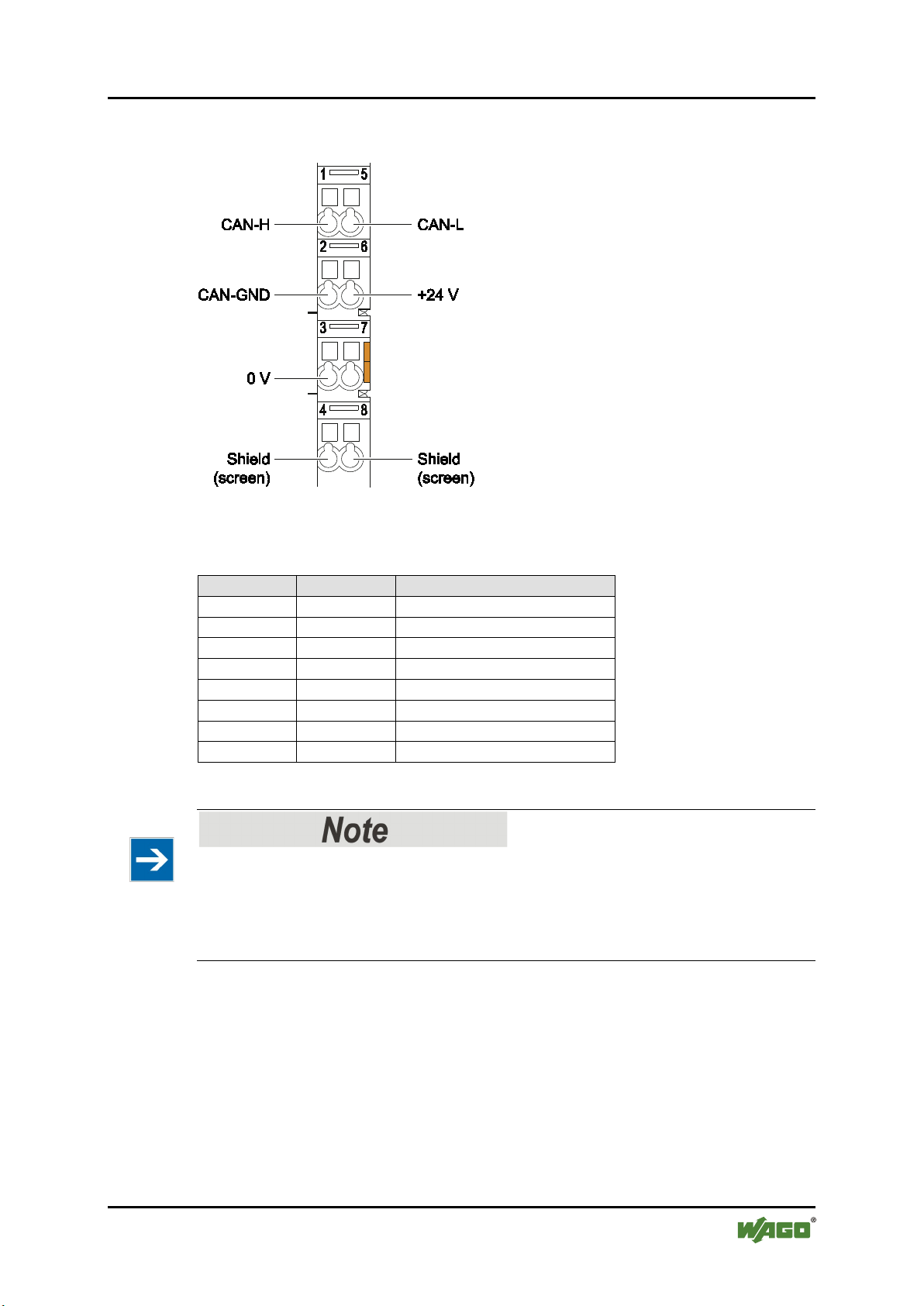
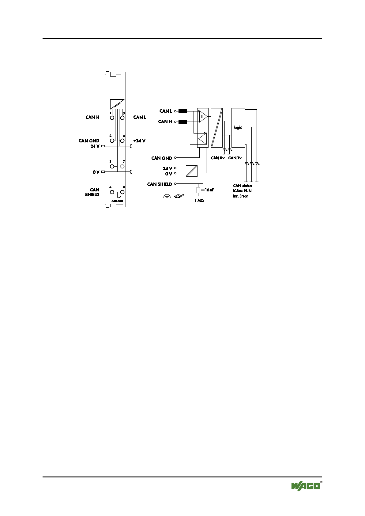
Table 7: Legend for Figure “CAGE CLAMP® Connectors”
Connection
Designation
Function
1
CAN-H
CAN High
2
CAN-GND
CAN Ground
3
0 V
Supply voltage 0 V
4
Shield
Shield (screen)
5
CAN-L
CAN Low
6
+24 V
Supply voltage + 24 V
7
N.C.
-not connected-
8
Shield
Shield (screen)
750-658 CAN Gateway
Pos: 36 /Ser ie 75 0 (WA GO-I/ O-SYS TEM )/ Ger äteb esc hrei bu ng/A nsc hlüs se/ CAG E CL AMP- An schl üss e - Üb ersc hrif t 3 @ 6 \mod_1256296337770_21.docx @ 43674 @ 3 @ 1
4.2.3 CAGE CLAMP® Connectors
Pos: 37 /Ser ie 75 0 (WA GO-I/ O-SYS TEM )/ Ger äteb esc hrei bu ng/A nsc hlüs se/ So nder kle mme n/A nschl üs se C C 75 0-0658 @ 14\mod_1358431143982_21.docx @ 108895 @ @ 1
Figure 4: CAGE CLAMP
®
Connectors
Pos: 38 /Ser ie 75 0 (WA GO-I/ O-SYS TEM) /Wic htige Er läut erunge n/Si cherh eits- u nd sonstige Hinweise/Hinweis/Hinweis: Geschirmte Signal leit ung en ver wend en! @ 7 \mod_1265723251019_21.docx @ 50140 @ @ 1
Use shielded signal lines!
Only use shielded signal lines for analog signals and I/O modules which are
equipped with shield clamps. Only then can you ensure that the accuracy and
interference immunity specified for the respective I/O module can be achieved
even in the presence of interference acting on the signal cable.
Pos: 39 /Dokum entati on allg emei n/Gli ederung sele mente /---Seit enwe chs el--- @ 3\mod_1221108045078_0.docx @ 21810 @ @ 1
Manual
Version 1.2.0, valid from FW/HW-Version 01/01
Page 22
22 Device Description WAGO-I/O-SYSTEM 750
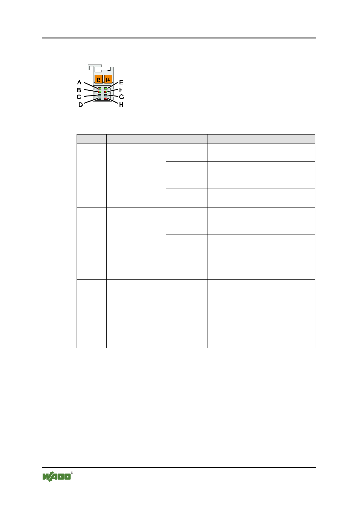
Table 8: Legend for Figure “Display Elements”
LED
Designation
Status
Function
Error on the CAN bus. CAN bus
not initialized.
green
CAN bus properly initialized.
CAN telegram could not be
received.
green
CAN telegram received.
C
not assigned - -
D
not assigned - -
Data exchange via mailbox or
register communication possible.
Data exchange via mailbox or
possible.
red
CAN telegram could not be sent.
green
CAN telegram sent.
G
not assigned - -
Internal error:
error
750-658 CAN Gateway
Pos: 40 /All e S eri en ( Allg emei n e Mod ule) /Ü ber schri fte n/ Ebe ne 2/ Anz eig eel eme nte - Ü b erschr if t 2 @ 4 \mod_1240984390875_21.docx @ 31964 @ 2 @ 1
4.3 Display Elements
Pos: 41 /Ser ie 75 0 (WA GO-I/ O-SYS TEM )/ Gerät ebes chr eibu ng/A nz eige elem ente /Son der kle mmen /Anz eigeel eme nte 750- 0658 @ 14\mod_1358501741773_21.docx @ 108920 @ @ 1
Figure 5: Display Elements
A CAN status
B CAN-Rx
red
red
green
E
Internal data bus
RUN
off
F CAN-Tx
H Int. ERROR red
register communication not
• Buffer overflow
• Error in mailbox
communication
• Parameter channel error
• Register communication
Pos: 42 /Dokum entati on allg emei n/Gli ederung sele mente/---Seiten wechs el--- @ 3\mod_1221108045078_0.docx @ 21810 @ @ 1
Manual
Version 1.2.0, valid from FW/HW-Version 01/01
Page 23
WAGO-I/O-SYSTEM 750 Device Description 23
750-658 CAN Gateway
Pos: 43 /All e S eri en ( Allg emei n e Mod ule) /Ü ber schri fte n/ Ebe ne 2/ Sc hemat is ches Sc halt bild - Ü bersc hrift 2 @ 4\ mod_1240984441312_21.docx @ 31967 @ 2 @ 1
4.4 Schematic Diagram
Pos: 44 /Ser ie 750 (WAGO-I/O-SYSTEM )/ Ger äteb esc hrei bu ng/S ch emat isc he Sc h altbil der /S ond erkl em men/ Sche mati sc hes Sc halt bild 75 0-0 658 @ 14\ mod_1361883149925_21.doc x @ 112965 @ @ 1
Figure 6: Schematic Diagram
Pos: 45 /Dokum entati on allg emei n/Gli ederung sele mente /---Seit enwe chs el--- @ 3\mod_1221108045078_0.docx @ 21810 @ @ 1
Manual
Version 1.2.0, valid from FW/HW-Version 01/01
Page 24

24 Device Description WAGO-I/O-SYSTEM 750
Table 9: Technical Data – Device
Width
12 mm/0.472 in.
Height (from upper edge of DIN 35 rail)
64 mm
Length
100 mm
Weight
approx. 55 g
Degree of protection
IP20
Data width, internal
8 bytes
48 bytes
Table 10: Technical Data ‒ Supply
Power supply
Via system voltage internal bus (5 V
DC)
Current consumption, system voltage
(5 V DC)
50 mA
Current consumption
(24 V DC)
12 mA
Voltage via power jumper contacts
24 V DC
(supply via e.g. 750-625)
Current via power jumper contacts
max.
10 A
Power consumption P
max.
circa 0.5 W
Isolation (peak value)
500 V DC system / supply
750-658 CAN Gateway
Pos: 46 /All e S eri en ( Allg emei n e Mod ule) /Ü ber schri fte n/ Ebe ne 2/ Tec hni sch e Dat en - Über sc hrift 2 @ 3\ mod_1232967587687_21.docx @ 26924 @ 2 @ 1
4.5 Technical Data
Pos: 47 /Ser ie 75 0 (WA GO-I/ O-SYS TEM )/ Ger äteb esc hrei bu ng/T ech nisc he D ate n/ Son derkl e mmen/T ec hni sch e D ate n 75 0-065 8 @ 14\mod_1358511761305_21.docx @ 108951 @ 333 @ 1
4.5.1 Device Data
12 bytes
16 bytes
20 bytes
24 bytes
32 bytes
40 bytes
4.5.2 Supply
DC) and power jumper contacts (24 V
typ.
max.
Manual
Version 1.2.0, valid from FW/HW-Version 01/01
Page 25

WAGO-I/O-SYSTEM 750 Device Description 25
Table 11: Technical Data – CAN Communication
Baud rate CAN
10 kBit/s
Auto baud rate
Diagnostic information
Internal bus status via status byte,
event codes via the mailbox
Table 12: Technical Data – Field Wiring
Wire connection
CAGE CLAMP®
Cross section
0.08 mm² … 2.5 mm², AWG 28 … 14
Stripped lengths
8 mm … 9 mm / 0.33 in
Table 13: Technical Data – Power Jumper Contacts
Power jumper contacts
Blade/spring contact, self-cleaning
Table 14: Technical Data – Data Contacts
Data contacts
Slide contact, hard gold plated, selfcleaning
Table 15: Technical Data – Climatic Environmental Conditions
Operating temperature range
0 °C … 55 °C
Storage temperature range
−25 °C … +85 °C
Relative humidity without condensation
Max. 95 %
Resistance to harmful substances
Acc. to IEC 60068-2-42 and
IEC 60068-2-43
Maximum pollutant concentration at
SO2 ≤ 25 ppm
H2S ≤ 10 ppm
Special conditions
Ensure that additional measures for
– ionizing radiation
750-658 CAN Gateway
4.5.3 CAN Communication
20 kBit/s
50 kBit/s
125 kBit/s
250 kBit/s
500 kBit/s
800 kBit/s
1000 kBit/s
Pos: 48.1 /Al l e Ser ien ( Al lge mei ne M od ule)/Ü ber sc hrift e n/Eb ene 3/A nsc hluss te chni k - Überschrift 3 @ 17\mod_1380123271324_21.docx @ 132788 @ 3 @ 1
4.5.4 Connection Type
Pos: 48.2 /Serie 750 (WAGO-I/O-S YST EM) /Ger äte bes chr ei bung /T echni sc he Da ten/ A nsc hluss tec hni k/T echni sc he D at en V erdr aht ung sebe ne C C - 0,0 8 bis 2,5 mm2 @ 17\ mod_1380121238809_21.docx @ 132780 @ @ 1
Pos: 48.3 /Serie 750 (WAGO-I/O-S YST EM) /Ger äte bes chr ei bung /T echni sc he Da ten/ A nsc hluss tec hni k/T echni sc he D at en L eist ungs ko nta kte ( Mes ser/ Fe der) @ 19\ mod_1400241643293_21.docx @ 153921 @ @ 1
Pos: 48.4 /Serie 750 (WAGO-I/O-S YST EM) /Ger äte bes chr ei bung /T echni sc he Da ten/ A nsc hluss tec hni k/T echni sc he D at en Da te nkon tak te @ 17\ mod_1380123495844_21.docx @ 132 794 @ @ 1
Pos: 49 /Ser ie 75 0 (WA GO-I/ O-SYS TEM )/ Ger äteb esc hrei bu ng/T ech nisc he D ate n/ Kli mati sch e Umg eb ungs bedi ng ung en/T ech nisc he Da ten Klim at. Umg ebung sbed. ohne er w. Tem p. 0... 55°C/-2 5... +85° C @ 5\ mod_1247657968368_21.docx @ 37603 @ 3 @ 1
4.5.5 Climatic Environmental Conditions
Pos: 50 /Dokum entati on allg emei n/Gli ederung sele mente /---Seitenwechsel--- @ 3\mod_1221108045078_0.docx @ 21810 @ @ 1
relative humidity < 75 %
components are taken, which are used in
an environment involving:
– dust, caustic vapors or gases
Manual
Version 1.2.0, valid from FW/HW-Version 01/01
Page 26
26 Device Description WAGO-I/O-SYSTEM 750
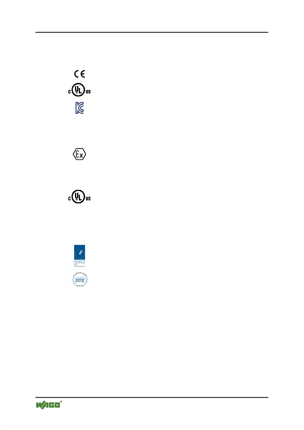
Conformity Marking
TÜV 14 ATEX 148929 X
II 3 G Ex nA IIC T4 Gc
IECEx TUN 14.0035 X
Ex nA IIC T4 Gc
CULUS
ANSI/ISA 12.12.01
Class I, Div2 ABCD T4
750-658 CAN Gateway
Pos: 51 /All e S eri en ( Allg emei n e Mod ule) /Ü ber schri fte n/ Ebe ne 2/ Zul ass ung en - Ü bersc hrift 2 @ 3\mod_1224055364109_21.docx @ 24030 @ 2 @ 1
4.6 Approvals
Pos: 52 /Ser ie 75 0 (WA GO-I/ O-SYS TEM )/ Gerät ebes chr eibu ng/Z ulas su nge n/ Allg emei n/Z ulass u nge n Bus kl emme 75 0-x xxx Allg emein, ohne Var iant enang abe - Einl eit ung @ 4\mod_1237460656921_21.docx @ 28643 @ @ 1
The following approvals have been granted to 750-658 I/O modules:
Pos: 53 /Alle Serien (Allgemeine Module)/Zulassungen/Standardz ulassungen/CE (Konformitätskennzeichnung) @ 3\mod_1224494777421_21.docx @ 24276 @ @ 1
Pos: 54 /All e S eri en ( Allg emei n e Mod ule) /Z ulas sung en/ St and ardz ula ssu nge n/cU Lus ( U L50 8) @ 3\mod_1224055013140_0.docx @ 24020 @ @ 1
Pos: 55 /All e S eri en ( Allg emei n e Mod ule) /Z ulas sung en/ St and ardz ula ssu nge n/KC - Kor ea Cer tifi cat e - MSM @ 23\mod_1435133798551_21.docx @ 184462 @ @ 1
Pos: 56 /Dokum entati on allg emei n/Gli ederung sele mente /---Leera bs atz-( 2Z)--- @ 3 \mod_1224662755687_0.docx @ 24460 @ @ 1
Pos: 57 /Ser ie 75 0 (WA GO-I/ O-SYS TEM )/ Gerät ebes chr eibu ng/Z ulass unge n/Ex/Z ulass unge n Buskle mme 75 0-xxxx Ex, ohne Variantenangabe - Einleitung @ 4\mod_1237191218000_21.docx @ 28423 @ @ 1
The following Ex approvals have been granted to 750-658 I/O modules:
Pos: 58.1 /All e Serien ( Al lge mei ne M od ule)/Z ul assu nge n/ Ex-Zulassungen/TÜV ATEX/TÜV 14 ATEX 148929 X: II 3 G Ex nA IIC T4 Gc @ 21\mod_1416987498312_0.docx @ 169048 @ @ 1
Pos: 58.2 /Al l e Ser ien ( Al lge mei ne M od ule)/Z ul assu nge n/ Ex-Zul ass u ngen /IEC Ex (TÜ V Nor d) /IEC Ex TUN 14 .003 5 X: Ex nA IIC T 4 Gc @ 21 \mod_1416987779897_0.docx @ 169052 @ @ 1
Pos: 58.3 /Al l e Ser ien ( Al lge mei ne M od ule)/Z ul assu nge n/ Ex-Zul ass u ngen /cU Lus /cU Lus ( AN SI/I SA 12.1 2.01) Cl ass I, Di v2 A BCD T 4 @ 3\ mod_1224054791812_0.docx @ 24014 @ @ 1
Pos: 58.4 /Dokumentation allgemein/Glieder ungselemente/----Leerzeile-(1Z)---- @ 28\mod_1485262995837_0.docx @ 404006 @ @ 1
Pos: 59 /Dokum entati on allg emei n/ Glie derung s elem ente /---Leer abs atz-( 2Z) --- @ 3\mod_1224662755687_0.docx @ 24460 @ @ 1
Pos: 60 /Ser ie 75 0 (WA GO-I/ O-SYS TEM) /Ger ätebes chrei bung /Zulass ung en/Sc hiff/ Einl eitungs sätz e/Zulas sung en Bus klem me 750- xxxx Sc hiff, oh ne Vari ante nanga be - Einl eitung @ 4\mod_1237190918453_21.docx @ 28420 @ @ 1
The following ship approvals have been granted to 750-658 I/O modules:
Pos: 61 /All e S eri en ( Allg emei n e Mod ule) /Z ulas sung en/ Sc hiffs zul ass ung en/ BSH (B und esam t für Se esc hiff fahr t u nd H ydr ogr aphi e) @ 5\ mod_1246341825156_21.docx @ 36334 @ @ 1
CULUS
UL508
Korea Certification MSIP-REM-W43-MSM750
Federal Maritime and Hydrographic Agency
Pos: 62 /All e S eri en ( Allg emei n e Mod ule) /Z ulas sung en/ Sc hiffs zul ass ung en/ GL ( Ger ma nisc her Llo yd) C at . A, B, C , D ( EM C 1) @ 3\mod_1224492724484_0.docx @ 24228 @ @ 1
GL (Germanischer Lloyd) Cat. A, B, C, D (EMC 1)
Pos: 63 /Dokum entati on allg emei n/Gli ederung sele mente /---Seit enwe chs el--- @ 3\mod_1221108045078_0.docx @ 21810 @ @ 1
Manual
Version 1.2.0, valid from FW/HW-Version 01/01
Page 27

WAGO-I/O-SYSTEM 750 Device Description 27
750-658 CAN Gateway
Pos: 64 /All e S eri en ( Allg emei n e Mod ule) /Ü ber schri fte n/ Ebe ne 2/ Nor men und Ri chtl inie n - Ü bersc hrift 2 @ 4\mod_1242804031875_21.docx @ 33646 @ 2 @ 1
4.7 Standards and Guidelines
Pos: 65 /Ser ie 75 0 (WA GO-I/ O-SYS TEM )/ Ger äteb esc hrei bu ng/N orm en u nd R ic htlini e n/EM V-Nor m en B uskl e mme 7 50-x xxx, ohn e Vari anten angab e - Einl eitung @ 4\mod_1242803944015_21.docx @ 33642 @ @ 1
750-658 I/O modules meet the following requirements on emission and immunity
of interference:
Pos: 66 /All e S eri en ( Allg emei n e Mod ule) /N or men un d Ri chtl i nien/ EM V-N orme n - St andar d/ EMV CE- Stör fest igk eit EN 61000-6-2 @ 4\mod_1242797655625_21.docx @ 33591 @ @ 1
EMC CE-Immunity to interference EN 61000-6-2
Pos: 67 /All e S eri en ( Allg emei n e Mod ule) /N or men un d Ri chtl i nien/ EM V-N orme n - St andar d/ EMV CE- Stör festi gkeit EN 6113 1-2 @ 5\mod_1245337216375_21.docx @ 35650 @ @ 1
EMC CE-Immunity to interference EN 61131-2
Pos: 68 /All e S eri en ( Allg emei n e Mod ule) /N or men un d Ri chtl i nien/ EM V-N orme n - St andar d/ EMV CE- Störaussendung EN 61000-6-3 + A1 @ 27\mod_1467095722426_21.docx @ 214858 @ @ 1
EMC CE-Emission of interference EN 61000-6-3 + A1
Pos: 69 /All e S eri en ( Allg emei n e Mod ule) /N or men un d Ri chtl i nien/ EM V-N orme n - St andar d/ EMV CE- Störaussendung EN 61131-2 @ 6\mod_1259753022195_21.docx @ 46410 @ @ 1
EMC CE-Emission of interference EN 61131-2
Pos: 70 /Dokumentation allgemein/Gl ieder ung sele me nte/---Sei te nwec hsel --- @ 3\mod_1221108045078_0.docx @ 21810 @ @ 1
Manual
Version 1.2.0, valid from FW/HW-Version 01/01
Page 28
28 Function Description WAGO-I/O-SYSTEM 750
750-658 CAN Gateway
Pos: 71.1 /Al l e Ser ien ( Al lge mei ne M od ule)/Ü ber sc hrift e n/Eb ene 1/F un ktion sb eschr ei bung - Ü bersc hri ft 1 @ 4\mod_1239025975389_21.docx @ 30003 @ 1 @ 1
5 Function Description
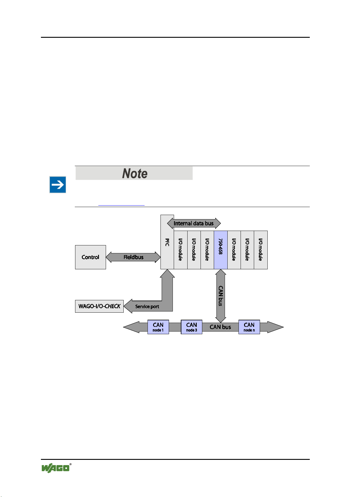
Pos: 71.2 /Serie 750 (WAGO-I/O-S YSTEM )/F unktio nsbes chrei bung /Fun ktionsb eschr eibu ng 750-0658 - Ei nleit ung @ 13\mod_1355737974549_21.docx @ 107690 @ @ 1
The I/O module has the following functions:
• CAN telegrams that contain user data can be copied to the process image of
the input.
• Received CAN telegrams can be transferred to the controller.
• CAN telegrams can be sent to other CAN nodes.
• Specific CAN bus diagnostics can be displayed.
The data can be transferred by the "Mailbox 2.0" protocol among others.
Use Mailbox 2.0!
Use IEC-61131 compliant function blocks to use Mailbox 2.0. You can download
them at www.wago.com.
Figure 7: Functional Description 750-658
Pos: 71.3 /Al l e Ser ien ( Al lge mei ne M od ule)/Ü ber sc hrift e n/Eb ene 2/B etri ebs arte n - Ü ber schr if t 2 @ 13\ mod_1355740360138_21.docx @ 107697 @ 2 @ 1
5.1 Operating Modes
Pos: 71.4 /Serie 750 (WAGO-I/O-S YSTEM )/F unktio nsbes chrei bung /Fun ktionsb eschr eibu ng 750-0658 - Üb ersic ht der Betr iebs arten @ 14\mod_1360311385982_21.docx @ 111210 @ @ 1
The I/O module can be operated in the following three modes:
• Sniffer mode
• Transparent mode
• Mapped mode
Pos: 71.5 /Serie 750 (WAGO-I/O-S YSTEM )/F unktio nsbes chrei bung /Fun ktionsb eschr eibu ng 750-0658 - Betr ie bsar ten @ 13\mod_1355758147324_21.docx @ 107750 @ 3334455554 @ 1
Manual
Version 1.2.0, valid from FW/HW-Version 01/01
Page 29
WAGO-I/O-SYSTEM 750 Function Description 29
750-658 CAN Gateway
5.1.1 Sniffer Mode
In "Sniffer mode", the I/O module is a passive node in the bus network. That
means that the transmitter is deactivated from the hardware side. In this operating
mode telegrams can only be sent and not sent in principle.
If CAN telegrams are received, no confirmation is sent to the sender.
Confirmation must be handled by a third node. At least two other CAN nodes
must be available. Received telegrams are transferred to the higher-level
controller via the "Mailbox 2.0" transmission protocol.
5.1.2 Transparent Mode
In "Transparent mode", the I/O module is an active node in the bus network. That
means that the transmitter is activated from the hardware side. In this operating
mode, telegrams can be received and sent.
If CAN telegrams are received, confirmation is sent to the sender. Received
telegrams are transferred to the higher-level controller via that "Mailbox 2.0"
transmission protocol.
5.1.3 Mapped Mode
The "Mapped mode" is fundamentally different from the other two modes. In this
operating mode, incoming and outgoing CAN telegrams can be mapped to the
process image without any protocol. Only user data and no control data is
mapped.
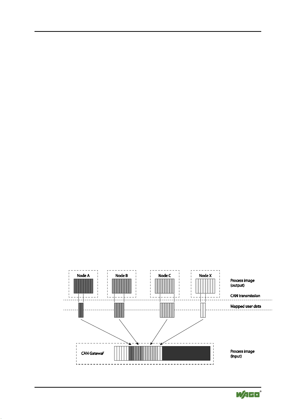
5.1.3.1 Map CAN Telegrams in Input Direction
Up to 44 bytes can be configured in the process image of the input. During
configuration, CAN telegrams can be selected from which a user data byte should
be mapped. A more detailed description is available in the "Process Image"
section.
Figure 8: Map CAN Telegrams in Input Direction
Manual
Version 1.2.0, valid from FW/HW-Version 01/01
Page 30
30 Function Description WAGO-I/O-SYSTEM 750
750-658 CAN Gateway
Once a CAN telegram is received, the bytes in question are updated in the process
image of the input with the respective data.
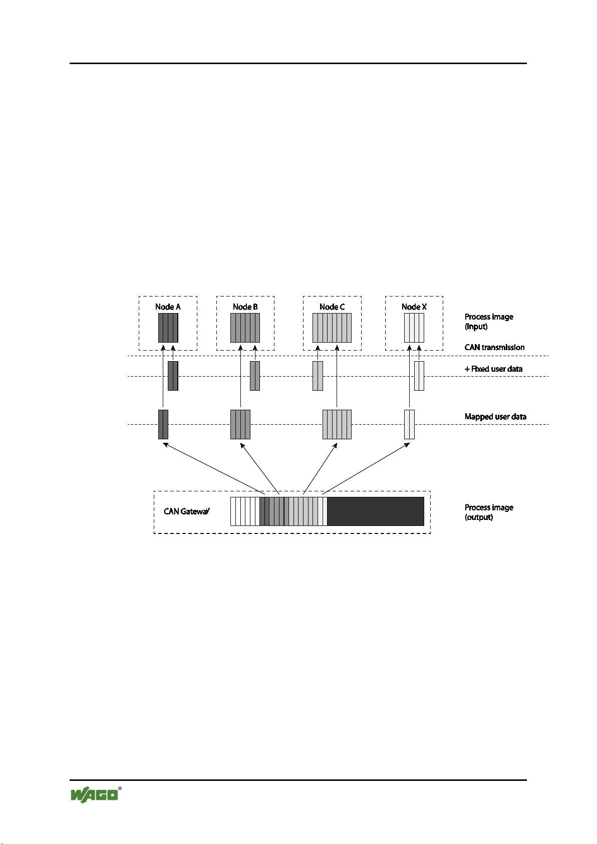
5.1.3.2 Map CAN Telegrams in Output Direction
CAN telegrams can also be mapped in the output direction. However, it is
somewhat more complex because individual settings are required for each
telegram before it can be sent. When a configured CAN telegram is sent also
depends on the trigger configuration. The following settings are possible:
• Send on request
• Send on change
• Cycle time
Figure 9: Map CAN Telegrams in Output Direction
5.1.3.2.1 "Content of the CAN telegram" Setting
The content of the CAN telegram to send can be set in addition to the trigger. The
following settings are possible:
"Identifier extension bit" (IDE) Setting
The "Identifier extension bit" (IDE) can be used to set whether the output
telegram should be one of the following:
• "2.0A Standard Frame"
• "2.0B Extended Frame"
Manual
Version 1.2.0, valid from FW/HW-Version 01/01
Page 31

WAGO-I/O-SYSTEM 750 Function Description 31
Table 16: Toggle Byte
Bit 7
Bit 6
Bit 5
Bit 4
Bit 3
Bit 2
Bit 1
Bit 0
Toggle byte
Group 8
Group 7
Group 6
Group 5
Group 4
Group 3
Group 2
Group 1
750-658 CAN Gateway
For a "2.0A Standard Frame", 211 (7FFh) is the largest possible CAN ID and for
"2.0B Extended Frame", 229 (1FFFFFFF) is the largest.
"Remote Transmission Request" (RTR) Setting
The "Remote Transmission Request" bit can used to set whether the mapped CAN
output frame involves a so-called "remote request" or a data frame.
"Data Length Code" (DLC) Setting
The "Data Length Code" (DLC) can be used to specify how many user data bytes
there should be in the CAN telegram.
The user data bytes do not have to match the mapped bytes on the process image
in terms of quantity. A fixed value can be specified for all non-mapped data bytes.
Fixed values can be specified for data storage areas that have been defined in the
DLC, but not mapped variably in the process image. These values are then
automatically copied to the user data when a telegram in the output direction is
generated.
5.1.3.2.2 "Send on request" Setting
In this setting, CAN telegrams are send via the so-called "toggle byte" in the
process image. Send groups can be assigned to telegrams to be sent.
If one or more bits are inverted in the toggle byte, the respective send groups are
affected. All assigned telegrams are created and sent.
The I/O module then confirms transmission by inverting the associated bit of the
toggle byte in the process image of the input.
If several send groups are selected, they are sent one after the other: Group 1 has
the highest send priority, Group 8 has the lowest.
5.1.3.2.3 "Send on change" Setting
If this setting is enabled, the CAN telegram is sent when a mapped byte has been
sent. The mapped and fixed values are applied.
5.1.3.2.4 "Cycle Time" Setting
Manual
Version 1.2.0, valid from FW/HW-Version 01/01
A cycle time can be set for each CAN telegram to sent. The telegram is then
created and sent repeatedly by the I/O module. The time interval between two
transmissions is the cycle time. It can also be a telegram that contained no data
from the process image of the output, rather fixed values only.
Page 32

32 Function Description WAGO-I/O-SYSTEM 750
750-658 CAN Gateway
5.1.3.3 Access CAN Telegrams via the Mailbox
CAN telegrams of a defined range can also be received and sent via the mailbox.
The data format is identical to the data formats of the "Sniffer" and "Transparent"
operating modes.
Note modified access times!
Communication via the mailbox is slower, but it is possible in this option to
access selected CAN telegrams acyclically (e.g. comparable to "SDO" and
"EMCY" functionalities).
Pos: 71.6 /Dokumentation allgemein/Glieder ungselemente/---Seitenwechsel--- @ 3\mod_1221108045078_0.docx @ 21810 @ @ 1
Manual
Version 1.2.0, valid from FW/HW-Version 01/01
Page 33

WAGO-I/O-SYSTEM 750 Function Description 33
750-658 CAN Gateway
Pos: 71.7 /Al l e Ser ien ( Al lge mei ne M od ule)/Ü ber sc hrift e n/Eb ene 2/F ilter ei nstel l unge n - Ü bersc hrift 2 @ 14\ mod_1358176336838_21.docx @ 108633 @ 2 @ 1
5.2 Filter Settings
Pos: 71.8 /Serie 750 (WAGO-I/O-S YSTEM )/F unktio nsbes chrei bung /Fun ktionsb eschr eibu ng 750-0658 - Fil ter eins tell ung en @ 1 4\mod_1358176214506_21.docx @ 108630 @ 33 @ 1
With 6 configurable pass-through filters, the bandwidth of the CAN telegrams for
the user transmitted to the controller can be limited to specific ranges. This saves
resources on the control level and in the I/O module.
A CAN ID can be specified for the upper and lower limits per filter. The value of
the upper limit must be greater than or equal to the value of the lower limit.
Otherwise, the I/O module will output an error message. Only the telegrams are
transmitted that fall within the filter limits.
Transmission of CAN telegrams from the I/O module to the controller can take
more time than receiving these telegrams on the CAN bus. Thus, several CAN
telegram of the same CAN ID may be cached in the I/O module. The following
settings can be made:
1. "Overwrite"
2. "Keep All"
5.2.1 "Overwrite" Setting
If this setting is selected, newly received telegrams are overwritten when
telegrams of the same CAN ID are received. This requires that the received
telegram has not yet been forwarded to the controller. The system workload can
be reduced significantly.
Do not select "Overwrite" for protocol data!
The "Overwrite" setting should not be selected when protocol data of higher
layers (e.g. SDOs, etc.) is transmitted. It may be unusable because all data of a
CAN ID is required in general. Select the "Keep All" setting here.
5.2.2 "Keep All" Setting
If this setting is selected, received telegrams are not overwritten, rather forwarded
to the controller sequentially. Only use this setting when data usage of received
CAN telegrams is low.
Pos: 72 /Dokum entati on allg emei n/Gli ederung sele mente /---Seit enwe chs el--- @ 3\mod_1221108045078_0.docx @ 21810 @ @ 1
Manual
Version 1.2.0, valid from FW/HW-Version 01/01
Page 34

34 Process Image WAGO-I/O-SYSTEM 750
Table 17: Control Byte
Control byte
Bit 7
Bit 6
Bit 5
Bit 4
Bit 3
Bit 2
Bit 1
Bit 0
0
res.*
res.*
res.*
res.*
res.*
res.*
res.*
0 = Read register
1 = Write register
* Reserved
Table 18: Status Byte
Status byte
Bit 7
Bit 6
Bit 5
Bit 4
Bit 3
Bit 2
Bit 1
Bit 0
0
GEN_
ERR
CAN_
ERR
TX_
OVF
RX_
OVF
INT_
ERR
1
Res.
Register number
(Bit 7)
0
Mailbox 0 active
1
Register communication enabled
GEN_ERR
0
No error on the CAN Bus.
1
Error on the CAN bus. Set when one of the bits 0…5 = 1.
CAN_ERR
0
No error on the CAN Bus.
1
Error on the CAN bus.
TX_OVF
0
Send buffer OK.
1
Send buffer overflow (downstream). No data can be received by the I/O module.
RX_OVF
0
Receive buffer OK.
1
Receive buffer overflow (upstream). No data can be received by the I/O module.
INT_ERR
0
No internal error.
1
Internal error. Possible causes:
• Faulty register request
750-658 CAN Gateway
Pos: 73 /Ser ie 75 0 (WA GO-I/ O-SYS TEM )/ Proz ess abbi ld Kle mme nbus /S ond er klemm en/P roz ess ab bild 750- 0658 @ 14\mod_1358254522792_21.docx @ 108700 @ 12332332333 @ 1
6 Process Image
The first byte of the internal bus process image is:
• The control byte in the process output direction
• The status byte in the process input direction
The mailbox is static in the process image and is cross-faded when register
communication is on.
During register communication, the register query response is contained in the
status byte followed by 2 bytes of register data.
If the mailbox is active, status information of the I/O module is displayed
cyclically via the status byte.
Control byte
1
Register number
Status byte
• 24V field supply missing
• Communication via mailbox and process data faulty
• Faulty parameterization request
Manual
Version 1.2.0, valid from FW/HW-Version 01/01
Page 35

WAGO-I/O-SYSTEM 750 Process Image 35
750-658 CAN Gateway
6.1 Process Image in "Sniffer" Operating Mode
The CAN user data range on the process image is symmetrical for both data
directions.
Figure 10: Process Image in "Sniffer" Mode
6.1.1 Mailbox
Modules with mailbox functionality have an acyclic communication channel
(mailbox) in the process image. The "Mailbox 2.0" (referred to below as
"mailbox") transmission method is the basis.
If the Mailbox is active (control byte, bit 7 = 0), it is used to transfer
configuration, parameterization and diagnostic data. Byte 1 to byte 6 of the
internal process image are used by default. Additional information about the
"Mailbox 2.0 Transmission Method" is available in the respective chapter in the
appendix.
6.1.2 CAN User Data Range
The CAN user data range is a fixed component of the "Sniffer" and "Transparent"
operating modes (see respective chapter). CAN telegrams are transmitted via the
"Mailbox 2.0" communication mechanism. The mechanism supports the
following two types of telegrams:
• "2.0A Standard Frame"
• "2.0B Extended Frame"
Manual
Version 1.2.0, valid from FW/HW-Version 01/01
Page 36

36 Process Image WAGO-I/O-SYSTEM 750
Table 19: Structure of CAN Telegrams with the "2.0A Standard Frame" Setting
Byte
Name
Bits
Identifier
byte 1
Identifier
byte 2
2
Data
TR/RX Data Byte 1
3
Data
TR/RX Data Byte 2
4
Data
TR/RX Data Byte 3
5
Data
TR/RX Data Byte 4
6
Data
TR/RX Data Byte 5
7
Data
TR/RX Data Byte 6
8
Data
TR/RX Data Byte 7
9
Data
TR/RX Data Byte 8
Table 20: Structure of CAN Telegrams with the "2.0B Extended Frame" Setting
Byte
Name
Bits
Identifier
byte 1
Identifier
byte 2
Identifier
byte 3
Identifier
byte 4
Identifier
byte 5
5
Data
TR/RX Data Byte 1
6
Data
TR/RX Data Byte 2
7
Data
TR/RX Data Byte 3
8
Data
TR/RX Data Byte 4
9
Data
TR/RX Data Byte 5
10
Data
TR/RX Data Byte 6
11
Data
TR/RX Data Byte 7
12
Data
TR/RX Data Byte 8
750-658 CAN Gateway
If the "2.0A Standard Frame" is activated, CAN telegrams have the following
structure:
0
1
ID.10 ID.9 ID.8 ID.7 ID.6 ID.5 ID.4 ID.3
ID.2 ID.1 ID.0 RTR DLC.3 DLC.2 DLC.1 DLC.0
If the "2.0B Extended Frame" setting is activated, CAN telegrams have the
following structure:
0
RES RES RES ID.28 ID.27 ID.26 ID.25 ID.24
1
2
3
4
ID.23 ID.22 ID.21 ID.20 ID.19 ID.18 ID.17 ID.16
ID.15 ID.14 ID.13 ID.12 ID.11 ID.10 ID.9 ID.8
ID.7 ID.6 ID.5 ID.4 ID.3 ID.2 ID.1 ID.0
IDE RTR RES RES DLC.3 DLC.2 DLC.1 DLC.0
The actual length of the data to be transmitted is based on the length of the user
data. It may vary.
Manual
Version 1.2.0, valid from FW/HW-Version 01/01
Page 37

WAGO-I/O-SYSTEM 750 Process Image 37
750-658 CAN Gateway
6.2 Process Image in "Transparent" Operating Mode
The CAN user data range on the process image is symmetrical for both data
directions.
Figure 11: Process Image in the "Transparent" Operating Mode
6.2.1 Mailbox
See chapter "Mailbox" in the "Sniffer" operating mode.
6.2.2 CAN User Data Range
See chapter "CAN User Data Range" in the "Sniffer" operating mode.
Manual
Version 1.2.0, valid from FW/HW-Version 01/01
Page 38

38 Process Image WAGO-I/O-SYSTEM 750
Table 21: Toggle Byte
Bit 7
Bit 6
Bit 5
Bit 4
Bit 3
Bit 2
Bit 1
Bit 0
Toggle byte
Group 8
Group 7
Group 6
Group 5
Group 4
Group 3
Group 2
Group 1
750-658 CAN Gateway
6.3 Process Image in the "Mapped" Operating Mode
Figure 12: Process Image in the "Mapped" Operating Mode
6.3.1 Mailbox
See chapter "Mailbox" in the "Sniffer" operating mode.
6.3.2 Toggle Byte
The toggle byte is a fixed component of the "Mapped" operating mode (see
respective chapter). It is one byte and is used to send CAN telegrams on request.
If one or more bits are inverted, the respective send groups are affected. All
assigned telegrams are created and sent. The toggle byte is behind the last byte of
the mailbox.
6.3.3 Mapped Cyclical Data (CAN User Data)
The mapped user data D0 to D7 of all configured CAN telegrams is found within
this range.
Pos: 74 /Dokum entati on allg emei n/Gli ederung sele mente /---Seit enwe chs el--- @ 3\mod_1221108045078_0.docx @ 21810 @ @ 1
Manual
Version 1.2.0, valid from FW/HW-Version 01/01
Page 39

WAGO-I/O-SYSTEM 750 Mounting 39
750-658 CAN Gateway
Pos: 75 /All e S eri en ( Allg emei n e Mod ule) /Ü ber schri fte n/ Ebe ne 1/M o nti eren - Über sc hrift 1 @ 3\ mod_1225446744750_21.docx @ 24900 @ 1 @ 1
7 Mounting
Pos: 76.1 /Serie 750 (WAGO-I/O-S YST EM)/ Mon tier en/D em onti eren/M o ntag erei henfol ge @ 3\mod_1231770210031_21.docx @ 25992 @ 2 @ 1
7.1 Mounting Sequence
Fieldbus couplers/controllers and I/O modules of the WAGO-I/O-SYSTEM 750
are snapped directly on a carrier rail in accordance with the European standard EN
50022 (DIN 35).
The reliable positioning and connection is made using a tongue and groove
system. Due to the automatic locking, the individual devices are securely seated
on the rail after installation.
Starting with the fieldbus coupler/controller, the I/O modules are mounted
adjacent to each other according to the project design. Errors in the design of the
node in terms of the potential groups (connection via the power contacts) are
recognized, as the I/O modules with power contacts (blade contacts) cannot be
linked to I/O modules with fewer power contacts.
Pos: 76.2 /Serie 750 (WAGO-I/O-S YSTEM )/Wi chtig e Erlä uteru ngen/ Sicher heits- und so nstig e H inw eis e/Vor sic ht/ Vor sic ht: Verl etz ungs ge fahr dur ch s ch arf kant ige M ess er kont akt e! @ 6\mod_1256193279401_21.docx @ 43414 @ @ 1
Risk of injury due to sharp-edged blade contacts!
The blade contacts are sharp-edged. Handle the I/O module carefully to prevent
injury.
Pos: 76.3 /Serie 750 (WAGO-I/O-S YSTEM )/Wi chtig e Erlä uteru ngen/ Sicher heits- und sonstige Hinweise/Achtung/Achtung: Busklemmen nur in vorg eseh ener R eih enfolg e s tec ke n! @ 6\mod_1256194177073_21.docx @ 43429 @ @ 1
Insert I/O modules only from the proper direction!
All I/O modules feature grooves for power jumper contacts on the right side. For
some I/O modules, the grooves are closed on the top. Therefore, I/O modules
featuring a power jumper contact on the left side cannot be snapped from the top.
This mechanical coding helps to avoid configuration errors, which may destroy
the I/O modules. Therefore, insert I/O modules only from the right and from the
top.
Pos: 76.4 /Serie 750 (WAGO-I/O-S YSTEM )/Wi chtig e Erlä uteru ngen/ Sicher heits- und so nstig e H inw eis e/Hi nwei s/Hi n weis : Bu sa bschl us s ni cht ver gess en! @ 6 \mod_1256194225557_21.docx @ 43432 @ @ 1
Don't forget the bus end module!
Always plug a bus end module (750-600) onto the end of the fieldbus node! You
must always use a bus end module at all fieldbus nodes with WAGO-I/OSYSTEM 750 fieldbus couplers/controllers to guarantee proper data transfer.
Pos: 76.5 /Dokumentation allgemein/ Glie derungs ele mente /---Seite nwec hsel --- @ 3\mod_1221108045078_0.docx @ 21810 @ @ 1
Manual
Version 1.2.0, valid from FW/HW-Version 01/01
Page 40

40 Mounting WAGO-I/O-SYSTEM 750
750-658 CAN Gateway
Pos: 76.6 /Serie 750 (WAGO-I/O-S YST EM) /M onti ere n/D emon tier en/ Ger äte ein füg en u nd e nt fer nen - Ü ber schr if t 2 @ 3\ mod_1231768483250_21.doc x @ 25950 @ 2 @ 1
7.2 Inserting and Removing Devices
Pos: 76.7 /Al l e Ser ien ( Al lge mei ne M od ule)/ Sic herh eits - u nd s ons tig e Hi nweis e/ Ac htung /Ac htu ng: Arb eit en a n Ger ät en n ur s pan nung sfr ei d urc hf ühr en! @ 6\ mod_1256193963573_21.doc x @ 43426 @ @ 1
Perform work on devices only if they are de-energized!
Working on energized devices can damage them. Therefore, turn off the power
supply before working on the devices.
Pos: 76.8 /Serie 750 (WAGO-I/O-S YSTEM )/M ontier en/D emont ieren/ Bus klemme ei nfüg en @ 3\mod_1231769726703_21.docx @ 25989 @ 3 @ 1
7.2.1 Inserting the I/O Module
1. Position the I/O module so that the tongue and groove joints to the fieldbus
coupler/controller or to the previous or possibly subsequent I/O module are
engaged.
Figure 13: Insert I/O Module (Example)
2. Press the I/O module into the assembly until the I/O module snaps into the
carrier rail.
Figure 14: Snap the I/O Module into Place (Example)
With the I/O module snapped in place, the electrical connections for the data
contacts and power jumper contacts (if any) to the fieldbus coupler/controller or to
the previous or possibly subsequent I/O module are established.
Pos: 76.9 /Dokumentation allgemein/Glieder ungselemente/---Seitenwechsel--- @ 3\mod_1221108045078_0.docx @ 21810 @ @ 1
Manual
Version 1.2.0, valid from FW/HW-Version 01/01
Page 41

WAGO-I/O-SYSTEM 750 Mounting 41
750-658 CAN Gateway
Pos: 76.10 / Ser ie 750 ( WA GO-I/ O-SY STEM) /Monti ere n/De montier en/Bus kle mme ent ferne n @ 4\mod_1239169375203_21.docx @ 30334 @ 3 @ 1
7.2.2 Removing the I/O Module
1. Remove the I/O module from the assembly by pulling the release tab.
Figure 15: Removing the I/O Module (Example)
Electrical connections for data or power jumper contacts are disconnected when
removing the I/O module.
Pos: 77 /Dokum entati on allg emei n/Gli ederung sele mente /---Seit enwe chs el--- @ 3\mod_1221108045078_0.docx @ 21810 @ @ 1
Manual
Version 1.2.0, valid from FW/HW-Version 01/01
Page 42

42 Connect Devices WAGO-I/O-SYSTEM 750
750-658 CAN Gateway
Pos: 78 /All e S eri en ( Allg emei n e Mod ule) /Ü ber schri fte n/ Ebe ne 1/ Ger äte ans chl ieß en - Ü bersc hrift 1 @ 3\mod_1234172889468_21.docx @ 27460 @ 1 @ 1
8 Connect Devices
Pos: 79 /Ser ie 75 0 (WA GO-I/ O-SYS TEM )/ Ans chli eße n/L eiter a n CA GE C LAM P ansc hli eßen ( al lg emei n) - Ü bersc hrift 2 u nd Text @ 3\mod_1225448660171_21.docx @ 24928 @ 2 @ 1
8.1 Connecting a Conductor to the CAGE CLAMP®
The WAGO CAGE CLAMP® connection is appropriate for solid, stranded and
finely stranded conductors.
Only connect one conductor to each CAGE CLAMP®!
Only one conductor may be connected to each CAGE CLAMP®.
Do not connect more than one conductor at one single connection!
If more than one conductor must be routed to one connection, these must be
connected in an up-circuit wiring assembly, for example using WAGO feedthrough terminals.
1. For opening the CAGE CLAMP® insert the actuating tool into the opening
above the connection.
2. Insert the conductor into the corresponding connection opening.
3. For closing the CAGE CLAMP® simply remove the tool. The conductor is
now clamped firmly in place.
Figure 16: Connecting a Conductor to a CAGE CLAMP
Pos: 80 /Dokum entati on allg emei n/Gli ederung sele mente /---Seit enwe chs el--- @ 3\mod_1221108045078_0.docx @ 21810 @ @ 1
®
Manual
Version 1.2.0, valid from FW/HW-Version 01/01
Page 43

WAGO-I/O-SYSTEM 750 Connect Devices 43
750-658 CAN Gateway
Pos: 81 /All e S eri en ( Allg emei n e Mod ule) /Ü ber schri fte n/ Ebe ne 2/ CAN- Bus ans chl ieß en - Ü bersc hrift 2 @ 14\mod_1360590403647_21.docx @ 111411 @ 2 @ 1
8.2 Connect CAN Bus
Pos: 82 /Ser ie 75 0 (WA GO-I/ O-SYST EM) /Ans chli eße n/Ab schl uss wi ders tan d bei C AN-B us ansc hließ en @ 14\mod_1360590708864_21.docx @ 111414 @ @ 1
Connect a terminating resistor of 120 Ω parallel to the "CAN H" and "CAN L"
lines if the I/O module is the last node in the CAN network.
Pos: 83 /D okum ent atio n allge mein/ Glie derungs elem ente/ ---Seite nwec hsel --- @ 3\mod_1221108045078_0.docx @ 21810 @ @ 1
Manual
Version 1.2.0, valid from FW/HW-Version 01/01
Page 44

44 Configuration and Parameterization WAGO-I/O-SYSTEM 750
750-658 CAN Gateway
Pos: 84 /Ser ie 75 0 (WA GO-I/ O-SYS TEM) /In Bet rieb ne hmen/ Konfi gurier en und Param etrier en 750- 658 @ 14\mod_1362048987466_21.doc x @ 113172 @ 1 @ 1
9 Configuration and Parameterization
You can commission, configure or parameterize in a variety of ways:
• WAGO-I/O-CHECK software
• Software e!COCKPIT
• WAGO-I/O-PRO software with corresponding function block
"WagoLib_CAN.lib" of the WAGO-I/O-PRO library
• Configuration software using device description files (e.g. PROFIBUS-
GSD), see appendix, section "Configuration Using PROFIBUS GSD"
Configuration and parameterization via WAGO-I/O-CHECK and WAGO-I/OPRO make use of acyclic communication via the Mailbox and register
communication. For access via the Mailbox, a parameter access service is
provided by the I/O module. Register communication and the parameter access
service are explained in the appendix, chapter "Register Communication" or
"Mailbox 2.0 Transmission Method".
Pos: 85 /Dokum entati on allg emei n/Gli ederung sele mente /---Seit enwe chs el--- @ 3\mod_1221108045078_0.docx @ 21810 @ @ 1
Manual
Version 1.2.0, valid from FW/HW-Version 01/01
Page 45

WAGO-I/O-SYSTEM 750 Configuration and Parameterization 45
750-658 CAN Gateway
Pos: 86.1 /All e Serien ( Allge meine Module) /Über schri fte n/Ebe ne 2/Kon figur ieren u nd Para metri eren mit WAGO- I/O-CHECK - Ü bersc hrift 2 @ 10\mod_1312356647294_21.docx @ 75660 @ 2 @ 1
9.1 Configuration and Parameterization with WAGO-I/O-CHECK
Pos: 86.2 /Serie 750 (WAGO-I/O-S YSTEM )/In Be trie b nehme n/Par ametr ieren mit WAGO- I/O-C HECK /Konf iguri eren u nd Para metrier en mit W AGO-I/O- CHECK 750-0 658 ( vor Mai lbo x-Events) @ 14\mod_1361175253967_21.docx @ 112080 @ 3444 @ 1
The WAGO-I/O-CHECK software from WAGO Kontakttechnik GmbH & Co.
KG can be used to conveniently and completely configure and parameterize the
I/O module:
• Structure of the process image of the I/O module
• Parameterization of the operating modes of the I/O module
• Diagnostics of the I/O module
WAGO-I/O-CHECK
You can obtain the WAGO-I/O-CHECK software on a CD under Item No. 759-
302. This CD contains all the application program files and an explanation. You
can find a description at the internet page at http://www.wago.com
To open the specific parameterization dialog for the I/O module, right-click on the
I/O module and select the Settings menu item (see the following figure).
Figure 17: WAGO-I/O-CHECK User Interface
The configuration dialog appears which forms the basis for the following
description.
Manual
Version 1.2.0, valid from FW/HW-Version 01/01
Page 46

46 Configuration and Parameterization WAGO-I/O-SYSTEM 750
750-658 CAN Gateway
9.1.1 Configuration Dialog
The configuration dialog is divided into the following areas:
Figure 18: Configuration Dialog of the I/O Module
1 Toolbar
2 Function area
3 Diagnosis area
These areas will be explained in more detail in the following sections.
9.1.1.1 Toolbar
The toolbar in the configuration dialog of the I/O module is divided into the
following areas:
• Main menu
• Application menu
Manual
Version 1.2.0, valid from FW/HW-Version 01/01
Page 47

WAGO-I/O-SYSTEM 750 Configuration and Parameterization 47
Table 22: Buttons on the Main Menu
Button
Function
Description
[Disconnect]
Interrupts an existing connection to the I/O
[Sniffer Mode]
Opens the function area for the "Sniffer"
operating mode and puts the I/O module in
[Transparent Mode]
Opens the function area for the
[Mapped Mode]
Opens the function area for the "Mapped"
operating mode and puts the I/O module in
[Read All]
Lists are parameters from the I/O module
[Write all]
Writes all parameters to the I/O module
[Retentive Saving]
Saves all parameters of the I/O module in
750-658 CAN Gateway
Main Menu
The toolbar in the main menu contains the following buttons:
Figure 19: Buttons in the Main Menu
module
this operating mode.
"Transparent" operating mode and puts the
I/O module in this operating mode.
this operating mode.
(see "Parameter Table" in the appendix).
(see “Parameter Table” in the appendix).
Manual
Version 1.2.0, valid from FW/HW-Version 01/01
retentive memory (see "Parameter Talble)
in the appendix).
Page 48

48 Configuration and Parameterization WAGO-I/O-SYSTEM 750
Table 22: Buttons on the Main Menu
Button
Function
Description
[CAN]
Opens the separate "CAN Parameters"
[Filter]
Opens the separate "Filters" dialog to set
[PII]
Opens the specific "PII" function area in
[PIO]
Opens the specific "PIO" function area in
750-658 CAN Gateway
dialog to set the CAN parameters.
the filters.
the "Mapped" operating mode.
the "Mapped" operating mode.
Application Menu
The toolbar in the application menu contains the following buttons:
Manual
Version 1.2.0, valid from FW/HW-Version 01/01
Page 49

WAGO-I/O-SYSTEM 750 Configuration and Parameterization 49
Table 23: Buttons in the Application Menu
Button
Function
Description
Opens an existing parameter file
the Application").
Saves all read parameters in a
default dialog for saving files.
Opens the separate "Configuration"
"Configuration Dialog").
Resets the I/O module to the
Opens the WAGO-I/O-CHECK
Opens the information dialog.
Closes the configuration dialog.
750-658 CAN Gateway
Figure 20: Buttons in the Application Menu
[Open]
[Save]
[Configuration]
[Factory Settings]
(see chapter "Load Parameters into
parameter file.
WAGO-I/O-CHECK displays the
dialog to set the configuration
parameters (see chapter
factory settings.
Manual
Version 1.2.0, valid from FW/HW-Version 01/01
[Help]
[Info]
[Exit]
online help.
Page 50

50 Configuration and Parameterization WAGO-I/O-SYSTEM 750
750-658 CAN Gateway
The "View" menu item is only displayed in the "Mapped" operating mode.
9.1.1.2 Function Area
The function area differs according to the operating mode set. The specific
structure is explained in more detail in the following chapters.
9.1.1.3 Diagnosis Area
The received diagnostics are displayed in the diagnosis area. The following
interaction options are available:
• [Delete] button: Deletes the existing list.
• Scrollbar
To delete the existing list, click the [Delete] button.
Pos: 86.3 /Dokumentation allgemein/Glieder ungselemente/---Seitenwechsel--- @ 3\mod_1221108045078_0.docx @ 21810 @ @ 1
Manual
Version 1.2.0, valid from FW/HW-Version 01/01
Page 51

WAGO-I/O-SYSTEM 750 Configuration and Parameterization 51
750-658 CAN Gateway
Pos: 86.4 /S eri e 7 50 ( WA GO-I/O- SYST EM)/I n Betr ieb neh men/P aram etrier en mit WA GO-I/O-C H ECK/ Kopi e v on K onfi gur ier en u nd Par ame tri eren mit WAG O-I/ O-CHEC K 750-0 658 (Fe nst er "Ö ff nen + S peic hern" ) @ 15\ mod_1366293586080_21.docx @ 117303 @ 3 @ 1
9.1.2 Load Parameters into the Application
To load parameters into the application:
1. Click the [Open] button. WAGO-I/O-CHECK displays the default dialog
for opening files.
2. Select a parameter file.
3. In the "Select data" dialog, select the parameters to be loaded from the file.
Only parameters in the selected file can be selected.
More information on the listed parameters is available in the “Parameters in
the ‘Select Data’ Dialog”.
4. Click the [Load] button.
All selected parameters are loaded in the application. The selected parameters
“Configuration”, “Operating Mode” and “CAN Parameters” are also written to the
I/O module.
Figure 21: "Select Data" Dialog
Manual
Version 1.2.0, valid from FW/HW-Version 01/01
Page 52

52 Configuration and Parameterization WAGO-I/O-SYSTEM 750
Table 24: Parameters in the “Select Data” Dialog
Check Box
Description
Configuration
If the checkbox is selected, the selected
Operating mode
CAN parameter
Filter
Mapping rule (input)
Mapping rule (output)
Write all selected data after loading into
If the checkbox is selected, the selected
Save permanently.
If the checkbox is selected, all
750-658 CAN Gateway
Parameters in the “Select Data” Dialog
parameters are automatically written to
the I/O module after loading. This not
applicable if the values to be written are
identical to the values in the
application!
If the checkbox is selected, the selected
parameters are loaded in the
application.
the I/O module.
Coupler/controller restarts if process image size differs!
If the process image size difference between the loaded configuration and
application, the coupler/controller restarts after writing the configuration data.
Pos: 86.5 /Dokumentation allgemein/Glieder ungselemente/---Seitenwechsel--- @ 3\mod_1221108045078_0.docx @ 21810 @ @ 1
parameters ...
• “Filter”
• “Mapping rule (input)”
• “Mapping rule (output)”
... are also written to the I/O module.
parameters are saved permanently after
writing.
Manual
Version 1.2.0, valid from FW/HW-Version 01/01
Page 53

WAGO-I/O-SYSTEM 750 Configuration and Parameterization 53
750-658 CAN Gateway
Pos: 86.6 /S eri e 750 (WAGO-I/O-SYST EM)/I n Betr ieb neh men/P aram etrier en mit WA GO-I/O-C HEC K/Kon figur ieren u nd Para metri eren mi t WAGO- I/O-CHECK 750-0 658 ( Fen st er "K on figur ier en") @ 14\mod_1362059809203_21.docx @ 113224 @ 3444 @ 1
9.1.3 "Configuration" Dialog
The "Configuration" dialog can be used to set the configuration for the process
image (see appendix).
9.1.3.1 Set Mailbox Diagnosis
Select the "On" setting in the "Mailbox Diagnosis" checkbox to turn on advanced
mailbox diagnostics.
Figure 22: Turn on Advanced Mailbox Diagnostics
If there is an error, an error code appears in the diagnostics area and an LED lights
up on the I/O module.
There is different signaling depending on the error type:
• "ERROR" error type: A red LED lights up.
• "WARNING" error type: A yellow LED lights up.
• "NOTIFICATION" error type: A green LED lights up.
A message is also generated in WAGO-I/O-CHECK depending on the error type:
• "Singleshot" error type: A message is sent if an error occurs.
• "Appears/Disappears" error type: A message is sent if an error occurs
and an error has been corrected.
Manual
Version 1.2.0, valid from FW/HW-Version 01/01
Page 54

54 Configuration and Parameterization WAGO-I/O-SYSTEM 750
Table 25: Diagnostics
Error code
LED
Diagnostics
Explanation
3E8 (1000)
red
CAN Stuff Error
There is a single error on the
CAN bus.
3E9 (1001)
red
CAN Form Error
There is a single error on the
CAN bus.
3EA (1002)
red
CAN Acknowledge
There is no acknowledgement
telegram was sent.
3EB (1003)
red
CAN Bit Recessive
Error
There is a single error on the
CAN bus.
3EC (1004)
red
CAN Bit Dominant
Error
There is a single error on the
CAN bus.
3ED (1005)
red
CAN CRC Error
Faulty CRC of a received CAN
telegram
3EE (1006)
red
CAN Software Error
There is an internal interface
error.
3EF (1007)
red
CAN HW in
BUS OFF State Error
I/O module in "BUS OFF State"
3F0 (1008)
red
CAN Rx Error
The internal counter (receive
again.
3F1 (1009)
yello
w
CAN Rx Error
Counter > 96
The internal counter (receive
direction) is greater than 96.
3F2 (1010)
red
CAN Tx Error
The internal counter (send
again.
3F3 (1011)
yello
w
CAN Tx Error
Counter > 96
The internal counter (send
direction) is greater than 96.
3F4 (1012)
red
CAN Transmit Error
Error when sending a CAN
telegram
3F6 (1014)
red
CAN RX0 Overrun
Buffer overrun of the CAN
Data loss
3F7 (1015)
red
CAN RX1 Overrun
Buffer overrun of the CAN
Data loss
3F8 (1016)
red
CAN TX Overrun
Error
Buffer overrun (send direction)
Data loss
3FA (1018)
red
CAN Upstream FIFO
Overflow Error
Internal buffer overflow (receive
direction)
3FB (1019)
red
CAN Downstream
FIFO Overflow Error
Internal buffer overflow (send
direction)
7D0 (2000)
red
General Error
Internal error
750-658 CAN Gateway
The following diagnostics can be displayed:
Error
Counter > 127
Counter > 127
from the receiver after a CAN
direction) is greater than 127.
The I/O module is initialized
direction) is greater than 127.
The I/O module is initialized
Manual
Version 1.2.0, valid from FW/HW-Version 01/01
Error
Error
buffer (receive direction)
buffer (receive direction)
Page 55

WAGO-I/O-SYSTEM 750 Configuration and Parameterization 55
Table 25: Diagnostics
Error code
LED
Diagnostics
Explanation
7D1 (2001)
red
24V Unplugged Error
The 24V power supply is
disconnected.
BB8 – BD7
3031)
red
Mailbox Instance 1
Parameterization mailbox error
750-658 CAN Gateway
(3000 –
Error
Manual
Version 1.2.0, valid from FW/HW-Version 01/01
Page 56

56 Configuration and Parameterization WAGO-I/O-SYSTEM 750
750-658 CAN Gateway
9.1.3.2 Set Mailbox Length
Specify how large the mailbox should be (in bytes). Enter the corresponding value
in the "Length" input field.
Figure 23: Set Mailbox Length
Set the mailbox size in the "Sniffer" and "Transparent" operating modes
Set the mailbox in these operating modes to values between 2 and 6 bytes to have
the greatest possible data throughput.
Set the mailbox size in the "Mapped" operating mode
Set the mailbox in this operating mode to values between 2 and 6 bytes to achieve
the greatest possible data throughput to which CAN telegrams can be mapped!
Manual
Version 1.2.0, valid from FW/HW-Version 01/01
Page 57

WAGO-I/O-SYSTEM 750 Configuration and Parameterization 57
750-658 CAN Gateway
9.1.3.3 Setting the Process Image Size
Set the process image size. The following settings are possible: 8 bytes, 12 bytes,
16 bytes, 20 bytes, 24 bytes, 32 bytes, 40 bytes and 48 bytes.
Figure 24: Setting the Process Image Size
Pos: 86.7 /Dokumentation allgemein/Glieder ungselemente/---Seitenwechsel--- @ 3\mod_1221108045078_0.docx @ 21810 @ @ 1
Manual
Version 1.2.0, valid from FW/HW-Version 01/01
Page 58

58 Configuration and Parameterization WAGO-I/O-SYSTEM 750
750-658 CAN Gateway
Pos: 86.8 /Serie 750 (WAGO-I/O-SYSTEM)/I n Betrie b nehme n/P arametr ier en mit WAG O-I/O-CH ECK /Konfi gurier en und Param etrier en mit W AGO-I/O-CH ECK 750-065 8 ( Konfi gur ati ons ber eic he B etri ebs art en) @ 14 \mod_1362056659309_21.docx @ 113220 @ 33344 @ 1
9.1.4 Function Area in the "Sniffer Mode"
All CAN telegrams received are listed in the "Receive" dialog.
Figure 25: Function Area in the "Sniffer Mode"
The following interaction options are available:
• [Delete] button: Deletes the existing list.
• Scrollbar
Manual
Version 1.2.0, valid from FW/HW-Version 01/01
Page 59

WAGO-I/O-SYSTEM 750 Configuration and Parameterization 59
750-658 CAN Gateway
9.1.5 Function Area in the "Transparent Mode"
All CAN telegrams received are listed in the "Received" dialog.
Figure 26: Function Area in the "Transparent Mode"
The following interaction options are available:
• [Delete] button: Deletes the existing list.
• Scrollbar
The content of a CAN telegram to be sent can be defined in the "Send" dialog.
The following interaction options are available:
• [Send] button: Sends the CAN telegram.
• CAN-ID input field: The CAN ID of the CAN telegram to be sent can be
entered here in hexadecimal format. If the input field is active, the
maximum value is 1FFFFFFFh. If the input field is not active, the maximum
value is 7FFh.
• IDE checkbox: If the checkbox is selected, CAN telegrams of type
"2.0B Extended" are sent with 29-bit identifier. If the checkbox is not
selected, CAN telegrams of type "2.0A Standard" are sent with 11-bit
identifier.
• RTR checkbox: If the checkbox is selected, CAN telegrams are sent with
activated "Remote Transmit Request". If the checkbox is not selected, data
telegrams are sent.
Manual
Version 1.2.0, valid from FW/HW-Version 01/01
Page 60

60 Configuration and Parameterization WAGO-I/O-SYSTEM 750
750-658 CAN Gateway
• DLC input field: The user data length of the CAN telegram to send can be
specified here (value range 0 - 8).
• Data input field: The user data of the CAN telegram to be sent can be
entered here in hexadecimal format. If the input is correct, the [Send] button
is active. If the input is not correct, the [Send] button remains inactive.
CAN telegrams are not sent if the button is inactive.
Manual
Version 1.2.0, valid from FW/HW-Version 01/01
Page 61

WAGO-I/O-SYSTEM 750 Configuration and Parameterization 61
750-658 CAN Gateway
9.1.6 Function Area in the "Mapped Mode"
In the "View" menu item, the "PII" (process image of the input) and "PIO"
(process image of the output) views can be selected. The function area changes
according to the selected setting.
9.1.6.1 "PII" View
There are two different display windows in the function area:
• The process image-oriented display (left)
• The CAN display (right)
These show the current mapping rules for the process image of the input.
Figure 27: Function Area in the "Mapped Mode" – "PII" View
The following interaction options are available:
• [Add] button: Opens the "Add mapping rule" dialog to go to the
configuration dialog. The following interaction options are available in the
dialog itself:
- CAN ID input field: The CAN ID of the CAN telegram to map can be
entered here in hexadecimal format.
- Input fields for data bytes (D0 … D7): The position of the index is
entered on which the user data of the respective data byte (D0 … D7) is
copied to the process image.
Manual
Version 1.2.0, valid from FW/HW-Version 01/01
Page 62

62 Configuration and Parameterization WAGO-I/O-SYSTEM 750
750-658 CAN Gateway
- [Add] button: Adds the created mapping rule to the list of mapping
rules and closes the dialog.
- [Cancel] button: Cancels the process and closes the dialog.
Figure 28: "Add mapping rule" Dialog
• [Change] button: Opens the "Change mapping rule" dialog to go to the
configuration dialog. All values except the CAN ID can be edited. The
interaction options are identical to those in the "Add mapping rule" dialog.
Figure 29: "Change mapping rule" Dialog
• [Delete] button: Deletes the selected mapping rule.
• [Read] button: Reads the list of mapping rules saved in the I/O module.
• [Write] button: Saves the list of mapping rules in the I/O module.
Manual
Version 1.2.0, valid from FW/HW-Version 01/01
Page 63

WAGO-I/O-SYSTEM 750 Configuration and Parameterization 63
750-658 CAN Gateway
9.1.6.2 "PIO" View
There are two different display windows in the function area:
• The process image-oriented display (left)
• The CAN display (right)
These show the current mapping rules for the process image of the output.
Figure 30: Function Area in the "Mapped Mode" – "PIO" View
The following interaction options are available:
• [Add] button: Opens the "Add mapping rule" dialog to go to the
configuration dialog. The following interaction options are available in the
dialog itself:
- CAN ID input field: The CAN ID of the CAN telegram to map can be
entered here in hexadecimal format.
- DLC drop-down list: The user data length of the CAN telegram to be
sent can be selected here (value range 0 … 8). Depending on the select,
corresponding user data input fields appear at the bottom of the
window.
- Input field for data bytes (D0 … D7): The position of the index entered
here describes the position in the process image, whose value is copied
to the respective data byte (D0 … D7).
Manual
Version 1.2.0, valid from FW/HW-Version 01/01
Page 64

64 Configuration and Parameterization WAGO-I/O-SYSTEM 750
750-658 CAN Gateway
- [Fix] button: If the button is active, the entered value is copied to the
user data byte of the CAN telegram as a fixed value.
- IDE checkbox: If the checkbox is selected, CAN telegrams of type
"2.0B Extended" are sent with 29-bit identifier. If the checkbox is not
selected, CAN telegrams of type "2.0A Standard" are sent with 11-bit
identifier.
- RTR checkbox: If the checkbox is selected, CAN telegrams are sent
with activated "Remote Transmit Request Bit". If the checkbox is not
selected, data telegrams are sent.
- Send on change checkbox: If the checkbox is selected, a CAN telegram
can be generated and sent if the respective byte changes in the process
image of the output.
- Send group drop-down list: The selected CAN telegram can be
assigned to one or 8 send groups.
- Cycle time (ms) input field: The cycle time can be entered here. If the
value set is greater than 0 ms, the selected CAN telegram is generated
and sent when the time has elapsed.
- [Add] button: Adds the created mapping rule to the list of mapping
rules and closes the dialog.
- [Cancel] button: Cancels the process and closes the dialog.
Figure 31: "Add mapping rule" Dialog
Manual
Version 1.2.0, valid from FW/HW-Version 01/01
Page 65

WAGO-I/O-SYSTEM 750 Configuration and Parameterization 65
750-658 CAN Gateway
• [Change] button: Opens the "Change mapping rule" dialog to go to the
configuration dialog. All values except the CAN ID can be edited. The
interaction options are identical to those in the "Add mapping rule" dialog.
Figure 32: "Change mapping rule" Dialog
• [Delete] button: Deletes the selected mapping rule.
• [Read] button: Reads the list of mapping rules saved in the I/O module.
• [Write] button: Saves the list of mapping rules in the I/O module.
Pos: 86.9 /Dokumentation allgemein/Glieder ungselemente/---Seitenwechsel--- @ 3\mod_1221108045078_0.docx @ 21810 @ @ 1
Manual
Version 1.2.0, valid from FW/HW-Version 01/01
Page 66

66 Configuration and Parameterization WAGO-I/O-SYSTEM 750
750-658 CAN Gateway
Pos: 86.10 /Ser ie 750 (W AGO- I/O-SY ST EM)/I n B etri eb n ehm en/ Par ame tri ere n mit WA GO-I/ O-CH ECK/ Konfig urier en und Par ame triere n mit WA GO-I/O-CH ECK 750- 065 8 (F ens ter " CA N-Parameter") @ 14\mod_1364223373557_21.docx @ 115980 @ 344 @ 1
9.1.7 "CAN Parameter" Dialog
You can set parameters across operating modes in the "CAN Parameters" dialog.
9.1.7.1 Select CAN Data Format
Click in the "Data Format" selection box to select a data format. You can select
the following formats:
• "2.0A Standard (11 bit)"
• "2.0B Extended (29 bit)"
If the "2.0A Standard (11 bit)" format is selected, only CAN telegrams with 11-bit
identifier are sent and received.
If the "2.0B Extended (29 bit)" format is selected, CAN telegrams of the "2.0B
Extended (29 bit)" format are sent in the send direction. In the receive direction,
CAN telegrams of both formats are received.
Figure 33: Set CAN Data Format
Manual
Version 1.2.0, valid from FW/HW-Version 01/01
Page 67

WAGO-I/O-SYSTEM 750 Configuration and Parameterization 67
750-658 CAN Gateway
9.1.7.2 Set CAN Baud Rate
Click in the "Baud Rate" selection box to select a baud rate. The following
settings are possible: 10 kBit/s, 20 kBit/s, 50 kBit/s, 125 kBit/s, 250 kBit/s,
500 kBit/s, 800 kBit/s, 1000 kBit/s and "Auto-Baudrate".
Figure 34: Set CAN Baud Rate
If the "Auto-Baud Rate" setting is selected, the baud rate is changed cyclically
every 100 ms. A scan process occurs during this time. Once the I/O module has
Pos: 86.11 /D o kum entat io n all ge mei n/Gli ed eru ngsel e ment e/---Sei ten wec hsel --- @ 3\mod_1221108045078_0.docx @ 21810 @ @ 1
correctly received a telegram, the baud rate for this telegram is applied.
Manual
Version 1.2.0, valid from FW/HW-Version 01/01
Page 68

68 Configuration and Parameterization WAGO-I/O-SYSTEM 750
750-658 CAN Gateway
Pos: 86.12 / Ser ie 750 ( WA GO-I/ O-SY STEM )/I n B etri eb n ehm en/ Par ame tri eren mit WA GO-I/ O-CHEC K/K onfigur ier en und Par amet riere n mit WA GO-I/O-CH ECK 750- 065 8 (Fe ns ter " Filt er" ) @ 14\ mod_1362059852987_21.docx @ 113227 @ 3 @ 1
9.1.8 "Filter" Dialog
With 6 configurable pass-through filters, the bandwidth of received CAN
telegrams for the user can be limited to specific ranges. This saves resources on
the control level and in the I/O module.
Figure 35: Selecting a Filter
To select a filter, proceed as follows:
1. Select one or more of 6 pass-through filters. Activate the respective
"Activated" checkbox after the filter.
2. Specify the upper and lower limits for the selected filter. Enter the
respective values in the "Lower CAN ID" and "Upper CAN ID" input fields.
3. Specify whether received telegrams of the same CAN ID should be
overwritten or saved:
• Select "Overwrite" if the received telegrams with the same CAN ID
should be overwritten. This requires that the received telegram has not
yet been forwarded to the controller.
• Select "Keep All" if received telegrams should be forwarded
sequentially to the controller.
4. Click the [Write] button.
Manual
Version 1.2.0, valid from FW/HW-Version 01/01
Page 69

WAGO-I/O-SYSTEM 750 Configuration and Parameterization 69
750-658 CAN Gateway
Do not select the "Overwrite" setting for protocol data!
The "Overwrite" setting should not be selected when protocol data is transmitted.
The protocol data may be unusable because all data of a CAN ID is required in
general. Select the "Keep All" setting here.
CAN telegrams of a defined range can also be received and sent via the mailbox.
Figure 36: Send CAN Telegrams via the Mailbox
To select this option, proceed as follows:
1. Select the "Activated" checkbox.
2. Specify the upper and lower limits. Enter the respective values in the
"Lower CAN ID" and "Upper CAN ID" input fields.
3. Click the [Write] button.
Pos: 87 /Dokum entati on allg emei n/Gli ederung sele mente /---Seit enwe chs el--- @ 3\mod_1221108045078_0.docx @ 21810 @ @ 1
Manual
Version 1.2.0, valid from FW/HW-Version 01/01
Page 70

70 Configuration and Parameterization WAGO-I/O-SYSTEM 750
750-658 CAN Gateway
Pos: 88.1 /Al l e Ser ien ( Al lge mei ne M od ule)/Ü ber sc hrift e n/Eb ene 2/K onfig uriere n und P arametr ier en mit e!C OCKPIT - Über schri ft 2 @ 29\mod_1489652592780_21.docx @ 413728 @ 2 @ 4
9.2 Configuration and Parameterization with e!COCKPIT
Pos: 88.2 /Serie 750 (WAGO-I/O-S YSTEM )/In Be trie b nehme n/Par ametr ieren mit WAGO- I/O-CH ECK /Konfig urier en und Paramet rier en mit e! COCKP IT 750- 0658 ( Üb ersi cht) @ 29\mod_1489653978259_21.docx @ 413735 @ @ 4
Configuration and parameterization differ only slightly in in e!COCKPIT and
WAGO-I/O-CHECK. For that reason, only the deviations are explained that apply
to the e!COCKPIT software.
Configuration and Parameterization in the e!COCKPIT Software!
General information on configuration and parameterization in the e!COCKPIT
software is available in the respective manual! This manual has item No. 27590101 and can be downloaded at www.wago.com!
There are the following deviations:
• General:
The “Load” and “Save” functions are automated in the application. Some
files cannot be manually loaded or saved. Therefore, the [Open] and [Save]
buttons are not available in the application menu.
• Initial start of the application:
When initially starting the application from e!COCKPIT, all parameters are
read from the I/O module automatically. Once you exit the application, the
parameters are automatically saved as “Offline parameters”.
• Starting the application:
When starting the application again, the existing offline parameters and the
I/O module parameters are compared. If they differ, the “Parameter
Comparison” dialog appears. This dialog is described below.
• “Parameter Comparison” dialog:
Figure 37: “Parameter Comparison” Dialog
Pos: 89 /Dokum entati on allg emei n/Gli ederung sele mente /---Seit en wechs el--- @ 3\mod_1221108045078_0.docx @ 21810 @ @ 1
Manual
Version 1.2.0, valid from FW/HW-Version 01/01
Page 71

WAGO-I/O-SYSTEM 750 Configuration and Parameterization 71
750-658 CAN Gateway
Pos: 90 /All e S eri en ( Allg emei n e Mod ule) /Ü ber schri fte n/ Ebe ne 2/ In B etri eb neh me n mit WAG O-I/ O-PRO - Über schr ift 2 @ 10\ mod_1312356511415_21.docx @ 75646 @ 2 @ 1
9.3 Startup with WAGO-I/O-PRO
Pos: 91 /Ser ie 75 0 (WA GO-I/ O-SYS TEM) /In Bet rieb ne hmen/ In WAGO -I/O-PR O progr ammi eren/I n Betr ieb neh men mit WAGO-I/O- PRO 750-0658 @ 15\mod_1365492414804_21.docx @ 116790 @ @ 1
The WAGO-I/O-PRO library "WagoLib_CAN_Gateway.lib" provides the option
to start up the I/O module using the corresponding function blocks.
Library cannot be used to set the process image size!
The WAGO-I/O-PRO library "WagoLib_CAN_Gateway.lib" is not used to set the
process image size.
Additional information
The WAGO-I/O-PRO library "WagoLib_CAN_Gateway.lib" and a detailed
description are available on the Internet at http://www.wago.de.
Pos: 92 /Dokum entati on allg emei n/Gli ederung sele mente /---Seit enwe chs el--- @ 3\mod_1221108045078_0.docx @ 2181 0 @ @ 1
Manual
Version 1.2.0, valid from FW/HW-Version 01/01
Page 72

72 Appendix WAGO-I/O-SYSTEM 750
xx
"H"
"a"
"I"
"I"
"o"
" "
"W"
"a"
"g"
"o"
xx
xx
xx
"H"
"a"
"I"
"I"
"o"
" "
"W"
"a"
"g"
"o"
Sender Channel Receiver
750-658 CAN Gateway
Pos: 93 /All e S eri en ( Allg emei n e Mod ule) /Ü ber schri fte n/ Ebe ne 1/ Anh ang - Üb ersc hrift 1 @ 4\ mod_1239874070437_21.docx @ 30560 @ 1 @ 1
10 Appendix
Pos: 94 /All e S eri en ( Allg emei n e Mod ule) /M ailb ox kom muni kati on/Ü b ertrag ung s verfa hre n M ailb ox 2. 0 @ 12\mod_1332927950573_21.docx @ 92512 @ 233434555545 @ 1
10.1 Mailbox 2.0 Transmission Method
Mailbox 2.0 defines a service to transfer data full-duplex via a defined channel.
Transmit data
Application A
Receive data
Figure 38: Communication via Mailbox 2.0
Example:
A sender wants to transfer 10 bytes (the character string "Hello Wago") to a
receiver via a 4-byte wide channel.
10.1.1 Message
The Mailbox 2.0 method packages the data in messages. A message contains a
header and user data.
There are two message types.
Message with simple header:
Message with extended header:
Transparent
Communication
(via Mailbox 2.0)
Receive data
Application B
Transmit data
Manual
Version 1.2.0, valid from FW/HW-Version 01/01
Page 73

WAGO-I/O-SYSTEM 750 Appendix 73
Table 26: Structure of the Simple Header
Simple header
Bit 7
Bit 6
Bit 5
Bit 4
Bit 3
Bit 2
Bit 1
Bit 0
0
Length
Table 27: Structure of the Extended Header
Extended header
Bit 7
Bit 6
Bit 5 … 0 Bit 7 … 0
Bit 7 … 0
1 0 Length High
Length Low
Protocol ID
HB
Part of the message
750-658 CAN Gateway
Structure of the simple header:
Data element length max. 127 bytes
0: Simple header
Structure of the extended header:
A message that uses this header can contain 16383 bytes of user data. In addition,
the message can have a protocol ID. This protocol ID allows the message to
include a logical meaning.
10.1.2 Transmission Channel
To transfer a message over a narrow channel, synchronization between sender and
receiver is required. Therefore, the transmission channel is divided into a
synchronization part and a data part.
For synchronization, a so-called handshake byte (HB) is defined.
The handshake byte occupies the first byte of the transmission channel while part
of the message is always delivered in the remaining bytes.
Protocoll_ID 0..255
Data element length
max. 16383 bytes
10: Extended header
There is always one transmission channel from the sender to the receiver and one
transmission channel from the receiver to the sender. Both channels do not have to
be the same size. However, the minimum size is 1 byte.
Manual
Version 1.2.0, valid from FW/HW-Version 01/01
Page 74

74 Appendix WAGO-I/O-SYSTEM 750
Table 28: Structure of the Handshake Byte
Handshake byte
C/T
Response
C/T
Command
T
0x0 T 0x0
750-658 CAN Gateway
10.1.2.1 The Handshake Byte
In general, a distinction is made between Control(C) and Toggle(T) mode (bit 7).
The Control mode is used to synchronize the subscribers. The Toggle mode is
used to exchange data.
Structure of the handshake byte:
Bit 7 Bit 6 Bit 5 Bit 4 Bit 3 Bit 2 Bit 1 Bit 0
Status Control
The following figure shows the basic use of the handshake byte.
Figure 39: Use of the Handshake Byte
Manual
Version 1.2.0, valid from FW/HW-Version 01/01
Page 75

WAGO-I/O-SYSTEM 750 Appendix 75
Table 29: Commands
Value
Explanation
Description
0
INVALID
Signals that the sender has not started operations again after a
reset.
1
HOLD REQUEST
Notice that the channel is ready, but data is not currently
(e.g. because the output buffer is still empty)
2
RESET REQUEST
Prompt to reset
3 ... 7
-
(not supported, ignore)
750-658 CAN Gateway
10.1.3 Communication Phases
The Mailbox 2.0 mechanism defines two communication phases:
• Synchronization
• Data exchange
Only after successful synchronization from sender to receiver the actual user data
can be exchanged.
10.1.3.1 Synchronization
In the synchronization phase, the handshake byte is used in Control mode.
A distinction is made between interpretation as signaling mode and interpretation
as command acknowledgement mode.
In command acknowledgement mode, the handshake byte appears as follows:
Status Nibble Control Nibble
Bit 3 Bit 2 Bit 1 Bit 0 Bit 3 Bit 2 Bit 1 Bit 0
0 Acknowledgement 0 Command
The Control nibble is used to transfer a request while the Status nibble contains
the response to the request.
10.1.3.1.1 Mailbox Commands
The following commands are defined:
being transferred
Manual
Version 1.2.0, valid from FW/HW-Version 01/01
Page 76

76 Appendix WAGO-I/O-SYSTEM 750
Table 30: Acknowledgement
Value
Explanation
Description
0
INVALID
Signals that the receiver has not started operations again after
a reset.
1
HOLD ACKNOWLEDGE
Signal or confirmation that the channel is ready, but data is
data yet).
2
RESET ACKNOWLEDGE
Response to "RESET REQUEST" when Mailbox in reset.
3 ... 7
-
(not supported, ignore)
Table 31: Structure of the Handshake Byte
Handshake byte
Bit 7
Bit 6
Bit 5
Bit 4
Bit 3
Bit 2
Bit 1
Bit 0
0
0
Signal
Table 32: Signaling
Value
Explanation
Description
0x00
INVALID SIGNAL
State of the process image with no effect by Mailbox 2.0
0x32
RESET SIGNAL
Shows that the local Mailbox is in the process of
restarting
0x33
ERROR SIGNAL
Shows that the local Mailbox is in the fault condition
(other)
-
Other values are not considered as signals and are
processed separately in the Status or Control nibble.
750-658 CAN Gateway
10.1.3.1.2 Acknowledgement
The following acknowledgements are defined:
not currently being transferred (e.g. because there is not any
10.1.3.1.3 Signaling
In signal mode, the handshake byte appears as follows:
Manual
Version 1.2.0, valid from FW/HW-Version 01/01
Page 77

WAGO-I/O-SYSTEM 750 Appendix 77
750-658 CAN Gateway
10.1.3.1.4 Finite Automation
Synchronization follows the chart below.
Figure 40: Finite Automation
Manual
Version 1.2.0, valid from FW/HW-Version 01/01
Page 78

78 Appendix WAGO-I/O-SYSTEM 750
Status Nibble
Control Nibble
750-658 CAN Gateway
10.1.3.2 Data Exchange
In the data exchange phase, the handshake byte is used in Toggle mode. Because a
message is normally larger than the data part of the transmission channel, the
message must be transferred in several cycles (fragmentation).
Bit 3 Bit 2 Bit 1 Bit 0 Bit 3 Bit 2 Bit 1 Bit 0
1 T 0x00 1 T 0x00
Send fragment:
The first toggle bit expected by the receiver after synchronization has the value 0.
The toggle bit in the second fragment receives a 1, the toggle bit in the third
fragment again a 0, etc. Only when the status of the toggle bit matches in the
received status nibble is receipt of the fragment confirmed by the receiver. Only
then can a new fragment be sent. As long as there is no confirmation, the fragment
remains unchanged in the process image.
For the special case that the content of the send buffer is no longer sufficient to fill
the transmission channel completely, the transmission channel is filled with zeros
to the end.
Receive fragment:
The control now has to confirm receipt of this fragment. Receipt is confirmed by
inverting the toggle bit of the status nibble to be sent.
Because the Mailbox 2.0 mechanism is full-duplex capable, data can be sent and
received at the same time.
Manual
Version 1.2.0, valid from FW/HW-Version 01/01
Page 79

WAGO-I/O-SYSTEM 750 Appendix 79
750-658 CAN Gateway
10.1.3.2.1 Example
The following example shows use of the transmission channel during a send
operation (no full-duplex transmission):
Figure 41: Example of Send Operation
Pos: 95 /Dokum entati on allg emei n/Gli ederung sele mente /---Seit enwe chs el--- @ 3\mod_1221108045078_0.docx @ 21810 @ @ 1
Manual
Version 1.2.0, valid from FW/HW-Version 01/01
Page 80

80 Appendix WAGO-I/O-SYSTEM 750
Table 33: Protocols Supported by Mailbox 2.0
Protocol ID
Protocol Name
Description
0x80
Parameter
access
Protocol for reading and writing of parameters
0x81
Diagnostics
Protocol for transfer of diagnostics messages
Table 34: Protocol 0x80, Description of Services
Service
Description
Read
Reading of a parameter addressed by a table and register
number.
Write
Writing of a parameter addressed by a table and a register
to a non-volatile memory.
Save
Save all parameters to a non-volatile memory.
Restore
Restore factory default settings. All current parameter values
will be overwritten.
Set password
You must perform this service one time before any parameters
can be written.
750-658 CAN Gateway
Pos: 96 /All e S eri en ( Allg emei n e Mod ule) /M ailb ox kom muni kati on/M ail bo x 2. 0 - Protokolle - Einleitu ng @ 16\ mod_1371735374838_21.docx @ 123816 @ 2 @ 1
10.2 Protocols Supported by Mailbox 2.0
Messages can be exchanged between different devices using the Mailbox 2.0
transfer procedure. Messages that are exchanged can be read by the
communication partner only when they are structured in line with a known
protocol. The Mailbox 2.0 transfer procedure uses the field "Protocol ID" of the
expanded header to identify the protocol being used.
Each of the transmitted messages consists of the header and a protocol data unit
(PDU) whose length and structure are based on the specific protocol.
Pos: 97 /Ser ie 75 0 (WA GO-I/ O-SYS TEM) /Anh ang/M ailbo x 2.0 - Prot ok olle - u nter stüt zte Pro tok oll e 75 0-658 @ 16\mod_1371736131625_21.docx @ 123869 @ @ 1
The I/O module supports the following protocols:
Pos: 98 /All e S eri en ( Allg emei n e Mod ule) /M ailb ox kom muni kati on/M ail bo x 2. 0 - Pr otokol l 0x80 - Diens te Les en, Schr eibe n, Speic hern, Wieder hers tellen , Pass wort @ 1 6\mod_1371737340053_21.docx @ 123872 @ 3 @ 1
10.2.1 Protocol 0x80 (Parameter Access)
This protocol implements confirmed services for reading, writing, storing and
restoring of parameters.
number. Written values are initially saved only to a volatile
memory. The service "Save" must be used to save parameters
The structure and length of the PDUs for this protocol differ for request and reply
messages.
Manual
Version 1.2.0, valid from FW/HW-Version 01/01
Page 81

WAGO-I/O-SYSTEM 750 Appendix 81
Table 35: Protocol 0x80, PDU Structure
Service PDU
Structure of PDU (Bytes 0 … 5)
0 1 2 3 4
5
Request: Read
0x00
0x01
TAB
REG - -
Request: Write
0x00
0x04
TAB
REG
D1
D0
Request: Save
0x00
0x09 - - - -
Request: Restore
0x00
0x0c - - - -
Request: Set password
0x00
0x0d
0x35
0x12 - -
Reply without parameter
0x00
RSP - - - -
Reply with parameter
0x00
RSP
D1
D0 - -
Table 36: Protocol 0x80, Structure of PDUs, Legend
Description
Description
-
This byte is not used by this PDU
TAB
Table number
REG
Register number
D1
Parameter, top byte (MSB)
D0
Parameter, bottom byte (LSB)
RSP
Reply status:
0x00
Executed successfully
0x01
Execution failed
0x02
Access denied
0x03
Table protected
0x04
Incorrect data length
0x05
Unknown table
0x06
Unknown register
[0x07...0xFF]
(reserved)
Table 37: Protocol 0x81, Description of Services
Service
Description
Diagnostics
Transmission of a diagnosis as a message.
750-658 CAN Gateway
Note
Overlapping (concurrent) execution of confirmed services is prohibited!
A confirmed service consists of the transmission of a request and the
reception of a reply. Overlapping execution of confirmed services is
prohibited. Once a service request has been transmitted, the reply must first
be received before a further request can be sent.
Pos: 99 /All e S eri en ( Allg emei n e Mod ule) /M ailb ox kom muni kati on/M ail bo x 2. 0 - Pr otokol l 0x81 - Diagn ose, u nbest ätigt @ 16\mod_1371743803908_21.docx @ 123875 @ 3 @ 1
10.2.2 Protocol 0x81 (Diagnostics)
This protocol implements the transmission of diagnoses as an unconfirmed
service.
Manual
Version 1.2.0, valid from FW/HW-Version 01/01
Page 82

82 Appendix WAGO-I/O-SYSTEM 750
Table 38: Protocol 0x81, PDU Structure
Service PDU
Structure of PDU (Bytes 0 … 5)
0 1 2 3 4
5
Diagnostics
0xFF
EC1
EC0
0x00
EQ
-
Table 39: Protocol 0x81, Structure of PDUs, Legend
Description
Description
-
This byte is not used by this PDU
EC1
Event or error code, top byte (MSB)
EC0
Event or error code, bottom byte (LSB)
EQ
Event qualifier:
Bit 7 … 6
Mode
0: reserved
1: One
2: Event disappears
3: Event appears
Bit 5 … 4
Type:
0: reserved
1: Notification
2: Warning
3: Error
Bit 3 … 0
(reserved)
750-658 CAN Gateway
The table below shows the structure of PDUs for this protocol:
-time message
Pos: 100 /Doku mentati on al lgemei n/Gli ederu ngsel ement e/---Seit enw echs el--- @ 3\ mod_1221108045078_0.docx @ 21810 @ @ 1
Manual
Version 1.2.0, valid from FW/HW-Version 01/01
Page 83

WAGO-I/O-SYSTEM 750 Appendix 83
Table 40: Expanded Configuration, Tables 50 … 55
Register
Description
Acceptable value range
0
CAN ID LOW (MSW1)
0x0000...0x1FFF
1
CAN ID LOW (LSW2)
0x0000 … 0xFFFF
2
CAN ID HIGH (MSW)
0x0000...0x1FFF
3
CAN ID HIGH (LSW)
0x0000 … 0xFFFF
4
FILTER ENABLE
0x0000, 0x0001,
5
FILTER FIFO
HANDLING
0x0000, 0x0001,
*1: Most significant word
750-658 CAN Gateway
Pos: 101 /Seri e 750 (WAG O-I/O-S YST EM) /An hang/ Para met erliste 750-658 @ 16\mod_1371744985255_21.docx @ 123928 @ 23333 @ 1
10.3 Overview of Parameters
The structure and encoding for the parameters stored in the I/O module are
described below.
These parameters are organized as registers. A data volume of one word can be
stored per register. Several registers are combined into a table, as some parameters
require that a larger data volume be stored, or are closely tied to other parameters.
The first 64 registers of the I/O module play a special role. These "base registers"
can be addressed directly as 0 … 63 using register communication. All of the
other registers are "extended registers", which must be addressed entirely via the
table and register index by the function blocks.
10.3.1 Table 0: Base Register
See Section "Register Communication" in this manual.
10.3.2 Tables 50 … 55: Filter Configuration
Tables 50 … 55 contain the parameters for filter configuration. These tables are
structured identically to one another and differ only with regard to their default
standard values.
*2: Least significant word
Registers 0 and 1 save the CAN ID (lower limit) for the specific filter, Registers 2
and 3 the CAN ID (upper limit) for the specific filter.
Register 4 saves the activation status of the specific filter.
Manual
Version 1.2.0, valid from FW/HW-Version 01/01
Page 84

84 Appendix WAGO-I/O-SYSTEM 750
Table 41: Expanded Configuration, Tables 50 … 55, Register 4: FILTER ENABLE
Description
Possible values
Explanation
FILTER ENABLE
0x0000
Filter deactivated
0x0001
Filter activated
Table 42: Expanded Configuration, Tables 50 … 55, Register 5: Filter FIFO Handling
Description
Possible values
Explanation
FILTER FIFO
0x0000
"Keep All"
0x0001
"Overwrite"
Table 43: Expanded Configuration, Tables 50 … 55, Standard Values
Reg.
Description
Default standard value for filter / table
1 / 50
2 / 51
3 / 52
4 / 53
5 / 54
6 / 55
0
CAN ID LOW (MSW)
0x0000
0x0000
0x0000
0x0000
0x0000
0x0000
1
CAN ID LOW (LSW)
0x0000
0x0180
0x0500
0x0580
0x0381
0x0481
2
CAN ID HIGH (MSW)
0x0000
0x0000
0x0000
0x1FFF
0x0000
0x0000
3
CAN ID HIGH (LSW)
0x0080
0x057F
0x06FF
0xFFFF
0x03FF
0x04FF
4
FILTER ENABLE
0x0001
0x0001
0x0001
0x0001
0x0000
0x0000
5
FILTER FIFO HANDLING
0x0001
0x0001
0x0000
0x0001
0x0001
0x0001
Table 44: Expanded Configuration, Basic Structure of Tables 100 … 144
Reg.
Description
Acceptable
value range
Default
standard value
0
CAN ID MSW
0x0000 … 0xFFFF
0xFFFF
1
CAN ID LSW
0x0000 … 0xFFFF
0xFFFF
2
IDE_RTR_DLC_SEND
GROUP_SOC
0x0000...0x1FFF
0x0000
3
TAKE_FROM_PDOUT
_OR_FIXED_VALUE
0x0000 … 0xFFFF
0x0000
4
CAN_PAYLOAD_DATA_1_0
0x0000 … 0xFFFF
0x0000
5
CAN_PAYLOAD_DATA_3_2
0x0000 … 0xFFFF
0x0000
6
CAN_PAYLOAD_DATA_5_4
0x0000 … 0xFFFF
0x0000
7
CAN_PAYLOAD_DATA_7_6
0x0000 … 0xFFFF
0x0000
8
SEND_CYCLE_TIME
0x0000 … 0xFFFF
0x0000
750-658 CAN Gateway
Register 5 saves the storage handling process.
HANDLING
The table below shows the default standard values for filter configuration.
10.3.3 Tables 100 … 144: Configuration of Output Direction for "Mapped Mode"
Tables 100 … 144 save the configuration parameters for CAN telegrams to be
sent in the "Mapped mode". One table each saves the configuration for one CAN
telegram to be sent.
Manual
Version 1.2.0, valid from FW/HW-Version 01/01
Page 85

WAGO-I/O-SYSTEM 750 Appendix 85
Table 45: Expanded Configuration, Tables 100 … 144, Register 0 … 1: CAN ID
Register
bits
Value range /
Possible values
Description
0.0 … 0.12
0x0000...0x1FFF
Top 13 bits (Bit 16 … 29) of the mapped
CAN telegram.
0.13 … 0.14
0x0
Reserved
0.15
0x0
Table configuration active
0x1
Table configuration inactive. Subsequent
tables will be ignored by the module.
1.0 … 1.15
0x0000 … 0xFFFF
Bottom 16 bits of the mapped CAN
telegram
Table 46: Expanded Configuration, Tables 100 … 144, Register 2:
IDE_RTR_DLC_SENDGROUP_SOC
Register
bits
Value range /
Possible values
Description
2.0 … 2.3
0x0
CAN telegram not assigned to a
transmission group.
0x1, 0x8,
CAN telegram assigned to transmission
group 1 … 8.
0x9 … 0xF
Reserved
2.4 … 2.7
0x0, 0x8,
CAN telegram has payload data length 0 …
8 [Byte]
0x9 … 0xF
Reserved
2.8
0x0
CAN telegram is a data frame (RTR = 0)
0x1
CAN telegram is a "Remote Transmit
Request Frame" (RTR = 1)
2.9
0x0
CAN telegram is of type Standard 2.0 A
0x1
CAN telegram is of type Extended 2.0 B
2.10
0x0
"Send On Change" deactivated
0x1
"Send On Change" activated
2.11 … 2.15
0x0
Reserved
750-658 CAN Gateway
Register 0 and 1 save the CAN ID.
Register 2 saves the parameters which define the transmission conditions and the
status bits contained in the telegram.
Register 3 saves the parameters that define the source (process image of output or
Register 4) from which the payload data byte values originated.
Manual
Version 1.2.0, valid from FW/HW-Version 01/01
Page 86

86 Appendix WAGO-I/O-SYSTEM 750
Table 47: Expanded Configuration, Tables 100 … 144, Register 3:
TAKE_FROM_PDOUT_OR_FIXED_VALUE
Register
bits
Value range /
Possible values
Description
3.0
0x0
CAN payload data byte 0 is a fixed value.
0x1
CAN payload data byte 0 is a variable value
and is copied/taken from the PIO.
… … …
3.7
0x0
CAN payload data byte 7 is a fixed value.
0x1
CAN payload data byte 7 is a variable value
and is copied/taken from the PIO.
4.0 … 4.7
0x0
Reserved
Table 48: Expanded Configuration, Tables 100 … 144, Register 4: CAN_PAYLOAD_DATA_1_0
Register
bits
Value range /
Possible values
Description
4.0 – 4.7
[0x00...0xFF]
When CAN payload data byte 0 is a fixed
value: Value of payload data byte 0
When CAN payload data byte 0 is a
output process output image
4.8 – 4.15
[0x00...0xFF]
When CAN payload data byte 1 is a fixed
value: Value of payload data byte 1
When CAN payload data byte 1 is a
output process output image
Table 49: Expanded Configuration, Tables 100 … 144, Register 8: SEND_CYCLE_TIME
Register
bits
Value range /
Possible values
Description
8.0 … 8.15
0x0000
Cyclic sending deactivated.
0x0001 … 0xFFFF
Value for cycle time in [ms]
750-658 CAN Gateway
Register 4 … 7 save the values for the payload data bytes 0 … 7, or the offset at
which the values in this process image are set. Register 4 saves the value for
payload data byte 0 … 1.
variable value: Byte offset at which the
value for payload data byte 0 is set in the
variable value: Byte offset at which the
value for payload data byte 1 is set in the
The structure of 5 … 7 is identical to the structure of Register 4. The
configuration is saved for two payload data bytes for each register. Accordingly,
Register 5, 6 and 7 save the configuration for payload data bytes 2 and 3, 4 and 5
and 6 and 7.
Register 8 saves the cycle time that must first elapse before the telegram is resent.
Manual
Version 1.2.0, valid from FW/HW-Version 01/01
Page 87

WAGO-I/O-SYSTEM 750 Appendix 87
Table 50: Expanded Configuration, Basic Structure of Tables 200 … 244
Reg.
Description
Acceptable
value range
Default
standard value
0
CAN ID MSW
0x0000 … 0xFFFF
0xFFFF
1
CAN ID LSW
0x0000 … 0xFFFF
0xFFFF
2
COPY_TO_PD_IN
0x0000...0x00FF
0x0000
3
CAN_DATA_1_0_PD_I
N_OFFSET
0x0007 … 0x2F2F
0x0000
4
CAN_DATA_3_2_PD_I
N_OFFSET
0x0007 … 0x2F2F
0x0000
5
CAN_DATA_5_4_PD_I
N_OFFSET
0x0007 … 0x2F2F
0x0000
6
CAN_DATA_7_6_PD_I
N_OFFSET
0x0007 … 0x2F2F
0x0000
Table 51: Expanded Configuration, Tables 100 … 144, Register 0 … 1: CAN ID
Register
bits
Value range /
Possible values
Description
0.0 … 0.12
0x0000 ... 0x1FFF
Top 13 bits (Bit 16 … 29) of the mapped
CAN telegram.
0.13 … 0.14
0x0
Reserved
0.15
0x0
Table configuration active
0x1
Table configuration inactive. Subsequent
tables will be ignored by the module.
1.0 … 1.15
0x0000 … 0xFFFF
Bottom 16 bits of the mapped CAN
telegram
750-658 CAN Gateway
10.3.4 Tables 200 … 244: Configuration of Input Direction for "Mapped Mode"
Tables 200 … 244 save the configuration parameters (payload data portion) of the
input process image in the "Mapped mode". This configuration defines which
bytes in the input process image can be refreshed with which contents of received
CAN telegrams. One table each saves the configuration for one byte of the
payload data portion in the input process image. Accordingly, Table 200 saves the
configuration for the first byte of the payload data portion in the input process
image, Table 201 the configuration for the second byte, and so on.
Registers 0 … 1 save the CAN ID.
Register 2 saves the configuration that maps the payload data bytes for the
received CAN telegram at the process image of the input.
Manual
Version 1.2.0, valid from FW/HW-Version 01/01
Page 88

88 Appendix WAGO-I/O-SYSTEM 750
Table 52: Expanded Configuration, Register 2: COPY_TO_PD_IN
Register
bits
Value range /
Possible values
Description
2.0
0x0
Refreshing of a byte in the process image
data byte 0 activated.
0x1
Refreshing of a byte in the process image
data byte 0 deactivated.
… … ...
2.7
0x0
Refreshing of a byte in the process image
data byte 7 activated.
0x1
Refreshing of a byte in the process image
data byte 7 deactivated.
2.8 … 2.15
0x0
Reserved
Table 53: Expanded Configuration, Register 3: CAN_DATA_1_0_PD_IN_OFFSET
Register
bits
Value range /
Possible values
Description
3.0 … 3.7
0x00 ... 0x2F
When "Byte refresh" is activated in the
for CAN payload data byte 0.
3.8 … 3.15
0x00 ... 0x2F
When "Byte refresh" is activated in the
for CAN payload data byte 1.
750-658 CAN Gateway
(input) using the value for CAN payload
(input) using the value for CAN payload
(input) using the value for CAN payload
(input) using the value for CAN payload
Registers 3 … 6 save the offset for the bytes in the input process image which are
refreshed using the CAN payload data bytes configured in Register 2. Refreshing
is performed each time a CAN telegram with the corresponding CAN ID is
received. Each register saves the configuration for two CAN payload data bytes.
Register 3 saves the configuration for payload data bytes 0 … 1.
process image (input) for CAN payload data
byte 0: Offset at the point at which the byte
is located that is refreshed using the value
process image (input) for CAN payload data
byte 1: Offset at the point at which the byte
is located that is refreshed using the value
The structure of Register 4 … 6 is identical to that of Register 3. Accordingly,
Register 4, 5 and 6 save the configuration for CAN payload data bytes 2 … 3,
4 … 5 and 6 … 7.
Pos: 102 /Doku mentati on al lgemei n/Gli ederu ngsel ement e/---Seit enw echs el--- @ 3\ mod_1221108045078_0.docx @ 21810 @ @ 1
Manual
Version 1.2.0, valid from FW/HW-Version 01/01
Page 89

WAGO-I/O-SYSTEM 750 Appendix 89
750-658 CAN Gateway
Pos: 103 /Seri e 750 (WAG O-I/O-S YST EM) /Fel dbus kom muni kati on/I O-Li nk/R egister ko mmuni kation 7 50-065x - Teil 1 @ 10 \mod_1303134216007_21.doc x @ 72070 @ 233 @ 1
10.4 Register Communication
Register communication (control byte, bit 7 = 1) can be used to access an internal
data structure of the I/O module consisting of 64 registers each with 2 bytes (data
type WORD). No automated handshake mechanism is used. That means that
register communication is shown via bit 7 of the control byte (bit 7 = 1) and must
be hidden again after receipt of the response (bit 7 = 0) to continue exchanging
process data.
Change password register before write access to the register!
Write to the password register before write access to the register with the value
"0x1235".
Reset password register after write access to the register!
After writing to the registers, password register 31 must be reset to "0x0000".
Otherwise, further write access to these registers is possible until the supply
voltage is disconnected.
Check set values!
After writing to the register, check the set values by reading out the register.
Process data during register communication invalid!
During register communication, the remaining data on the I/O module is invalid
for both data directions.
Manual
Version 1.2.0, valid from FW/HW-Version 01/01
Page 90

90 Appendix WAGO-I/O-SYSTEM 750
Table 54: Control Byte
Control Byte
Bit 7
Bit 6
Bit 5
Bit 4
Bit 3
Bit 2
Bit 1
Bit 0
0 = Read Register
1 = Write Register
Table 55: Status Byte
Status Byte
Bit 7
Bit 6
Bit 5
Bit 4
Bit 3
Bit 2
Bit 1
Bit 0
1
reserved
Register number (Acknowledgement)
750-658 CAN Gateway
10.4.1 Control/Status Byte
The control byte has the following structure:
1
Register number
During register communication, the register query response is contained in the
status byte.
The register data is transferred in the subsequent 2 bytes (byte 1 and byte 2) of the
internal bus process image.
Manual
Version 1.2.0, valid from FW/HW-Version 01/01
Page 91

WAGO-I/O-SYSTEM 750 Appendix 91
Table 56: Overview of I/O Module Registers
No.
Memory
Area
Access
Default
Value
Description
01-05
---
---
0x0000
Reserved
06
RAM
ro
Var.
Status byte of the internal bus
07
---
---
0x0000
Reserved
08
ROM
ro
0x028F
WAGO article number (without 0750-)
09
ROM
ro
0x3031
Software index (String)
10
RAM
ro
Var.
Number of physical channels
11
RAM
ro
Var.
Number of logical channels
12
RAM
ro
Var.
Fieldbus process data widths
13
RAM
ro
Var.
Data type register
14
ROM
ro
0x1000
Software version
15
RAM
ro
Var.
Alignment
16
EEPROM
ro
0x0001
Hardware version
17-26
---
---
0x0000
Reserved
27
RAM
ro
Var.
Reserved
28
EEPROM
ro
0x0000
WAGO order number, digits 10 - 12
29
EEPROM
ro
0x0000
WAGO order number, digits 7 - 9
30
EEPROM
ro
0x19AA
WAGO order number, digits 4 - 6
31
RAM
r/w
Var.
Code word
32
EEPROM
r/w
Var.
Reserved
33
EEPROM
r/w
Var.
Process data layout
34
EEPROM
ro
0x0001
Mailbox 2.0 offset
35-52
---
---
0x0000
Reserved
53
RAM
ro
Var.
Parameter channel error code
54-55
---
---
0x0000
Reserved
56
EXTERN
r/w
Var.
Parameter channel, Data
57
EXTERN
r/w
Var.
Parameter channel, Control
58
EEPROM
ro
Var.
WAGO serial number (LSW)
59
EEPROM
ro
Var.
WAGO serial number (MSW)
60-62
---
---
---
Reserved
63
ROM
ro
Var.
Date of the firmware compilation
750-658 CAN Gateway
10.4.2 Register Overview
The following section provides an overview of the I/O module registers.
Pos: 104 /Doku mentati on al lgemei n/Gli ederu ngsel ement e/---Seit enw echs el--- @ 3\ mod_1221108045078_0.docx @ 21810 @ @ 1
Manual
Version 1.2.0, valid from FW/HW-Version 01/01
Page 92

92 Use in Hazardous Environments WAGO-I/O-SYSTEM 750
750-658 CAN Gateway
Pos: 105.1 / All e S erie n (Al lge mei ne M o dule) /Üb ersc hri ft en/E ben e 1/ Eins atz in expl osi onsg ef ährd et en B ereic h en - Üb ersc hrift 1 @ 3\ mod_1224075191281_21.docx @ 24084 @ 1 @ 1
11 Use in Hazardous Environments
Pos: 105.2 / Ser ie 750 ( WA GO-I/ O-SYST EM )/Ei nsatz i n Ex-B ereic hen/Ei nsatz bereic h Ser ie 750 @ 3\ mod_1234272230203_21.docx @ 27500 @ @ 1
The WAGO-I/O-SYSTEM 750 (electrical equipment) is designed for use in
Zone 2 hazardous areas.
The following sections include both the general identification of components
(devices) and the installation regulations to be observed. The individual
subsections of the “Installation Regulations” section must be taken into account if
the I/O module has the required approval or is subject to the range of application
of the ATEX directive.
Pos: 105.3 /D o kum entat io n all gem ei n/Gli eder ungs ele ment e/---Sei ten wec hsel --- @ 3\mod_1221108045078_0.docx @ 21810 @ @ 1
Manual
Version 1.2.0, valid from FW/HW-Version 01/01
Page 93

WAGO-I/O-SYSTEM 750 Use in Hazardous Environments 93
750-658 CAN Gateway
Pos: 105.4 / All e S erie n (Al lge mei ne M o dule) /Üb ersc hri ft en/E ben e 2/ Beis piel h after Auf bau der Ke nnz eic hnu ng - Ü bersc hrift 2 @ 3\ mod_1224157499140_21.docx @ 24182 @ 2 @ 1
11.1 Marking Configuration Examples
Pos: 105.5 / All e S erie n (Al lge mei ne M o dule) /Üb ersc hri ft en/E ben e 3/ Ken nzeic h nung für Eur op a ge mäß AT EX u nd I EC-EX - Üb erschr ift 3 @ 3\mod_1224157620203_21.docx @ 24185 @ 3 @ 1
11.1.1 Marking for Europe According to ATEX and IEC-Ex
Pos: 105.6 / Ser ie 750 ( WA GO-I/ O-SYST EM )/Ei nsatz i n Ex-B ereic he n/B eispi elb edr uc kung der AT EX- und IEC-Ex-zugel ass ene n Bus kl emme n g emäß CEN EL EC und IEC _20 13 @ 14\ mod_1360569228625_21.docx @ 111294 @ @ 1
Figure 42: Side Marking Example for Approved I/O Modules According to ATEX and IECEx
Figure 43: Text Detail – Marking Example for Approved I/O Modules According to ATEX and
IECEx.
Manual
Version 1.2.0, valid from FW/HW-Version 01/01
Page 94

94 Use in Hazardous Environments WAGO-I/O-SYSTEM 750
Table 57: Description of Marking Example for Approved I/O Modules According to ATEX and
IECEx
Marking
Description
TÜV 07 ATEX 554086 X
IECEx TUN 09.0001 X
Approving authority and certificate numbers
Dust
II
Equipment group: All except mining
3D
Category 3 (Zone 22)
Ex
Explosion protection mark
tc Dc
Type of protection and equipment protection
level (EPL):protection by enclosure
IIIC
Explosion group of dust
T 135°C
Max. surface temperature of the enclosure
(without a dust layer)
Mining
I
Equipment group: Mining
M2
Category: High level of protection
Ex
Explosion protection mark
d Mb
Type of protection and equipment protection
level (EPL): Flameproof enclosure
I
Explosion group for electrical equipment for
mines susceptible to firedamp
Gases
II
Equipment group: All except mining
3G
Category 3 (Zone 2)
Ex
Explosion protection mark
nA Gc
Type of protection and equipment protection
level (EPL): Non-sparking equipment
nC Gc
Type of protection and equipment protection
interior
IIC
Explosion group of gas and vapours
T4
Temperature class: Max. surface temperature
135°C
750-658 CAN Gateway
Pos: 105.7 /D o kum entat io n all ge mei n/Gli ed eru ngsel e ment e/---Sei ten wec hsel --- @ 3\mod_1221108045078_0.docx @ 21810 @ @ 1
Manual
Version 1.2.0, valid from FW/HW-Version 01/01
level (EPL): Sparking apparatus with protected
contacts. A device which is so constructed that
the external atmosphere cannot gain access to the
Page 95

WAGO-I/O-SYSTEM 750 Use in Hazardous Environments 95
750-658 CAN Gateway
Pos: 105.8 / Ser ie 750 ( WA GO-I/ O-SYST EM )/Ei nsatz i n Ex-B ereic he n/B eispi elb edr uc kung der Ex-i- und IEC-Ex-i-zugelass enen B uskle mmen gemäß CEN ELEC u nd IEC_ 2013 @ 14\mod_1360569320118_21.docx @ 111298 @ @ 1
Figure 44: Side Marking Example for Approved Ex i I/O Modules According to ATEX and
IECEx.
Figure 45: Text Detail – Marking Example for Approved Ex i I/O Modules According to ATEX
and IECEx.
Manual
Version 1.2.0, valid from FW/HW-Version 01/01
Page 96

96 Use in Hazardous Environments WAGO-I/O-SYSTEM 750
Table 58: Description of Marking Example for Approved Ex i I/O Modules According to ATEX and
IECEx
Marking
Description
TÜV 07 ATEX 554086 X
IECEx TUN 12.0039 X
Approving authority and certificate numbers
Dust
II
Equipment group: All except mining
3(1)D
Category 3 (Zone 22) equipment containing a safety
device for a category 1 (Zone 20) equipment
3(2)D
Category 3 (Zone 22) equipment containing a safety
device for a category 2 (Zone 21) equipment
Ex
Explosion protection mark
tc Dc
Type of protection and equipment protection level
(EPL): protection by enclosure
[ia Da]
Type of protection and equipment protection level
circuits for use in Zone 20
[ib Db]
Type of protection and equipment protection level
circuits for use in Zone 21
IIIC
Explosion group of dust
T 135°C
Max. surface temperature of the enclosure (without a
dust layer)
Mining
I
Equipment Group: Mining
M2 (M1)
Category: High level of protection with electrical
circuits which present a very high level of protection
Ex d Mb
Explosion protection mark with Type of protection
enclosure
[ia Ma]
Type of protection and equipment protection level
electrical circuits
I Explosion group for electrical equipment for mines
susceptible to firedamp
750-658 CAN Gateway
IECEx TUN 09.0001X
TÜV 12 ATEX 106032 X
(EPL): associated apparatus with intrinsic safety
(EPL): associated apparatus with intrinsic safety
and equipment protection level (EPL): Flameproof
(EPL): associated apparatus with intrinsic safety
Manual
Version 1.2.0, valid from FW/HW-Version 01/01
Page 97

WAGO-I/O-SYSTEM 750 Use in Hazardous Environments 97
Table 58: Description of Marking Example for Approved Ex i I/O Modules According to ATEX and
IECEx
Gases
II
Equipment group: All except mining
3(1)G
Category 3 (Zone 2) equipment containing a safety
device for a category 1 (Zone 0) equipment
3(2)G
Category 3 (Zone 2) equipment containing a safety
device for a category 2 (Zone 1) equipment
Ex
Explosion protection mark
nA Gc
Type of protection and equipment protection level
(EPL): Non-sparking equipment
[ia Ga]
Type of protection and equipment protection level
circuits for use in Zone 0
[ia Gb]
Type of protection and equipment protection level
circuits for use in Zone 1
IIC
Explosion group of gas and vapours
T4
Temperature class: Max. surface temperature 135°C
750-658 CAN Gateway
(EPL): associated apparatus with intrinsic safety
(EPL): associated apparatus with intrinsic safety
Pos: 105.9 /D o kum entat io n all ge mei n/Gli ed eru ngsel e ment e/---Sei ten wec hsel --- @ 3\mod_1221108045078_0.docx @ 21810 @ @ 1
Manual
Version 1.2.0, valid from FW/HW-Version 01/01
Page 98

98 Use in Hazardous Environments WAGO-I/O-SYSTEM 750
Table 59: Description of Marking Example for Approved I/O Modules According to NEC 500
Marking
Description
CL I
Explosion protection group (condition of use
category)
DIV 2
Area of application
Grp. ABCD
Explosion group (gas group)
Op temp code T4
Temperature class
750-658 CAN Gateway
Pos: 105.10 /Al le Ser ien ( Allg em ein e M odule) /Ü ber sc hrift en/ Ebe ne 3 /Ke nnz eic hnu ng für A mer ika g e mäß N EC 5 00 - Über schri ft 3 @ 3\mod_1224158423187_21.docx @ 24188 @ 3 @ 1
11.1.2 Marking for America According to NEC 500
Pos: 105.11 /Ser i e 75 0 ( WAGO-I /O-SY STEM )/Ei nsat z in Ex- Berei che n/ Beis piel bedr uc kung ge mäß N EC 5 00_2013 @ 14\mod_1360580302684_21.docx @ 111353 @ @ 1
Figure 46: Side Marking Example for I/O Modules According to NEC 500
Figure 47: Text Detail – Marking Example for Approved I/O Modules According to NEC 500
Pos: 105.12 /D okume ntati on allg emein/ Glie deru ngsel ement e/---Seite nwec hsel --- @ 3\mod_1221108045078_0.docx @ 21810 @ @ 1
Manual
Version 1.2.0, valid from FW/HW-Version 01/01
Page 99

WAGO-I/O-SYSTEM 750 Use in Hazardous Environments 99
750-658 CAN Gateway
Pos: 105.13 /Al le Ser ien ( Allg em ein e M odule) /Ü ber sc hrift en/ Ebe ne 2 /Err ich tung s besti mm ung en - Ü bersc hrift 2 @ 3\mod_1232453624234_21.docx @ 26370 @ 2 @ 1
11.2 Installation Regulations
Pos: 105.14 /Al le Ser ien ( Allg em ein e M odule) /Ei ns atz i n E x-B ereic hen/Er richt ungs besti mmunge n Einl eitung _20 13 @ 14\mod_1360582328318_21.docx @ 111371 @ @ 1
For the installation and operation of electrical equipment in hazardous areas, the
valid national and international rules and regulations which are applicable at the
installation location must be carefully followed.
Pos: 105.15 /D okume ntati on allg emein/ Glie deru ngsel ement e/----Leerz eile- (1Z) ---- @ 28\mod_1485262995837_0.docx @ 404006 @ @ 1
Pos: 105.16 .1 / All e Ser ien (Al lg emei ne M od ule)/ Üb ersc hrif te n/Eb ene 3/B es ond ere Hi n weis e hi nsi chtl ich Ex plos ions sc hutz - Üb ers chrif t 3 @ 2 9\mod_1491558409838_21.docx @ 415454 @ 3 @ 1
11.2.1 Special Notes Regarding Explosion Protection
Pos: 105.16 .2 / Seri e 7 50 ( WA GO-I /O-SY STEM)/ Eins atz in E x-Ber eic he n/Bes o ndere Hi nwei se hins ic htlic h E xpl osio nss chut z_ 2017 @ 2 9\mod_1491556994025_21.docx @ 415448 @ @ 1
The following warning notices are to be posted in the immediately proximity of
the WAGO-I/O-SYSTEM 750 (hereinafter “product”):
WARNING – DO NOT REMOVE OR REPLACE FUSED WHILE
ENERGIZED!
WARNING – DO NOT DISCONNECT WHILE ENERGIZED!
WARNING – ONLY DISCONNECT IN A NON-HAZARDOUS AREA!
Before using the components, check whether the intended application is permitted
in accordance with the respective printing. Pay attention to any changes to the
printing when replacing components.
The product is an open system. As such, the product must only be installed in
appropriate enclosures or electrical operation rooms to which the following
applies:
• Can only be opened using a tool or key
• Inside pollution degree 1 or 2
• In operation, internal air temperature within the range of 0 °C ≤ Ta ≤ +55 °C
or −20 °C ≤ Ta ≤ +60 °C for components with extension number
…/025-xxx
• Minimum degree of protection: min. IP54 (acc. to EN/IEC 60529)
• For use in Zone 2 (Gc), compliance with the applicable requirements of the
standards EN/IEC/ABNT NBR IEC 60079-0, -11, -15
• For use in Zone 22 (Dc), compliance with the applicable requirements of the
standards EN/IEC/ABNT NBR IEC 60079-0, -11, -15 and -31
• For use in mining (Mb), minimum degree of protection IP64 (acc. EN/IEC
60529) and adequate protection acc. EN/IEC/ABNT NBR IEC 60079-0 and
-1
• Depending on zoning and device category, correct installation and
compliance with requirements must be assessed and certified by a “Notified
Body” (ExNB) if necessary!
Manual
Version 1.2.0, valid from FW/HW-Version 01/01
Page 100

100 Use in Hazardous Environments WAGO-I/O-SYSTEM 750
750-658 CAN Gateway
Explosive atmosphere occurring simultaneously with assembly, installation or
repair work must be ruled out. Among other things, these include the following
activities
• Insertion and removal of components
• Connecting or disconnecting from fieldbus, antenna, D-Sub, ETHERNET or
USB connections, DVI ports, memory cards, configuration and
programming interfaces in general and service interface in particular:
• Operating DIP switches, coding switches or potentiometers
• Replacing fuses
Wiring (connecting or disconnecting) of non-intrinsically safe circuits is only
permitted in the following cases
• The circuit is disconnected from the power supply.
• The area is known to be non-hazardous.
Outside the device, suitable measures must be taken so that the rated voltage is
not exceeded by more than 40 % due to transient faults (e.g., when powering the
field supply).
Product components intended for intrinsically safe applications may only be
powered by 750-606 or 750-625/000-001 bus supply modules.
Only field devices whose power supply corresponds to overvoltage category I or
II may be connected to these components.
Pos: 105.16.3 /Dok ument ation all gem ein/Gli eder ungsel eme nte/---Sei ten wech sel--- @ 3\mod_1221108045078_0.docx @ 21810 @ @ 1
Manual
Version 1.2.0, valid from FW/HW-Version 01/01
 Loading...