

Page 1
Fieldbus Independent
I/O Modules
AS-Interface master module
750-655
Manual
Version 1.2.3
Page 2

ii • General
Copyright 2007 by WAGO Kontakttechnik GmbH & Co. KG
All rights reserved.
WAGO Kontakttechnik GmbH & Co. KG
Hansastraße 27
D-32423 Minden
Phone: +49 (0) 571/8 87 – 0
Fax: +49 (0) 571/8 87 – 1 69
E-Mail: info@wago.com
Web: http://www.wago.com
Technical Support
Phone: +49 (0) 571/8 87 – 5 55
Fax: +49 (0) 571/8 87 – 85 55
E-Mail: support@wago.com
Every conceivable measure has been taken to ensure the correctness and completeness of this documentation. However, as errors can never be fully excluded, we would appreciate any information or ideas at any time.
E-Mail: documentation@wago.com
We wish to point out that the software and hardware terms as well as the
trademarks of companies used and/or mentioned in the present manual are
generally trademark or patent protected.
WAGO-I/O-SYSTEM 750
I/O Modules
Page 3

Table of Contents • iii
Table of Contents
1 Important Comments ................................................................................. 6
1.1 Legal Principles........................................................................................6
1.1.1 Copyright ............................................................................................. 6
1.1.2 Personnel Qualification ....................................................................... 6
1.1.3 Intended Use ........................................................................................ 6
1.2 Symbols .................................................................................................... 7
1.3 Number Notation......................................................................................7
1.4 Safety Notes ............................................................................................. 8
1.5 Scope ........................................................................................................8
2 I/O Modules .................................................................................................9
2.1 Special Modules ....................................................................................... 9
2.1.1 750-655 [AS-Interface master module]...............................................9
2.1.1.1 View................................................................................................9
2.1.1.2 Description......................................................................................9
2.1.1.3 Indicating devices .........................................................................13
2.1.1.4 Schematic circuit diagram............................................................. 14
2.1.1.5 Technical data ............................................................................... 15
2.1.1.6 Functional description................................................................... 16
2.1.1.6.1 Start-up behavior......................................................................16
2.1.1.6.1.1 Offline phase ....................................................................... 16
2.1.1.6.1.2 Detection phase ................................................................... 16
2.1.1.6.1.3 Activation phase .................................................................. 17
2.1.1.6.1.4 Normal mode ....................................................................... 17
2.1.1.6.2 Slave lists ................................................................................. 17
2.1.1.6.3 Operating modes ...................................................................... 17
2.1.1.6.3.1 Set-up mode.........................................................................17
2.1.1.6.3.2 Protected operating mode.................................................... 18
2.1.1.6.4 Addressing in set-up mode.......................................................19
2.1.1.6.5 Addressing in the case of configuration errors ........................19
2.1.1.6.5.1 Automatic addressing .......................................................... 19
2.1.1.6.5.2 Manual addressing............................................................... 20
2.1.1.7 Process image................................................................................ 21
2.1.1.7.1 Overview .................................................................................. 21
2.1.1.7.2 Control and status byte.............................................................25
2.1.1.7.2.1 Assignment for process data communication...................... 25
2.1.1.7.2.2 Assignment for register communication .............................26
2.1.1.7.3 AS-Interface process data ........................................................27
2.1.1.7.3.1 AS-Interface flags................................................................ 28
2.1.1.7.4 Mailbox ....................................................................................28
2.1.1.7.4.1 Structure .............................................................................. 29
2.1.1.7.4.2 Access procedure.................................................................30
2.1.1.8 Mailbox commands....................................................................... 31
2.1.1.8.1 Overview of mailbox commands .............................................31
2.1.1.8.2 Result values of mailbox commands........................................ 33
2.1.1.8.3 Example of mailbox use...........................................................33
WAGO-I/O-SYSTEM 750
I/O Modules
Page 4

iv • Important Comments
Legal Principles
2.1.1.9 Data channel for parameter exchange...........................................36
2.1.1.9.1 Introduction .............................................................................. 36
2.1.1.9.2 Register structure ..................................................................... 36
2.1.1.9.2.1 Parameter data (Register 56) ............................................... 36
2.1.1.9.2.2 Communications control (Register 57) ...............................37
2.1.1.9.3 Parameter sets........................................................................... 38
2.1.1.9.3.1 General parameter data (system parameter range) .............. 38
2.1.1.9.3.2 Bus module-specific parameter data ...................................39
2.1.1.9.4 Parameter transmission process ...............................................39
2.1.1.9.4.1 Determining the maximum bus module parameter data
(system parameters).............................................................39
2.1.1.9.4.2 Setting the monitoring time (system parameters)................ 40
2.1.1.9.4.3 Restoring factory settings (system parameters)................... 40
2.1.1.9.4.4 Reading/writing parameters (module-specific) ................... 41
2.1.1.9.4.5 Example: Configuring AS-Interface process data and
mailbox ................................................................................ 42
2.1.1.10 Extended diagnostics of the AS-Interface master.........................43
2.1.1.10.1 List of AS-Interface slaves, which have initiated configuration
errors (LCS).............................................................................. 43
2.1.1.10.2 Protocol analysis: Counter for transmission errors for data
telegrams ..................................................................................43
2.1.1.10.3 Offline phase in the case of configuration errors.....................43
2.1.2 Node Design ......................................................................................45
2.1.2.1 Grouping of AS-Interface Master Modules ..................................45
3 Working with the AS-Interface master module 750-655....................... 46
3.1 Set up and configuration with WAGO-I/O-CHECK 2........................... 46
3.1.1 Setting up the AS-Interface process data and mailbox length........... 46
3.1.2 Setting up the operating mode for the AS-Interface master .............. 47
3.1.3 Including a new slave in the AS-Interface network ..........................47
3.1.4 Selecting an AS-Interface slave from the slave overview................. 48
3.1.5 Configuring an AS-Interface slave .................................................... 48
3.1.6 Observing and setting up AS-Interface process data......................... 49
3.1.7 AS-Interface diagnostics.................................................................... 49
4 Fieldbus-specific behavior........................................................................ 50
4.1 CANopen................................................................................................ 50
4.1.1 Accessing the process image ............................................................. 50
4.1.1.1 Example ........................................................................................ 53
4.2 DeviceNet............................................................................................... 55
4.2.1 Accessing the process image ............................................................. 55
4.2.1.1 Example ........................................................................................ 55
4.3 ETHERNET ........................................................................................... 57
4.3.1 Modbus protocol................................................................................ 57
4.3.1.1 Accessing the process image ........................................................ 57
4.3.1.1.1 Example.................................................................................... 57
4.3.2 ETHERNET IP protocol.................................................................... 59
4.3.2.1 Accessing the process image ........................................................ 59
4.3.2.1.1 Example.................................................................................... 59
WAGO-I/O-SYSTEM 750
I/O Modules
Page 5

Table of Contents • v
4.4 PROFIBUS DP....................................................................................... 61
4.4.1 Accessing the process image ............................................................. 61
4.4.1.1 Example ........................................................................................ 61
4.5 LON........................................................................................................ 64
5 Appendix .................................................................................................... 65
5.1 Overview of mailbox commands............................................................ 65
5.2 Overview of mailbox commands sorted by function ............................. 67
5.3 Overview of mailbox commands sorted by opcode ...............................69
5.4 Overview of mailbox commands sorted by value ..................................71
5.5 Mailbox command - Reference.............................................................. 73
5.5.1 Mailbox commands ........................................................................... 73
5.5.2 Functional profiles........................................................................... 126
WAGO-I/O-SYSTEM 750
I/O Modules
Page 6

6 • Important Comments Legal Principles
1 Important Comments
To ensure fast installation and start-up of the units described in this manual,
we strongly recommend that the following information and explanations are
carefully read and abided by.
1.1 Legal Principles
1.1.1 Copyright
This manual is copyrighted, together with all figures and illustrations
contained therein. Any use of this manual which infringes the copyright
provisions stipulated herein, is not permitted. Reproduction, translation and
electronic and photo-technical archiving and amendments require the written
consent of WAGO Kontakttechnik GmbH & Co. KG. Non-observance will
entail the right of claims for damages.
WAGO Kontakttechnik GmbH & Co. KG reserves the right to perform
modifications allowed by technical progress. In case of grant of a patent or
legal protection of utility patents all rights are reserved by WAGO
Kontakttechnik GmbH & Co. KG. Products of other manufacturers are always
named without referring to patent rights. The existence of such rights can
therefore not be ruled out.
1.1.2 Personnel Qualification
The use of the product detailed in this manual is exclusively geared to
specialists having qualifications in PLC programming, electrical specialists or
persons instructed by electrical specialists who are also familiar with the valid
standards. WAGO Kontakttechnik GmbH & Co. KG declines all liability
resulting from improper action and damage to WAGO products and third party
products due to non-observance of the information contained in this manual.
1.1.3 Intended Use
For each individual application, the components supplied are to work with a
dedicated hardware and software configuration. Modifications are only
permitted within the framework of the possibilities documented in the
manuals. All other changes to the hardware and/or software and the nonconforming use of the components entail the exclusion of liability on part of
WAGO Kontakttechnik GmbH & Co. KG.
Please direct any requirements pertaining to a modified and/or new hardware
or software configuration directly to WAGO Kontakttechnik GmbH & Co.
KG.
WAGO-I/O-SYSTEM 750
I/O Modules
Page 7
Important Comments • 7 Symbols
1.2 Symbols
Danger
Always abide by this information to protect persons from injury.
Warning
Always abide by this information to prevent damage to the device.
Attention
Marginal conditions must always be observed to ensure smooth operation.
ESD (Electrostatic Discharge)
Warning of damage to the components by electrostatic discharge. Observe
the precautionary measure for handling components at risk.
Note
Routines or advice for efficient use of the device and software optimization.
More information
References on additional literature, manuals, data sheets and INTERNET
pages
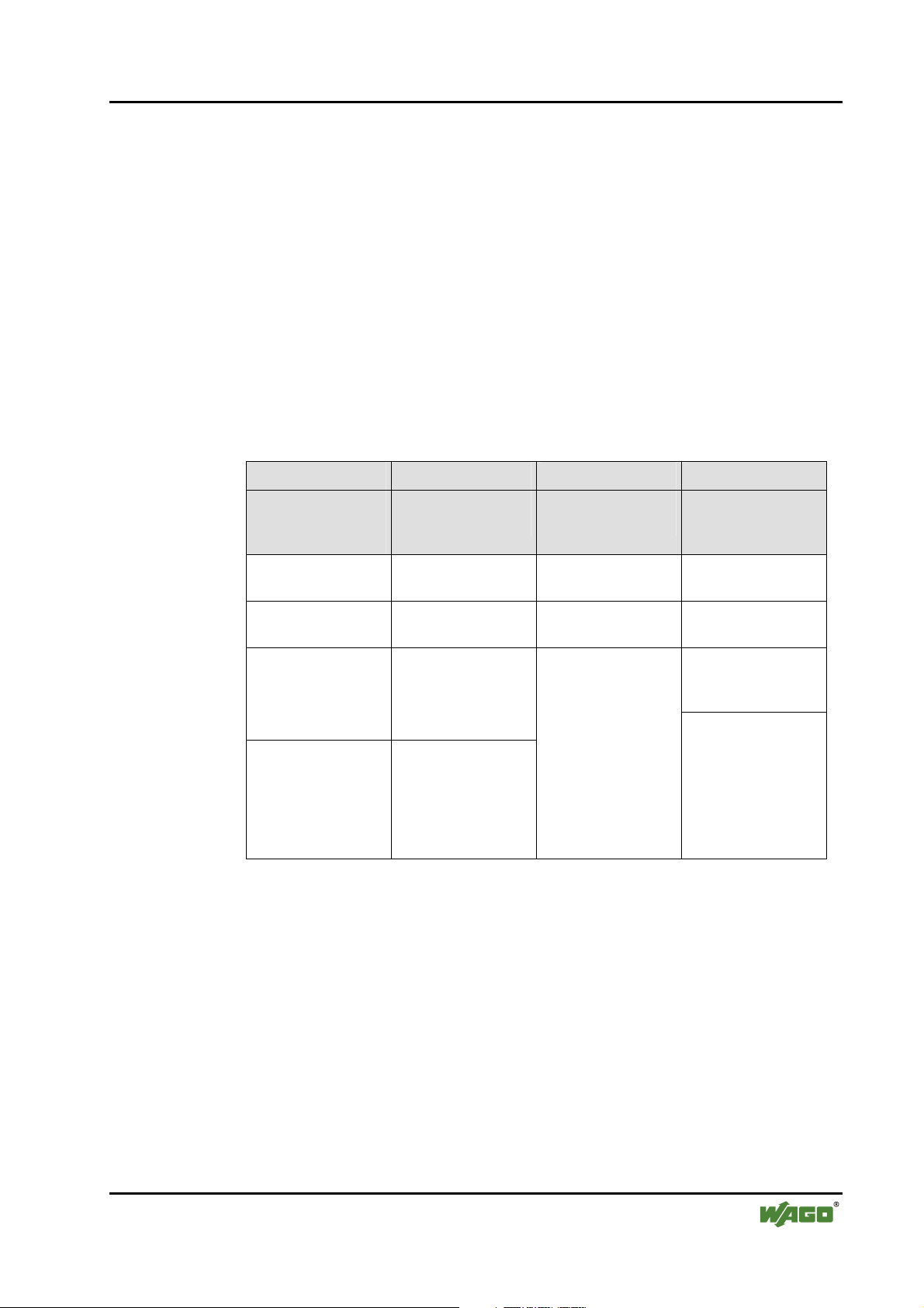
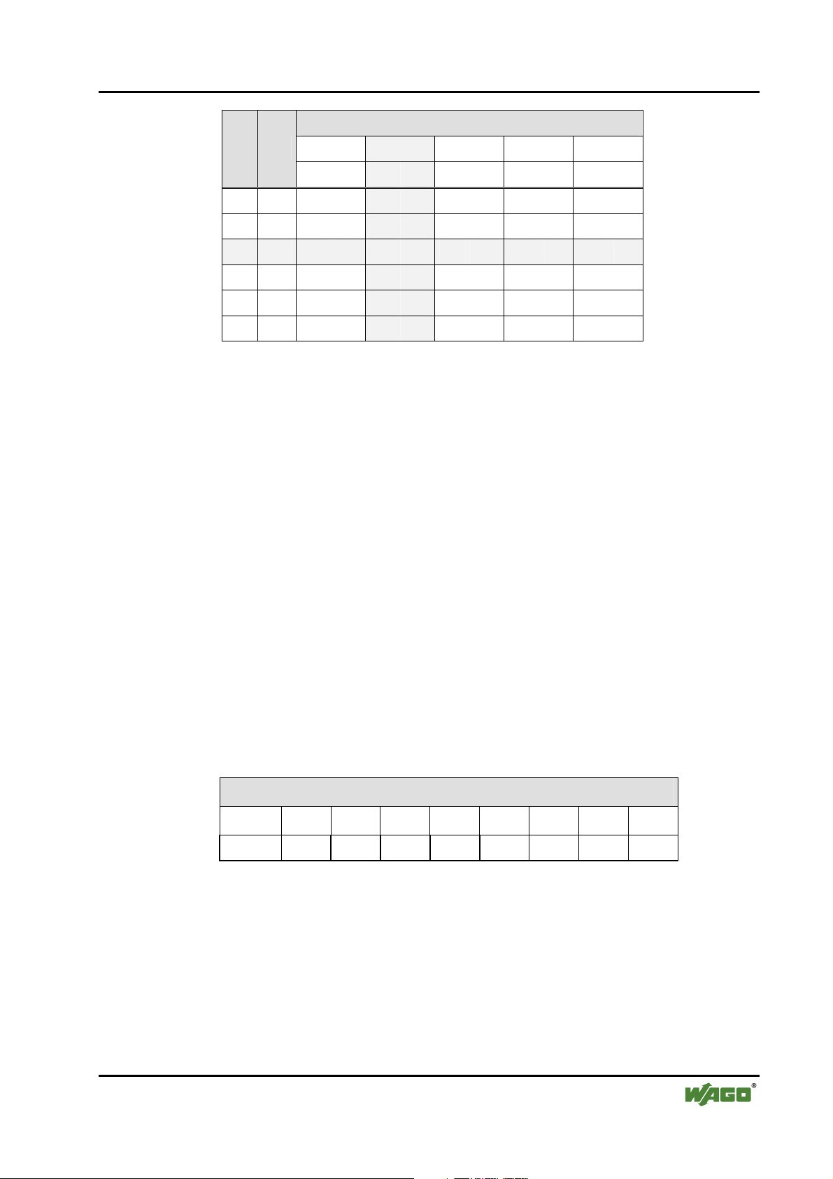
1.3 Number Notation
Number Code Example Note
Decimal 100 normal notation
Hexadecimal 0x64 C notation
Binary '100'
'0110.0100'
Within ',
Nibble separated with dots
WAGO-I/O-SYSTEM 750
I/O Modules
Page 8
8 • Important Comments
Safety Notes
1.4 Safety Notes
Warning
Switch off the system prior to working on bus modules!
In the event of deformed contacts, the module in question is to be replaced, as
its functionality can no longer be ensured on a long-term basis.
The components are not resistant against materials having seeping and
insulating properties. Belonging to this group of materials is: e.g. aerosols,
silicones, triglycerides (found in some hand creams).
If it cannot be ruled out that these materials appear in the component
environment, then additional measures are to be taken:
- installation of the components into an appropriate enclosure
- handling of the components only with clean tools and materials.
Attention
Cleaning of soiled contacts may only be done with ethyl alcohol and leather
cloths. Thereby, the ESD information is to be regarded.
1.5 Scope
Do not use any contact spray. The spray may impair the functioning of the
contact area.
The WAGO-I/O-SYSTEM 750 and its components are an open system. It
must only be assembled in housings, cabinets or in electrical operation
rooms. Access must only be given via a key or tool to authorized qualified
personnel.
The relevant valid and applicable standards and guidelines concerning the
installation of switch boxes are to be observed.
ESD (Electrostatic Discharge)
The modules are equipped with electronic components that may be destroyed
by electrostatic discharge. When handling the modules, ensure that the
environment (persons, workplace and packing) is well grounded. Avoid
touching conductive components, e.g. gold contacts.
This manual describes the Special Module 750-655
AS-Interface master module of the modular WAGO-I/O-SYSTEM 750.
Handling, assembly and start-up are described in the manual of the Fieldbus
Coupler. Therefore this documentation is valid only in the connection with the
appropriate manual.
WAGO-I/O-SYSTEM 750
I/O Modules
Page 9
750-655 [AS-Interface master module] • 9 View
2 I/O Modules
2.1 Special Modules
2.1.1 750-655 [AS-Interface master module]
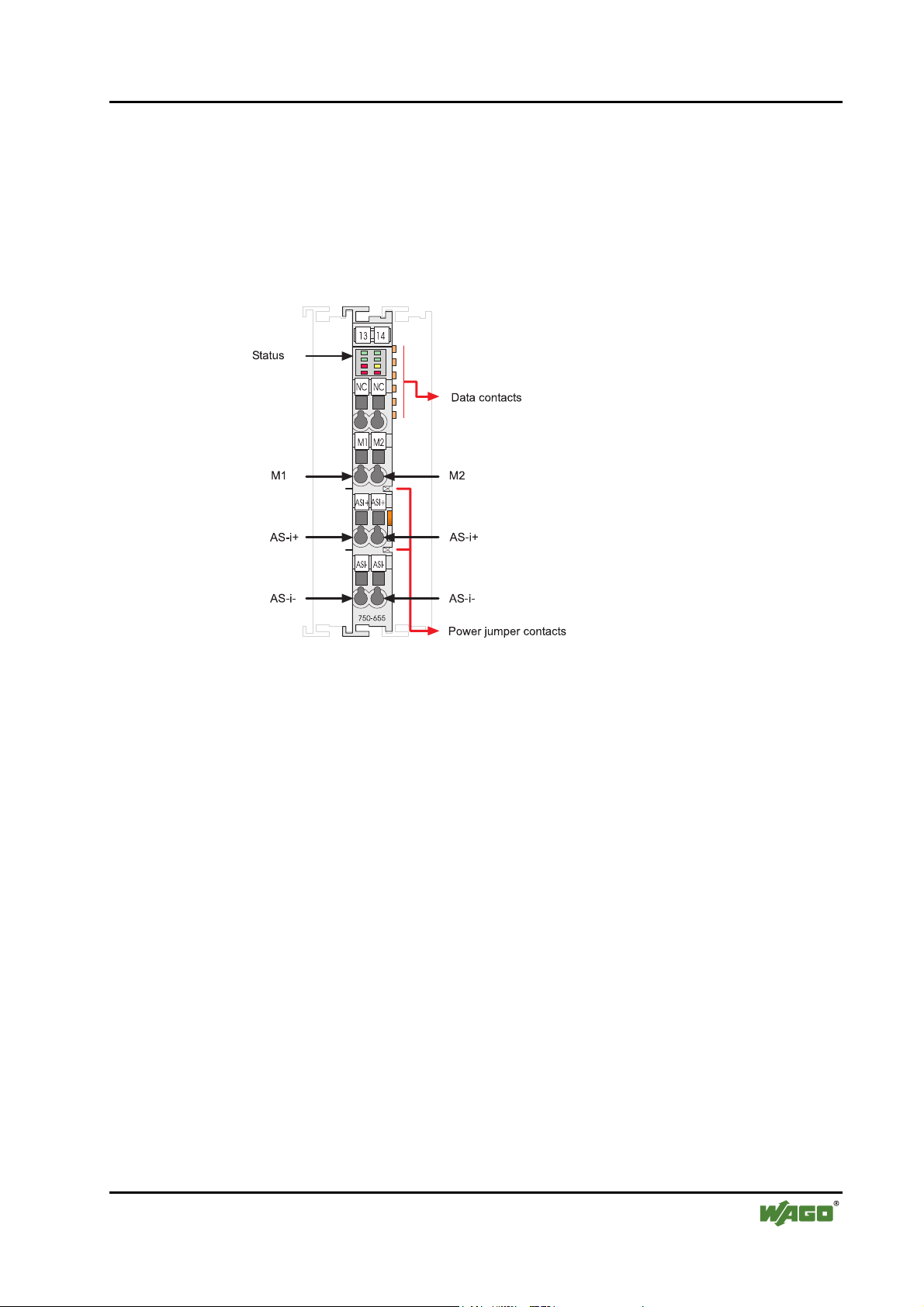
2.1.1.1 View
Fig. 2.1.1-1: View g065500e
2.1.1.2 Description
The AS-Interface master module 750-655 is used to integrate the AS-Interface
network into the WAGO-I/O-SYSTEM 750. By this means, AS-Interface
slaves or subsystems, together with modules from the WAGO-I/O-SYSTEM
750, can be used in widely differing field bus systems.
The AS-Interface master module 750-655 behaves as a master for the ASInterface and as a slave for the field bus.
It already complies with the new AS-Interface specification 2.1. This means
that:
• up to 62 AS-Interface slaves can be connected to the master,
• the transmission of analog values is integrated within the masters and
• all other functions of the new specification, such as the evaluation of
peripheral errors, are also implemented.
WAGO-I/O-SYSTEM 750
I/O Modules
Page 10
10 • 750-655 [AS-Interface master module]
Description
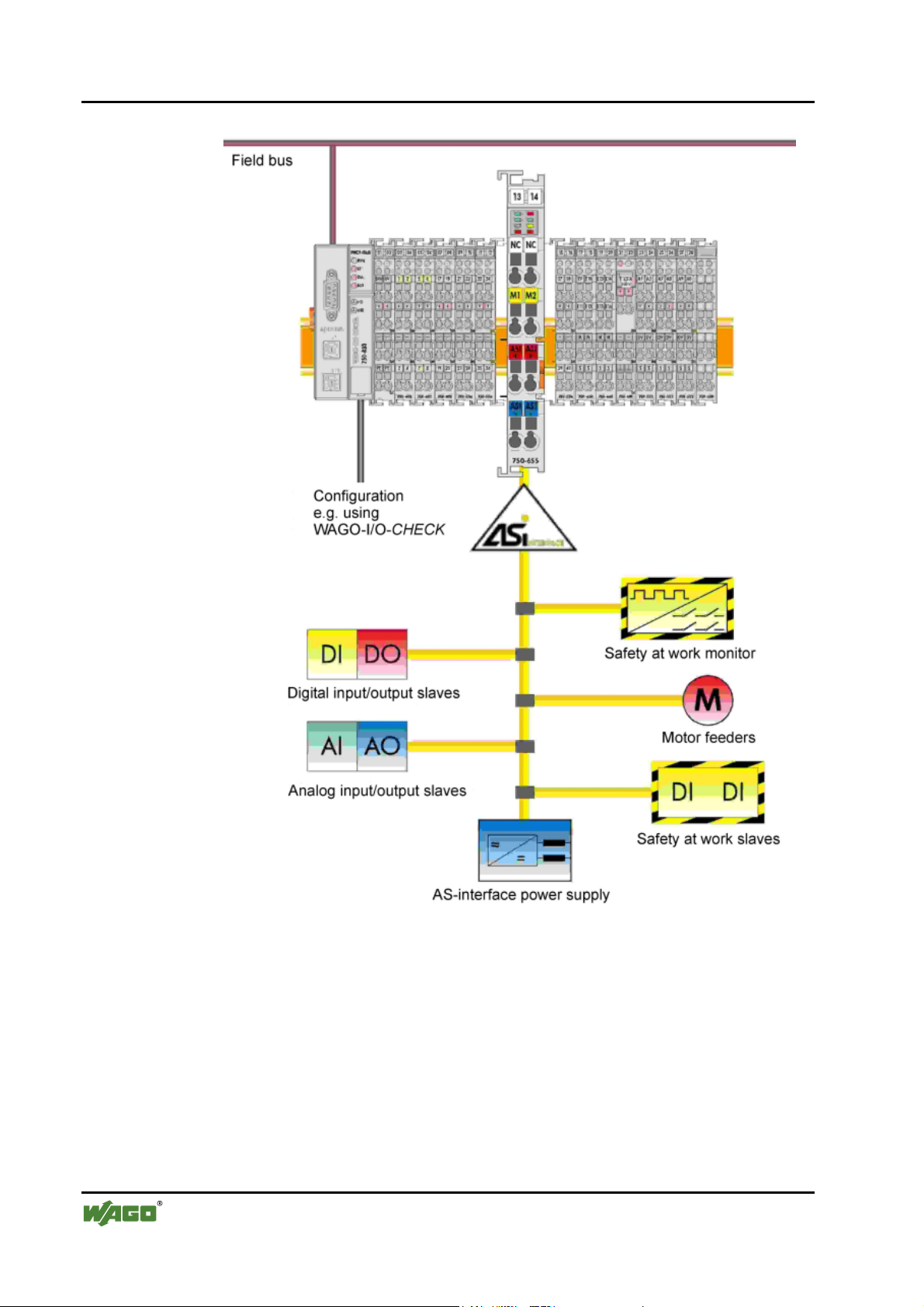
Fig. 2.1.1-2: Overview of the AS-Interface network p065501e
The AS-Interface functions are made available acyclically and the ASInterface process data are made available both cyclically and acyclically over
the field bus.
In cyclical data exchange, up to 32 bytes of I/O data (resettable) are
transmitted for the binary data of the AS-Interface strand.
In addition, analog values, and also all other commands of the new ASInterface specification, can be transmitted acyclically in a management
channel over the field bus.
WAGO-I/O-SYSTEM 750
I/O Modules
Page 11
750-655 [AS-Interface master module] • 11
Description
Diagnostics functions, which go well beyond the AS-Interface specification,
enable intermittent configuration errors and sources of interference on the ASInterface communication to be easily localized. In this way, the downtimes of
systems can be minimized in the case of a fault and preventative maintenance
measures can be implemented.
LEDs signal the readiness for operation and the fault-free module bus
communication as well as the status of the signal transmission.
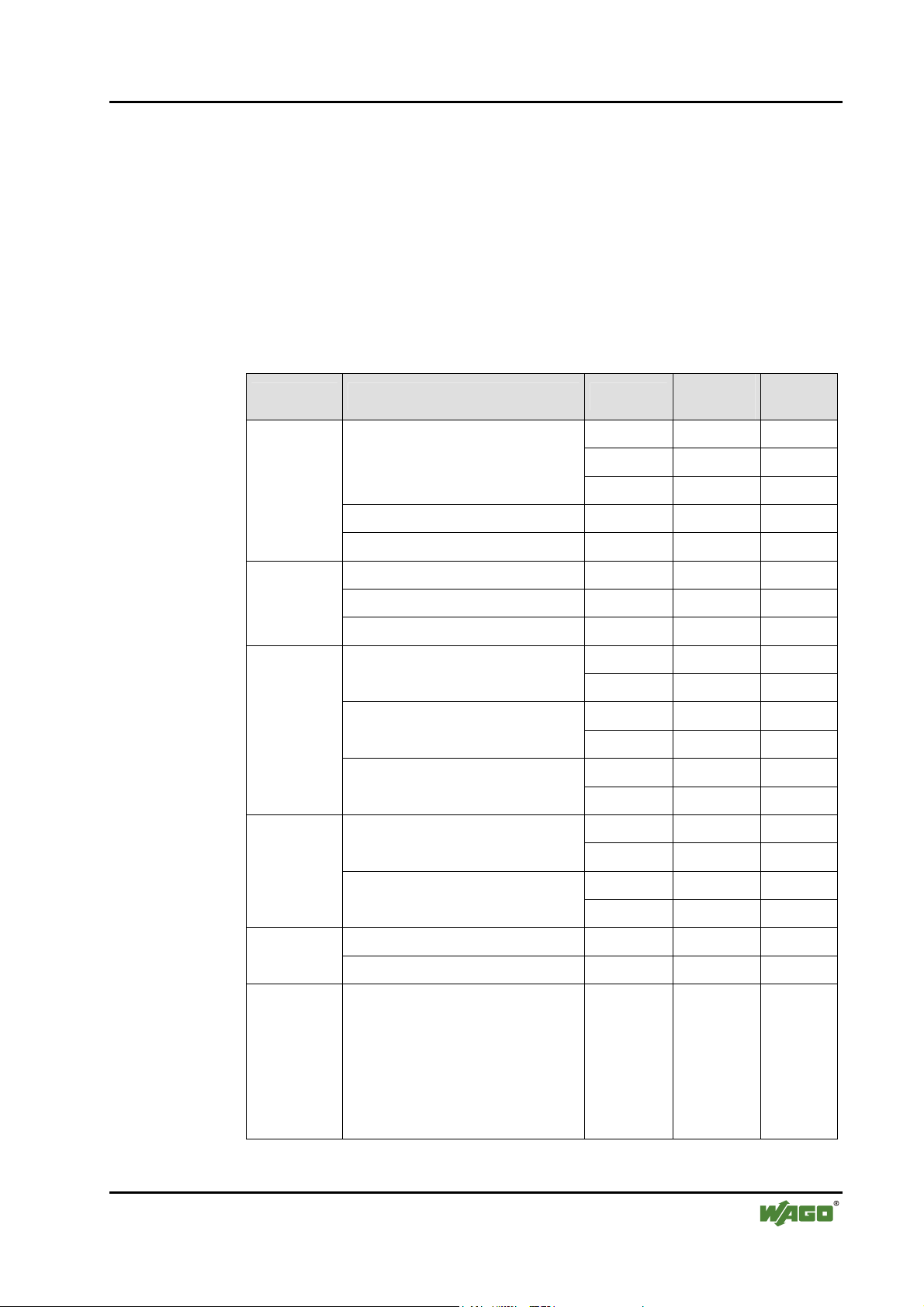
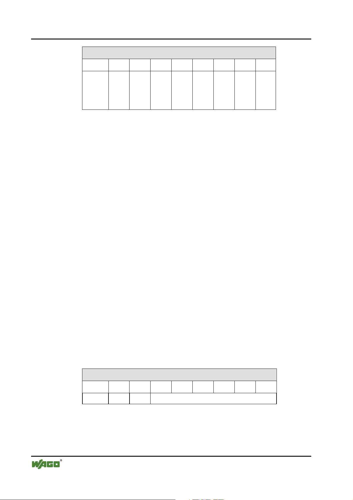
The AS-Interface master module 750-655 can be used with the following
WAGO-I/O-SYSTEM 750 couplers/controllers:
Bus system Coupler / Controller Item No.
Profibus
DeviceNet
CANopen
ETHERNET
Fieldbus coupler
ECO fieldbus coupler 750-343 03 from 06
Programmable fieldbus controller 750-833 12 from 07
Fieldbus coupler 750-306 11 4I
ECO fieldbus coupler 750-346 02 07
Programmable fieldbus controller 750-806 02 07
Programmable fieldbus controller
750-301 01 07
750-303 01 07
750-333 12 from 07
750-337 09 10 Fieldbus coupler
750-338 01 14
750-347 01 04 ECO fieldbus coupler
750-348 01 04
750-837 06 11
750-838 01 11
750-341 03 03 Fieldbus coupler
Hardware
version
Software
version
IPC WAGO-IPC 750-870 02 IPC-
Further couplers/controllers on request.
WAGO-I/O-SYSTEM 750
I/O Modules
750-342 04 14
Programmable fieldbus controller
Fieldbus coupler 750-319 07 05 LON
Programmable fieldbus controller 750-819 08 07
750-841 03 07
750-842 04 12
Firmware
02.04.
18/0200
KbusFirmware
01.02.
03(06)
Page 12

12 • 750-655 [AS-Interface master module]
Description
The version number is included in the fabrication number, which is printed on
the right-hand side of the bus module.
Note
A maximum of three AS-Interface master modules can be incorporated into
one fieldbus node. If it is intended to install two or three master modules in
direct vicinity to each other in one node, it is essential to observe the node
design acc. to chapter 2.1.2.1 „Grouping of AS-Interface Master Modules“.
WAGO-I/O-SYSTEM 750
I/O Modules
Page 13
750-655 [AS-Interface master module] • 13
Indicating devices
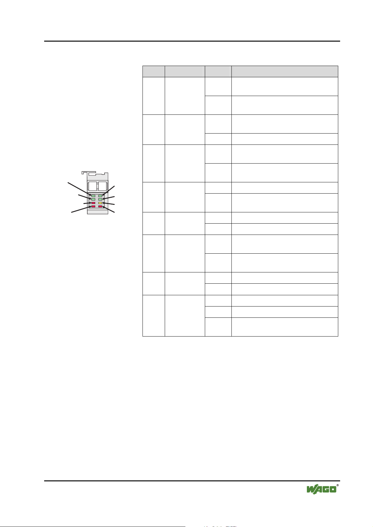
2.1.1.3 Indicating devices
LED Designation State Function
24 V - power
AS-interfacepower
Mapping
consistency
K-Bus timeout
overflow
Fig. 2.1.1-3: Indicating devices
13 14
AS-interface
active
prg enable
cfg mode
cfg error
g065502e
Power
green
AS-Interface
power
green
red
Mapping
consistency
Internal bus
timeout
red overflow
green
AS-Interface
active
green prg enable
off 24 V supply fault or
AS-Interface supply fault
on 24 V supply OK and
AS-Interface supply OK
off AS-Interface incomplete on internal bus
(mapping)
on AS-Interface complete on internal bus
off Communication to coupler/controller
OK
on Communication to coupler/controller
interrupted
off AS-Interface complete on internal bus
on AS-Interface incomplete on internal bus
(timing)
off AS-Interface not active
on AS-Interface active
off No automatic programming possible /
necessary
on A slave is missing and can be replaced
by automatic programming
yellow cfg mode
off Protected operating mode
on Set-up mode
off No fault
red general fault
flashing Peripheral fault
on Configuration error (Config Error Bit)
or at least one of the status bits 1 or 2
WAGO-I/O-SYSTEM 750
I/O Modules
Page 14
14 • 750-655 [AS-Interface master module]
Schematic circuit diagram
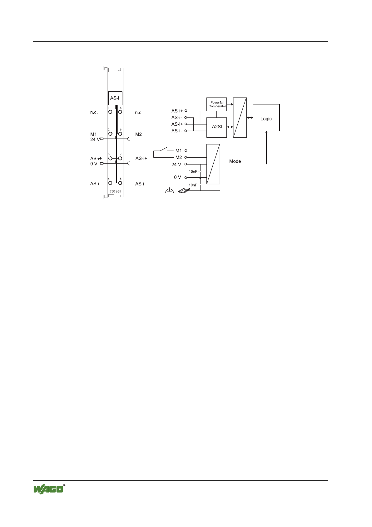
2.1.1.4 Schematic circuit diagram
Fig. 2.1.1-4: Schematic circuit diagram g065501e
WAGO-I/O-SYSTEM 750
I/O Modules
Page 15
750-655 [AS-Interface master module] • 15 Technical data
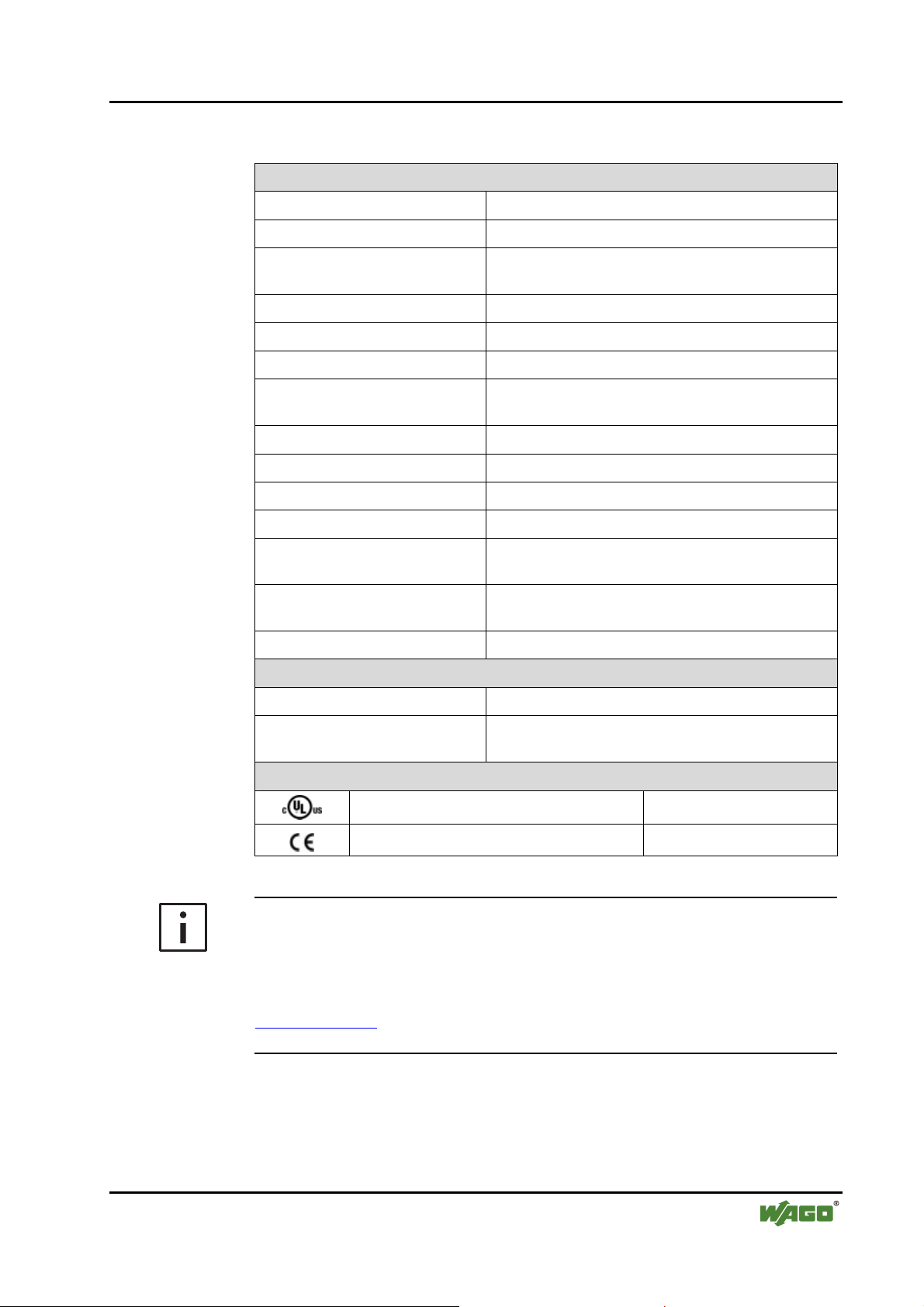
2.1.1.5 Technical data
Module-specific data
AS-Interface specification 2.1
Number of slaves up to 62
Current consumption (ASInterface)
Supply voltage (AS-Interface) 26.5 V ... 31.6 V
AS-Interface cable length max. 100 m, with repeater 300 m
Cycle time AS-Interface 0.3 ms ... 10 ms, depending on number of slaves
Configuration
Transmission channel 1
Current consumption max. (internal) 55 mA
Supply voltage DC 24 V via power contacts
Potential isolation 500 V system / supply / AS-Interface connection point
Data width 12 ... 48 bytes max. freely configurable,
Dimensions (mm) W x H x L 12 x 64* x 100
Weight ca. 70 g
Norms and Directives (cf. Chapter 2.2 in manual for coupler/controller)
EMC Immunity to interference CE according to EN 61000-6-2 (1996), EN 50295 (1999)
40 mA
via process image, WAGO-I/O-CHECK 2
or AS-Interface mode contacts
including 1 byte control / status
* from upper edge of mounting rail DIN 35
EMC Emissions of interference
CE
Approvals (cf. Chapter 2.2 in manual for coupler/controller)
(UL508)
CULUS
Conformity Marking
according to EN 61000-6-4 (2001)
More Information
Detailed references to the approvals are listed in the document "Overview
Approvals WAGO-I/O-SYSTEM 750", which you can find on the CD ROM
ELECTRONICC Tools and Docs (Item-No.: 0888-0412)
or in the internet under:
www.wago.com ! Documentation ! WAGO-I/O-SYSTEM 750 !
System Description
WAGO-I/O-SYSTEM 750
I/O Modules
Page 16
16 • 750-655 [AS-Interface master module]
Functional description
2.1.1.6 Functional description
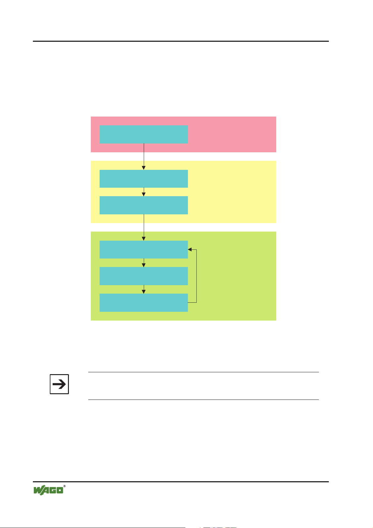
2.1.1.6.1 Start-up behavior
After switching on, all LEDs illuminate as part of a self test. Following this,
the LEDs indicate the status of the respective flags. On start-up, the ASInterface master module runs through the following phases:
Offline phase
Detection phase
Activation phase
Data exchange phase
Management phase
Acquisition phase
Initialisation
Start-up mode
Normal mode
Fig. 2.1.1-5: Start-up behavior g065503e
2.1.1.6.1.1 Offline phase
The master module is initialized; there is no exchange of data with the slaves.
Note
The master module will remain in the offline phase if the AS-Interface
circuit is not adequately supplied with power (U AS-I does not come on).
The offline phase can be exited in start-up mode or when the WAGO-I/O-
CHECK 2 commissioning tool starts automatically.
2.1.1.6.1.2 Detection phase
Beginning of start-up operation, in which a search is carried out for slaves
present on the AS-Interface. The master module remains in the detection
phase until at least one slave has been detected.
WAGO-I/O-SYSTEM 750
I/O Modules
Page 17
750-655 [AS-Interface master module] • 17
Functional description
2.1.1.6.1.3 Activation phase
State at the end of the start-up mode, in which the parameters of all the
connected and detected slaves are transmitted. At this point, access is enabled
to the data connections in the slaves.
Depending on the operating mode, either all detected and set-up slaves are
activated (protected mode of operation) or all detected slaves are activated
(set-up mode).
2.1.1.6.1.4 Normal mode
In the normal mode, the master module exchanges data with all active slaves
(data exchange phase), transmits management telegrams (telegrams from and
to the host, management phase) and searches for and activates newly
connected slaves (acquisition phase).
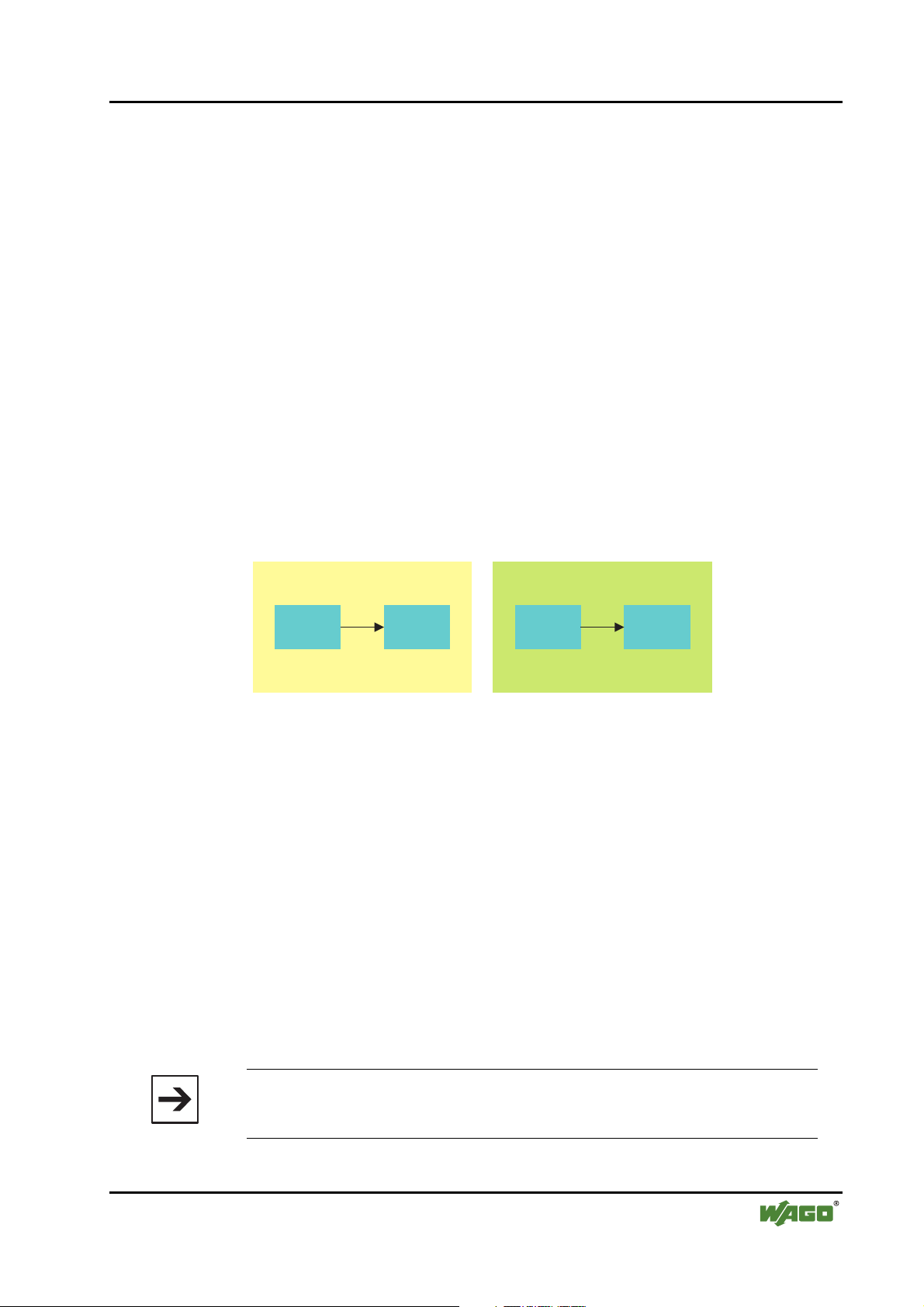
2.1.1.6.2 Slave lists
Information on available or set-up slaves is stored in the master in the form of
lists.
Set-up mode
LDS LAS
detected active projected active
Fig. 2.1.1-6: Slave lists g065504e
The list of detected slaves (LDS) includes all slaves, which the master detects
in the AS-Interface circuit and which have a valid address.
The list of projected slaves (LPS) includes all slaves, which the master expects
in the AS-Interface circuit as a result of the set-up.
The list of active slaves (LAS) includes all slaves with which the master
exchanges data. In the set-up mode, this list corresponds to the LDS list and,
in protected mode, it corresponds to the LPS list.
2.1.1.6.3 Operating modes
2.1.1.6.3.1 Set-up mode
Protected mode
LPS
LAS
The set-up mode is used for configuring the AS-Interface circuit.
Note
In the set-up mode, all detected slaves are activated even when there are
WAGO-I/O-SYSTEM 750
I/O Modules
differences between the required and actual configuration.
Page 18
18 • 750-655 [AS-Interface master module]
Functional description
The master module is switched to set-up mode by short-circuiting the mode
contacts M1 and M2 for at least five seconds. The yellow "prj mode" LED
illuminates in set-up mode. In set-up mode, all detected slaves, with the
exception of slave zero, are activated. The master module is in normal mode.
Data is exchanged between the master module and all detected slaves
regardless of whether the detected slaves have already been set up.
Note
The AS-Interface master module is supplied from the factory in set-up
mode.
2.1.1.6.3.2 Protected operating mode
The master module is switched from set-up mode to protected mode by shortcircuiting the mode contacts M1 and M2.
Brief short-circuit:
The master module switches from set-up mode to protected mode without
setting up the current actual configuration as a required configuration.
Short-circuiting for longer than five seconds:
The master module switches from set-up mode to protected mode. At the same
time, the actual configuration is stored in the module as a required
configuration.
Note
If a slave with the address zero is detected on the AS-Interface, it will not
be possible to exit the set-up mode.
Note
In protected mode, only those slaves are activated, which have been set up
and the required configuration of which matches the actual values.
Note
In contrast to the set-up mode, in protected mode, data is only exchanged
between the master module and the slaves that have been set-up.
WAGO-I/O-SYSTEM 750
I/O Modules
Page 19
750-655 [AS-Interface master module] • 19
Functional description
2.1.1.6.4 Addressing in set-up mode
AS-Interface systems on the master module can be commissioned with the
WAGO-I/O-CHECK 2 commissioning tool.
The procedure is described in Chapter Fehler! Verweisquelle konnte nicht
gefunden werden. "Fehler! Verweisquelle konnte nicht gefunden
werden.".
Commissioning can also be carried out using an addressing unit.
2.1.1.6.5 Addressing in the case of configuration errors
2.1.1.6.5.1 Automatic addressing
One of the great advantages of the AS-Interface is the automatic address
programming. If a slave fails due to a defect, it can be replaced by a physically
identical slave with the address zero. The master module detects this and
automatically addresses the new slave with the address of the defective slave.
The following requirements must be satisfied for automatic programming:
• The master module must be in protected mode.
• The enable flag "Auto_prog" must be set.
• Only one of the set-up slaves must be undetected.
• The new slave must have the same configuration data as the missing slave.
When these conditions are satisfied, the master module indicates this with the
"prg enable" LED. If a slave is then detected with the address zero, it will
automatically be reprogrammed with the address of the missing slave.
The "Auto_prog" flag for automatic programming can be switched on and off
with the WAGO-I/O-CHECK 2 commissioning tool.
Note
Only slaves with the address zero can be re-addressed by the master
module.
Note
Automatic address programming is not carried out if the two slaves have
different configuration data, i.e. are not physically identical from the ASInterface side.
WAGO-I/O-SYSTEM 750
I/O Modules
Page 20

20 • 750-655 [AS-Interface master module]
Functional description
2.1.1.6.5.2 Manual addressing
If several slaves have failed, the addresses of the new slaves must be set
manually. This can be carried out with the WAGO-I/O-CHECK 2
commissioning tool or an addressing unit.
Note
If several slaves fail, they can no longer be automatically replaced by the
master.
WAGO-I/O-SYSTEM 750
I/O Modules
Page 21
750-655 [AS-Interface master module] • 21 Process image
2.1.1.7 Process image
2.1.1.7.1 Overview
The length of the process image of the AS-Interface master module can be set
to fixed sizes of 12, 20, 24, 32, 40 or 48 bytes.
It consists of a control or status byte, a mailbox with a size of 0, 6, 10, 12 or
18 bytes and the AS-Interface process data, which can range from 0 to 32
bytes (Mode 1).
Alternatively, the mailbox can be set up to overlap, i.e. the mailbox is
temporarily superimposed on the AS-Interface process data with a length of 6,
10, 12 or 18 bytes depending on the total length of the process image that has
been configured (Mode 2).
Register communication is used to set up the module via the parameter
channel (Mode 3).
Mode 1 Mode 2.1 Mode 2.2 Mode 3
permanently
configured mailbox
(normal mode)
Control/Status
(1 byte, byte 0)
Internal use
(1 byte, byte 1)
Mailbox
(acyclical data,
0-18 bytes long,
bytes 2 to n)
Process data
(cyclical data,
0-32 bytes long,
bytes n+1 to m)
overlapping mailbox
activated
Control/Status
(1 byte, byte 0)
Internal use
(1 byte, byte 1)
Mailbox
(acyclical data,
6-18 bytes long,
bytes 2 to n)
Process data
(cyclical data,
0-32 bytes long,
bytes n+1 to m)
(take validity of data
into account!)
overlapping mailbox
deactivated
Control/Status
(1 byte, byte 0)
Internal use
(1 byte, byte 1)
Process data
(cyclical data,
0-32 bytes long,
bytes 2 to m)
register
communication
Control/Status
(1 byte, byte 0)
Internal use
(1 byte, byte 1)
Register data
(2 bytes, bytes 2 to
3)
Invalid data
(bytes 4 to m)
Changing between Mode 1 (permanently configured mailbox) and Mode 2
(overlapping mailbox) as well as the setting up of the mailbox and process
image sizes is carried out with the WAGO-I/O-CHECK 2 commissioning
tool or by means of the parameter channel via address 0. The values set are
mirrored in Register 33.
Mode 3 (register communication) is switched on and off with bit 27 of the
control byte. As this mode has a superimposed function, the previously
activated Mode 1 or 2 remains active after switching off.
All possible settings relating to the total process image length and mailbox
length are listed in the following tables.
WAGO-I/O-SYSTEM 750
I/O Modules
Page 22
22 • 750-655 [AS-Interface master module]
Process image
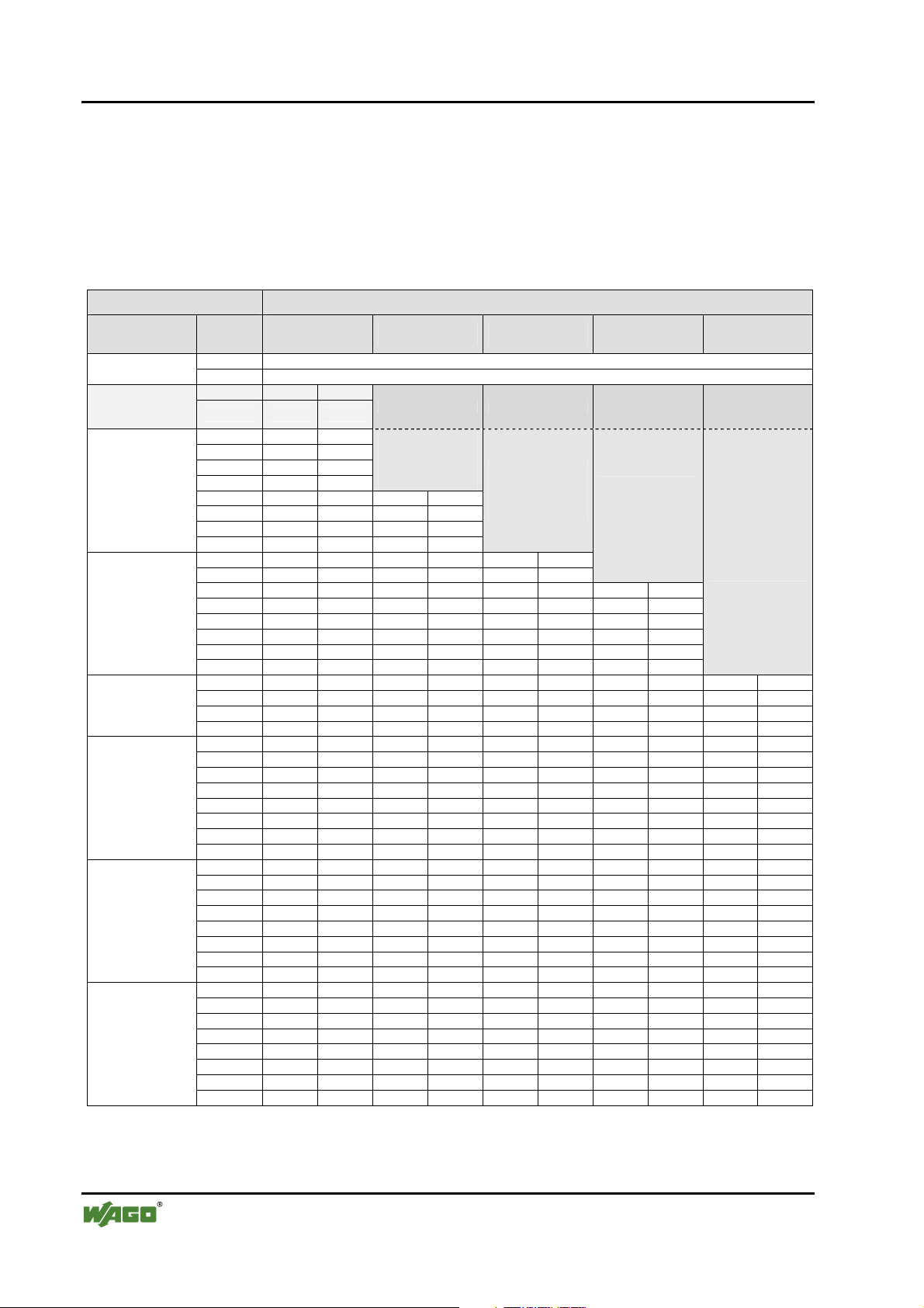
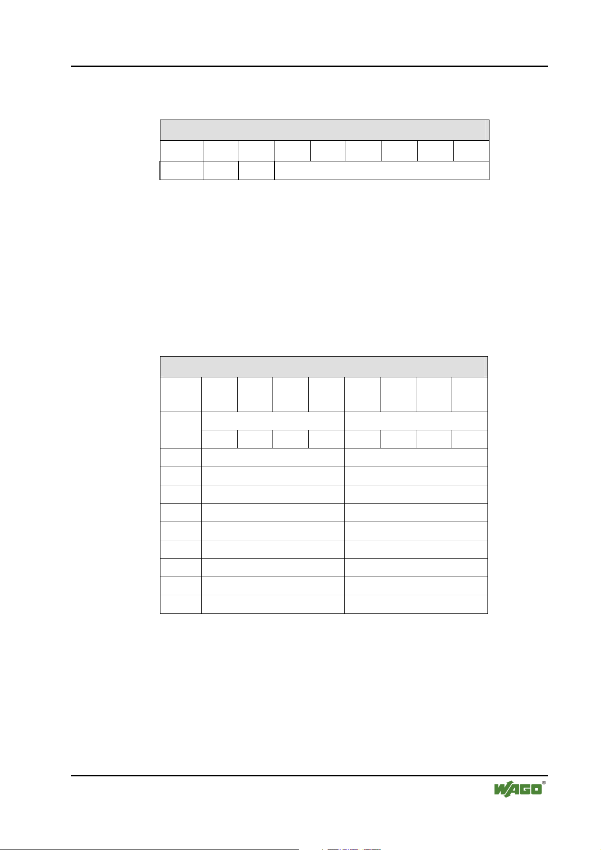
In Mode 1, the control/status byte, the mailbox and the cyclical process data
are mapped. This is the default setting.
When the difference between the process image length and the mailbox length
is less than 34 bytes, only the first part of the AS-Interface process data is
transmitted; the data for the slaves with the higher addresses are then omitted.
Mode 1 Mailbox length (permanently configured)
Process image
length
in control byte =
TRUE)
12 byte
20 byte
24 byte
32 byte
40 byte
48 byte
PI offset
in bytes
0 Control or status byte
1 Internal use
2 Flags 1/1A Register data (bit 27
3 2/2A 3/3A
4 4/4A 5/5A
5 6/6A 7/7A
6 8/8A 9/9A
7 10/10A 11/11A
8 12/12A 13/13A Flags 1/1A
9 14/14A 15/15A 2/2A 3/3A
10 16/16A 17/17A 4/4A 5/5A
11 18/18A 19/19A 6/6A 7/7A
12 20/20A 21/21A 8/8A 9/9A Flags 1/1A
13 22/22A 23/23A 10/10A 11/11A 2/2A 3/3A
14 24/24A 25/25A 12/12A 13/13A 4/4A 5/5A Flags 1/1A
15 26/26A 27/27A 14/14A 15/15A 6/6A 7/7A 2/2A 3/3A
16 28/28A 29/29A 16/16A 17/17A 8/8A 9/9A 4/4A 5/5A
17 30/30A 31/31A 18/18A 19/19A 10/10A 11/11A 6/6A 7/7A
18 Flags 1B 20/20A 21/21A 12/12A 13/13A 8/8A 9/9A
19 2B 3B 22/22A 23/23A 14/14A 15/15A 10/10A 11/11A
20 4B 5B 24/24A 25/25A 16/16A 17/17A 12/12A 13/13A Flags 1/1A
21 6B 7B 26/26A 27/27A 18/18A 19/19A 14/14A 15/15A 2/2A 3/3A
22 8B 9B 28/28A 29/29A 20/20A 21/21A 16/16A 17/17A 4/4A 5/5A
23 10B 11B 30/30A 31/31A 22/22A 23/23A 18/18A 19/19A 6/6A 7/7A
24 12B 13B Flags 1B 24/24A 25/25A 20/20A 21/21A 8/8A 9/9A
25 14B 15B 2B 3B 26/26A 27/27A 22/22A 23/23A 10/10A 11/11A
26 16B 17B 4B 5B 28/28A 29/29A 24/24A 25/25A 12/12A 13/13A
27 18B 19B 6B 7B 30/30A 31/31A 26/26A 27/27A 14/14A 15/15A
28 20B 21B 8B 9B Flags 1B 28/28A 29/29A 16/16A 17/17A
29 22B 23B 10B 11B 2B 3B 30/30A 31/31A 18/18A 19/19A
30 24B 25B 12B 13B 4B 5B Flags 1B 20/20A 21/21A
31 26B 27B 14B 15B 6B 7B 2B 3B 22/22A 23/23A
32 28B 29B 16B 17B 8B 9B 4B 5B 24/24A 25/25A
33 30B 31B 18B 19B 10B 11B 6B 7B 26/26A 27/27A
34 - - 20B 21B 12B 13B 8B 9B 28/28A 29/29A
35 - - 22B 23B 14B 15B 10B 11B 30/30A 31/31A
36 - - 24B 25B 16B 17B 12B 13B Flags 1B
37 - - 26B 27B 18B 19B 14B 15B 2B 3B
38 - - 28B 29B 20B 21B 16B 17B 4B 5B
39 - - 30B 31B 22B 23B 18B 19B 6B 7B
40 - - - - 24B 25B 20B 21B 8B 9B
41 - - - - 26B 27B 22B 23B 10B 11B
42 - - - - 28B 29B 24B 25B 12B 13B
43 - - - - 30B 31B 26B 27B 14B 15B
44 - - - - - - 28B 29B 16B 17B
45 - - - - - - 30B 31B 18B 19B
46 - - - - - - - - 20B 21B
47 - - - - - - - - 22B 23B
0 byte 6 byte 10 byte 12 byte 18 byte
Mailbox
Mailbox
Mailbox
Mailbox
WAGO-I/O-SYSTEM 750
I/O Modules
Page 23
750-655 [AS-Interface master module] • 23
Process image
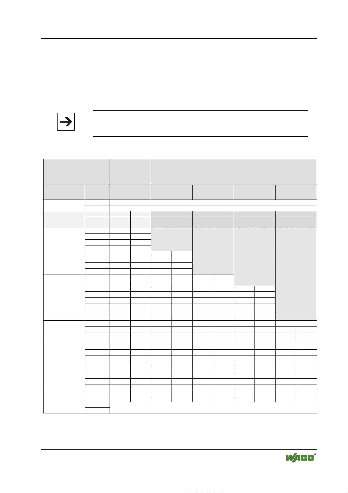
Mode 2 describes the operating mode with suppressible mailbox.
If the mailbox flag (bit 25 in the control byte) is set, then the mailbox is
imposed over the cyclical data range. The covered range is then no longer
valid (the range not covered continues to be updated, however, and can
therefore be used). If the mailbox flag is not set, then the mailbox is
suppressed and the cyclical data range becomes valid. The required setting is
acknowledged by mirroring in bit 25 of the status byte.
Note
The application program must take into account the validity of the data
ranges.
Mailbox
Mode 2
Process image
length
in control byte =
TRUE)
12 byte
20 byte
24 byte
32 byte
40 byte
suppressed (bit 25
in control byte =
FALSE)
PI offset
in bytes
0 Control or status byte
1 Internal use
2 Flags 1/1A Register data (bit 27
3 2/2A 3/3A
4 4/4A 5/5A
5 6/6A 7/7A
6 8/8A 9/9A
7 10/10A 11/11A
8 12/12A 13/13A 12/12A 13/13A
9 14/14A 15/15A 14/14A 15/15A
10 16/16A 17/17A 16/16A 17/17A
11 18/18A 19/19A 18/18A 19/19A
12 20/20A 21/21A 20/20A 21/21A 20/20A 21/21A
13 22/22A 23/23A 22/22A 23/23A 22/22A 23/23A
14 24/24A 25/25A 24/24A 25/25A 24/24A 25/25A 24/24A 25/25A
15 26/26A 27/27A 26/26A 27/27A 26/26A 27/27A 26/26A 27/27A
16 28/28A 29/29A 28/28A 29/29A 28/28A 29/29A 28/28A 29/29A
17 30/30A 31/31A 30/30A 31/31A 30/30A 31/31A 30/30A 31/31A
18 Flags 1B Flags 1B Flags 1B Flags 1B
19 2B 3B 2B 3B 2B 3B 2B 3B
20 4B 5B 4B 5B 4B 5B 4B 5B 4B 5B
21 6B 7B 6B 7B 6B 7B 6B 7B 6B 7B
22 8B 9B 8B 9B 8B 9B 8B 9B 8B 9B
23 10B 11B 10B 11B 10B 11B 10B 11B 10B 11B
24 12B 13B 12B 13B 12B 13B 12B 13B 12B 13B
25 14B 15B 14B 15B 14B 15B 14B 15B 14B 15B
26 16B 17B 16B 17B 16B 17B 16B 17B 16B 17B
27 18B 19B 18B 19B 18B 19B 18B 19B 18B 19B
28 20B 21B 20B 21B 20B 21B 20B 21B 20B 21B
29 22B 23B 22B 23B 22B 23B 22B 23B 22B 23B
30 24B 25B 24B 25B 24B 25B 24B 25B 24B 25B
31 26B 27B 26B 27B 26B 27B 26B 27B 26B 27B
32 28B 29B 28B 29B 28B 29B 28B 29B 28B 29B
33 30B 31B 30B 31B 30B 31B 30B 31B 30B 31B
...
39
n byte mailbox 6 byte mailbox 10 byte mailbox 12 byte mailbox 18 byte mailbox
Empty
Mailbox imposed
(bit 25 in control byte = TRUE)
Mailbox
Mailbox
Mailbox
Mailbox
WAGO-I/O-SYSTEM 750
I/O Modules
Page 24
24 • 750-655 [AS-Interface master module]
Process image
Mode 3 is reserved for register communication. Bit 27 in the control byte is set
to activate register communication. Resetting this bit switches register
communication off again. The selected setting is mirrored in bit 27 of the
status byte. The register data are superimposed on the PI offset byte 2 and byte
3 over the respective cyclical or acyclical memory range depending on the
selected mode.
Note
In Mode 3, the mailbox and the process data are basically no longer valid.
Process image length and mailbox length:
The process image length and the mailbox length can be freely set within fixed
limits with the limitation that the process image length is greater than the
mailbox length plus two control/status bytes.
The size of the process image can be set to 12 bytes, 20 bytes, 24 bytes, 32
bytes, 40 bytes or 48 bytes.
The mailbox length can be set to 0 bytes, 6 bytes, 10 bytes, 12 bytes or 18
bytes.
Note
If a mailbox length of 0 bytes is set, it will only be possible to access the
process data of digital slaves.
AS-Interface process data:
The length of the AS-Interface data and thus the number of transferable slaves
is given by the combination of the above-mentioned process image and
mailbox settings.
AS-Interface process data length = (Process image length – Mailbox length – 2)
The following table shows a summary of the permissible configurations of
process image and mailbox:
WAGO-I/O-SYSTEM 750
I/O Modules
Page 25
750-655 [AS-Interface master module] • 25
Process image
Mailbox length
PI C/S
12 2 10 19 4 7 0 0 - - - -
20 2 18 34 12 23 8 15 6 11 0 0
24 2
32 2 30 58 24 46 20 38 18 34 12 23
40 2 38 62 32 62 28 54 26 50 18 38
48 2 46 62 40 62 36 62 34 62 28 54
PI Length of process image that can be set
C/S Number of status and control bytes (incl. filler bytes)
PD Length of AS-Interface process data
SL Number of transferable slaves
0 byte 6 byte 10 byte 12 byte 18 byte
PD SL PD SL PD SL PD SL PD SL
22 42
16 31
12 23 10 19 4 7
The standard setting is a process image length of 24 bytes and a mailbox
length of 6 bytes. This results in an AS-Interface process data length of 16
bytes, i.e. 31 slaves can be read out.
2.1.1.7.2 Control and status byte
The bus master switches between process data communication and register
communication with bit 27 in the control byte.
The changeover is acknowledged by the bus module with bit 27 in the status
byte.
2.1.1.7.2.1 Assignment for process data communication
With process data communication, the control and status bytes are assigned as
follows:
Control byte
Byte 27 26 25 24 23 22 21 20
1 0 0 mbx 0 0 0 0 0
0 Mailbox suppressed mbx
1 Mailbox superimposed
The superimposition of the mailbox is activated and deactivated with bit 25 in
the control byte.
With process data communication, bit 27 in the control byte is always reset.
WAGO-I/O-SYSTEM 750
I/O Modules
Page 26
26 • 750-655 [AS-Interface master module]
Process image
Status byte
Byte 27 26 25 24 23 22 21 20
1 0 gen.
fault
0 AS-Interface complete on internal bus Overflow
1 AS-Interface incomplete on internal bus (timing)
0 AS-Interface active AS-I
1 AS-Interface not active
0 AS-Interface supply OK and 24 V supply OK AS-Interface
power
consistency
(config error)
1 AS-Interface supply fault or 24 V supply fault
0 AS-Interface complete on internal bus Mapping
1 AS-Interface incomplete on internal bus (mapping)
0 Protected operating mode cnf mode
1 Set-up mode
0 Mailbox suppressed mbx
1 Mailbox superimposed
0 No fault General fault
1 Configuration error or at least one of the status bits 1 or 2
mbx cnf
mode
Map-
ping
consist-
ency
AS-
inter-
face -
power
AS-I Over-
flow
The status of the AS-Interface master module is indicated by the bits 20 to 24
and 26 in the status byte.
The superimposition of the mailbox is acknowledged by the bus module with
5
in the status byte.
bit 2
Process data communication is acknowledged by the bus module with bit 2
the status byte.
2.1.1.7.2.2 Assignment for register communication
With register communication, the control and status bytes are assigned as
follows:
Control byte
Byte 27 26 25 24 23 22 21 20
1 1 R/W Register number
0 Read access R/W
1 Write access
7
in
WAGO-I/O-SYSTEM 750
I/O Modules
Page 27
750-655 [AS-Interface master module] • 27
Process image
Bit 26 (R/W) in the control byte determines the register read or write access.
With register communication, bit 27 in the control byte is always set.
Status byte
Byte 27 26 25 24 23 22 21 20
1 1 — Register number
Register communication is acknowledged by the bus module with bit 27 in the
status byte.
2.1.1.7.3 AS-Interface process data
In the data field of the AS-Interface process data, the data for (or from) 2
slaves are transmitted with each byte. In doing so, the data for the slave with
the higher address are located in the lower value nibble.
The main EC (Execution Control) flags or control bits are transmitted in place
of slave 0, with which the master does not exchange any process data.
AS-Interface process data
Byte
offset
0
1 Slave 2/2A Slave 3/3A
… … …
14 Slave 28/28A Slave 29/29A
15 Slave 30/30A Slave 31/31A
16 Reserved Slave 1B
17 Slave 2B Slave 3B
… … …
30 Slave 28B Slave 29B
31 Slave 30B Slave 31B
27 26 25 24 23 22 21 20
Flags Slave 1/1A
F3 F2 F1 F0 D3 D2 D1 D0
Depending on the process image length, mailbox length and mailbox mode, it
may be that not all AS-Interface process data are transmitted (cf. Chapter
2.1.1.7.1 "Overview process image").
WAGO-I/O-SYSTEM 750
I/O Modules
Page 28

28 • 750-655 [AS-Interface master module]
Process image
2.1.1.7.3.1 AS-Interface flags
Flags
Input data Output data
F0 ConfigError Offline
F1 APF LOS master bit
F2 PeripheryFault A rising edge switches the
master to the set-up mode
F3 ConfigurationActive A rising edge switches the
master to the protected mode
0 Config OK ConfigError:
1 Config error
0 AS-Interface power OK APF:
1 AS-Interface power failed
0 Periphery OK PeripheryFault:
All bits in the LOS are set with a rising edge of the LOS master bit. All bits in
the LOS are reset with a falling edge of the LOS master bit.
2.1.1.7.4 Mailbox
As well as the 32 bytes of input and output data, an AS-Interface master
manages a large amount of configuration and parameter data. These data are
only required for setting up the AS-Interface circuit and for diagnostics and
therefore only have to be read or written occasionally.
In addition, the master supports slaves according to profile S-7.3 and S-7.4
and other multiplexing slaves, whereby large amounts of data can also occur.
1 Periphery fault
0 Configuration inactive, master in protected mode ConfigurationActive:
1 Configuration active, master in set-up mode
0 Online Offline:
1 Offline
0 Offline with ConfigError deactivated LOS master bit:
1 Offline with ConfigError activated
Access is made to these non-time-critical data via the mailbox.
WAGO-I/O-SYSTEM 750
I/O Modules
Page 29
750-655 [AS-Interface master module] • 29
Process image
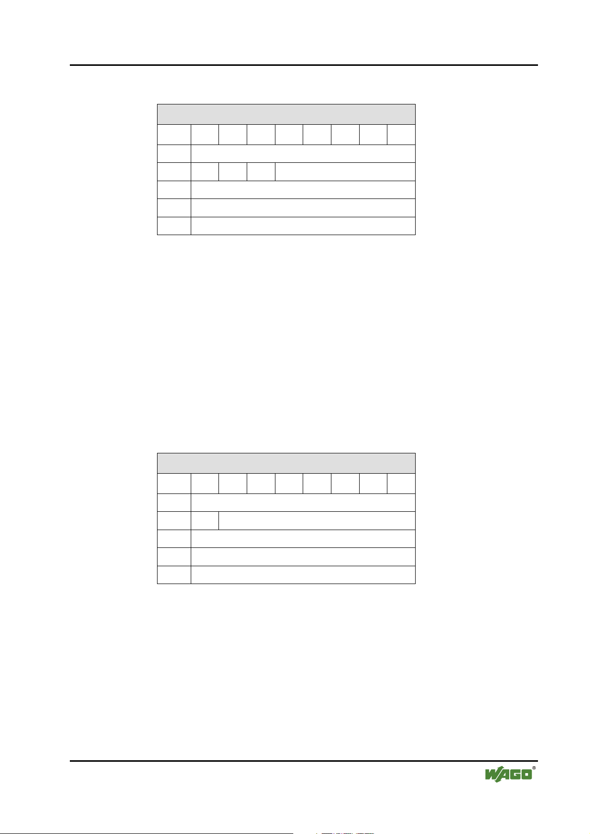
2.1.1.7.4.1 Structure
Mailbox request
Byte 27 26 25 24 23 22 21 20
1 Opcode
2 T O A/B -
3 Request parameter byte 1
… …
36 Request parameter byte 34
Opcode Command code for the mailbox order
T Toggle flag A mailbox order is started when a change occurs.
O Order flag
(for mailbox orders
with bit information)
A/B
(for 6-byte mailbox
orders with bit
information)
Channel changeover
(for 6-byte mailbox
orders with word
information)
0 Bits are stored in parameter bytes in ascending order
(default value).
1 Bits are stored in parameter bytes in descending order.
0 A-slave data are transmitted before B-slave data. Slave changeover
1 B-slave data are transmitted before A-slave data.
0 Analog values are transmitted in the order Channel 1,
Channel 2, Channel 3, Channel 4.
1 Analog values are transmitted in the order Channel 3,
Channel 4, Channel 1, Channel 2.
Mailbox response
Byte 27 26 25 24 23 22 21 20
1 Opcode (mirrored)
2 T Result
3 Response parameter byte 1
… …
34 Response parameter byte 32
Opcode Mirrored command code for the mailbox order
T Toggle flag A mailbox order is acknowledged when a change occurs.
Result Status / error in the mailbox order
In most cases, the mailbox will not have the full length in order to provide
space for the AS-Interface process data.
WAGO-I/O-SYSTEM 750
I/O Modules
Page 30

30 • 750-655 [AS-Interface master module]
Process image
2.1.1.7.4.2 Access procedure
The user first writes the request parameter and then the opcode and toggle
flag. As soon as the opcode or toggle flag changes, the master interprets the
mailbox range of the module bus output data as a complete mailbox command
and executes it. In doing so, the response parameters are stored in the mailbox
range of the internal bus input data.
When the command has been processed, the master mirrors the opcode and the
toggle flag. From this, the user recognizes that his request has been dealt with
and the result is available in the internal bus input data.
The toggle flag is required so that two mailbox commands with the same
opcode (but possibly different parameters) can be executed directly after one
another.
The execution of a mailbox command is declined if the number of request
parameter bytes transmitted (in the output data direction) is too small, i.e. if
the mailbox length has been set too low.
WAGO-I/O-SYSTEM 750
I/O Modules
Page 31

750-655 [AS-Interface master module] • 31
Mailbox commands
2.1.1.8 Mailbox commands
2.1.1.8.1 Overview of mailbox commands
Opcode
IDLE 0x00 No order 2 2 ● ● ● ● 73
Configuration
GET_LDS_A/B 0x46 Get_List_of_Detected_Slaves 2 10 A/B ● ● ● 89
READ_CDI 0x28 Read_Actual_Configuration 3 4 ● ● ● ● 82
STORE_CDI 0x07 Store_Actual_Configuration 2 2 ● ● ● ● 81
SET_PCD 0x25 Set_Permanent_Configuration 5 2 ● ● ● ● 79
GET_PCD 0x26 Get_Permanent_Configuration 3 4 ● ● ● ● 80
GET_LPS_A/B 0x44 Get_List_of_Projected_Slaves 2 10 A/B ● ● ● 85
SET_LPS_A/B 0x6B Set_List_of_Projected_Slaves 10 2 A/B ● ● ● 83
GET_LAS_A/B 0x45 Get_List_of_Activated_Slaves 2 10 A/B ● ● ● 87
Parameters
GET_PP 0x01 Get_Permanent_Parameter 3 3 ● ● ● ● 75
SET_PP 0x43 Set_Permanent_Parameter 4 2 ● ● ● ● 74
READ_PI 0x03 Read_Parameter_from_Image 3 3 ● ● ● ● 77
Valu
e
Meaning
Req
Len
Executable with
Res
mailbox
Len
Page
6 10 12 18
WRITE_P 0x02 Write_Parameter 4 3 ● ● ● ● 76
STORE_PI 0x04 Store_Actual_Parameter_Image 2 2 ● ● ● ● 78
GET_DELTA_A/B*) 0x57 Get list of config. diff. 2 10 A/B ● ● ● 110
SLAVE_ADDR 0x0D Change_Slave_Address 4 2 ● ● ● ● 96
Diagnosis
GET_FLAGS 0x47 Get_Flags 2 5 ● ● ● ● 91
GET_LPF_A/B 0x3E Get_List_of_Peripheral_Failure 2 10 A/B ● ● ● 99
GET_LCS_A/B*) 0x6C Get_List_of_Corrupted_Slaves 2 10 A/B ● ● ● 116
GET_TEC_X*) 0x66 Get transm.err.counters X-Slaves 4
Operation Modes
SET_OP_MODE 0x0C Set_Operation_Mode 3 2 ● ● ● ● 93
SET_OFFLINE 0x0A Set_Off-Line_Mode 3 2 ● ● ● ● 94
SET_DATA_EX 0x48 Set_Data_Exchange_Active 3 2 ● ● ● ● 95
SET_AAE 0x0B Set_Auto_Adress_Enable 3 2 ● ● ● ● 97
GET_LOS_A/B*) 0x61 GET_LOS 2 10 A/B ● ● ● 118
SET_LOS_A/B*) 0x6D SET_LOS 10 2 A/B ● ● ● 120
≥5
● ● ● ● 122
Special Functions
WRITE_XID1 0x3F Write_Extended_ID-Code_1 3 2 ● ● ● ● 101
WAGO-I/O-SYSTEM 750
I/O Modules
Page 32

32 • 750-655 [AS-Interface master module]
Mailbox commands
Opcode
EXEC_CMD 0x49 Execute_Command 4 3 ● ● ● ● 98
FP_PARAM*) 0x7D „Functional Profile“ Param.
FP_DATA*) 0x7E „Functional Profile“ Data
Digital Slaves
RD_SLV_DATA*) 0x5E Read_Slave_Data 3 6 ● ● ● ● 102
WR_SLV_DATA*) 0x5F Write_Slave_Data 4 2 ● ● ● ● 103
16 Bit Slaves
RD_7X_IN_A/B 0x50 Read 1 7.3-slave in.data 3 10 A/B ● ● ● 104
WR_16BIT_OUT_S 0x6F WR_16BIT_OUT_S 6 2 ● ● ● ● 107
WR_7X_OUT 0x51 Write 1 7.3-slave out.data 11 2 - - ● ● 106
RD_7X_OUT_A/B 0x52 Read 1 7.3-slave out.data 3 10 A/B ● ● ● 108
Extended 16 Bit Slaves
WR_74_PARAM 0x5A Write S-7.4-slave parameter
RD_74_PARAM 0x5B Read S-7.4-slave parameter 4
Valu
e
Meaning
Req
Len
≥3 ≥2
≥3 ≥2
≥6
Executable with
Res
mailbox
Len
6 10 12 18
● ● ● ● 124
● ● ● ● 125
2 ● ● ● ● 112
● ● ● ● 113
≥3
Page
RD_74_ID 0x5C Read S-7.4-slave ID string 4
RD_74_DIAG 0x5D Read S-7.4-slave diagnosis string 4
Housekeeping
BUTTONS*) 0x75 Disable Pushbuttons 3 2 ● ● ● ● 123
*) Command in addition to AS-Interface specification
● Command is executable
- Command is not executable
A/B Command is executable with changeover between A/B slaves or channels
● ● ● ● 114
≥3
● ● ● ● 115
≥3
WAGO-I/O-SYSTEM 750
I/O Modules
Page 33

750-655 [AS-Interface master module] • 33
Mailbox commands
2.1.1.8.2 Result values of mailbox commands
Result Value Location Meaning
OK 0x00 – Fault-free execution
HI_NG 0x11 HI General fault (host interface "not good")
HI_OPCODE 0x12 HI Invalid value in opcode
HI_LENGTH 0x13 HI Length of mailbox in I/O data range or length of the
DP V1 request is too small
HI_ACCESS 0x14 HI No access right
EC_NG 0x21 EC General fault (AS-I execution control "not good")
EC_SND 0x22 EC "Slave (source addr) not detected"
EC_SD0 0x23 EC "Slave 0 detected"
EC_SD2 0x24 EC "Slave (target addr) not detected"
EC_DE 0x25 EC "Delete error"
EC_SE 0x26 EC "Set error"
EC_AT 0x27 EC "Address temporary"
EC_ET 0x28 EC "Extended ID1 temporary"
EC_RE 0x29 EC "Read (extended ID1) error"
HI Host Interface of the module
EC Execution Control (part specific to AS-Interface)
2.1.1.8.3 Example of mailbox use
The command for reading-in the four 16-bit channels of an AS-Interface input
slave, which is set up according to slave profile 7.3, is shown by way of an
example (RD_7X_IN).
When processing process image:
Mailbox size: 6 bytes
WAGO-I/O-SYSTEM 750
I/O Modules
Page 34

34 • 750-655 [AS-Interface master module]
Mailbox commands
Selection of channels 1 and 2 (A/B flag = 0):
Request: RD_7X_IN
Byte 1 0x50 (RD_7X_IN)
Byte 2 0x00 (Toggle flag = 0, A/B flag = 0)
Byte 3 0x1D (Slave address 29)
Byte 4 0x00
… …
Byte 6 0x00
Response
Byte 1 0x00
… …
Byte 6 0x00
The mailbox call is not answered with the current analog values, as the toggle
flag has not been set.
Setting the toggle flag:
Request
Byte 1 0x50
Byte 2 0x80 (Toggle flag = 1, A/B flag = 0)
Byte 3 0x1D (Slave address 29)
Byte 4 0x00
… …
Byte 6 0x00
Response
Byte 1 0x50
Byte 2 0x80 (Toggle flag = 1, no error)
Byte 3 Analog channel 1 high byte, hex
Byte 4 Analog channel 1 low byte, hex
Byte 5 Analog channel 2 high byte, hex
Byte 6 Analog channel 2 low byte, hex
The values for channels 1 and 2 appear in the response.
WAGO-I/O-SYSTEM 750
I/O Modules
Page 35

750-655 [AS-Interface master module] • 35
Mailbox commands
Selection of channels 3 and 4 (A/B flag = 1):
Request
Byte 1 0x50
Byte 2 0xA0 (Toggle flag = 1, A/B flag = 1)
Byte 3 0x1D (Slave address 29)
Byte 4 0x00
… …
Byte 6 0x00
Response
Byte 1 0x00
… …
Byte 6 0x00
The mailbox call is not answered with the current analog values, as the toggle
flag has not been reset.
Resetting the toggle flag:
Request
Byte 1 0x50
Byte 2 0x20 (Toggle flag = 0, A/B flag = 1)
Byte 3 0x1D (Slave address 29)
Byte 4 0x00
… …
Byte 6 0x00
Response
Byte 1 0x50
Byte 2 0x00 (Toggle flag = 0, no error)
Byte 3 Analog channel 3 high byte, hex
Byte 4 Analog channel 3 low byte, hex
Byte 5 Analog channel 4 high byte, hex
Byte 6 Analog channel 4 low byte, hex
The values for channels 3 and 4 appear in the response.
WAGO-I/O-SYSTEM 750
I/O Modules
Page 36

36 • 750-655 [AS-Interface master module]
Data channel for parameter exchange
2.1.1.9 Data channel for parameter exchange
2.1.1.9.1 Introduction
A general data channel between application and bus module is used for the
acyclical exchange of parameter sets and for their checking by the complex
bus module. In order to obtain access via all available interfaces of a bus
coupler or bus controller, the parameter channel is mapped onto the existing
register model. The parameter channel can therefore currently be controlled
via the following interfaces:
• via the control/status byte in the process data exchange
• via the 2-byte process data interface (PLC interface)
• via the exchange of parameters in the case of the respective field bus
systems (e.g. PROFIBUS-DP/DP-V1)
• via the asynchronous serial interface of the bus coupler/bus controller (e.g.
for 750-101, WAGO-I/O-CHECK 2, WAGO-I/O-PRO 32 and BKService)
The mapping of the parameter channel takes place via registers 56 and 57 of
the appropriate table or the appropriate channel of the complex bus module.
The parameter data are stored word by word in register 56 and the
communication is controlled via register 57. The structure of registers 56 and
57 is described in the following chapters.
2.1.1.9.2 Register structure
2.1.1.9.2.1 Parameter data (Register 56)
Register 56 is used for holding the parameter data that are to be read or
written. Depending on access, the register is written by the bus module (read
parameters) or by the bus coupler (write parameters).
Register 56 parameter channel register 0
Bit 27 26 25 24 23 22 21 20
Parameter
Bit 215 214 213 212 211 210 29 28
Parameter
PRM0 ...
PRM15
PRM7 PRM6 PRM5 PRM4 PRM3 PRM2 PRM1 PRM0
PRM15 PRM14 PRM13 PRM12 PRM11 PRM10 PRM9 PRM8
Parameter data bit 20 to bit 215
WAGO-I/O-SYSTEM 750
I/O Modules
Page 37

750-655 [AS-Interface master module] • 37
Data channel for parameter exchange
2.1.1.9.2.2 Communications control (Register 57)
Register 57 is used for the control and diagnostics of the parameter channel.
Register 57 parameter channel register 1
Bit 27 26 25 24 23 22 21 20
Request
parameter
Response
parameter
Bit 215 214 213 212 211 210 29 28
Request
parameter
Response
parameter
Request
parameter
Response
parameter
A7 A6 A5 A4 A3 A2 A1 A0
A7 A6 A5 A4 A3 A2 A1 A0
TGL_
MS
TGL_
SM
Information is written by the application and read by the module
Information is written by the module and read by the application
PRM_
RW
TIME
OUT
MORE_
PRM
BUF_
OVF
RES RES RES RES RES
PRM_
ERR
RES RES RES RES
Parameter Value range Meaning
A0 … A7 0 ... 255 Word address of the parameter to be currently
written/read.
TGL_MS FALSE,
TRUE
Toggle bit for transmitting new orders from the
application to the module. If TGL_SM and TGL_MS
have the same status, a new order has not yet been
initiated. If the flags have different statuses, a new order
has been initiated and is currently being processed.
TGL_SM FALSE,
TIMEOUT
WAGO-I/O-SYSTEM 750
I/O Modules
FALSE Parameter data are being read from A7 ... A0 PRM_RW
TRUE Parameter data are being written to A7 ... A0
FALSE Parameter transmission is complete. MORE_PRM
TRUE Further parameter data are to follow
Toggle bit for signaling the acceptance of a transmitted
TRUE
FALSE The transmission of the parameters has been completed in
TRUE The maximum transmission time for the parameters
parameter on the part of the module. If the status of
TGL_SM is not the same as that of TGL_MS, then the
respective order is being processed by the module. If both
flags have the same status, then the order for the
previously sent or requested parameter has been
completed.
the agreed time (parameter address 0).
previously negotiated between the module and the
application has been exceeded.
Page 38

38 • 750-655 [AS-Interface master module]
Data channel for parameter exchange
Parameter Value range Meaning
BUF_OVF
PRM_ERR
RES FALSE Reserved for expansion
FALSE Access was allowed to the write or read buffer
respectively of the module.
TRUE Access was made to parameters outside the write or read
buffer.
FALSE The previously transmitted parameter or all transmitted
parameters was/were valid.
TRUE At least one parameter was faulty on transmission. The
flag can be set either after each parameter received or on
completion of the parameter transmission.
2.1.1.9.3 Parameter sets
Parameter sets, which are indexed via parameter addresses (A7 ... A0), are
defined for using the parameter channel. Differentiation is made between
general (system parameter) and module-specific parameter addresses.
2.1.1.9.3.1 General parameter data (system parameter range)
The following addresses are defined for access to bus module system
parameters:
Address Mode
250 ...
253
254 R/W TIMEOUT This parameter contains the maximum
255
R/W RESERVED Reserved for expansion
R NO_OF_PRMS Number of bus module parameters in
W SET_DEFAULT_PRMS The bus module is reset to the factory
Parameter Description
permissible time in milliseconds that may
elapse when transferring the parameter
set. When TIMEOUT = 0, the monitoring
time is infinite.
words
settings.
WAGO-I/O-SYSTEM 750
I/O Modules
Page 39

750-655 [AS-Interface master module] • 39
Data channel for parameter exchange
2.1.1.9.3.2 Bus module-specific parameter data
The following addresses are defined for access to the specific parameter data
of the AS-Interface master module:
Address Mode Parameter Description
0 R/W
1 R/W
2 …
249
*)
see Chapter 2.1.1.7.1 "Overview process image"
R/W RESERVED Reserved for expansion
LB 20...27 ASI_DATA_
LEN
HB
28...214MBX_LEN Length of the mailbox to be set in bytes
15
2
MBX_
MODE
20 DS_EN Internal use LB
1
...27 RES Reserved for expansion
2
8
HB 2
...215RES Reserved for expansion
*)
AS-Interface data length in bytes
FALSE No superimposition of mailbox
and AS-Interface process data
TRUE Mailbox can be superimposed
on the AS-Interface process
data (by setting bit 2
control byte)
5
in the
The contents of address 0 are also entered by the module in register 33 with
the read-only attribute.
2.1.1.9.4 Parameter transmission process
Parameter data are exchanged between application and bus modules by means
of the Request-Response process. The application initiates an order with the
help of the toggle bit (TGL_MS != TGL_SM). The communications control
register (R57) then polls the module until the latter acknowledges the
execution of the order (TGL_SM == TGL_MS).
The possible orders to the parameterizing interface of the bus module are
listed in the following.
2.1.1.9.4.1 Determining the maximum bus module parameter data (system parameters)
Request (Application)
Parameter Value Meaning
TGL_MS != TGL_SM Initiate order
PRM_RW = FALSE Read access
A0 ... A7 255 Address of parameter data length
WAGO-I/O-SYSTEM 750
I/O Modules
Page 40

40 • 750-655 [AS-Interface master module]
Data channel for parameter exchange
Response (Bus module)
Parameter Value Meaning
TGL_SM == TGL_MS Order executed
A0 ... A7 255 Address of parameter data length mirrored
PRM0 ...
PRM15
N Number of parameters in the address range 0 ... (n-1),
n ∈ {N < 250}
2.1.1.9.4.2 Setting the monitoring time (system parameters)
Request (Application)
Parameter Value Meaning
TGL_MS != TGL_SM Enter order
PRM_RW = TRUE Write access
A0 ... A7 254 Address TIMEOUT
PRM0 ...
PRM15
0 ... 65535 Monitoring time in milliseconds. The entry 0 means no
monitoring of the parameterization.
Response (Bus module)
Parameter Value Meaning
TGL_SM == TGL_MS Order executed
A0 ... A7 254 Address TIMEOUT mirrored
The module monitors the time for the transfer of the parameter data. The
monitoring of the time is started on the first occasion that the parameter range
specific to the module is accessed. It finishes with the receipt of the last
parameter word, which is identified by MORE_PRM = FALSE.
2.1.1.9.4.3 Restoring factory settings (system parameters)
Request (Application)
Parameter Value Meaning
TGL_MS != TGL_SM Enter order
PRM_RW = TRUE Write access
A0 ... A7 255 Address of factory settings
WAGO-I/O-SYSTEM 750
I/O Modules
Page 41

750-655 [AS-Interface master module] • 41
Data channel for parameter exchange
Response (Bus module)
Parameter Value Meaning
TGL_SM == TGL_MS Order executed
A0 ... A7 255 Address of factory settings mirrored
2.1.1.9.4.4 Reading/writing parameters (module-specific)
Request (Application)
Parameter Value Meaning
TGL_MS != TGL_SM Initiate order
= FALSE Read access PRM_RW
= TRUE Write access
MORE_PRM
A0 ... A7 0 ... (n-1) Address of parameter data
PRM0 ...
PRM15
= FALSE The transmission of the parameter data is terminated with
the currently transmitted parameter.
= TRUE Further parameter data are to follow.
0 ... 65535 Parameter data for write access
Response (Bus module)
Parameter Value Meaning
TGL_SM == TGL_MS Order executed
A0 ... A7 0 ... (n-1) Address of parameter data mirrored
TIMEOUT FALSE, TRUE Monitoring time expired
BUF_OFL FALSE, TRUE Access outside the module parameter range
PRM_ERR FALSE, TRUE Parameter/parameter set error
PRM0 ...
PRM15
0 ... 65535 Parameter data for read access
Errors when exchanging parameter data are reported by the module in the
error flags TIMEOUT, BUF_OV and PRM_ERR.
When the last parameter has been transferred to the module (MORE_PRM =
FALSE), the entire parameter set is checked by the module and accepted if
correct. Otherwise, the module returns a parameterizing error (PRM_ERR =
TRUE).
WAGO-I/O-SYSTEM 750
I/O Modules
Page 42

42 • 750-655 [AS-Interface master module]
Data channel for parameter exchange
2.1.1.9.4.5 Example: Configuring AS-Interface process data and mailbox
Request (Application)
Parameter Value Meaning
TGL_MS != TGL_SM Initiate order
PRM_RW = TRUE Write access
MORE_PRM = FALSE The transmission of the parameter data is terminated with
the currently transmitted parameter.
A0 ... A7 0 Address of parameter data
PRM0 ...
PRM7
PRM8 ...
PRM14
PRM15 MBX_MODE
ASI_DATA_
LEN
MBX_LEN Mailbox length in bytes
AS-Interface data length in bytes
FALSE No superimposition of mailbox and AS-
Interface process data
TRUE Mailbox can be superimposed on the AS-
Interface process data (by setting bit 2
control byte)
Response (Bus module)
Parameter Value Meaning
TGL_SM == TGL_MS Order executed
A0 ... A7 0 Address of parameter data mirrored
TIMEOUT FALSE, TRUE Monitoring time expired
BUF_OFL FALSE, TRUE Access outside the module parameter range
PRM_ERR FALSE, TRUE Parameter/parameter set error
5
in the
WAGO-I/O-SYSTEM 750
I/O Modules
Page 43

750-655 [AS-Interface master module] • 43 Extended diagnostics of the AS-Interface master
2.1.1.10 Extended diagnostics of the AS-Interface master
The extended diagnostics can be used to localize intermittent configuration
errors as well as assessing the quality of the data transmission on the ASInterface bus.
2.1.1.10.1 List of AS-Interface slaves, which have initiated configuration errors
(LCS)
In order to diagnose the causes, which are responsible for short-term
configuration errors on the AS-Interface network, along with the list of
projected slaves (LPS), the list of detected slaves (LDS) and the list of active
slaves (LAS), AS-Interface masters with extended diagnostics functionality
also manage an additional list of slaves, which have initiated a configuration
error (LCS, List of Corrupted Slaves). In this list appear all slaves, which
have caused at least one short-term configuration error since the last time the
list was read or since the master was switched on. Furthermore, short-term
voltage dips on the AS-Interface network are also displayed in the LCS in
place of slave 0.
Note
The LCS is deleted again each time a read process is carried out.
2.1.1.10.2 Protocol analysis: Counter for transmission errors for data telegrams
Masters with extended diagnostics provide a counter for each slave for
telegram repeats, which is incremented for every transmission error in the case
of data telegrams. By this means, the quality of the transmission can be
assessed even when only individual telegrams are faulty and the slave would
therefore never initiate a configuration error.
Note
The status of the counters is read out via the appropriate host interface and
reset with each read access. The highest valid instantaneous status of the
counter is 254. A count of 255 indicates a counter overflow.
2.1.1.10.3 Offline phase in the case of configuration errors
Masters with extended diagnostics provide the option of placing themselves in
the offline state in the case of a configuration error, hence placing the ASInterface network in a safe operating state. It is thus possible to respond more
quickly to configuration errors and the host is relieved of this task. If problems
occur on the AS-Interface, the masters can automatically switch the ASInterface network into a safe state.
WAGO-I/O-SYSTEM 750
I/O Modules
Page 44

44 • 750-655 [AS-Interface master module]
Extended diagnostics of the AS-Interface master
There are two ways of parameterizing the master for this function:
• Every configuration error that occurs on the AS-Interface switches the
master from normal operation in protected mode into the offline phase.
• A list of slave addresses is defined, which can cause the offline phase to be
initiated when configuration errors occur (List of Offline Slaves LOS).
Here, the user himself can decide how the master is to respond to a
configuration error on the AS-Interface. Hence, with critical slaves, the
master can be switched directly into the offline phase while, with less
critical slaves, the error message "configuration error" is sent to the host,
but the AS-Interface network is not switched offline.
WAGO-I/O-SYSTEM 750
I/O Modules
Page 45

Node Design • 45 Grouping of AS-Interface Master Modules
2.1.2 Node Design
2.1.2.1 Grouping of AS-Interface Master Modules
Note
A maximum of three AS-Interface master modules can be incorporated
into one fieldbus node!
A single AS-Interface master module 750-655 can be placed at any position in
the node. However, if two or three modules are to be placed in direct vicinity
to each other in one node, they must be placed at the end of the node since in
that case power for the field supply should not be derived from the power
jumper contacts of the AS-Interface master modules. Also, the power for the
AS-Interface module must not be supplied via the CAGE CLAMP®
connections of the modules but must be fed in either between AS-Interface
master module and the slaves or between the slaves.
AS-interface Circuit 1
13 14
NC
NC
15
NC
NC
16
A
C
B
D
AS-interface
Power Supply
--
++
M1 M2
750-XXX 750-XXX
ASI+
ASI-
750-655
ASI+
ASI-
M1 M2
ASI+
ASI-
750-655
ASI+
ASI-
750-600
Slave Slave Slave Slave
AS-interface
Power Supply
--
++
AS-interface Circuit 2
Slave Slave Slave Slave
Fig. 2.1.2-7: Node design with 2 AS-Interface modules
g065510e
WAGO-I/O-SYSTEM 750
I/O Modules
Page 46

46 • Set up and configuration with WAGO-I/O-CHECK 2
Setting up the AS-Interface process data and mailbox length
3 Working with the AS-Interface master module
750-655
3.1 Set up and configuration with WAGO-I/O-CHECK 2
In order to work with the AS-Interface master module 750-655, first set up the
communication connection to your node. Then read out the node configuration
and select the required module in the navigation screen or node view.
Next set the required process data and mailbox length in the parameter setting
dialog.
After this, you can set up the required operating mode for the master in the
process data dialog or select a slave for further processing from the list of
slave addresses.
Use the diagnostics function in order to correct configuration errors.
3.1.1 Setting up the AS-Interface process data and mailbox length
Open the parameter dialog for the selected bus module. To do this, click on
the Settings command in the context menu for the module (node view or
navigation).
The size of the internal bus process image is specified with the Process Image
Length selection box. You can choose values of 12, 20, 24, 32, 40 or 48 bytes.
The size of the mailbox is specified with the Mailbox Length selection box.
You can set values of 0, 6, 10, 12 or 18 bytes.
Note:
If a mailbox length of 0 bytes is selected, it will only be possible to display
process data for digital slaves in monitor mode. Process data cannot then be
displayed or set up in control mode.
The Overlapped Mailbox selection box is used to determine whether the
mailbox data are overlapped with the AS-Interface process data (selection box
activated) or whether the AS-Interface process data are transmitted after the
mailbox data (selection box not activated).
The available combinations of options correspond to the configurations that
can be set up using the Profibus or CANopen type files.
To display the default values for this module, click on DEFAULT. The
displayed values can then be further modified.
Transfer the set values to the non-volatile memory of the module by clicking
ACCEPT and exit the dialog box by pressing CLOSE.
WAGO-I/O-SYSTEM 750
I/O Modules
Page 47

Set up and configuration with WAGO-I/O-CHECK 2 • 47 Setting up the operating mode for the AS-Interface master
3.1.2 Setting up the operating mode for the AS-Interface master
Open the process data dialog for the selected bus module. To do this, click on
the Process data command in the context menu for the module (node view or
navigation).
The current state of the AS-Interface master is shown in the Properties area.
The required operating mode for the AS-Interface master is set by means of
the control flags.
3.1.3 Including a new slave in the AS-Interface network
Open the process data dialog for the selected bus module. To do this, click on
the Process data command in the context menu for the module (node view or
navigation). Switch on the Configuration active (CA) control flag in the
Properties area for the master.
You can include a new slave in the AS-Interface network in different ways.
Connect the new slave to the AS-Interface network with the address 0. The
master will detect the slave automatically and will report this in the Properties
area for the master with the message "Slave at address 00 (S0)". Click on this
message to select the new slave and set the required address in the New
Address field. The master will then scan all the slaves. Select the new slave
from the slave overview and accept the configuration data by pressing STORE
DETECTED and save the data in the non-volatile memory in the master by
pressing STORE CONFIG.
Alternatively, set up the slave with the necessary configuration at the required
address. Select the address by clicking on the appropriate line in the slave
overview. Then set up the required configuration. Accept the configuration
data by pressing S
ET PROJECTED and save the data in the non-volatile
memory in the master by pressing STORE CONFIG. The newly set-up slave
will be detected as missing by the master after scanning the slaves. Switch off
the Configuration Active (CA) control flag. Connect the new slave to the
AS-Interface network. The master will automatically assign the address of the
set-up slave when the Auto Address Enable (AAe) control flag is switched
on and the following requirements for automatic addressing are fulfilled:
1. There is one and only one slave with the address 0 in the network,
2. One and only one slave is detected by the master as missing,
3. The configuration of the missing slave corresponds to that of the new slave.
The fulfilment of the requirements is indicated by the Auto Address Assign
(AAs) and Auto Address Available (AAv) status flags.
WAGO-I/O-SYSTEM 750
I/O Modules
Page 48

48 • Set up and configuration with WAGO-I/O-CHECK 2
Selecting an AS-Interface slave from the slave overview
3.1.4 Selecting an AS-Interface slave from the slave overview
Open the process data dialog for the selected bus module. To do this, click on
the Process data command in the context menu for the module (node view or
navigation).
After opening the dialog, the connected AS-Interface slaves are scanned and
the result shown in the slave overview in the left-hand area of the dialog box.
Note:
Scanning the slaves requires some time. For monitoring purposes, the slave
that is currently being scanned is indicated in the slave overview status
window.
You can switch the display between A-, B- or Safety at Work Slaves with
the selection field in the header line.
Select the required slave by clicking on the appropriate entry in the table. The
configuration, parameter and process data for the selected slave will be shown
in the right-hand part of the dialog box.
Here, you can configure this slave or observe and set up its process data.
If the selected slave is a Safety at Work Monitor, then the Safety at Work
Monitor will be shown in place of the slave properties.
In order to identify a slave as a Safety at Work Monitor, choose the command
Safety at Work Monitor from the Slave menu.
3.1.5 Configuring an AS-Interface slave
You can set up the configuration (IO, ID, ID1, ID2) and the required
parameters for the selected slave and also assign a new address.
To set up the required configuration, select the required slave type from the
Permanent Configuration line in the Description drop-down list.
Alternatively, you can also save the slave type that has just been read as a
permanent configuration by pressing the STORE ACTUAL CONFIGURATION
button. The set values are accepted by means of the S
CONFIGURATION button. When all slaves have been configured, save the
configuration data in the master by pressing the SET PERMANENT
CONFIGURATION button.
ET PERMANENT
WAGO-I/O-SYSTEM 750
I/O Modules
Page 49

Set up and configuration with WAGO-I/O-CHECK 2 • 49 Observing and setting up AS-Interface process data
The parameters are set by setting the bits B0 – B3 in the Permanent
Parameter line. Alternatively, here too, you can save the slave type that has
just been read as permanent parameters by pressing the WRITE ACTUAL
button. The set values are accepted by means of the SET PERMANENT button.
When the parameters of all slaves have been set, save the parameter data in the
master by pressing the STORE PARAMETER button. Please refer to the
description of the appropriate slaves for the meaning of the parameters.
In order to assign a new address to the selected slave, enter the number of the
new address in the New Address field and then press the SET button. Entering
of addresses that are already occupied is rejected with an error message.
3.1.6 Observing and setting up AS-Interface process data
The current process data for the selected slave are displayed in the data area.
The input data are shown in the Input line and the output data can be set in
the Output line. In doing so, the values are displayed depending on the
function type. Digital functions are indicated by the states ON / OFF. Analog
functions are displayed in hexadecimal format, as the physical measured
variables relating to the analog inputs and outputs are not known to the master.
The digital output data are set by clicking on the appropriate bits and the
analog output data are are set by entering the hexadecimal value for the
appropriate channel.
3.1.7 AS-Interface diagnostics
The flags in the Properties area for the master are provided for diagnosing the
AS-Interface master.
The status flags are used for information; the operating mode for the ASInterface master can be set with the control flags in the right-hand column.
The list of all the slaves with configuration errors (LCS) and the list of all
slaves, which switch the master off line in the case of a fault (LOS), are
provided for diagnosing the AS-Interface slaves.
The LCS list shows all slaves with configuration errors. The entries in the list
contain the slave address, the number of errors that have occurred since the
last read-out, the configuration ID and the slave description. Errors that occur
and their frequency are stored in the master. In this way, even short-term
errors can be detected. After it has been read out, the error memory is reset.
Select those slaves from the LOS list, which are to switch the master into the
offline state in the case of a configuration error, by clicking the check boxes
next to the slave address. You can mark all slaves with the ALL button and
reset all marked entries with the NONE button.
WAGO-I/O-SYSTEM 750
I/O Modules
Page 50

50 • Fieldbus-specific behavior
CANopen
4 Fieldbus-specific behavior
4.1 CANopen
4.1.1 Accessing the process image
The CANopen master accesses the AS-Interface mailbox and process data in
the coupler / controller with process data objects (PDO).
In the default configuration, the data for the AS-Interface master module are
mapped in consecutive PDOs. Each PDO can hold eight bytes of data. The
maximum process image of the AS-Interface master of 48 bytes therefore
includes six PDOs.
Process image
AS-interface - master
18
C
Mailbox
/
……
S
acyclical
data
Process data
cyclical
12-48
PDO for status-/controlbyte and mailbox or
cyclical data
PDO for cyclical data
PDO for cyclical data
1
1 8
PDO for cyclical data
PDO for cyclical data
8
1 8
1 8
PDO for cyclical data
1 8
1 8
Fig. 4-1: PDO assignment, AS-Interface master module g065505e
The first PDO, which is assigned to an AS-Interface master module, contains
the status / control byte, one empty byte and up to six bytes of mailbox or
process data. The subsequent PDOs contain AS-Interface process data.
Note:
When using a CANopen coupler / controller, the maximum mailbox size is
limited to six bytes.
WAGO-I/O-SYSTEM 750
I/O Modules
Page 51

Fieldbus-specific behavior • 51
CANopen
The following table shows the assignment of the process image size to the
number of occupied PDOs when the mailbox is permanently superimposed
(Mode 1).
Process
image size
n-th
PDO
n+1-th
PDO
n+2-th
PDO
n+3-th
PDO
n+4-th
PDO
n+5-th
PDO
12 bytes 20 bytes 24 bytes 32 bytes 40 bytes 48 bytes
1 status-/
control byte
1 empty byte
6 byte
mailbox
4 byte process
data
(flags and
Slave 1/1A Slave 7/7A)
4 bytes empty
(reserved)
free for next
module
1 status-/
control byte
1 empty byte
6 byte
mailbox
8 byte process
data
(flags and
Slave 1/1A –
Sl. 15/15A)
4 byte process
data
(Sl. 16/16A –
Sl. 23/23A)
4 bytes empty
(reserved)
free for next
module
1 status-/
control byte
1 empty byte
6 byte
mailbox
8 byte process
data
(flags and
Slave 1/1A –
Sl. 15/15A)
8 byte process
data
(Sl. 16/16A –
Sl. 31/31A)
free for next
module
1 status-/
control byte
1 empty byte
6 byte
mailbox
8 byte process
data
(flags and
Slave 1/1A –
Sl. 15/15A)
8 byte process
data
(Sl. 16/16A –
Sl. 31/31A)
8 byte process
data
(Slave 1B –
Slave 15B)
free for next
module
1 status-/
control byte
1 empty byte
6 byte
mailbox
8 byte process
data
(flags and
Slave 1/1A –
Sl. 15/15A)
8 byte process
data
(Sl. 16/16A –
Sl. 31/31A)
8 byte process
data
(Slave 1B –
Slave 15B)
8 byte process
data
(Slave 16B –
Slave 31B)
free for next
module
1 status-/
control byte
1 empty byte
6 byte
mailbox
8 byte process
data
(flags and
Slave 1/1A –
Sl. 15/15A)
8 byte process
data
(Sl. 16/16A –
Sl. 31/31A)
8 byte process
data
(Slave 1B –
Slave 15B)
8 byte process
data
(Slave 16B –
Slave 31B)
8 bytes empty
(reserved)
n+6-th
PDO
free for next
module
Here, the n-th PDO represents the first PDO occupied by the AS-Interface
Master module. It contains the status / control byte, one empty byte and up to
six bytes of mailbox data.
If the length of the permanently superimposed mailbox is 0 bytes, then the nth PDO only contains the status / control byte and one empty byte.
If the process image of the AS-Interface Master module is 12 bytes or 20 bytes
in size, the last PDO is not fully occupied. A further module then starts with
the next PDO.
Note:
When the mailbox size is 6 bytes and 62 AS-Interface slaves are connected,
a process image size of 40 bytes is sufficient to transmit all process data.
The module then occupies five PDOs.
WAGO-I/O-SYSTEM 750
I/O Modules
Page 52

52 • Fieldbus-specific behavior
CANopen
The following assignment of the process image size to the number of occupied
PDOs applies in the operating mode with suppressable mailbox (Mode 2).
Process
image size
n-th
PDO
n+1-th
PDO
n+2-th
PDO
n+3-th
PDO
n+4-th
PDO
n+5-th
PDO
12 bytes 20 bytes 24 bytes 32 bytes 40 bytes 48 bytes
1 status /
control byte
1 empty byte
6 byte
mailbox or 6
byte process
data (flags
and Slave
1/1A – Sl.
11/11A)
4 byte process
data
(Sl. 12/12A –
Sl. 19/19A)
4 bytes empty
(reserved)
free for next
module
1 status /
control byte
1 empty byte
6 byte
mailbox or 6
byte process
data (flags
and Slave
1/1A – Sl.
11/11A)
8 byte process
data
(Sl. 12/12A –
Sl. 27/27A)
4 byte process
data
(Sl. 28/28A –
Slave 3B)
4 bytes empty
(reserved)
free for next
module
1 status /
control byte
1 empty byte
6 byte
mailbox or 6
byte process
data (flags
and Slave
1/1A – Sl.
11/11A)
8 byte process
data
(Sl. 12/12A –
Sl. 27/27A)
8 byte process
data
(Sl. 28/28A –
Slave 11B)
free for next
module
1 status /
control byte
1 empty byte
6 byte
mailbox or 6
byte process
data (flags
and Slave
1/1A – Sl.
11/11A)
8 byte process
data
(Sl. 12/12A –
Sl. 27/27A)
8 byte process
data
(Sl. 28/28A –
Slave 11B)
8 byte process
data
(Slave 12B –
Slave 27B)
free for next
module
1 status /
control byte
1 empty byte
6 byte
mailbox or 6
byte process
data (flags
and Slave
1/1A – Sl.
11/11A)
8 byte process
data
(Sl. 12/12A –
Sl. 27/27A)
8 byte process
data
(Sl. 28/28A –
Slave 11B)
8 byte process
data
(Slave 12B –
Slave 27B)
2 byte process
data
(Slave 28B Slave 31B)
6 bytes empty
(reserved)
free for next
module
1 status /
control byte
1 empty byte
6 byte
mailbox or 6
byte process
data (flags
and Slave
1/1A – Sl.
11/11A)
8 byte process
data
(Sl. 12/12A –
Sl. 27/27A)
8 byte process
data
(Sl. 28/28A –
Slave 11B)
8 byte process
data
(Slave 12B –
Slave 27B)
2 byte process
data
(Slave 28B Slave 31B)
6 bytes empty
(reserved)
8 bytes empty
(reserved)
n+6-th
PDO
free for next
module
The n-th PDO contains the status / control byte, one empty byte and six bytes
of mailbox data when the mailbox is superimposed, or the first six bytes of
process data. The subsequent PDOs contain the further process data.
Note:
When the mailbox is superimposed, it is not possible to access the first six
bytes of process data (flags and Slave 1/1A to Slave 11/11A).
If the process image of the AS-Interface Master module is 12, 20, 40 or 48
bytes in size, the last PDO is not fully occupied. A further module then starts
with the next PDO.
WAGO-I/O-SYSTEM 750
I/O Modules
Page 53

Fieldbus-specific behavior • 53
CANopen
4.1.1.1 Example
Let a node contain the following modules with an input / output process
image:
3 x 750-402 each with 4 bits of input data,
1 x 750-452 4 bytes of input data,
1 x 750-655 12 bytes of input data and 12 bytes of output data,
1 x 750-550 4 bytes of output data,
1 x 750-452 4 bytes of input data,
1 x 750-550 4 bytes of output data,
1 x 750-452 4 bytes of input data,
1 x 750-504 4 bits of output data.
By default, PDO 1 to PDO 4 are reserved for and occupied by digital and
analog modules; further PDOs are not required for digital and analog modules.
Apart from an AS-Interface master module, no further special modules are
fitted.
The AS-Interface master module occupies a process image of 12 bytes when
the mailbox size is 6 bytes. The mailbox is permanently superimposed.
The 5th PDO and the 6th PDO are therefore assigned to this module. The 6th
PDO contains only 4 bytes of process data.
The 7th PDO and the subsequent PDOs are free for further modules.
Data in the process image
Byte 1 2 3 4 5 6 7 8 9 10 11 12
Content C/S -- MB1 MB2 MB3 MB4 MB5 MB6 D1 D2 D3 D4
C/S Control / status byte
MB1 – MB6 Mailbox data, byte 1 - byte 6
D1 – D4 Process data, byte 1 – byte 4
Entries in the object list
Sub0 6 (Number of sub-indices)
Sub1 8 (Length of mailbox string (Sub2))
Sub2 C/S - MB1 MB2 MB3 MB4 MB5 MB6
Sub3 D1 (Process data flags + Slave 1/1A)
Sub4 D2 (Process data Slave 2/2A + Slave 3/3A)
Sub5 D3 (Process data Slave 4/4A + Slave 5/5A)
Sub6 D4 (Process data Slave 6/6A + Slave 7/7A)
WAGO-I/O-SYSTEM 750
I/O Modules
Page 54

54 • Fieldbus-specific behavior
CANopen
The AS-Interface flags and process data from 7 AS-Interface slaves can be
transmitted with this configuration.
1234 5678 910111213
DI DI
DI DI
DI DI
AI AI
AS-i
AO AO
AI AI
AO AO AI AI DO DO
Input image
AI1 C1
AI1 2C
Status
Mailbox
Mailbox
Mailbox
Data
Data
AI2 1C
AI2 2C
AI3 1C
AI3 2C
DI1 1-DI3 4CC
Output image
Control
Mailbox
Mailbox
Mailbox
Data
Data
AO1 C1
AO1 C2
AO2 C1
AO2 C2
DO1 C1-C4
750-337
452
402
402 402
655
602
602
452
504
602
452
600550 550
TxPDO 1, DI1 C1 - DI3 C4
TxPDO 2, AI1 C1 - AI2 C2
TxPDO 3, AI3 C1 - C2
TxPDO 4, not used
TxPDO 5, Statusbyte + Mailbox
TxPDO 6, Databyte1-4
RxPDO 1, DO1 C1 - C4
RxPDO 2, AO1 C1 - AO2 C2
RxPDO 3, not used
RxPDO 4, not used
RxPDO 5, Controlbyte + Mailbox
RxPDO 6, Databyte1-4
Fig. 4-2: PDO assignment, AS-Interface master module g065509e
WAGO-I/O-SYSTEM 750
I/O Modules
Page 55

Fieldbus-specific behavior • 55 DeviceNet
4.2 DeviceNet
4.2.1 Accessing the process image
The DeviceNet Master can access the AS-Interface data in two ways.
With pre-defined instances of the assembly object, digital and analog input
and output data of a node are transferred to or from the master with one
command. The application in the master can then address the data in the
memory. The data are stored in the master in the same way as with mapping in
the coupler / controller. The byte-orientated module data (analog modules and
special modules) and the bit-orientated module data (digital modules) are
stored separately in the memory in arrays of bytes according to the input and
output image. The appropriate array and the associated memory address can
thus be determined from the type and position of the module.
The data in the AS-Interface master can be directly addressed with the analog
input point object or the analog output point object. The instance number of
the respective object is given by the position of the module in the node.
4.2.1.1 Example
Let a node contain the following modules with an input / output process
image:
3 x 750-402 each with 4 bits of input data,
1 x 750-452 4 bytes of input data,
1 x 750-655 12 bytes of input data and 12 bytes of output data,
1 x 750-550 4 bytes of output data,
1 x 750-452 4 bytes of input data,
1 x 750-550 4 bytes of output data,
1 x 750-452 4 bytes of input data,
1 x 750-504 4 bits of output data.
The AS-Interface master module occupies a process image of 12 bytes when
the mailbox size is 6 bytes. The mailbox is permanently superimposed.
WAGO-I/O-SYSTEM 750
I/O Modules
Page 56

56 • Fieldbus-specific behavior
DeviceNet
1234 5678 910111213
DI DI
DI DI
DI DI
AI AI
AS-i
AO AO
AI AI
AO AO AI AI DO DO
750-306
402
402 402
452
655
602
602
452
504
602
452
600550 550
Input image
Channel 1
Channel 2
Status
Mailbox
Assembly Object
Instance 9
Analog input data
Mailbox
Mailbox
Data
Data
Channel 1
Channel 2
Assembly Object
Instance 8
Digital input data
Channel 1
Channel 2
DI 1-12
Output image
Control
Mailbox
Mailbox
Assembly Object
Instance 3
Analog output data
Mailbox
Data
Data
Channel 1
Channel 2
Assembly Object
Instance 2
Digital output data
Channel 1
Channel 2
DO 1-4
Analog input data
Array of Byte
Channel 1
Channel 2
Status
Mailbox
Mailbox
Mailbox
Data
Data
Channel 1
Channel 2
Channel 1
Channel 2
Analog output data
Array of Byte
Control
Mailbox
Mailbox
Mailbox
Data
Digital input data
Array of Byte
DI 1-12
Data
Channel 1
Channel 2
Channel 1
Channel 2
Digital output data
Array of Byte
DO 1-4
Fig. 4-3: Array assignment, AS-Interface master module g065506e
WAGO-I/O-SYSTEM 750
I/O Modules
Page 57

Fieldbus-specific behavior • 57 ETHERNET
4.3 ETHERNET
4.3.1 Modbus protocol
4.3.1.1 Accessing the process image
The data in the AS-Interface master are accessed by means of the functions for
reading and writing registers. The registers can be read and written in blocks
or individually. One register contains two bytes.
The assignment of the registers to the module I/O data is dependent on the
order and the type of the modules.
The registers are written separately according to input and output data, in
increasing order, first with the data of the byte-orientated modules (analog and
special modules) and then subsequently with the data of the bit-orientated
modules (digital modules).
The first input or output register, which is assigned to an AS-Interface master
module, contains the status / control byte and one empty byte.
The registers for the permanently superimposed mailbox are attached to this.
If the mailbox is set up to be superimposed, these registers contain the
mailbox or process data.
The further registers associated with an AS-Interface master module contain
the remaining process data.
With blockwise access, the data are transmitted with one command (e.g. FC 3
– Read Multiple Registers, FC 16 – Write Multiple Registers or FC 23 –
Read/Write Multiple Registers). The start address and the number of registers
to be transmitted are specified in the function call. The individual data are then
accessed in the higher-level controller.
The command FC 6 (Write Single Register) can be used for direct access to
individual registers or the above commands can be used by setting the number
of registers to be transmitted to 1.
4.3.1.1.1 Example
Let a node contain the following modules with an input / output process
image:
3 x 750-402 each with 4 bits of input data,
1 x 750-452 4 bytes of input data,
1 x 750-655 12 bytes of input data and 12 bytes of output data,
1 x 750-550 4 bytes of output data,
1 x 750-452 4 bytes of input data,
1 x 750-550 4 bytes of output data,
1 x 750-452 4 bytes of input data,
1 x 750-504 4 bits of output data.
WAGO-I/O-SYSTEM 750
I/O Modules
Page 58

58 • Fieldbus-specific behavior
ETHERNET
The AS-Interface master module occupies a process image of 12 bytes when
the mailbox size is 6 bytes. The mailbox is permanently superimposed.
1234 5678 910111213
DI DI
DI DI
DI DI
AI AI
AS-i
AO AO
AI AI
AO AO AI AI DO DO
750-342
402
402 402
452
655
602
602
452
504
602
452
600550 550
Input register
Output register
0
1
2
3
4
5
6
7
8
9
10
11
12
0
1
2
3
4
5
6
7
8
9
10
Status
Mailbox
Mailbox
Mailbox
Data
Data
Control
Mailbox
Mailbox
Mailbox
Data
Data
Access to data with FC 3,
Start address 2, Length 6
Access to data with FC 16,
Start address 0, Length 6
Fig. 4-4: Register assignment, AS-Interface master module g065507e
The input data for the AS-Interface master module are mapped onto input
registers 2 to 7. Register 2 contains the status byte and one empty byte.
Registers 3 to 5 contain the mailbox data. Registers 6 and 7 contain the
process data.
The data can be read with FC 3 (start address 2, length 6).
The output data are mapped onto output registers 0 to 5. Register 0 contains
the control byte and one empty byte. Registers 1 to 3 contain the mailbox data.
Registers 4 and 5 contain the process data.
The data can be written with FC 16 (start address 0, length 6).
WAGO-I/O-SYSTEM 750
I/O Modules
Page 59

Fieldbus-specific behavior • 59
ETHERNET
4.3.2 ETHERNET IP protocol
4.3.2.1 Accessing the process image
The AS-Interface data can be accessed in two ways with the ETHERNET IP
protocol.
With pre-defined instances of the assembly object, digital and analog input
and output data of a node are transferred to or from the master with one
command. The application in the master can then address the data in the
memory. The data are stored in the master in the same way as with mapping in
the coupler / controller. The byte-orientated module data (analog modules and
special modules) and the bit-orientated module data (digital modules) are
stored separately in the memory according to the input and output image. The
memory address can thus be determined from the type and position of the
module.
The data in the AS-Interface master can be directly addressed with the analog
input point object or the analog output point object. The instance number of
the respective object is given by the position of the module in the node.
4.3.2.1.1 Example
Let a node contain the following modules with an input / output process
image:
3 x 750-402 each with 4 bits of input data,
1 x 750-452 4 bytes of input data,
1 x 750-655 12 bytes of input data and 12 bytes of output data,
1 x 750-550 4 bytes of output data,
1 x 750-452 4 bytes of input data,
1 x 750-550 4 bytes of output data,
1 x 750-452 4 bytes of input data,
1 x 750-504 4 bits of output data.
WAGO-I/O-SYSTEM 750
I/O Modules
Page 60

60 • Fieldbus-specific behavior
ETHERNET
1234 5678 910111213
DI DI
DI DI
DI DI
AI AI
AS-i
AO AO
AI AI
AO AO AI AI DO DO
750-341
402
402 402
452
655
602
602
452
504
602
452
600550 550
Input image
Channel 1
Channel 2
Status
Mailbox
Assembly Object
Instance 109
Analog input data
Mailbox
Mailbox
Data
Data
Channel 1
Channel 2
Assembly Object
Instance 108
Digital input data
Channel 1
Channel 2
DI 1-12
Output image
Control
Mailbox
Mailbox
Assembly Object
Instance 103
Analog output data
Mailbox
Data
Data
Channel 1
Channel 2
Assembly Object
Instance 102
Digital input data
Channel 1
Channel 2
DO 1-4
Analog Input data
Array of Byte
Channel 1
Channel 2
Status
Mailbox
Mailbox
Mailbox
Data
Data
Channel 1
Channel 2
Channel 1
Channel 2
Analog output data
Array of Byte
Control
Mailbox
Mailbox
Mailbox
Data
Digital input data
Array of Byte
DI 1-12
Data
Channel 1
Channel 2
Channel 1
Channel 2
Digital output data
Array of Byte
DO 1-4
Fig. 4-5: Array assignment, AS-Interface master module g065508e
WAGO-I/O-SYSTEM 750
I/O Modules
Page 61

Fieldbus-specific behavior • 61 PROFIBUS DP
4.4 PROFIBUS DP
4.4.1 Accessing the process image
The data in the AS-Interface master is accessed via the process image of the
PROFIBUS master. To ensure data consistency at a 12 to 48-byte data width,
the data must be mapped with system functions for consistent reading and
writing in an appropriately sized array. The PLC program can then process the
data in this array.
4.4.1.1 Example
Let a node contain the following modules with an input / output process
image:
3 x 750-402 each with 4 bits of input data,
1 x 750-452 4 bytes of input data,
1 x 750-655 12 bytes of input data and 12 bytes of output data,
1 x 750-550 4 bytes of output data,
1 x 750-452 4 bytes of input data,
1 x 750-550 4 bytes of output data,
1 x 750-452 4 bytes of input data,
1 x 750-504 4 bits of output data.
The AS-Interface master module occupies a process image of 12 bytes when
the mailbox size is 6 bytes. The mailbox is permanently superimposed.
In the PROFIBUS master, the I/O configuration can be designed as follows:
No. Function Module PI Master *
Identification Inputs Outputs
1
2
3
Digital input IB12.0
Digital input IB12.1
Digital input IB12.2
Digital input
Digital input IB12.4
Digital input IB12.5
Digital input IB12.6
Digital input
Digital input IB13.0
Digital input IB13.1
Digital input IB13.2
Digital input
Analog input IW0 4
Analog input
750-402 4 DI/24 V DC/3.0 ms
0x10
*750-402 4 DI/24 V DC/3.0 ms
0x00
750-402 4 DI/24 V DC/3.0 ms
0x10
750-452 2 AI/0-20 mA/diff.
0x51
IB12.3
IB12.7
IB13.3
IW2
WAGO-I/O-SYSTEM 750
I/O Modules
Page 62

62 • Fieldbus-specific behavior
PROFIBUS DP
No. Function Module PI Master *
Identification Inputs Outputs
5 Power supply Power supply module --- ---
6
7 Power supply Power supply module --- ---
12 Power supply Power supply module --- ---
13
14 End module End module --- ---
Status / Control IW20 QW10
Mailbox IW22 QW12
Mailbox IW24 QW14
Mailbox IW26 QW16
Data IW28 QW18
Data
Analog output QW0 8
Analog output
Analog input IW4 9
Analog input
Analog output QW4 10
Analog output
Analog input IW8 11
Analog input
Digital output QB8.0
Digital output QB8.1
Digital output QB8.2
Digital output
750-655 AS-Interface Master
12 Byte PA
0x8B
750-550 2 AO/0-10 V
0x61
750-452 2 AI/0-20 mA/diff.
0x51
750-550 2 AO/0-10 V
0x61
750-452 2 AI/0-20 mA/diff.
0x51
750-504 4 DO/24 V DC/0.5 A
0x20
IW30 QW20
QW2
IW6
QW6
IW10
QB8.3
* The master addresses listed in the table correspond to the allocation of the process data
given in the master configuration.
If the PROFIBUS master is a Siemens S7 PLC, the data will be consistently
read and written with system functions SFC14 or SFC15.
To map the IW20 to IW30 input data in the MW100 to MW110 array, the
function to be called is:
CALL SFC 14
LADDR := W#16#14 (read from input address IW20)
RECORD := P#M100.0 BYTE 12 (write 12 bytes to MW100)
RET_VAL := MW112 (write error messages to MW112)
To map the QW10 to QW20 output data in the MW114 to MW124 array, the
function to be called is:
CALL SFC 15
LADDR := W#16#0A (write to output address QW10)
WAGO-I/O-SYSTEM 750
I/O Modules
Page 63

Fieldbus-specific behavior • 63
PROFIBUS DP
RECORD := P#M114.0 BYTE 12 (read 12 bytes from MW114)
RET_VAL := MW126 (write error messages to MW126)
1234 5678 910111213
DI DI
DI DI
DI DI
AI AI
AS-i
AO AO
AI AI
AO AO AI AI DO DO
750-333
402
402 402
452
655
602
602
452
504
602
452
600550 550
Input image
AI1 C1
AI1 2C
Status
Mailbox
Mailbox
Mailbox
Data
Data
AI2 1C
AI2 2C
AI3 1C
AI3 2C
DI1 1-DI3 4CC
Output image
Control
Mailbox
Mailbox
Mailbox
Data
Data
AO1 C1
AO1 C2
AO2 C1
AO2 C2
DO1 C1-C4
Process image of the PROFIBUS master
IW0
IW2
IW4
IW6
IW8
IW10
IW12
IW20
IW22
IW24
IW26
IW28
IW30
QW0
CALL SFC 14
LADDR := W#16#14
RECORD := P# M100.0 BYTE 12
RET_VAL := MW112
MW100
MW102
MW104
MW106
MW108
MW110
MW112
QW2
QW4
QW6
QW8
QW10
QW12
QW14
QW16
QW18
QW20
CALL SFC 15
LADDR := W#16#0A
RECORD := P# M114.0 BYTE 12
RET_VAL := MW126
MW114
MW116
MW118
MW120
MW122
MW124
MW126
Fig. 4-6: Process image assignment, AS-Interface master module g065511e
WAGO-I/O-SYSTEM 750
I/O Modules
Page 64

64 • Fieldbus-specific behavior
LON
4.5 LON
The AS-Interface master 750-655 is supported by the LON fieldbus coupler
750-319 and by the programmable LON fieldbus controller 750-819.
WAGO-I/O-SYSTEM 750
I/O Modules
Page 65

Appendix • 65 Overview of mailbox commands
5 Appendix
5.1 Overview of mailbox commands
Opcode Value Meaning
IDLE 0x00 No order 2 2 ● ● ● ● 73
Configuration
GET_LDS_A/B 0x46 Get_List_of_Detected_Slaves 2 10 A/B ● ● ● 89
READ_CDI 0x28 Read_Actual_Configuration 3 4 ● ● ● ● 82
STORE_CDI 0x07 Store_Actual_Configuration 2 2 ● ● ● ● 81
SET_PCD 0x25 Set_Permanent_Configuration 5 2 ● ● ● ● 79
GET_PCD 0x26 Get_Permanent_Configuration 3 4 ● ● ● ● 80
GET_LPS_A/B 0x44 Get_List_of_Projected_Slaves 2 10 A/B ● ● ● 85
SET_LPS_A/B 0x6B Set_List_of_Projected_Slaves 10 2 A/B ● ● ● 83
GET_LAS_A/B 0x45 Get_List_of_Activated_Slaves 2 10 A/B ● ● ● 87
Parameters
GET_PP 0x01 Get_Permanent_Parameter 3 3 ● ● ● ● 75
SET_PP 0x43 Set_Permanent_Parameter 4 2 ● ● ● ● 74
READ_PI 0x03 Read_Parameter_from_Image 3 3 ● ● ● ● 77
Req
Len
Executable with
Res
mailbox
Len
Page
6 10 12 18
WRITE_P 0x02 Write_Parameter 4 3 ● ● ● ● 76
STORE_PI 0x04 Store_Actual_Parameter_Image 2 2 ● ● ● ● 78
GET_DELTA_A/B*) 0x57 Get list of config. diff. 2 10 A/B ● ● ● 110
SLAVE_ADDR 0x0D Change_Slave_Address 4 2 ● ● ● ● 96
Diagnostics
GET_FLAGS 0x47 Get_Flags 2 5 ● ● ● ● 91
GET_LPF_A/B 0x3E Get_List_of_Peripheral_Failure 2 10 A/B ● ● ● 99
GET_LCS_A/B*) 0x6C Get_List_of_Corrupted_Slaves 2 10 A/B ● ● ● 116
GET_TEC_X*) 0x66 Get transm.err.counters X-Slaves 4
Operation Modes
SET_OP_MODE 0x0C Set_Operation_Mode 3 2 ● ● ● ● 93
SET_OFFLINE 0x0A Set_Off-Line_Mode 3 2 ● ● ● ● 94
SET_DATA_EX 0x48 Set_Data_Exchange_Active 3 2 ● ● ● ● 95
SET_AAE 0x0B Set_Auto_Adress_Enable 3 2 ● ● ● ● 97
GET_LOS_A/B*) 0x61 GET_LOS 2 10 A/B ● ● ● 118
SET_LOS_A/B*) 0x6D SET_LOS 10 2 A/B ● ● ● 120
● ● ● ● 122
≥5
WAGO-I/O-SYSTEM 750
I/O Modules
Page 66

66 • Appendix
Overview of mailbox commands
Opcode Value Meaning
Special Functions
WRITE_XID1 0x3F Write_Extended_ID-Code_1 3 2 ● ● ● ● 101
EXEC_CMD 0x49 Execute_Command 4 3 ● ● ● ● 98
FP_PARAM*) 0x7D "Functional Profile" Param.
FP_DATA*) 0x7E "Functional Profile" Data
Digital Slaves
RD_SLV_DATA*) 0x5E Read_Slave_Data 3 6 ● ● ● ● 102
WR_SLV_DATA*) 0x5F Write_Slave_Data 4 2 ● ● ● ● 103
16 Bit Slaves
RD_7X_IN_A/B 0x50 Read 1 7.3-slave in.data 3 10 A/B ● ● ● 104
WR_16BIT_OUT_S 0x6F WR_16BIT_OUT_S 6 2 ● ● ● ● 107
WR_7X_OUT 0x51 Write 1 7.3-slave out.data 11 2 - - ● ● 106
RD_7X_OUT_A/B 0x52 Read 1 7.3-slave out.data 3 10 A/B ● ● ● 108
Extended 16 Bit Slaves
Req
Len
≥3 ≥2
≥3 ≥2
Executable with
Res
mailbox
Len
● ● ● ● 124
● ● ● ● 125
Page
6 10 12 18
WR_74_PARAM 0x5A Write S-7.4-slave parameter
RD_74_PARAM 0x5B Read S-7.4-slave parameter 4
RD_74_ID 0x5C Read S-7.4-slave ID string 4
RD_74_DIAG 0x5D Read S-7.4-slave diagnosis string 4
Housekeeping
BUTTONS*) 0x75 Disable Pushbuttons 3 2 ● ● ● ● 123
*) Command in addition to AS-Interface specification
● Command is executable
- Command is not executable
A/B Command is executable with changeover between A/B slaves or channels
≥6
2 ● ● ● ● 112
● ● ● ● 113
≥3
● ● ● ● 114
≥3
● ● ● ● 115
≥3
WAGO-I/O-SYSTEM 750
I/O Modules
Page 67

Appendix • 67 Overview of mailbox commands sorted by function
5.2 Overview of mailbox commands sorted by function
Opcode Value Meaning
FP_DATA*) 0x7E "Functional Profile" Data
FP_PARAM*) 0x7D "Functional Profile" Param.
SLAVE_ADDR 0x0D Change_Slave_Address 4 2 ● ● ● ● 96
BUTTONS*) 0x75 Disable Pushbuttons 3 2 ● ● ● ● 123
EXEC_CMD 0x49 Execute_Command 4 3 ● ● ● ● 98
GET_DELTA_A/B*) 0x57 Get list of config. diff. 2 10 A/B ● ● ● 110
GET_TEC_X*) 0x66 Get transm.err.counters X-Slaves 4
GET_FLAGS 0x47 Get_Flags 2 5 ● ● ● ● 91
GET_LAS_A/B 0x45 Get_List_of_Activated_Slaves 2 10 A/B ● ● ● 87
GET_LCS_A/B*) 0x6C Get_List_of_Corrupted_Slaves 2 10 A/B ● ● ● 116
GET_LDS_A/B 0x46 Get_List_of_Detected_Slaves 2 10 A/B ● ● ● 89
GET_LPF_A/B 0x3E Get_List_of_Peripheral_Failure 2 10 A/B ● ● ● 99
GET_LPS_A/B 0x44 Get_List_of_Projected_Slaves 2 10 A/B ● ● ● 85
GET_LOS_A/B*) 0x61 GET_LOS 2 10 A/B ● ● ● 118
Req
Len
≥3 ≥2
≥3 ≥2
Executable with
Res
mailbox
Len
≥5
Page
6 10 12 18
● ● ● ● 125
● ● ● ● 124
● ● ● ● 122
GET_PCD 0x26 Get_Permanent_Configuration 3 4 ● ● ● ● 80
GET_PP 0x01 Get_Permanent_Parameter 3 3 ● ● ● ● 75
IDLE 0x00 Kein Auftrag 2 2 ● ● ● ● 73
RD_7X_IN_A/B 0x50 Read 1 7.3-slave in.data 3 10 A/B ● ● ● 104
RD_7X_OUT_A/B 0x52 Read 1 7.3-slave out.data 3 10 A/B ● ● ● 108
RD_74_DIAG 0x5D Read S-7.4-slave diagnosis string 4
RD_74_ID 0x5C Read S-7.4-slave ID string 4
RD_74_PARAM 0x5B Read S-7.4-slave parameter 4
READ_CDI 0x28 Read_Actual_Configuration 3 4 ● ● ● ● 82
READ_PI 0x03 Read_Parameter_from_Image 3 3 ● ● ● ● 77
RD_SLV_DATA*) 0x5E Read_Slave_Data 3 6 ● ● ● ● 102
SET_AAE 0x0B Set_Auto_Adress_Enable 3 2 ● ● ● ● 97
SET_DATA_EX 0x48 Set_Data_Exchange_Active 3 2 ● ● ● ● 95
SET_LPS_A/B 0x6B Set_List_of_Projected_Slaves 10 2 A/B ● ● ● 83
SET_LOS_A/B*) 0x6D SET_LOS 10 2 A/B ● ● ● 120
SET_OFFLINE 0x0A Set_Off-Line_Mode 3 2 ● ● ● ● 94
≥3
≥3
≥3
● ● ● ● 115
● ● ● ● 114
● ● ● ● 113
SET_OP_MODE 0x0C Set_Operation_Mode 3 2 ● ● ● ● 93
SET_PCD 0x25 Set_Permanent_Configuration 5 2 ● ● ● ● 79
SET_PP 0x43 Set_Permanent_Parameter 4 2 ● ● ● ● 74
WAGO-I/O-SYSTEM 750
I/O Modules
Page 68

68 • Appendix
Overview of mailbox commands sorted by function
Opcode Value Meaning
STORE_CDI 0x07 Store_Actual_Configuration 2 2 ● ● ● ● 81
STORE_PI 0x04 Store_Actual_Parameter_Image 2 2 ● ● ● ● 78
WR_16BIT_OUT_S 0x6F WR_16BIT_OUT_S 6 2 ● ● ● ● 107
WR_7X_OUT 0x51 Write 1 7.3-slave out.data 11 2 - - ● ● 106
WR_74_PARAM 0x5A Write S-7.4-slave parameter
WRITE_XID1 0x3F Write_Extended_ID-Code_1 3 2 ● ● ● ● 101
WRITE_P 0x02 Write_Parameter 4 3 ● ● ● ● 76
WR_SLV_DATA*) 0x5F Write_Slave_Data 4 2 ● ● ● ● 103
*) Command in addition to AS-Interface specification
● Command is executable
- Command is not executable
A/B Command is executable with changeover between A/B slaves or channels
Req
Len
≥6
Executable with
Res
mailbox
Len
6 10 12 18
2 ● ● ● ● 112
Page
WAGO-I/O-SYSTEM 750
I/O Modules
Page 69

Appendix • 69 Overview of mailbox commands sorted by opcode
5.3 Overview of mailbox commands sorted by opcode
Opcode Value Meaning
BUTTONS*) 0x75 Disable Pushbuttons 3 2 ● ● ● ● 123
EXEC_CMD 0x49 Execute_Command 4 3 ● ● ● ● 98
FP_DATA*) 0x7E "Functional Profile" Data
FP_PARAM*) 0x7D "Functional Profile" Param.
GET_DELTA_A/B*) 0x57 Get list of config. diff. 2 10 A/B ● ● ● 110
GET_FLAGS 0x47 Get_Flags 2 5 ● ● ● ● 91
GET_LAS_A/B 0x45 Get_List_of_Activated_Slaves 2 10 A/B ● ● ● 87
GET_LCS_A/B*) 0x6C Get_List_of_Corrupted_Slaves 2 10 A/B ● ● ● 116
GET_LDS_A/B 0x46 Get_List_of_Detected_Slaves 2 10 A/B ● ● ● 89
GET_LOS_A/B*) 0x61 GET_LOS 2 10 A/B ● ● ● 118
GET_LPF_A/B 0x3E Get_List_of_Peripheral_Failure 2 10 A/B ● ● ● 99
GET_LPS_A/B 0x44 Get_List_of_Projected_Slaves 2 10 A/B ● ● ● 85
GET_PCD 0x26 Get_Permanent_Configuration 3 4 ● ● ● ● 80
GET_PP 0x01 Get_Permanent_Parameter 3 3 ● ● ● ● 75
Req
Len
≥3 ≥2
≥3 ≥2
Executable with
Res
mailbox
Len
Page
6 10 12 18
● ● ● ● 125
● ● ● ● 124
GET_TEC_X*) 0x66 Get transm.err.counters X-Slaves 4
IDLE 0x00 No order 2 2 ● ● ● ● 73
RD_74_DIAG 0x5D Read S-7.4-slave diagnosis string 4
RD_74_ID 0x5C Read S-7.4-slave ID string 4
RD_74_PARAM 0x5B Read S-7.4-slave parameter 4
RD_7X_IN_A/B 0x50 Read 1 7.3-slave in.data 3 10 A/B ● ● ● 104
RD_7X_OUT_A/B 0x52 Read 1 7.3-slave out.data 3 10 A/B ● ● ● 108
RD_SLV_DATA*) 0x5E Read_Slave_Data 3 6 ● ● ● ● 102
READ_CDI 0x28 Read_Actual_Configuration 3 4 ● ● ● ● 82
READ_PI 0x03 Read_Parameter_from_Image 3 3 ● ● ● ● 77
SET_AAE 0x0B Set_Auto_Adress_Enable 3 2 ● ● ● ● 97
SET_DATA_EX 0x48 Set_Data_Exchange_Active 3 2 ● ● ● ● 95
SET_LOS_A/B*) 0x6D SET_LOS 10 2 A/B ● ● ● 120
SET_LPS_A/B 0x6B Set_List_of_Projected_Slaves 10 2 A/B ● ● ● 83
SET_OFFLINE 0x0A Set_Off-Line_Mode 3 2 ● ● ● ● 94
SET_OP_MODE 0x0C Set_Operation_Mode 3 2 ● ● ● ● 93
≥5
≥3
≥3
≥3
● ● ● ● 122
● ● ● ● 115
● ● ● ● 114
● ● ● ● 113
SET_PCD 0x25 Set_Permanent_Configuration 5 2 ● ● ● ● 79
SET_PP 0x43 Set_Permanent_Parameter 4 2 ● ● ● ● 74
SLAVE_ADDR 0x0D Change_Slave_Address 4 2 ● ● ● ● 96
WAGO-I/O-SYSTEM 750
I/O Modules
Page 70

70 • Appendix
Overview of mailbox commands sorted by opcode
Opcode Value Meaning
STORE_CDI 0x07 Store_Actual_Configuration 2 2 ● ● ● ● 81
STORE_PI 0x04 Store_Actual_Parameter_Image 2 2 ● ● ● ● 78
WR_16BIT_OUT_S 0x6F WR_16BIT_OUT_S 6 2 ● ● ● ● 107
WR_74_PARAM 0x5A Write S-7.4-slave parameter
WR_7X_OUT 0x51 Write 1 7.3-slave out.data 11 2 - - ● ● 106
WR_SLV_DATA*) 0x5F Write_Slave_Data 4 2 ● ● ● ● 103
WRITE_P 0x02 Write_Parameter 4 3 ● ● ● ● 76
WRITE_XID1 0x3F Write_Extended_ID-Code_1 3 2 ● ● ● ● 101
*) Command in addition to AS-Interface specification
● Command is executable
- Command is not executable
A/B Command is executable with changeover between A/B slaves or channels
Req
Len
≥6
Executable with
Res
mailbox
Len
6 10 12 18
2 ● ● ● ● 112
Page
WAGO-I/O-SYSTEM 750
I/O Modules
Page 71

Appendix • 71 Overview of mailbox commands sorted by value
5.4 Overview of mailbox commands sorted by value
Opcode Value Meaning
IDLE 0x00 No order 2 2 ● ● ● ● 73
GET_PP 0x01 Get_Permanent_Parameter 3 3 ● ● ● ● 75
WRITE_P 0x02 Write_Parameter 4 3 ● ● ● ● 76
READ_PI 0x03 Read_Parameter_from_Image 3 3 ● ● ● ● 77
STORE_PI 0x04 Store_Actual_Parameter_Image 2 2 ● ● ● ● 78
STORE_CDI 0x07 Store_Actual_Configuration 2 2 ● ● ● ● 81
SET_OFFLINE 0x0A Set_Off-Line_Mode 3 2 ● ● ● ● 94
SET_AAE 0x0B Set_Auto_Adress_Enable 3 2 ● ● ● ● 97
SET_OP_MODE 0x0C Set_Operation_Mode 3 2 ● ● ● ● 93
SLAVE_ADDR 0x0D Change_Slave_Address 4 2 ● ● ● ● 96
SET_PCD 0x25 Set_Permanent_Configuration 5 2 ● ● ● ● 79
GET_PCD 0x26 Get_Permanent_Configuration 3 4 ● ● ● ● 80
READ_CDI 0x28 Read_Actual_Configuration 3 4 ● ● ● ● 82
GET_LPF_A/B 0x3E Get_List_of_Peripheral_Failure 2 10 A/B ● ● ● 99
Req
Len
Executable with
Res
mailbox
Len
Page
6 10 12 18
WRITE_XID1 0x3F Write_Extended_ID-Code_1 3 2 ● ● ● ● 101
SET_PP 0x43 Set_Permanent_Parameter 4 2 ● ● ● ● 74
GET_LPS_A/B 0x44 Get_List_of_Projected_Slaves 2 10 A/B ● ● ● 85
GET_LAS_A/B 0x45 Get_List_of_Activated_Slaves 2 10 A/B ● ● ● 87
GET_LDS_A/B 0x46 Get_List_of_Detected_Slaves 2 10 A/B ● ● ● 89
GET_FLAGS 0x47 Get_Flags 2 5 ● ● ● ● 91
SET_DATA_EX 0x48 Set_Data_Exchange_Active 3 2 ● ● ● ● 95
EXEC_CMD 0x49 Execute_Command 4 3 ● ● ● ● 98
RD_7X_IN_A/B 0x50 Read 1 7.3-slave in.data 3 10 A/B ● ● ● 104
WR_7X_OUT 0x51 Write 1 7.3-slave out.data 11 2 - - ● ● 106
RD_7X_OUT_A/B 0x52 Read 1 7.3-slave out.data 3 10 A/B ● ● ● 108
GET_DELTA_A/B*) 0x57 Get list of config. diff. 2 10 A/B ● ● ● 110
WR_74_PARAM 0x5A Write S-7.4-slave parameter
RD_74_PARAM 0x5B Read S-7.4-slave parameter 4
RD_74_ID 0x5C Read S-7.4-slave ID string 4
RD_74_DIAG 0x5D Read S-7.4-slave diagnosis string 4
≥6
2 ● ● ● ● 112
≥3
≥3
≥3
● ● ● ● 113
● ● ● ● 114
● ● ● ● 115
RD_SLV_DATA*) 0x5E Read_Slave_Data 3 6 ● ● ● ● 102
WR_SLV_DATA*) 0x5F Write_Slave_Data 4 2 ● ● ● ● 103
GET_LOS_A/B*) 0x61 GET_LOS 2 10 A/B ● ● ● 118
WAGO-I/O-SYSTEM 750
I/O Modules
Page 72

72 • Appendix
Overview of mailbox commands sorted by value
Opcode Value Meaning
GET_TEC_X*) 0x66 Get transm.err.counters X-Slaves 4
SET_LPS_A/B 0x6B Set_List_of_Projected_Slaves 10 2 A/B ● ● ● 83
GET_LCS_A/B*) 0x6C Get_List_of_Corrupted_Slaves 2 10 A/B ● ● ● 116
SET_LOS_A/B*) 0x6D SET_LOS 10 2 A/B ● ● ● 120
WR_16BIT_OUT_S 0x6F WR_16BIT_OUT_S 6 2 ● ● ● ● 107
BUTTONS*) 0x75 Disable Pushbuttons 3 2 ● ● ● ● 123
FP_PARAM*) 0x7D "Functional Profile" Param.
FP_DATA*) 0x7E "Functional Profile" Data
*) Command in addition to AS-Interface specification
● Command is executable
- Command is not executable
A/B Command is executable with changeover between A/B slaves or channels
Req
Len
≥3 ≥2
≥3 ≥2
Executable with
Res
mailbox
Len
≥5
Page
6 10 12 18
● ● ● ● 122
● ● ● ● 124
● ● ● ● 125
WAGO-I/O-SYSTEM 750
I/O Modules
Page 73

Appendix • 73 Mailbox command - Reference
5.5 Mailbox command - Reference
5.5.1 Mailbox commands
IDLE(IDLE, 0x00)
This is the value for "opcode" 0 so no order is executed.
Request
Byte 27 26 25 24 23 22 21 20
1
2 T - -
0x00
Response
Byte 27 26 25 24 23 22 21 20
1
2 T Result
0x00
WAGO-I/O-SYSTEM 750
I/O Modules
Page 74

74 • Appendix
Mailbox command - Reference
Set parameter value (SET_PP, 0x43)
SET_PP: Set_Permanent_Parameter
A parameter value for the specified AS-Interface slave is set up with this
command. The AS-Interface slave parameter is stored in the non-volatile
memory of the AS-Interface master.
The AS-Interface slave parameter that has been set up is not sent to the ASInterface slave until the AS-Interface master is switched on. The WRITE_P
command must be used to temporarily change the AS-Interface slave
parameter.
Request
Byte 27 26 25 24 23 22 21 20
1
2 T - -
3 - B Slave address
4 - PP
0 Standard AS-Interface slave or AS-Interface slave with extended addressing mode
B
in address range A
1 AS-Interface slave with extended addressing mode in address range B
0x43
Response
Byte 27 26 25 24 23 22 21 20
1
2 T Result
0x43
WAGO-I/O-SYSTEM 750
I/O Modules
Page 75

Appendix • 75
Mailbox command - Reference
Read set-up parameter value (GET_PP, 0x01)
GET_PP: Get_Permanent_Parameter
The parameter value for the specified slave is read from the non-volatile
memory with this command.
Request
Byte 27 26 25 24 23 22 21 20
1
2 T - -
3 - B Slave address
0 Standard AS-Interface slave or AS-Interface slave with extended addressing mode
B
in address range A
1 AS-Interface slave with extended addressing mode in address range B
0x01
Response
Byte 27 26 25 24 23 22 21 20
1
2 T Result
3 - PP
0x01
WAGO-I/O-SYSTEM 750
I/O Modules
Page 76

76 • Appendix
Mailbox command - Reference
Write parameter value (WRITE_P, 0x02)
WRITE_P: Write_Parameter
A parameter value is entered at the appropriate point in the parameter list and
transferred to the specified AS-Interface slave with this command.
This parameter is stored in the non-volatile memory of the AS-Interface
master.
The command SET_PP must be used for setting a parameter.
After the AS-Interface slave has received the parameter value, it returns the
data for the current parameter value as a "slave response". This value can be
different from the parameter value transmitted.
Request
Byte 27 26 25 24 23 22 21 20
1
2 T - -
3 - B Slave address
4 - Parameter
0 Standard AS-Interface slave or AS-Interface slave with extended addressing mode
B
in address range A
1 AS-Interface slave with extended addressing mode in address range B
0x02
Response
Byte 27 26 25 24 23 22 21 20
1
2 T Result
3 - Slave response
0x02
WAGO-I/O-SYSTEM 750
I/O Modules
Page 77

Appendix • 77
Mailbox command - Reference
Read parameter value (READ_PI, 0x03)
READ_PI: Read_Parameter
This command returns the current parameter value from the parameter list for
the appropriate slave. This value must not be confused with the slave response
from the command WRITE_P, as the parameter is read from the list in the
master.
Request
Byte 27 26 25 24 23 22 21 20
1
2 T - -
3 - B Slave address
0 Standard AS-Interface slave or AS-Interface slave with extended addressing mode
B
in address range A
1 AS-Interface slave with extended addressing mode in address range B
0x03
Response
Byte 27 26 25 24 23 22 21 20
1
2 T Result
3 - PI
0x03
WAGO-I/O-SYSTEM 750
I/O Modules
Page 78

78 • Appendix
Mailbox command - Reference
Set actual parameter value (STORE_PI, 0x04)
STORE_PI: Store_Actual_Parameter
This command overwrites the set parameter values with the current actual
parameter values in the non-volatile memory. The current parameters of all
AS-Interface slaves are set up in this way.
Request
Byte 27 26 25 24 23 22 21 20
1
2 T - -
0x04
Response
Byte 27 26 25 24 23 22 21 20
1
2 T Result
0x04
WAGO-I/O-SYSTEM 750
I/O Modules
Page 79

Appendix • 79
Mailbox command - Reference
Set configuration data (SET_PCD, 0x25)
SET_PCD: Set_Permanent_Configuration
The following configuration data are set up for the specified AS-Interface
slave with this command:
• I/O configuration
• ID code
• Extended ID code 1
• Extended ID code 2
The configuration data are stored in the non-volatile memory of the ASInterface master. Based on this configuration data (and the LPS, see
SET_LPS), the AS-Interface master can determine whether there is a
configuration error by comparing with the configuration data of the slaves
actually connected to the AS-Interface.
The execution of this command is associated with a change into the offline
phase and the subsequent restart of the AS-Interface master in order to return
to normal mode. This command is only executed in set-up mode.
If the specified AS-Interface slave does not support extended ID codes, the
value F
must be specified for xID1 and xID2.
hex
Request
Byte 27 26 25 24 23 22 21 20
1
2 T - -
3 - B Slave address
4 xID2 xID1
5 ID I0
0 Standard AS-Interface slave or AS-Interface slave with extended addressing mode
B
in address range A
1 AS-Interface slave with extended addressing mode in address range B
0x25
Byte 27 26 25 24 23 22 21 20
1
2 T Result
WAGO-I/O-SYSTEM 750
I/O Modules
Response
0x25
Page 80

80 • Appendix
Mailbox command - Reference
Read set configuration data (GET_PCD, 0x26)
GET_PCD: Get_Permanent_Configuration
This command returns the configuration data that has been set up for the
specified AS-Interface slave:
• I/O configuration
• ID code
• Extended ID code 1
• Extended ID code 2
Request
Byte 27 26 25 24 23 22 21 20
1
2 T - -
3 - B Slave address
0 Standard AS-Interface slave or AS-Interface slave with extended addressing mode
B
in address range A
1 AS-Interface slave with extended addressing mode in address range B
0x26
Response
Byte 27 26 25 24 23 22 21 20
1
2 T Result
3 xID2 xID1
4 ID I0
0x26
WAGO-I/O-SYSTEM 750
I/O Modules
Page 81

Appendix • 81
Mailbox command - Reference
Set actual configuration data (STORE_CDI, 0x07)
STORE_CDI: Store_Actual_Configuration
The "ACTUAL" configuration data (I/O configuration, ID code, extended ID1
code and extended ID2 code) of all AS-Interface slaves detected on the ASInterface are stored in the non-volatile memory as (REQUIRED) configuration
data with this call. The list of activated slaves (LAS) is similarly incorporated
into the list of set-up AS-Interface slaves (LPS).
When this command is executed, the AS-Interface switches the master into the
offline phase and then returns to normal mode (restart AS-Interface master).
This command is only executed in set-up mode.
Request
Byte 27 26 25 24 23 22 21 20
1
2 T - -
0x07
Response
Byte 27 26 25 24 23 22 21 20
1
2 T Result
0x07
WAGO-I/O-SYSTEM 750
I/O Modules
Page 82

82 • Appendix
Mailbox command - Reference
Read actual configuration data (READ_CDI, 0x28)
READ_CDI: Read_Actual_Configuration
The following configuration data for an addressed AS-Interface slave
determined by the AS-Interface master on the AS-Interface are read with this
call:
• I/O configuration
• ID code
• Extended ID1 code
• Extended ID2 code
The configuration data are defined by the manufacturer of the AS-Interface
slave.
Request
Byte 27 26 25 24 23 22 21 20
1
2 T - -
3 - B Slave address
0 Standard AS-Interface slave or AS-Interface slave with extended addressing mode
B
in address range A
1 AS-Interface slave with extended addressing mode in address range B
0x28
Response
Byte 27 26 25 24 23 22 21 20
1
2 T Result
3 xID2 xID1
4 ID I0
0x28
WAGO-I/O-SYSTEM 750
I/O Modules
Page 83

Appendix • 83
Mailbox command - Reference
Set up LPS (SET_LPS_A/B, 0x6B)
The list of set-up AS-Interface slaves is transferred to the non-volatile
memory of the master with this call.
When this command is executed, the AS-Interface switches the master into the
offline phase and then returns to normal mode (restart AS-Interface master).
This command is only executed in set-up mode.
Using the A and B slave switching, this command can also be used for a 6byte mailbox. If the A/B flag is not set, the data for the A slaves are
transmitted first and then the data for the B slaves. If the flag is set, the data
for the B slaves are transmitted first and then the data for the A slaves.
Note:
In order to transmit the data for all slaves with a 6-byte mailbox, the
command must be called once with A/B = 0 and once with A/B = 1.
Request (for A/B = 0)
Byte 27 26 25 24 23 22 21 20
1
2 T 0 0 -
3 7A 6A 5A 4A 3A 2A 1A -
… …
6 31A 30A 29A 28A 27A 26A 25A 24A
7 7B 6B 5B 4B 3B 2B 1B -
… …
10 31B 30B 29B 28B 27B 26B 25B 24B
0x6B
WAGO-I/O-SYSTEM 750
I/O Modules
Page 84

84 • Appendix
Mailbox command - Reference
Request (for A/B = 1)
Byte 27 26 25 24 23 22 21 20
1
2 T 0 1 -
3 7B 6B 5B 4B 3B 2B 1B -
… …
6 31B 30B 29B 28B 27B 26B 25B 24B
7 7A 6A 5A 4A 3A 2A 1A -
… …
10 31A 30A 29A 28A 27A 26A 25A 24A
0x6B
Response
Byte 27 26 25 24 23 22 21 20
1
2 T Result
0x6B
WAGO-I/O-SYSTEM 750
I/O Modules
Page 85

Appendix • 85
Mailbox command - Reference
Read LPS (GET_LPS_A/B, 0x44)
The list of set-up AS-Interface slaves is read from the AS-Interface master
module with this call.
Using the A and B slave switching, this command can also be used for a 6byte mailbox. If the A/B flag is not set, the data for the A slaves are
transmitted first and then the data for the B slaves. If the flag is set, the data
for the B slaves are transmitted first and then the data for the A slaves.
Note:
In order to transmit the data for all slaves with a 6-byte mailbox, the
command must be called once with A/B = 0 and once with A/B = 1.
Request
Byte 27 26 25 24 23 22 21 20
1
2 T 0 A/B -
0x44
Response (for A/B = 0)
Byte 27 26 25 24 23 22 21 20
1
2 T Result
3 7A 6A 5A 4A 3A 2A 1A 0
… …
6 31A 30A 29A 28A 27A 26A 25A 24A
7 7B 6B 5B 4B 3B 2B 1B 0
… …
10 31B 30B 29B 28B 27B 26B 25B 24B
0x44
WAGO-I/O-SYSTEM 750
I/O Modules
Page 86

86 • Appendix
Mailbox command - Reference
Response (for A/B = 1)
Byte 27 26 25 24 23 22 21 20
1
2 T Result
3 7B 6B 5B 4B 3B 2B 1B 0
… …
6 31B 30B 29B 28B 27B 26B 25B 24B
7 7A 6A 5A 4A 3A 2A 1A 0
… …
10 31A 30A 29A 28A 27A 26A 25A 24A
0x44
WAGO-I/O-SYSTEM 750
I/O Modules
Page 87

Appendix • 87
Mailbox command - Reference
Read LAS (GET_LAS_A/B, 0x45)
The list of activated AS-Interface slaves LAS is read from the AS-Interface
master module with this call.
Using the A and B slave switching, this command can also be used for a 6byte mailbox. If the A/B flag is not set, the data for the A slaves are
transmitted first and then the data for the B slaves. If the flag is set, the data
for the B slaves are transmitted first and then the data for the A slaves.
Note:
In order to transmit the data for all slaves with a 6-byte mailbox, the
command must be called once with A/B = 0 and once with A/B = 1.
Request
Byte 27 26 25 24 23 22 21 20
1
2 T 0 A/B -
0x45
Response (for A/B = 0)
Byte 27 26 25 24 23 22 21 20
1
2 T Result
3 7A 6A 5A 4A 3A 2A 1A 0
… …
6 31A 30A 29A 28A 27A 26A 25A 24A
7 7B 6B 5B 4B 3B 2B 1B 0
… …
10 31B 30B 29B 28B 27B 26B 25B 24B
0x45
WAGO-I/O-SYSTEM 750
I/O Modules
Page 88

88 • Appendix
Mailbox command - Reference
Response (for A/B = 1)
Byte 27 26 25 24 23 22 21 20
1
2 T Result
3 7B 6B 5B 4B 3B 2B 1B 0
… …
6 31B 30B 29B 28B 27B 26B 25B 24B
7 7A 6A 5A 4A 3A 2A 1A 0
… …
10 31A 30A 29A 28A 27A 26A 25A 24A
0x45
WAGO-I/O-SYSTEM 750
I/O Modules
Page 89

Appendix • 89
Mailbox command - Reference
Read LDS (GET_LDS_A/B, 0x46)
The list of detected AS-Interface slaves LDS is read from the AS-Interface
master module with this call.
Using the A and B slave switching, this command can also be used for a 6byte mailbox. If the A/B flag is not set, the data for the A slaves are
transmitted first and then the data for the B slaves. If the flag is set, the data
for the B slaves are transmitted first and then the data for the A slaves.
Note:
In order to transmit the data for all slaves with a 6-byte mailbox, the
command must be called once with A/B = 0 and once with A/B = 1.
Request
Byte 27 26 25 24 23 22 21 20
1
2 T 0 A/B -
0x46
Response (for A/B = 0)
Byte 27 26 25 24 23 22 21 20
1
2 T Result
3 7A 6A 5A 4A 3A 2A 1A 0
… …
6 31A 30A 29A 28A 27A 26A 25A 24A
7 7B 6B 5B 4B 3B 2B 1B 0
… …
10 31B 30B 29B 28B 27B 26B 25B 24B
0x46
WAGO-I/O-SYSTEM 750
I/O Modules
Page 90

90 • Appendix
Mailbox command - Reference
Response (for A/B = 1)
Byte 27 26 25 24 23 22 21 20
1
2 T Result
3 7B 6B 5B 4B 3B 2B 1B 0
… …
6 31B 30B 29B 28B 27B 26B 25B 24B
7 7A 6A 5A 4A 3A 2A 1A 0
… …
10 31A 30A 29A 28A 27A 26A 25A 24A
0x46
WAGO-I/O-SYSTEM 750
I/O Modules
Page 91

Appendix • 91
Mailbox command - Reference
Read flags (GET_FLAGS, 0x47)
The flags according to the AS-Interface slave specification are read from the
AS-Interface master module with this call.
Request
Byte 27 26 25 24 23 22 21 20
1
2 T - -
0x47
WAGO-I/O-SYSTEM 750
I/O Modules
Page 92

92 • Appendix
Mailbox command - Reference
Response
Byte 27 26 25 24 23 22 21 20
1
2 T Response
3 - Pok
4 OR APF NA CA AAv AAs S0 Cok
5 – AAe OL DX
Pok Periphery OK: The flag is set if no AS-Interface slave signals a
S0 LDS.0: The flag is set if an AS-Interface slave with
AAs Auto_Address_Assign: The flag is set if automatic addressing is possible
AAv Auto_Address_Available: The flag is set if automatic addressing can be carried
CA Configuration_Active: The flag is set in set-up mode and reset in protected
NA Normal_Operation_Active: The flag is set when the AS-Interface master is in
0x47
peripheral fault.
operating address 0 is present.
(i.e. AUTO_ADDR_ENABLE = 1 and no
"incorrect" AS-Interface slave is connected to the
AS-Interface).
out (i.e. one and only one AS-Interface slave has
currently failed).
mode.
normal mode.
APF APF: The flag is set if the voltage on the AS-Interface
cable is too low.
OR Offline_Ready: The flag is set when the AS-Interface master is the
offline phase.
Cok Config_Ok: The flag is set when the required configuration (the
set configuration) and the actual configuration
correspond.
AAe Auto_Address_Enable: The flag indicates whether automatic addressing has
been inhibited (bit = 0) or enabled (bit = 1) by the
user.
OL Offline: The flag is set when the offline operating state is to
be assumed or has already been assumed.
DX Data_Exchange_Active: If the "DataExchangeActive" flag is set, data
exchange with the AS-Interface slaves is enabled in
the data exchange phase. If the bit is not set, data
exchange with the slaves is inhibited. In this case,
Read-ID telegrams are sent instead of data
telegrams.
The bit is set by the AS-Interface master on entering
the offline phase.
WAGO-I/O-SYSTEM 750
I/O Modules
Page 93

Appendix • 93
Mailbox command - Reference
Set operating mode (SET_OP_MODE, 0x0C)
SET_OP_MODE: Set_Operation_Mode
This call can be used to select between set-up mode and protected mode.
The AS-Interface master should only be operated in set-up mode during
commissioning (when setting up). By default, it is operated in protected mode.
In protected mode, only those AS-Interface slaves are activated, which have
been marked in the LPS and the required and actual configurations of which
correspond, i.e. when the I/O configuration and the ID code of the detected
AS-Interface slave are identical with the set-up values.
All detected AS-Interface slaves (apart from AS-Interface slave "0") are
activated in set-up mode. This also applies to AS-Interface slaves where there
are differences in the required and actual configurations.
The "OPERATING MODE" bit is stored in non-volatile memory, i.e. it is
retained even on start-up/restarting.
When changing from set-up mode to protected mode, the AS-Interface master
restarts (transition to offline phase and subsequent switching to online mode).
Note
If an AS-Interface slave with the operating address 0 is entered in the
LDS, it is not possible for the AS-Interface master module to switch from
set-up mode to protected mode.
Request
Byte 27 26 25 24 23 22 21 20
1
2 T - -
3 Operating mode
0 Protected mode Operating mode
1 Set-up mode
0x0C
Byte 27 26 25 24 23 22 21 20
1
2 T Result
WAGO-I/O-SYSTEM 750
I/O Modules
Response
0x0C
Page 94

94 • Appendix
Mailbox command - Reference
Set offline mode (SET_OFFLINE, 0x0A)
This call switches between online and offline mode.
Online mode represents the normal mode of operation of the AS-Interface
master. In this case, the following orders are processed cyclically:
• In the so-called data exchange phase, the output data fields for all AS-
Interface slaves of the LAS are transferred to the slave outputs. If the transfer
is free from errors, the addressed AS-Interface slaves pass the values of the
slave inputs to the master.
• This is followed by the acquisition phase, in which a search is carried out
for existing AS-Interface slaves and newly added AS-Interface slaves are
incorporated into the LDS or LAS.
• Orders, which have been passed through by the user, such as the writing of
parameters for example, are executed in the management phase.
In offline mode, the AS-Interface master module only processes orders from
the user. (Orders, which instigate an immediate addressing of an AS-Interface
slave, are rejected with an error). There is no cyclical exchange of data with
the AS-Interface slave.
The AS-Interface circuit is in a safe state when offline.
The bit OFFLINE = TRUE is not permanently stored, i.e. the AS-Interface
master module will be in online mode once more on start-up/following a
restart.
Request
Byte 27 26 25 24 23 22 21 20
1
2 T - -
3 Offline
0 The master is leaving the offline phase Offline
not equal
to 0
The master is changing to the offline phase
0x0A
Response
Byte 27 26 25 24 23 22 21 20
1
2 T Result
0x0A
WAGO-I/O-SYSTEM 750
I/O Modules
Page 95

Appendix • 95
Mailbox command - Reference
SET_DATA_EX(SET_DATA_EX, 0x48)
The exchange of data between AS-Interface master and AS-Interface slaves is
enabled with this call.
Request
Byte 27 26 25 24 23 22 21 20
1
2 T - -
3 Data_Exchange_Active
0 Data exchange not enabled Data_Exchange_
Active
1 Data exchange enabled
0x48
Response
Byte 27 26 25 24 23 22 21 20
1
2 T Result
0x48
WAGO-I/O-SYSTEM 750
I/O Modules
Page 96

96 • Appendix
Mailbox command - Reference
Change AS-Interface slave address (SLAVE_ADDR, 0x0D)
SLAVE_ADDR: Change_Slave_Address
The address of an AS-Interface slave can be changed with this call.
This call is mainly used to add a new AS-Interface slave with the default
address "0" to the AS-Interface. In this case, a change of address is carried out
from "Old AS-Interface slave address" = 0 to "New AS-Interface slave
address".
The change only takes place when the following conditions are fulfilled:
1. An AS-Interface slave with "Old AS-Interface slave address" is present.
2. If the old AS-Interface slave address is not equal to 0, then an AS-Interface
slave with the address "0" must not be connected at the same time.
3. The "New AS-Interface slave address" must be valid.
4. An AS-Interface slave with "New AS-Interface slave address" must not be
present.
Note
When changing the AS-Interface slave address, the AS-Interface slave is
not reset, i.e. the output data for the AS-Interface slave are retained until
new data arrive on the new address.
Request
Byte 27 26 25 24 23 22 21 20
1
2 T - -
3 - B Source address
4 - B Target address
0 Standard AS-Interface slave or AS-Interface slave with extended addressing mode
B
in address range A
1 AS-Interface slave with extended addressing mode in address range B
0x0D
Response
Byte 27 26 25 24 23 22 21 20
1
2 T Result
0x0D
WAGO-I/O-SYSTEM 750
I/O Modules
Page 97

Appendix • 97
Mailbox command - Reference
Set automatic addressing (SET_AAE, 0x0B)
The "Automatic addressing" function can be enabled or inhibited with this
call.
The AUTO_ADDR_ENABLE bit is stored in non-volatile memory, i.e. it is
retained even on start-up/restarting of the AS-Interface master.
Request
Byte 27 26 25 24 23 22 21 20
1
2 T - -
3 Auto_Address_Enable
0 Automatic addressing not enabled Auto_Address_E
nable
1 Automatic addressing enabled
0x0B
Response
Byte 27 26 25 24 23 22 21 20
1
2 T Result
0x0B
WAGO-I/O-SYSTEM 750
I/O Modules
Page 98

98 • Appendix
Mailbox command - Reference
Execute_Command (EXEC_CMD, 0x49)
Request
Byte 27 26 25 24 23 22 21 20
1
2 T -
3 Slave address
4 Command
0x49
Response
Byte 27 26 25 24 23 22 21 20
1
2 T Result
3 Response data
0x49
WAGO-I/O-SYSTEM 750
I/O Modules
Page 99

Appendix • 99
Mailbox command - Reference
Read peripheral error list (GET_LPF_A/B, 0x3E)
The list of peripheral errors (LPF) signalled by the AS-Interface slaves is read
from the AS-Interface master with this call. The LPF is cyclically updated by
the AS-Interface master. It can be seen from the description of the ASInterface slave if and when an AS-Interface slave signals errors from the
connected peripheral (e.g. wire break).
Using the A and B slave switching, this command can also be used for a 6byte mailbox. If the A/B flag is not set, the data for the A slaves are
transmitted first and then the data for the B slaves. If the flag is set, the data
for the B slaves are transmitted first and then the data for the A slaves.
Note:
In order to transmit the data for all slaves with a 6-byte mailbox, the
command must be called once with A/B = 0 and once with A/B = 1.
Request
Byte 27 26 25 24 23 22 21 20
1
2 T 0 A/B -
0x3E
Response (for A/B = 0)
Byte 27 26 25 24 23 22 21 20
1
2 T Result
3 7A 6A 5A 4A 3A 2A 1A 0
… …
6 31A 30A 29A 28A 27A 26A 25A 24A
7 7B 6B 5B 4B 3B 2B 1B 0
… …
10 31B 30B 29B 28B 27B 26B 25B 24B
0x3E
WAGO-I/O-SYSTEM 750
I/O Modules
Page 100

100 • Appendix
Mailbox command - Reference
Response (for A/B = 1)
Byte 27 26 25 24 23 22 21 20
1
2 T Result
3 7B 6B 5B 4B 3B 2B 1B 0
… …
6 31B 30B 29B 28B 27B 26B 25B 24B
7 7A 6A 5A 4A 3A 2A 1A 0
… …
10 31A 30A 29A 28A 27A 26A 25A 24A
0x3E
WAGO-I/O-SYSTEM 750
I/O Modules
 Loading...