

WAGO 750-650/000-010, 750-650/000-004, 750-650/000-006, 750-650/000-009, 750-650/000-011 User Manual
...Page 1
Fieldbus Independent
I/O Modules
Serial Interface RS 232 C
750-650 (/xxx-xxx)
Manual
Version 1.0.4
Page 2

ii • General
WAGO-I/O-SYSTEM 750
I/O Modules
Copyright 2008 by WAGO Kontakttechnik GmbH & Co. KG
All rights reserved.
WAGO Kontakttechnik GmbH & Co. KG
Hansastraße 27
D-32423 Minden
Phone: +49 (0) 571/8 87 – 0
Fax: +49 (0) 571/8 87 – 1 69
E-Mail: info@wago.com
W
eb: http://www.wago.com
Technical Support
Phone: +49 (0) 571/8 87 – 5 55
Fax: +49 (0) 571/8 87 – 85 55
E-Mail: support@wago.com
Every conceivable measure has been taken to ensure the correctness and completeness of this documentation. However, as errors can never be fully excluded, we would appreciate any information or ideas at any time.
E-Mail: documentation@wago.com
We wish to point out that the software and hardware terms as well as the
trademarks of companies used and/or mentioned in the present manual are
generally trademark or patent protected.
Page 3

Content • iii
WAGO-I/O-SYSTEM 750
I/O Modules
Content
1.1 Scope........................................................................................................4
2 I/O Modules.................................................................................................5
2.1 Special Modules .......................................................................................5
Page 4

4 • 0BI/O Modules
Scope
WAGO-I/O-SYSTEM 750
I/O Modules
1.1 Scope
This manual describes the Digital Input Module 750-650 (/xxx-xxx) Serial
Interface RS 232 C of the modular WAGO-I/O-SYSTEM 750.
Handling, assembly and start-up are described in the manual of the Fieldbus
Coupler. Therefore this documentation is valid only in the connection with the
appropriate manual.
Page 5

750-650 (/xxx-xxx) [Serial Interface RS 232 C] • 5
Variations
WAGO-I/O-SYSTEM 750
I/O Modules
2 I/O Modules
2.1 Special Modules
2.1.1 750-650 (/xxx-xxx) [Serial Interface RS 232 C]
2.1.1.1 Variations
Item-No. Designation Description
750-650 RS 232 C/ 9600/ N/ 8/ 1 Baud rate: 9600 baud;
Parity: none; data bits: 8, stop bits: 1
750-650/000-001 RS 232 C/ 9600/ N/ 8/ 1/
5 byte
Baud rate: 9600 baud;
Parity: none; data bits: 8,
stop bits: 1, user data: 5 byte
750-650/000-002 RS 232 C/ 9600/ E/ 7/ 2 Baud rate: 9600 baud;
Parity: Even; data bits: 7, stop bits: 2
750-650/000-004 RS 232 C/ 4800/ E/ 7/ 1 Baud rate: 4800 baud;
Parity: Even; data bits: 7, stop bits: 1
750-650/000-006 RS 232 C/ 9600/ E/ 8/ 1 Baud rate: 9600 baud;
Parity: Even; data bits: 8, stop bits: 1
750-650/000-009 RS 232 C/ 2400/ E/ 8/ 1 Baud rate: 2400 baud;
Parity: Even; data bits: 8, stop bits: 1
750-650/000-010 RS 232 C/ 19200/ N/ 8/ 1 Baud rate: 19200 baud;
Parity: None; data bits: 8, stop bits: 1
750-650/000-011 RS 232 C/ 19200/ E/ 8/ 1 Baud rate: 19200 baud;
Parity: Even; data bits: 8, stop bits: 1
750-650/000-012 RS 232 C/ 2400/ N/ 8/ 1 Baud rate: 2400 baud;
Parity: None; data bits: 8, stop bits: 1
750-650/000-013 RS 232 C/ 4800/ E/ 7/ 2 Baud rate: 4800 baud;
Parity: Even; data bits: 7, stop bits: 2
750-650/000-014 RS 232 C/ 2400/ E/ 7/ 2 Baud rate: 2400 baud;
Parity: Even; data bits: 7, stop bits: 2
750-650/000-015 RS 232 C/ 4800/ E/ 8/ 1 Baud rate: 4800 baud;
Parity: Even; data bits: 8, stop bits: 1
750-650/000-016 RS 232 C/ 9600/ O/ 7/ 2/
5 byte
Baud rate: 9600 baud;
Parity: Odd; data bits: 7,
stop bits: 2, user data: 5 byte
750-650/003-000 RS 232 C Baud rate and handshake parameterizable
with WAGO-I/O-CHECK 2
Page 6
6 • 750-650 (/xxx-xxx) [Serial Interface RS 232 C]
View
WAGO-I/O-SYSTEM 750
Busklemmen
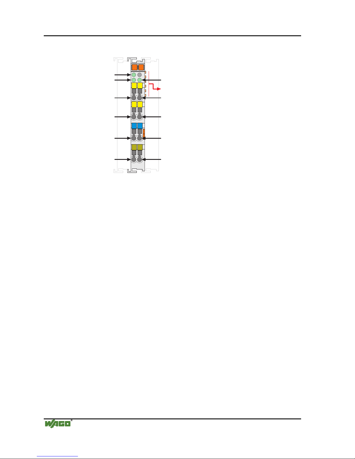
2.1.1.2 View
TxD
RTS
MM
SS
13 14
C
D
B
A
750-650
RxD
CTS
RTS
Data contacts
RxD
CTS
Common
(ground)
Shield
(screen)
TxD
Function
TxD
Shield
(screen)
RxD
Common
(ground)
Fig. 2.1.1-1: View g065000e
2.1.1.3 Description
This interface allows the connection of any device which is equipped with a
RS 232 C serial interface.
The wiring to the communication partner is made by the connections TxD,
RxD, if necessary RTS and CTS as well as ground (earth).
The shield (screen) is directly connected to the carrier rail.
The interface works in accordance with the TIA/EIA-232-F, CCITT V.28/DIN
66259-1 standard.
The connected device may directly communicate over the fieldbus coupler/controller with the control unit. The active communication channel works
independently of the higher-level fieldbus system and allows full duplex
operation up to 19200 baud.
Three green LEDs signal readiness for operation and troublefree internal bus
communication as well as the condition of the signal transmission.
The RS 232 interface guarantees high interference immunity because of the
electrically isolated signals.
Any configuration of the specialty modules is possible when designing the
fieldbus node. Grouping of module types is not necessary.
Page 7

Busklemmen • 7
750-650 (/xxx-xxx) [Serial Interface RS 232 C]
WAGO-I/O-SYSTEM 750
Busklemmen
Attention
This module has no power contacts. For field supply to downstream I/O
modules, a supply module will be needed.
The serial interface module 750-650 and its variations can be used with all
couplers/controllers of the WAGO-I/O-SYSTEM 750 (except for the economy
types 750-320, -323, -324 and -327).
This description is valid from hardware and software version XXXX4108...
and up. The version is specified in the manufacturing number, which is part of
the lateral marking on the module.
Page 8

8 • 750-650 (/xxx-xxx) [Serial Interface RS 232 C]
Display Elements
WAGO-I/O-SYSTEM 750
Busklemmen
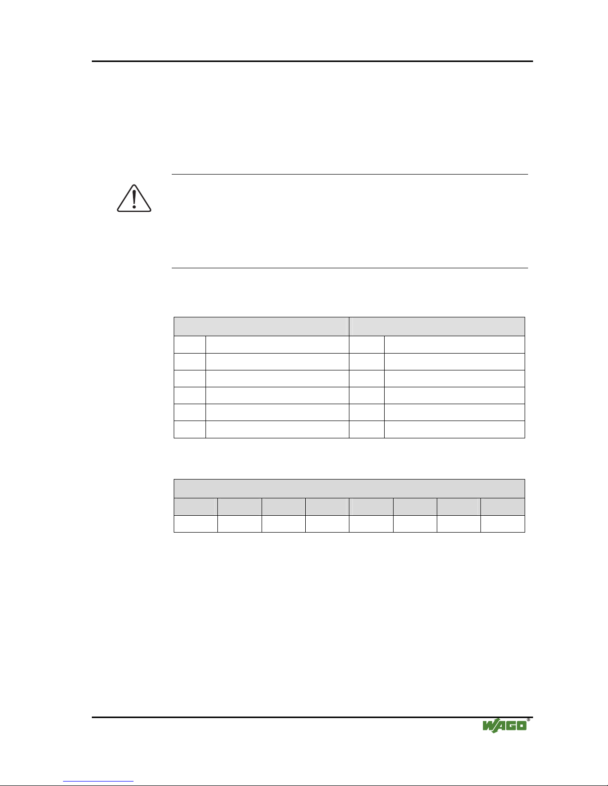
2.1.1.4 Display Elements
LED Channel State Function
off No operational readiness or the
internal data bus communication is
interrupted
A Function
green Operational readiness and trouble-free
internal data bus communication
off 1) sign al tran sfer TxD B TxD
green no signal transfer TxD
off 1) sign al tran sfer RxD D RxD
green no signal transfer RxD or open input
Fig. 2.1.1-2: Display
Elements
g065002x
1)
The pulses are so short that the off status cannot or only hardly be
recognized with the eyes.
2.1.1.5 Schematic Diagram
Shield
(screen)
TxD RxD
RTS CTS
TxD
TxD
RTS
CTS
RxD
RxD
Function
Logic
RS 232 C
Shield
(screen)
0V
0V
1
2
3
4
5
6
7
8
750-650
Fig. 2.1.1-3: Schematic Diagram g065001e
Page 9

Busklemmen • 9
750-650 (/xxx-xxx) [Serial Interface RS 232 C]
WAGO-I/O-SYSTEM 750
Busklemmen
2.1.1.6 Technical Data
Module Specific Data
Transmission channel 1 TxD / 1 RxD, full duplex
Baud rate 1200 ... 19200 baud
Bit skew < 3 %
Current consumption max. 55 mA
RS 232 C-line length max. 15 m
Buffer 120 byte in / 16 byte out
Voltage supply via system voltage DC /DC
Isolation 500 V (System/Supply)
Bit width 1 x 40 bits data
1 x 8 bits control/status
Dimensions (mm) W x H x L 12 x 64* x 100
* from upper edge of 35 DIN rail
Weight ca. 55 g
Standards and Regulations (cf. Chapter 2.2 of the Coupler/Controller Manual)
EMC-Immunity to interference (CE) acc. to EN 50082-2 (96)
EMC-Emission of interference (CE) acc. to EN 50081-1 (93)
EMC-Immunity to interference
(Ship building)
acc. to Germanischer Lloyd (01)
EMC-Emission of interference
(Ship building)
acc. to Germanischer Lloyd (01)
Approvals (cf. Chapter 2.2 of the Coupler/Controller Manual)
CULUS
(UL508)
ABS (American Bureau of Shipping)
BV (Bureau Veritas)
DNV (Det Norske Veritas) Cl. B
GL (Germanischer Lloyd) Cat. A, B, C, D
KR (Korean Register of Shipping)
LR (Lloyd's Register) Env. 1, 2, 3, 4
NKK (Nippon Kaiji Kyokai)
PRS (Polski Rejestr Statków)
RINA (Registro Italiano Navale) (only for 750-650)
CULUS
(ANSI/ISA 12.12.01) Class I Div2 ABCD T4
Page 10

10 • 750-650 (/xxx-xxx) [Serial Interface RS 232 C]
Functional description
WAGO-I/O-SYSTEM 750
Busklemmen
DEMKO / IEC I M2 / II 3 G/D Ex nA IIC T4
Conformity Marking
More Information
Detailed references to the approvals are listed in the document "Overview
Approvals WAGO-I/O-SYSTEM 750", which you can find on the CD ROM
ELECTRONICC Tools and Docs (Item-No.: 0888-0412)
or in the internet under: http://www.wago.com Documentation
WAGO-I/O-SYSTEM 750 System Description
2.1.1.7 Functional description
The interface module is designed to operate with all WAGO I/O fieldbus
couplers. The serial interface module allows the connection of RS 232Interface devices to the WAGO I/O SYSTEM. The RS 232 Interface module
can provide gateways within the fieldbus protocol. This allows serial
equipment such as printers, barcode readers, and links to local operator
interfaces to communicate directly by the fieldbus protocol with the PLC or
PC Master. This module supports no higher level of protocol. Communication
is made completely transparent to the fieldbus allowing flexibility in further
applications of the serial interface module. The communication protocols are
configured at the Master PLC or PC.
The 120 byte input buffer provides for high rates of data transmission. When
using lower rates of transmission speed you can collect the received data, with
less priority, without loosing data.
The 16 byte output buffer provides for faster transmission of larger data
strings.
Attention
The data transmission takes place at 9.600 baud. 1 startbit, 8 databits and 1
stopbit will be transmitted. No parity is available. The user controls data via
the RTS and CTS signals. These signals are generated in the module
depending on the loading status of the buffers. These controls can be
deactivated by means of an external jumper. RTS and CTS are to be
connected.
Attention
For testing purposes the Windows terminal emulation can be used. A
cable with a 9- pole sub-D socket is required. Pin 5 is connected to input
"common". Pin 2 is connected to TxD and Pin 3 to RxD. RTS and CTS of
the module are connected. A hardwarehandshake between the terminal
emulation and the PLC is not possible.
Page 11
Busklemmen • 11
750-650 (/xxx-xxx) [Serial Interface RS 232 C]
WAGO-I/O-SYSTEM 750
Busklemmen
2.1.1.8 Process Image
Using the I/O module 750-650, a 6 byte input and output process image can be
transferred to the fieldbus coupler / controller via one logical channel. The
transfer of the data to be transmitted and the received data is made via 5
output and 5 input bytes (D0 ... D4). 1 Control byte (C) and 1 Status byte (S)
are used to control the floating data.
Attention
The representation of the process data of some I/O modules or their variations
in the process image depends on the fieldbus coupler/-controller used. Please
take this information as well as the particular design of the respective
control/status bytes from the section "Fieldbus Specific Design of the Process
Data" included in the description concerning the process image of the
corresponding coupler/controller.
Up to 5 characters which have been received via interface can be stored in the
input bytes. The output bytes will contain the characters to be sent.
Input data Output data
S Status byte C Control byte
D0 Input byte 0 D0 Output byte 0
D1 Input byte 1 D1 Output byte 1
D2 Input byte 2 D2 Output byte 2
D3 Input byte 3 *), **) D3 Output byte 3 *), **)
D4 Input byte 4 **) D4 Output byte 4 **)
*) with variations with 4 Data bytes, **) with variations with 5 Data bytes
Control byte
Bit 7 Bit 6 Bit 5 Bit 4 Bit 3 Bit 2 Bit 1 Bit 0
0 OL 2 OL 1 OL 0 0 IR RA TR
TR Transmit request
RA Receive acknowledge
IR Initialization request
OL 0,
OL 1,
OL 2
Output length (number of characters to be sent, which have been stored in the
output bytes)
0 Constant value must always be 0.
Page 12

12 • 750-650 (/xxx-xxx) [Serial Interface RS 232 C]
Process Image
WAGO-I/O-SYSTEM 750
Busklemmen
Status byte
Bit 7 Bit 6 Bit 5 Bit 4 Bit 3 Bit 2 Bit 1 Bit 0
0 IL 2 IL 1 IL 0 BUF_F IA RR TA
TA Transmit acknowledge
RR Receive request
IA Initialization acknowledge
BUF_F Buffer full
IL 0,
IL 1,
IL 2
Input length (number of received characters , which have been stored in the
input data)
0 Constant value must always be 0.
Page 13

Busklemmen • 13
750-650 (/xxx-xxx) [Serial Interface RS 232 C]
WAGO-I/O-SYSTEM 750
Busklemmen
2.1.1.9 Datatransfer
With the control and status byte the controlling of the sending and receive
mode takes place. Requests are indicated by a bit change of state. An assigned
bit indicates execution by adopting the value of the request bit.
Initialization of the module:
Set IR bit in the control byte
Initialization of the module
Transmit/receive functions are blocked
Output/input buffers are erased
Serial interface module will load its configuration data
Transmitting data:
TRTA: put characters into output bytes 0 to 2
Amount of characters is specified in OL0 to OL2
TR is inverted and read out
characters are put into output buffer if TR=TA
Receiving data:
RRRA: data in input bytes 0 to 2 characters are available
Amount of characters is specified in IL0 to IL2
Characters in IL0 to IL2 are read out
RA is inverted and read out
All characters are read when RR=RA
The transmitting and receiving of data can be done simultaneously. The
initialization request has priority and will stop transmitting and receiving of
data immediately.
Attention
Resetting the initialization bit can be performed with the following message.
Message: input buffer full (Bit 3)
Input buffer is full. Data which is being currently received is now lost.
Page 14
14 • 750-650 (/xxx-xxx) [Serial Interface RS 232 C]
Datatransfer
WAGO-I/O-SYSTEM 750
Busklemmen
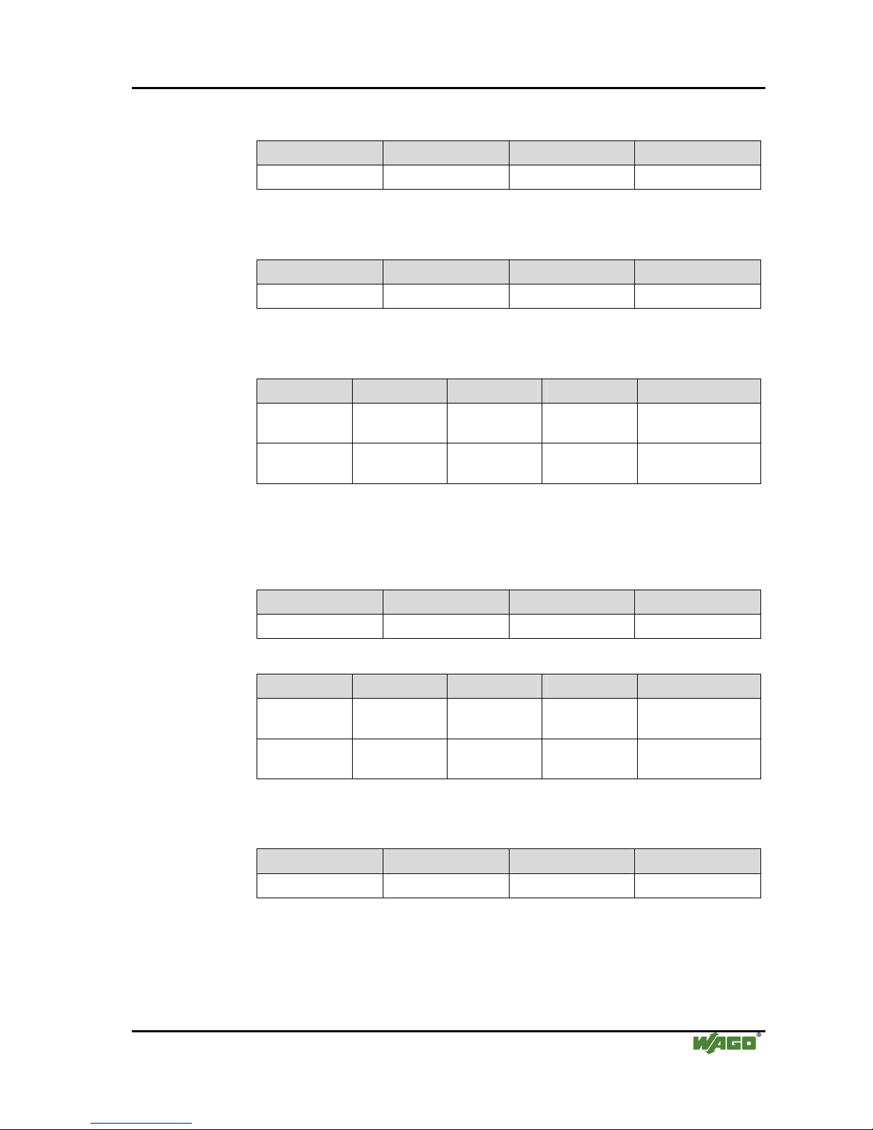
2.1.1.9.1 Example
The module is initialized.
The initialization bit in the control byte is set.
Output byte 0 Control byte Output byte 2 Output byte 1
0x00 '0000.0100' 0x00 0x00
After the initialization has been executed, the status byte will give back
000.0100.
Input byte 0 Status byte Input byte 2 Input byte 1
XX '0XXX. X0XX' XX XX Module is still being
reset.
XX '0XXX. X1XX' XX XX Initialization
completed.
Sending of the data string "Hello”
The first 3 characters and the buffer length of 3 are transmitted.
Output byte 0 Control byte Output byte 2 Output byte 1
"H" (0x48) '0011.0000' "1" (0x6C) "a" (0x60)
The transmission request bit (TR) is inverted.
Output byte 0 Control byte Output byte 2 Output byte 1
"H" '0011.0001' "1" "a"
As soon as TR=TA, the rest of the data can be sent.
Input byte 0 Status byte Input byte 2 Input byte 1
XX '0XXX.XXX0' XX XX The data is still
being transferred.
XX '0XXX.XXX1' XX XX Data transfer
completed.
Page 15
Busklemmen • 15
750-650 (/xxx-xxx) [Serial Interface RS 232 C]
WAGO-I/O-SYSTEM 750
Busklemmen
The last 2 characters and the buffer length of 2 are transmitted.
Output byte 0 Control byte Output byte 2 Output byte 1
"1" '0010.0001' XX "o" (0x6F)
The transmission request bit (TR) is inverted.
Output byte 0 Control byte Output byte 2 Output byte 1
"1" '0010.0000' XX "o"
As soon as TA = TR, the data has been transferred to the output buffer.
Input byte 0 Status byte Input byte 2 Input byte 1
XX '0XXX. XXX1' XX XX The data is still
being transferred.
XX '0XXX. XXX0' XX XX Data transfer
completed.
Receiving the character chain "WAGO”
As soon as RARR, the input bytes contain data.
Output byte 0 Control byte Output byte 2 Output byte 1
XX '0XXX.000X' XX XX
Input byte 0 Status byte Input byte 2 Input byte 1
XX '0XXX. 0X0X' XX XX No received data
available.
"W" '0011.0X1X' "G" "A" The information is in
the input bytes.
After the 3 characters have been processed, RA is inverted.
Output byte 0 Control byte Output byte 2 Output byte 1
XX '0XXX.001X' XX XX
Page 16

16 • 750-650 (/xxx-xxx) [Serial Interface RS 232 C]
Datatransfer
WAGO-I/O-SYSTEM 750
Busklemmen
If RARR, the receiving of additional characters will continue.
Input byte 0 Status byte Input byte 2 Input byte 1
XX '0XXX. 0X1X' XX XX No received data
available.
'O' '0001.0X0X' XX XX The information is in
the input bytes.
After the characters have been processed, RA is inverted.
Output byte 0 Control byte Output byte 2 Output byte 1
XX '0XXX.000X' XX XX
Note
An X indicates that this particular value has no importance.
XX indicates that the whole value has no importance.
Page 17

Busklemmen • 17
750-650 (/xxx-xxx) [Serial Interface RS 232 C]
WAGO-I/O-SYSTEM 750
Busklemmen
2.1.1.10 Adjustable Variation 750-650/003-000
The serial interface module 750-650/003-000 may be parameterized with the
software tool WAGO-I/O-CHECK 2 (Item-No.: 759-302).
The presetting is Baud rate: 9600 baud, data bits: 8, Parity: none, stop bits: 1.
In this mode of operation the module has the same behavior and also the same
process values as the base module 750-650. If another mode of operation is
selected by changing the parameters, then the module behaves according to
the variation with the selected mode of operation.
The parameter dialog box in WAGO I/O CHECK 2 offers selection fields for
the available settings of this I/O module.
The following description is valid for software version 41.
Select box Available settings
Baudrate 1200 Baud / 2400 Baud / 4800 Baud /
9600 Baud* / 19200 Baud / 38400 Baud /
57600 Baud
Data frame 7 Data bits, Even Parity / 7 Data bits, Odd Parity /
8 Data bits, No Parity* / 8 Data bits, Even Parity /
8 Data bits, Odd Parity
Stop bits 1* / 2 Number of stop bits
Standard (see mapping-tables in the coupler- /
controller-manual)
Output format
Alternative* (see mapping-tables in the coupler- /
controller-manual)
Data bytes (BK) 3* / 4 / 5 Number of data bytes (see mapping-tables
in the coupler- / controller-manual)
Disable Hardware handshake is not active RTS / CTS
Enable* Hardware handshake is active
RTS is set if receive buffer of the module
contains more than 114 characters.
RTS is reset if receive buffer of the
module contains less than 104 characters.
If CTS is set the module does not send
any data.
Normal* State byte and data bytes are transmitted
in the same KBUS cycle
Copy State Byte
Retarded The state byte is transmitted one KBUS
cycle later after data bytes are transmitted.
This causes a lower data transmission
rate.
XON / XOFF
(send)
OFF* The module does not support the
XON/XOFF-protocol when sending data.
Page 18

18 • 750-650 (/xxx-xxx) [Serial Interface RS 232 C]
Adjustable Variation 750-650/003-000
WAGO-I/O-SYSTEM 750
Busklemmen
Select box Available settings
ON The module supports the XON/XOFF-
protocol when sending data.
The module sends the data delivered by
the PLC until the XOFF (DC3==0x13)
character is received from the communication partner.
The transmission is halted until the XON
(DC1==0x11) character is received.
OFF* The module does not support the
XON/XOFF-protocol when receiving
data.
XON / XOFF
(receive)
ON The module supports the XON/XOFF-
protocol when receiving data.
The module sends the XOFF control
character if the receive buffer contains
more than 110 characters. XON is sent
once XOFF has been sent and the buffer
contains less than 18 bytes.
OFF* Continuous data transmission from FIFO
is not active.
Continuous
Send
ON Continuous data transmission from FIFO
is active.
The send buffer is filled by the PLC (up
to 16 bytes). The buffer content is sent
with the rising edge in bit 3 of the control
byte. Acknowledgement of the
transmitted data is done by setting the bit
2 of the status byte.
Bit 2 of the status byte is reset when bit 3
of the control byte is set.
* default setting
More Information
Detailed Information about the parameterizing this module can be found in
the manual for the software tool WAGO-I/O-CHECK or in the Internet
under: http://www.wago.com .
Page 19

Busklemmen • 19
750-650 (/xxx-xxx) [Serial Interface RS 232 C]
WAGO-I/O-SYSTEM 750
Busklemmen
Page 20

WAGO Kontakttechnik GmbH & Co. KG
Postfach 2880 • D-32385 Minden
Hansastraße 27 • D-32423 Minden
Phone: 05 71/8 87 – 0
Fax: 05 71/8 87 – 1 69
E-Mail: info@wago.com
Internet: http://www.wago.com
 Loading...