

Page 1
Pos: 2 /Dokumentation allgemein/Einband/Einband Handbuch - Deckblatt oh ne V ari ant enfel d ( Sta ndar d) @ 9 \mod_1285229289866_0.docx @ 64941 @ @ 1
Manual
WAGO-I/O-SYSTEM 750
Pos: 3 /Alle Seri en (Allgemeine Module)/Hinweise zur Dokumentation/Impressum für Standardhandbücher - allg. Angaben, Anschr iften, Telef onnu mmern un d E-Mail- Adres sen @ 3\mod_1219151118203_21.docx @ 21060 @ @ 1
Bluetooth® RF-Transceiver
750-644
Version 2.0.0, valid from FW/HW Version 03/03
Page 2

2 WAGO-I/O-SYSTEM 750
750-644 Bluetooth
®
RF-Transceiver
© 2014 by WAGO Kontakttechnik GmbH & Co. KG
All rights reserved.
WAGO Kontakttechnik GmbH & Co. KG
Hansastraße 27
D-32423 Minden
Phone: +49 (0) 571/8 87 – 0
Fax: +49 (0) 571/8 87 – 1 69
E-Mail: info@wago.com
Web: http://www.wago.com
=== Ende der Li st e für Te xtm arke Ei nba nd_ vorn e ===
Technical Support
Phone: +49 (0) 571/8 87 – 5 55
Fax: +49 (0) 571/8 87 – 85 55
E-Mail: support@wago.com
Every conceivable measure has been taken to ensure the accuracy and
completeness of this documentation. However, as errors can never be fully
excluded, we always appreciate any information or suggestions for improving the
documentation.
E-Mail: documentation@wago.com
We wish to point out that the software and hardware terms as well as the
trademarks of companies used and/or mentioned in the present manual are
generally protected by trademark or patent.
Manual
Version 2.0.0, valid from FW/HW Version 03/03
Page 3

WAGO-I/O-SYSTEM 750 Table of Contents 3
750-644 Bluetooth
Pos: 5 /Do kume ntati on allg em ein /Ver zeic hni sse /Inh alts ver z eich nis - Ü bers chrif t oG und Ver zeic hnis @ 3\ mod_1219151230875_21.docx @ 21063 @ @ 1
®
RF-Transceiver
Table of Contents
1 Notes about this Documentation ................................................................. 8
1.1 Validity of this Documentation ................................................................. 8
1.2 Revision History ........................................................................................ 8
1.3 Copyright ................................................................................................... 8
1.4 Symbols ..................................................................................................... 9
1.5 Number Notation ..................................................................................... 11
1.6 Font Conventions .................................................................................... 11
2 Important Notes ......................................................................................... 12
2.1 Legal Bases ............................................................................................. 12
2.1.1 Subject to Changes ............................................................................. 12
2.1.2 Personnel Qualifications ..................................................................... 12
2.1.3 Use of the 750 Series in Compliance with Underlying Provisions .... 12
2.1.4 Technical Condition of Specified Devices ......................................... 13
2.2 Safety Advice (Precautions) .................................................................... 14
3 Bluetooth® Technology............................................................................... 16
3.1 Piconet ..................................................................................................... 16
3.2 Profile and Identification ......................................................................... 16
3.3 Security ................................................................................................... 17
3.4 Definition of Terms ................................................................................. 17
4 Device Description ..................................................................................... 19
4.1 View ........................................................................................................ 22
4.2 Connectors ............................................................................................... 23
4.2.1 Data Contacts/Internal Bus ................................................................. 23
4.2.2 Power Jumper Contacts/Field Supply ................................................ 24
4.3 Antenna ................................................................................................... 26
4.4 Display Elements .................................................................................... 28
4.4.1 “Configuration” Mode ........................................................................ 28
4.4.2 “Real-Time Communication” Mode, Master ..................................... 28
4.4.3 “Real-Time Communication” Mode, Slave ....................................... 29
4.4.4 “Ad-hoc Communication” Mode ....................................................... 30
4.5 Schematic Diagram ................................................................................. 31
4.6 Technical Data ........................................................................................ 32
4.6.1 Device ................................................................................................. 32
4.6.2 Supply ................................................................................................. 32
4.6.3 Communication .................................................................................. 32
4.6.4 Configuration and Diagnostics ........................................................... 33
4.6.5 Climatic Environmental Conditions ................................................... 33
4.6.6 Connection Type ................................................................................ 33
4.7 Approvals ................................................................................................ 34
4.8 Standards and Guidelines ........................................................................ 35
5 Function Description ................................................................................. 36
5.1 Operating Modes ..................................................................................... 36
5.1.1 “Configuration” Mode ........................................................................ 37
5.1.2 “Real-Time Communication” Mode .................................................. 37
5.1.3 “Ad-hoc Communication” Mode ....................................................... 37
Manual
Version 2.0.0, valid from FW/HW Version 03/03
Page 4

4 Table of Contents WAGO-I/O-SYSTEM 750
750-644 Bluetooth
®
RF-Transceiver
5.2 Radio Interface ........................................................................................ 37
5.2.1 Net Forming........................................................................................ 38
5.2.1.1 Slots, Slot Addresses ..................................................................... 38
5.2.1.2 Scan for Remote Devices ............................................................... 38
5.2.2 Operation as a Master in “Real-Time Communication” Mode .......... 39
5.2.3 Operation as a Slave in “Real-Time Communication” Mode ............ 40
5.2.4 Operation as a Master in “Ad-hoc Communication” Mode ............... 40
5.2.5 Operation as a Slave in “Ad-hoc Communication” Mode ................. 41
5.2.6 Visibility and Connectivity................................................................. 41
5.2.7 Encryption .......................................................................................... 42
5.2.8 Authentication .................................................................................... 42
5.2.9 Coexistence......................................................................................... 42
5.3 Startup Behavior ...................................................................................... 43
5.4 Factory Settings ....................................................................................... 43
5.5 Timing ..................................................................................................... 44
6 Process Image ............................................................................................. 45
6.1 Control/Status Byte (C/S Byte) ............................................................... 47
6.2 Prozess Data ............................................................................................ 47
6.2.1 “Real-Time Communication” Mode .................................................. 48
6.2.2 “Ad-hoc Communication” Mode ....................................................... 50
6.3 Higher-Level Configuration Protocols .................................................... 52
6.3.1 Mailbox............................................................................................... 54
6.3.2 Process Data Overlaid by Mailbox ..................................................... 58
6.3.3 Register Communication .................................................................... 60
6.3.4 Parameter Channel.............................................................................. 61
6.3.4.1 Parameter Data (Register 56) ......................................................... 62
6.3.4.2 Communication Control (Register 57) .......................................... 62
6.3.4.3 Parameter Sets ............................................................................... 63
6.3.4.4 Process of Parameter Transmission ............................................... 63
7 Mounting ..................................................................................................... 67
7.1 Mounting Sequence ................................................................................. 67
7.2 Inserting and Removing Devices ............................................................ 68
7.2.1 Inserting I/O Module .......................................................................... 68
7.2.2 Removing the I/O Module .................................................................. 69
7.3 Mount Antenna ........................................................................................ 70
7.3.1 Scope of Application .......................................................................... 71
7.3.2 Range in Open Area ........................................................................... 71
8 Commissioning ........................................................................................... 74
8.1 Configuration and Parameterization with WAGO-I/O-CHECK ............ 74
8.1.1 Title Bar .............................................................................................. 75
8.1.2 Toolbar ............................................................................................... 75
8.1.3 Navigation .......................................................................................... 76
8.1.4 Operating Mode and Role Assignment .............................................. 77
8.1.5 Parameterization Mode ....................................................................... 78
8.1.5.1 Settings .......................................................................................... 79
8.1.5.2 Net Forming ................................................................................... 80
8.1.5.3 PI Mapping .................................................................................... 82
8.1.5.4 Block Transfer ............................................................................... 85
Manual
Version 2.0.0, valid from FW/HW Version 03/03
Page 5

WAGO-I/O-SYSTEM 750 Table of Contents 5
750-644 Bluetooth
®
RF-Transceiver
8.1.5.5 Diagnostics .................................................................................... 87
8.1.6 Status Display ..................................................................................... 90
8.2 Configuration and Parameterization via Process Image ......................... 90
9 Example Configuration ............................................................................. 91
9.1 Example Configurations via WAGO-I/O-CHECK ................................. 91
9.1.1 Startup with the Bluetooth® Parameterization Dialog ........................ 91
9.1.1.1 Network Configuration .................................................................. 91
9.1.1.2 Startup of the 750-644 I/O Modules .............................................. 92
9.1.1.2.1 Configuring Slaves via “Net Forming” ..................................... 92
9.1.1.2.2 Configuring the Master via “Net Forming” .............................. 95
9.1.1.2.3 Assigning Process Data ............................................................. 97
9.1.1.3 Testing Process Data Exchange ..................................................... 98
9.1.2 Startup via Mailbox Commands in the Process Data Dialog ............. 98
9.1.2.1 Network Configuration .................................................................. 99
9.1.2.2 Startup of the 750-644 I/O Modules .............................................. 99
9.1.2.2.1 Switching On the Mailbox ........................................................ 99
9.1.2.2.2 Resetting 750-644 I/O Modules to Factory Settings ............... 100
9.1.2.2.3 Specifying the Master ............................................................. 100
9.1.2.2.4 Querying MAC IDs ................................................................. 101
9.1.2.2.5 Loading the MAC IDs of the Slave in the Device List
of the Master ........................................................................... 101
9.1.2.2.6 Loading the MAC ID of the Master in the Device Lists
of the Slaves ............................................................................ 103
9.1.2.2.7 Binding Slaves ........................................................................ 103
9.1.2.2.8 Binding the Master .................................................................. 104
9.1.2.2.9 Setting “Communication” Mode for Master and Slaves ......... 105
9.2 Connecting with WAGO 757-801 ........................................................ 106
9.2.1 Preparing a 757-801 ......................................................................... 106
9.2.2 Preparing a 750-644 ......................................................................... 106
9.2.3 Exchanging Data .............................................................................. 106
9.3 Connecting to an Android Smartphone ................................................. 108
9.4 Connecting to Windows 7 PC ............................................................... 110
9.4.1 Preparing a PC .................................................................................. 110
9.4.2 Preparing a 750-644 I/O Module ...................................................... 110
9.4.3 Adding the 750-644 I/O Module to the PC Device List ................... 111
9.4.4 Starting Data Exchange via Terminal Program ................................ 112
10 Diagnostics ................................................................................................ 114
10.1 Diagnostics in WAGO-I/O-CHECK ..................................................... 114
10.2 Diagnostics via Process Image or LED Display ................................... 116
10.2.1 No Field Supply ................................................................................ 116
10.2.2 No Radio Connection ....................................................................... 117
10.2.3 Signal Status of the Radio Connections ........................................... 117
10.2.4 Validity of Process Data ................................................................... 118
10.2.5 Topicality of Process Data ................................................................ 119
10.2.5.1 Topicality Not Specified for Known Reasons ............................. 119
10.2.5.2 Topicality Not Specified for Other Reasons ................................ 119
10.2.6 Configuration Errors ......................................................................... 120
Manual
Version 2.0.0, valid from FW/HW Version 03/03
Page 6

6 Table of Contents WAGO-I/O-SYSTEM 750
750-644 Bluetooth
®
RF-Transceiver
11 Use in Hazardous Environments ............................................................ 121
11.1 Marking Configuration Examples ......................................................... 121
11.1.1 Marking for Europe According to CENELEC and IEC ................... 121
11.1.2 Marking for America according to NEC 500 ................................... 125
11.2 Installation Regulations ......................................................................... 126
11.2.1 Special Conditions for Safe Operation of the ATEX and
IEC Ex (acc. DEMKO 08 ATEX 142851X and
IECEx PTB 07.0064)........................................................................ 126
11.2.2 Special conditions for safe use
(ATEX Certificate TÜV 07 ATEX 554086 X) ................................ 127
11.2.3 Special conditions for safe use
(IEC-Ex Certificate TUN 09.0001 X) .............................................. 128
11.2.4 ANSI/ISA 12.12.01 .......................................................................... 129
12 Appendix ................................................................................................... 130
12.1 Mailbox Commands .............................................................................. 130
12.1.1 Übersicht sortiert nach Gruppen und Opcodes ................................. 130
12.1.2 Overview Sorted According Mailbox Commands ........................... 134
12.2 Return Values of Mailbox Commands .................................................. 137
12.3 Reference for Mailbox Commands ....................................................... 138
12.3.1 General Commands .......................................................................... 139
12.3.1.1 No Task ........................................................................................ 139
12.3.2 Block Transfer .................................................................................. 139
12.3.2.1 Download Start of a Block .......................................................... 139
12.3.2.2 Continuing Block Download or Upload ...................................... 141
12.3.2.3 Stopping Block Download or Upload .......................................... 142
12.3.3 Maintenance and Firmware .............................................................. 144
12.3.3.1 Warm Booting the Bluetooth® Subsystem ................................... 144
12.3.3.2 Save Configuration with Subsequent Warm Boot ....................... 144
12.3.3.3 Reading the Host Firmware Version ........................................... 145
12.3.3.4 Reading the Firmware Version of the Baseband Controller ........ 146
12.3.4 Process Image (PI) ............................................................................ 147
12.3.4.1 Determining the Size of a Slot for Data Transfer in the
Master PI ...................................................................................... 147
12.3.4.2 Querying Remote Process Image Parameters within the
Master PI ...................................................................................... 148
12.3.5 Device Configuration ....................................................................... 149
12.3.5.1 Reading Local Device Names...................................................... 149
12.3.5.2 Wiriting Local Device Names ..................................................... 150
12.3.5.3 Reading Local MAC IDs ............................................................. 151
12.3.5.4 Reading a Local WAGO Device Class ........................................ 152
12.3.5.5 Writing a Local Device Class ...................................................... 153
12.3.5.6 Reading a Local Operating Mode ................................................ 153
12.3.5.7 Setting the Local Operating Mode ............................................... 154
12.3.5.8 Reading the Local Encryption Mode ........................................... 155
12.3.5.9 Setting the Local Encryption Mode ............................................. 156
12.3.5.10 Reading the Local Authentication Mode ..................................... 157
12.3.5.11 Setting Local Authentication Mode ............................................. 157
12.3.5.12 Reading the Local Bluetooth® Password ..................................... 159
12.3.5.13 Writing the Local Bluetooth® Password ...................................... 160
Manual
Version 2.0.0, valid from FW/HW Version 03/03
Page 7

WAGO-I/O-SYSTEM 750 Table of Contents 7
750-644 Bluetooth
®
RF-Transceiver
12.3.5.14 Erasing Local Authorization ........................................................ 161
12.3.5.15 Reading the Length of the Flash Configuration .......................... 162
12.3.5.16 Reading the Roll of the Local Device .......................................... 162
12.3.5.17 Setting the Role of the Local Device ........................................... 163
12.3.5.18 Restoring Factory Settings ........................................................... 164
12.3.5.19 Reading the Maximum Transmission Power ............................... 164
12.3.5.20 Setting the Maximum Transmission Power ................................. 165
12.3.5.21 Reading the Default Transmission Power ................................... 166
12.3.5.22 Setting the Default Transmission Power ..................................... 166
12.3.6 Network ............................................................................................ 168
12.3.6.1 Scanning for a Remote Device in the Wireless Network ............ 168
12.3.6.2 Reading the MAC ID of a Remote Device .................................. 169
12.3.6.3 Reading the Device Names of a Remote Device ......................... 170
12.3.6.4 Entering a Device in the Table of Allowed Devices ................... 172
12.3.6.5 Reading a Remote Device from the Table of Allowed Devices .. 173
12.3.6.6 Granting Access Permission to a Device ..................................... 174
12.3.6.7 Deleting Access Permission for a Device .................................... 175
12.3.6.8 Reading Access Permission for Remote Devices ........................ 176
12.3.6.9 Reading QoS Settings .................................................................. 177
12.3.6.10 Setting QoS Settings .................................................................... 178
12.3.6.11 Reading Back the Time Setting – Between Two Attempts to
Establish a Connection ................................................................ 179
12.3.6.12 Setting the Time Setting – Between Two Attempts to Establish
a Connection ................................................................................ 180
12.3.6.13 Reading the User-Friendly Name of an Allowed Device ............ 181
12.3.6.14 Writing the User-Friendly Name of an Allowed Device ............. 182
12.3.7 Diagnostics ....................................................................................... 184
12.3.7.1 Reading the Status of the Local I/O Module ............................... 184
12.3.7.2 Reading the Status of the Wireless Network ............................... 185
12.3.7.3 Reading Diagnostic Information .................................................. 186
12.3.7.4 Establishment of the Object ID .................................................... 189
12.3.7.5 Reading the Connection Quality .................................................. 191
12.3.7.6 Reading the Signal Strength for a Connection ............................ 192
12.3.7.7 Reading Available Hopping Channels ......................................... 194
12.3.7.8 Setting an LED ............................................................................ 195
12.3.7.9 Mirroring a Mailbox for Test Purposes ....................................... 197
12.3.7.10 Reading the Operating Time of the I/O Module .......................... 197
12.4 Extended Register Structure (Configuration Block) ............................. 198
13 Glossary .................................................................................................... 201
List of Figures .................................................................................................... 213
List of Tables ...................................................................................................... 215
=== Ende der Li st e für Te xtm arke Ver zeic hni s_v or ne == =
Manual
Version 2.0.0, valid from FW/HW Version 03/03
Page 8
8 Notes about this Documentation WAGO-I/O-SYSTEM 750
Table 1: Revision history
Document
Equipment version
Hardware
Software
1.0.0
01
01
Initial draft
2.0.0
03
03
Reorganization after functional expansion of the
“Ad-hoc communication ” mode
750-644 Bluetooth
Pos: 7 /Alle S erie n (Al lge mei ne M odul e) /Üb ersc hri ften für all e S erie n/Hi n weis zur Do kum enta tio n/Hin wei se z ur Do kume nt atio n - Üb ers chr ift 1 @ 4 \mod_1237987661750_21.docx @ 29029 @ 1 @ 1
®
RF-Transceiver
1 Notes about this Documentation
Pos: 8 /Alle S erie n (Al lge mei ne M odul e) /Hin wei se z ur Dok umen ta tio n/Hi nweis e/H in weis : D oku ment atio n a uf bewahr e n @ 4\mod_1237987339812_21.docx @ 29026 @ @ 1
Keep this documentation!
The operating instructions are part of the product and shall be kept for the entire
lifetime of the device. They shall be transferred to each subsequent owner or user
of the device. Care must also be taken to ensure that any supplement to these
instructions are included, if applicable.
Pos: 9 /Alle S erie n (Al lge mei ne M odul e) /Üb ersc hri ften für all e S erie n/Hi n weis zur Do kum enta tio n/Gül tig kei ts ber eich - Über schr ift 2 @ 12\mod_1338912448776_21.docx @ 96469 @ 2 @ 1
1.1 Validity of this Documentation
Pos: 10 /Ser ie 75 0 (WA GO-I/ O-SYS TEM )/H in weis e z ur D okum ent ati on/ Gül tigk eits ber eic h/G ültig k eits ber eich Dok um entation Busklemme 750-xxxx, ohne V aria nten ang abe @ 14\mod_1358944037947_21.docx @ 109346 @ @ 1
This documentation is only applicable to the I/O module 750-644
(Bluetooth® RF-Transceiver).
Pos: 11 /Ser ie 75 0 (WA GO-I/ O-SYS TEM )/H in weis e z ur D okum ent ati on/Hi n weis e/Ac ht ung : Hin wei s z ur D oku ment ati on B us kle mme n 75 0-xxxx @ 4\mod_1237986979656_21.docx @ 29023 @ @ 1
The I/O module 750-644 shall only be installed and operated according to the
instructions in this manual and in the manual for the used fieldbus
coupler/controller.
Consider power layout of the WAGO-I/O-SYSTEM 750!
In addition to these operating instructions, you will also need the manual for the
used fieldbus coupler/controller, which can be downloaded at www.wago.com.
There, you can obtain important information including information on electrical
isolation, system power and supply specifications.
Pos: 12 /All e S eri en ( Allg emei n e Mod ule) /Ü ber schri fte n f ür al le Ser ien/ Hin weis zur D oku ment ati on/Ä nder ung shi st orie - Über sc hrift 2 @ 6\ mod_1255513312687_21.docx @ 42790 @ 2 @ 1
1.2 Revision History
Pos: 13 /D okum ent atio n al lge mein/ Test /Al ex/ 750- 644/ Änd erung shis tori e - 750-644 @ 15\mod_1371728027050_21.docx @ 123812 @ @ 1
version
Change
Pos: 14.1 /Al l e Ser ien ( Al lge mei ne M od ule)/H i nweis e z ur D ok ume ntati on /Urh eber sc hutz au sführ li ch @ 4\mod_1235565145234_21.docx @ 27691 @ 2 @ 1
1.3 Copyright
This Manual, including all figures and illustrations, is copyright-protected. Any
further use of this Manual by third parties that violate pertinent copyright
provisions is prohibited. Reproduction, translation, electronic and phototechnical
filing/archiving (e.g., photocopying) as well as any amendments require the
written consent of WAGO Kontakttechnik GmbH & Co. KG, Minden, Germany.
Non-observance will involve the right to assert damage claims.
Pos: 14.2 /Dokumentation allgemein/Glieder ungselemente/---Seitenwechsel--- @ 3\mod_1221108045078_0.docx @ 21810 @ @ 1
Manual
Version 2.0.0, valid from FW/HW Version 03/03
Page 9
WAGO-I/O-SYSTEM 750 Notes about this Documentation 9
750-644 Bluetooth
Pos: 14.3 /Al l e Ser ien ( Al lge mei ne M od ule)/Ü ber sc hrift e n für all e S eri en/Hi nw eis z ur D o kume ntati on /Sy mb ole - Ü ber schr if t 2 @ 13\ mod_1351068042408_21.docx @ 105270 @ 2 @ 1
®
RF-Transceiver
1.4 Symbols
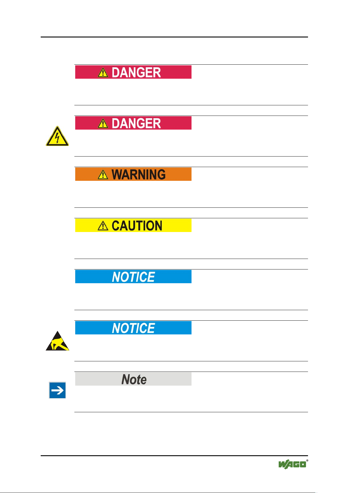
Pos: 14.4.1 /All e Serie n (All gemei ne M od ule)/ Wic htig e E rlä uter ung en/ Sic herh eits - und sonstige Hinweise/Gefahr/Gefahr: _Warnung vor Personenschäden allgemein_ - Erläuterung @ 13\ mod_1343309450020_21.docx @ 101029 @ @ 1
Personal Injury!
Indicates a high-risk, imminently hazardous situation which, if not avoided, will
result in death or serious injury.
Pos: 14.4.2 /All e Serie n (All gemei ne Mod ule)/ Wichtig e Erlä uteru ngen/ Sich erheits - und sonsti ge Hinw eise/ Gefahr /Gef ahr: _ Warnu ng vor Per sonen schä den durc h elekt risc hen Stro m_ - Erläuterung @ 13\mod_1343309694914_21.docx @ 101030 @ @ 1
Personal Injury Caused by Electric Current!
Indicates a high-risk, imminently hazardous situation which, if not avoided, will
result in death or serious injury.
Pos: 14.4.3 /All e Serie n (All gemei ne Mod ule)/ Wichtig e Erlä uteru ngen/ Sich erheits - und sons ti ge Hi nw eis e/W arn ung/ War nung : _ Warn ung vor P erso nensc h äde n allg em ei n_ - Erläuterung @ 13\mod_1343309877041_21.docx @ 101035 @ @ 1
Personal Injury!
Indicates a moderate-risk, potentially hazardous situation which, if not avoided,
could result in death or serious injury.
Pos: 14.4.4 /All e Serie n (All gemei ne Mod ule)/ Wichtig e Erlä uteru ngen/ Sich erheits - und sons ti ge Hi nw eis e/Vor sic ht /Vor sich t: _War nung v or Pers onensc häde n allge mein _ - Erläuterung @ 13\mod_1343310028762_21.docx @ 101038 @ @ 1
Personal Injury!
Indicates a low-risk, potentially hazardous situation which, if not avoided, may
result in minor or moderate injury.
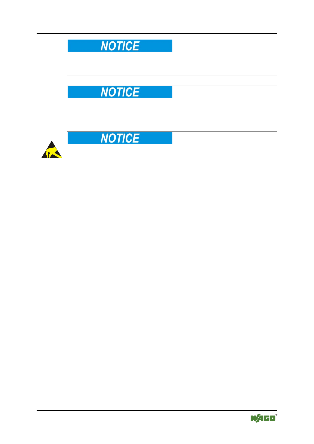
Pos: 14.4.5 /All e Serie n ( All ge meine Mo dul e)/ Wic htige Erl äut eru nge n/Si ch erhei ts- und sonstige Hinweise/Achtung/Achtung: _Warnung vor Sachschäden allgemein_ - Erläuterung @ 13\mod_1343310134623_21.docx @ 101041 @ @ 1
Damage to Property!
Indicates a potentially hazardous situation which, if not avoided, may result in
damage to property.
Pos: 14.4.6 /All e Serie n (All gemei ne Mod ule)/ Wichtig e Erlä uteru ngen/ Sich erheits - und sonstige Hinweise/Achtung/ Achtung: _Warnung vor Sachschäden durch elektrostatische Aufladung_ - Erlä uteru ng @ 13\mod_1343310227702_21.docx @ 101044 @ @ 1
Damage to Property Caused by Electrostatic Discharge (ESD)!
Indicates a potentially hazardous situation which, if not avoided, may result in
damage to property.
Pos: 14.4.7 /All e Serie n (All gemei ne Mod ule)/ Wichtig e Erlä uteru nge n/Si cher heits - und sonstige Hinweise/Hinweis/Hinweis: _Wichtiger Hinweis allgemein_ - Erläuterung @ 13\mod_1343310326906_21.docx @ 101047 @ @ 1
Important Note!
Indicates a potential malfunction which, if not avoided, however, will not result in
damage to property.
Pos: 14.4.8 /All e Serie n (All gemei ne Mod ule)/ Wichtig e Erlä uteru ngen/ Sich erheits - und sons ti ge Hi nw eis e/Inf or mati on/I nf orma tio n: _ Wei ter e Inf or mati on allg emei n_ - Erl äuter ung @ 13\ mod_1343310439814_21.docx @ 101051 @ @ 1
Manual
Version 2.0.0, valid from FW/HW Version 03/03
Page 10

10 Notes about this Documentation WAGO-I/O-SYSTEM 750
750-644 Bluetooth
®
RF-Transceiver
Additional Information:
Refers to additional information which is not an integral part of this
documentation (e.g., the Internet).
Pos: 14.5 /Dokumentation allgemein/Glieder ungselemente/---Seitenwechsel--- @ 3\mod_1221108045078_0.docx @ 21810 @ @ 1
Manual
Version 2.0.0, valid from FW/HW Version 03/03
Page 11

WAGO-I/O-SYSTEM 750 Notes about this Documentation 11
Table 2: Number notation
Number code
Example
Note
Decimal
100
Normal notation
Hexadecimal
0x64
C notation
Binary
'100'
'0110.0100'
In quotation marks, nibble separated with
dots (.)
Table 3: Font conventions
Font type
Indicates
italic
Names of paths and data files are marked in italic-type.
e.g.: C:\Programme\WAGO-I/O-CHECK
Menu
Menu items are marked in bold letters.
e.g.: Save
>
A greater-than sign between two names means the selection of a
e.g.: File > New
Input
Designation of input or optional fields are marked in bold letters,
e.g.: Start of measurement range
“Value”
Input or selective values are marked in inverted commas.
e.g.: Enter the value “4 mA” under Start of measurement range.
[Button]
Pushbuttons in dialog boxes are marked with bold letters in square
e.g.: [Input]
[Key]
Keys are marked with bold letters in square brackets.
e.g.: [F5]
750-644 Bluetooth
Pos: 14.6 /All e Serien ( Allge meine Module) /Hi nweise z ur Dok ument ation /Zahle nsys teme @ 3\ mod_1221059454015_21.docx @ 21711 @ 2 @ 1
®
RF-Transceiver
1.5 Number Notation
Pos: 14.7 /All e Serien ( Allge meine Module) /Hi nweise z ur Dok ument ation /Schri ftko nventi onen @ 3\mod_1221059521437_21.docx @ 21714 @ 2 @ 1
1.6 Font Conventions
menu item from a menu.
brackets.
Pos: 15 /Dokum entati on allg emei n/Gli ederung sele mente /---Seit enwe chs el--- @ 3\mod_1221108045078_0.docx @ 21810 @ @ 1
Manual
Version 2.0.0, valid from FW/HW Version 03/03
Page 12

12 Important Notes WAGO-I/O-SYSTEM 750
750-644 Bluetooth
Pos: 16 /Alle Seri en (Al lgemei ne Mod ule)/Ü ber schrif ten für al le Ser ien/ Wichtig e Erlä uteru ngen/ Wichtige Erläuterungen - Üb ersc hrift 1 @ 4\ mod_1241428899156_21.docx @ 32170 @ 1 @ 1
®
RF-Transceiver
2 Important Notes
Pos: 17.1 /Al l e Ser ien ( Al lge mei ne D oku men te) ( All ge mei ne Mo dul e)/ Wic htig e Er läut eru nge n/ Einl eit ung Wic htig e Er lä uter ung en @ 3\mod_1221059818031_21.docx @ 21717 @ @ 1
This section includes an overall summary of the most important safety
requirements and notes that are mentioned in each individual section. To protect
your health and prevent damage to devices as well, it is imperative to read and
carefully follow the safety guidelines.
Pos: 17.2 /Al l e Ser ien ( Al lge mei ne M od ule)/Ü ber sc hrift e n für all e S eri en/ Wich tig e Er läuter u ngenR ec htli che Gr undl ag en - Ü bersc hrift 2 @ 3\mod_1221060626343_21.docx @ 21726 @ 2 @ 1
2.1 Legal Bases
Pos: 17.3 /Al l e Ser ien ( Al lge mei ne Dokumente) (Allgemeine Module)/Wichtige Erläuterungen/Änderungsvorbehalt - Überschrift 3 u nd I nhal t @ 3\mod_1221060036484_21.docx @ 21720 @ 3 @ 1
2.1.1 Subject to Changes
WAGO Kontakttechnik GmbH & Co. KG reserves the right to provide for any
alterations or modifications that serve to increase the efficiency of technical
progress. WAGO Kontakttechnik GmbH & Co. KG owns all rights arising from
the granting of patents or from the legal protection of utility patents. Third-party
products are always mentioned without any reference to patent rights. Thus, the
existence of such rights cannot be excluded.
Pos: 17.4 /Serie 750 (WAGO-I/O-S YSTEM )/Wi chtig e Erlä uteru ngen/ Person alqu alifi kationP ers onalqu alifi katio n 750-xxxx - Über schri ft 3 und I nhalt @ 3\ mod_1224061208046_21.docx @ 24063 @ 3 @ 1
2.1.2 Personnel Qualifications
All sequences implemented on Series 750 devices may only be carried out by
electrical specialists with sufficient knowledge in automation. The specialists
must be familiar with the current norms and guidelines for the devices and
automated environments.
All changes to the coupler or controller should always be carried out by qualified
personnel with sufficient skills in PLC programming.
Pos: 17.5 /Serie 750 (WAGO-I/O-S YSTEM )/Wi chtig e Erlä uteru ngen/ Bestim mung sgemäße VerwendungBestimmungsgemäße Verwendung 750-xxxx - Überschrift 3 un d In hal t @ 3 \mod_1224064151234_21.docx @ 24070 @ 3 @ 1
2.1.3 Use of the 750 Series in Compliance with Underlying Provisions
Fieldbus couplers, fieldbus controllers and I/O modules found in the modular
WAGO-I/O-SYSTEM 750 receive digital and analog signals from sensors and
transmit them to actuators or higher-level control systems. Using programmable
controllers, the signals can also be (pre-) processed.
The components have been developed for use in an environment that meets the
IP20 protection class criteria. Protection against finger injury and solid impurities
up to 12.5 mm diameter is assured; protection against water damage is not
ensured. Unless otherwise specified, operation of the components in wet and
dusty environments is prohibited.
Operating 750 Series components in home applications without further measures
is only permitted if they meet the emission limits (emissions of interference)
according to EN 61000-6-3. You will find the relevant information in the section
on “WAGO-I/O-SYSTEM 750” “System Description” “Technical Data” in
the manual for the used fieldbus coupler/controller.
Manual
Version 2.0.0, valid from FW/HW Version 03/03
Page 13

WAGO-I/O-SYSTEM 750 Important Notes 13
750-644 Bluetooth
®
RF-Transceiver
Appropriate housing (per 94/9/EG) is required when operating the WAGO-I/OSYSTEM 750 in hazardous environments. Please note that a prototype test
certificate must be obtained that confirms the correct installation of the system in
a housing or switch cabinet.
Pos: 17.6 /Al l e Ser ien ( Al lge mei ne D oku men te) ( All ge mei ne Mo dul e)/ Wic htig e Er läut eru nge n/T ec hnis cher Z ustan d d er G erä te - Über schri ft 3 und In halt @ 3\ mod_1221060446109_21.docx @ 21723 @ 3 @ 1
2.1.4 Technical Condition of Specified Devices
The devices to be supplied ex works are equipped with hardware and software
configurations, which meet the individual application requirements. WAGO
Kontakttechnik GmbH & Co. KG will be exempted from any liability in case of
changes in hardware or software as well as to non-compliant usage of devices.
Please send your request for modified and new hardware or software
configurations directly to WAGO Kontakttechnik GmbH & Co. KG.
Pos: 17.7 /Dokumentation allgemein/Glieder ungselemente/---Seitenwechsel--- @ 3\mod_1221108045078_0.docx @ 21810 @ @ 1
Manual
Version 2.0.0, valid from FW/HW Version 03/03
Page 14

14 Important Notes WAGO-I/O-SYSTEM 750
750-644 Bluetooth
Pos: 17.8 /All e Serien ( Allge meine Module) /Über schri fte n für alle S erie n/Wich tige Er läuter ungen Sicher hei tshin weise - Ü bersc hrift 2 @ 6\mod_1260180299987_21.docx @ 46724 @ 2 @ 1
®
RF-Transceiver
2.2 Safety Advice (Precautions)
Pos: 17.9 /Al l e Ser ien ( Al lge mei ne D oku men te) ( All ge mei ne Mo dul e)/ Wic htig e Er läut eru nge n/ Sich erh eits hi nweis e/ Einl eitu ng Sich erh eits hin weis e H ard war e @ 6\mod_1260180170493_21.docx @ 46720 @ @ 1
For installing and operating purposes of the relevant device to your system the
following safety precautions shall be observed:
Pos: 17.10. 1 /A lle Ser ien ( All ge mein e D oku ment e) ( Allg em ein e M odul e)/ Wich tig e Er lä uter ung en/Si ch erh eits hin weis e/G efahr /G ef ahr: Nic ht an G erät en unter Sp ann ung ar beit en! @ 6\ mod_1260180365327_21.docx @ 46727 @ @ 1
Do not work on components while energized!
All power sources to the device shall be switched off prior to performing any
installation, repair or maintenance work.
Pos: 17.10. 2 /S eri e 75 0 ( WAG O-I/O- SYST EM) /Wic htig e Er l äuter ung en /Sic her hei ts- und s onst ige H i nwei se/ Gef ahr/ Gefa hr: Ei nbau 07 50- xxxx nur in Geh äusen, Schrä nken oder ele ktrisc hen Betr iebsr äume n! @ 6\mod_1260180556692_21.docx @ 46731 @ @ 1
Installation only in appropriate housings, cabinets or in electrical operation
rooms!
The WAGO-I/O-SYSTEM 750 and its components are an open system. As such,
install the system and its components exclusively in appropriate housings,
cabinets or in electrical operation rooms. Allow access to such equipment and
fixtures to authorized, qualified staff only by means of specific keys or tools.
Pos: 17.10. 3 /A lle Ser ien ( All ge mein e D oku ment e) ( Allg em ein e M odul e)/ Wich tig e Er lä uter ung en/Si ch erh eits hin weis e/G efahr /G ef ahr: Un fall verh üt ungs vors chr ift en b each te n! @ 6\mod_1260180657000_21.docx @ 46735 @ @ 1
Pos: 17.10. 4 /A lle Ser ien ( All ge mein e D oku ment e) ( Allg em ein e M odul e)/ Wich tig e Er lä uter ung en/Si ch erh eits hin weis e/G efahr /G ef ahr: Auf nor mg erec hte n Ans chl uss ac hten! @ 6\mod_1260180753479_21.docx @ 46739 @ @ 1
Pos: 17.11.1 /Alle Serien (Allgemeine Dokumente) (Allgemeine Module)/Wichtig e Erläuter ung en/Sic her heits hinwei se/Ac htung /Acht ung: Defekt e oder besc hädig te Ger äte aus tausc hen! @ 6\mod_1260180857358_21.docx @ 46743 @ @ 1
Replace defective or damaged devices!
Replace defective or damaged device/module (e.g., in the event of deformed
contacts), since the long-term functionality of device/module involved can no
longer be ensured.
Pos: 17.11. 2 /A lle Ser ien ( All ge mein e D oku ment e) ( Allg em ein e M odul e)/ Wich tig e Er lä uter ung en/Si ch erh eits hin weis e/Ac ht ung /Ac htu ng: G erä te vor kriec he nde n u nd is olier e nden Sto ff en sch ützen! @ 6\mod_1260181036216_21.docx @ 46747 @ @ 1
Protect the components against materials having seeping and insulating
properties!
The components are not resistant to materials having seeping and insulating
properties such as: aerosols, silicones and triglycerides (found in some hand
creams). If you cannot exclude that such materials will appear in the component
environment, then install the components in an enclosure being resistant to the
above-mentioned materials. Clean tools and materials are imperative for handling
devices/modules.
Pos: 17.11. 3 /A lle Ser ien ( All ge mein e D oku ment e) ( Allg em ein e M odul e)/ Wich tig e Er lä uter ung en/Si ch erh eits hin weis e/Ac ht ung /Ac htu ng: R eini gu ng n ur mit z ul ässig en M at eri alie n! @ 6\mod_1260181203293_21.docx @ 46751 @ @ 1
Cleaning only with permitted materials!
Clean soiled contacts using oil-free compressed air or with ethyl alcohol and
leather cloths.
Pos: 17.11. 4 /A lle Ser ien ( All ge mein e D oku ment e) ( Allg em ein e M odul e)/ Wich tig e Er lä uter ung en/Si ch erh eits hin weis e/Ac ht ung /Ac htu ng: K ei n Ko nta ktspr ay ver wend en! @ 6\mod_1260181290808_21.docx @ 46755 @ @ 1
Manual
Version 2.0.0, valid from FW/HW Version 03/03
Page 15
WAGO-I/O-SYSTEM 750 Important Notes 15
750-644 Bluetooth
®
RF-Transceiver
Do not use any contact spray!
Do not use any contact spray. The spray may impair contact area functionality in
connection with contamination.
Pos: 17.11. 5 /A lle Ser ien ( All ge mein e D oku ment e) ( Allg em ein e M odul e)/ Wich tig e Er lä uter ung en/Si ch erh eits hin weis e/Ac ht ung /Ac htu ng: V erp ol ung ver meide n! @ 6\ mod_1260184045744_21.docx @ 46767 @ @ 1
Do not reverse the polarity of connection lines!
Avoid reverse polarity of data and power supply lines, as this may damage the
devices involved.
Pos: 17.11. 6 /A lle Ser ien ( All ge mein e D oku ment e) ( Allg em ein e M odul e)/ Wich tig e Er lä uter ung en/Si ch erh eits hin weis e/Ac ht ung /Ac htu ng: El ektros tatisc he Entl adu ng verm eiden! @ 6\mod_1260181364729_21.docx @ 46759 @ @ 1
Avoid electrostatic discharge!
The devices are equipped with electronic components that you may destroy by
electrostatic discharge when you touch. Pay attention while handling the devices
to good grounding of the environment (persons, job and packing).
Pos: 18 /Dokum entati on allg emei n/Gli ederung s elem ente /---Seit en wechs el--- @ 3\mod_1221108045078_0.docx @ 21810 @ @ 1
Manual
Version 2.0.0, valid from FW/HW Version 03/03
Page 16
16 Bluetooth® Technology WAGO-I/O-SYSTEM 750
750-644 Bluetooth
Pos: 19 /Ser ie 75 0 (WA GO-I/ O-SYS TEM )/F eld bus komm uni katio n/Bl uetooth®/Bluetooth®-Technologie @ 15\mod_1365146994039_21.docx @ 116621 @ 12222 @ 1
®
RF-Transceiver
3 Bluetooth® Technology
Bluetooth® technology is wireless communication method based on IEEE
802.15.1. It allows license-free wireless communication in the ISM-band
frequency range between 2.402 and 2.480 GHz worldwide.
This technology is primarily used for data exchange between wireless input
devices or smartphones, but has also established itself in industrial applications.
Compared to other wireless technologies, only relatively low data rates are
achieved, but connections are very robust. Industrial implementations also allow
connections with ranges well beyond the ranges of devices for private use.
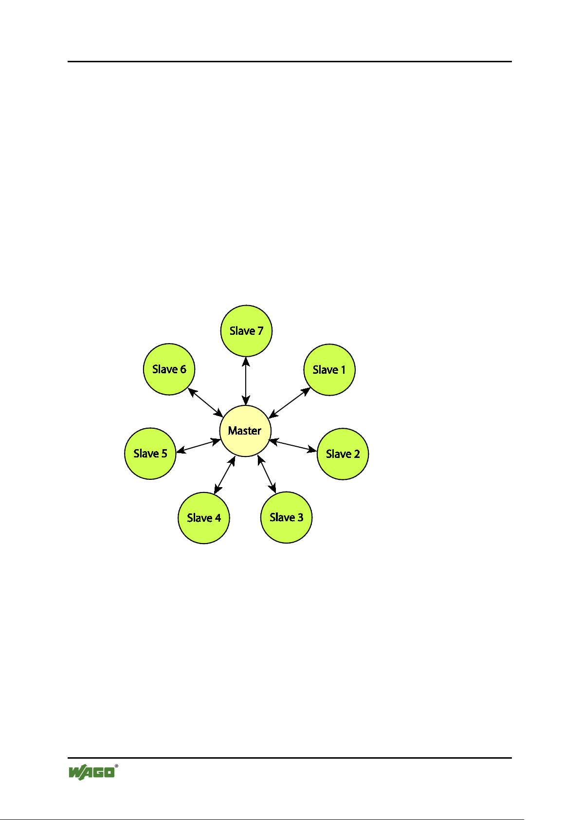
3.1 Piconet
Devices that use Bluetooth® technology to communicate form a so-called piconet.
One device assumes the master role and all others are slaves.
Figure 1: Piconet
Data is exchanged between the master and slave directly, but not between the
slaves themselves.
3.2 Profile and Identification
Bluetooth® technology can be used in many ways. Supported applications can
have very different requirements. For example, transmission of a business card or
audio signal requires different protocols. Bluetooth® devices normally support
only certain protocols. To make identification of suitable partners easier for
devices, profiles have been defined. Communication between devices is then
possible when both devices support the same profile.
Manual
Version 2.0.0, valid from FW/HW Version 03/03
Page 17

WAGO-I/O-SYSTEM 750 Bluetooth® Technology 17
Table 4: Classes (CoD) of WAGO devices
WAGO Device
CoD (hexadezimal)
Bluetooth® RF Transceiver 750-644
(real-time profile)
0x0020f8
Bluetooth® Module 757-801 with
RS-232
0x1f00
Bluetooth® Adapter 750-921
0x1f00
750-644 Bluetooth
®
RF-Transceiver
A standardized profile is the “Serial Port Profile” (SPP). It is used for wireless
transmission of serial interface data such as RS-232 or RS-485.
The “Service Discovery Profile” (SDP) supported by all Bluetooth® devices
allows a device to discover which devices are in range and to identify supported
profiles. Devices can broadcast which functions are supported by encoding such
functions as a so-called “Class of Device” (CoD) and by sharing that with other
devices. The CoD then makes it possible to look for devices with specific
functionality.
In addition to the CoD, all devices have a MAC ID that is used to uniquely
identify the device. Many devices also allow you to choose and save a specific
name for the device. This name is then also be queried wirelessly.
In addition to standardized profiles, industrial devices sometimes also use
proprietary profiles to meet specific requirements, e.g. in terms of reliability.
3.3 Security
Compatibility, connectivity and the security of radio communication are high
priorities for Bluetooth® technology. Due to the wide variety of devices and
applications that the technology uses, configurations can arise where devices are
unable to communicate with each other because of the different security
mechanisms implemented. This can affect devices, for example, that have no
configuration options for reasons of cost or devices that do not allow direct user
interaction based on their design.
3.4 Definition of Terms
The following table contains explanations about the terms used in this documentation.
Manual
Version 2.0.0, valid from FW/HW Version 03/03
Page 18

18 Bluetooth® Technology WAGO-I/O-SYSTEM 750
Table 5: Terms used
Term
Explanation
Local
A component or device to which there is a wired connection.
CHECK on the operator PC.
Remote
A component or device to which there is no wired connection.
Communication
partner
A remote device (from the perspective of the local device) or
the local device (from the perspective of a remote device).
In range
Devices or components are in range when transmitter and
settings are compatible.
Allowed
For secure connections, communication is only possible with
“authorized devices”, as well as “paired” or “coupled”.
Visible
Describes a Bluetooth® device that responds to scans from
come from authorized devices.
Connectable
Describes a Bluetooth® device to which connections can be
that number has already been reached.
Connected
Describes a state in which devices are able to exchange data
between authorized devices.
Authentication
Refers to the process of mutual verification of two Bluetooth®
not allowed.
750-644 Bluetooth
®
RF-Transceiver
Example: A 750-644 I/O module represented in WAGO-I/O-
receiver are mutually so strong or sensitive that
communication is technically possible. Whether
communication actually occurs depends on several other
factors, e.g. if radio connection is even wanted or if security
devices defined as “authorized devices”. Bluetooth®
technology designates devices that view each other as
Pos: 20 /Dokum entati on allg emei n/Gli ederung sele mente /---Seit enwe chs el--- @ 3\mod_1221108045078_0.docx @ 21810 @ @ 1
any other Bluetooth® device. A device that is not visible only
responds to scans or connection attempts when such attempts
established. Sometimes it may not be possible for authorized
devices to connect to a Bluetooth® device. This is the case,
for example, when the device is designed or configured to
allow only a certain number of simultaneous connections and
with each other. To do so, the devices must be in range. If the
devices have a secure connection, the connection must be
devices, where each device determines if the other is an
authorized device. Part of the process can be user interaction,
e.g. display of a dialog box on a smartphone or access to a
saved configuration that indicates which devices are and are
Manual
Version 2.0.0, valid from FW/HW Version 03/03
Page 19

WAGO-I/O-SYSTEM 750 Device Description 19
750-644 Bluetooth
Pos: 21 /All e S eri en ( Allg emei n e Mod ule) /Ü ber schri fte n f ür al le Ser ien/ Ger äte besc hrei bu ng/G erä te beschr ei bu ng - Ü bersc hrift 1 @ 3\mod_1233756084656_21.docx @ 27096 @ 1 @ 1
®
RF-Transceiver
4 Device Description
Pos: 22.1 /Serie 750 (WAGO-I/O-SYSTEM)/Gerätebeschreibung/Einleitung/Anwendung/SO/Anwendung 750- 0644 @ 15\mod_1365146295004_21.docx @ 116599 @ @ 1
The Bluetooth® RF Transceiver 750-644, hereafter referred to as the 750-644 I/O
module, is used to integrate a Bluetooth® network (Piconet) in the WAGO-I/OSYSTEM 750. 750-644 modules are installed and used jointly with other I/O
modules of the WAGO-I/O-SYSTEMs 750 in different fieldbus systems.
The 750-644 I/O module permits wireless exchange of data within the Bluetooth®
piconet. It can function as the coordinator (referred to in the following as the
“master”) or as the terminal (referred to in the following as the “slave”) depending
on the configuration. A maximum of seven slaves may communicate with one
master.
In piconets consisting of 750-644 I/O modules exclusively, the I/O modules can
use a specific proprietary profile for communication. If using the WAGO 758-912
antenna, ranges of up to 1000 meters can be achieved. In addition to particularly
robust, deterministic radio communication, expanded diagnostic functions are also
available.
The 750-644 I/O module can communication with devices from different
manufacturers that support the protocols of the SPP profile, i.e. the wireless
transmission of serial interface data. Apps are available that allow smartphones to
exchange data with the 750-644 I/O module.
The WAGO-I/O-CHECK software is used to configure the 750-644 I/O module
locally (network configuration, process image mapping). Eight 3-color LEDs
indicate the current status of the 750-644 I/O module.
Pos: 23 /Dokum entati on allg emei n/Gli ederung sele mente /---Seit enwe chs el--- @ 3\mod_1221108045078_0.docx @ 21810 @ @ 1
Pos: 24 /Ser ie 75 0 (WA GO-I/ O-SYS TEM )/ Ger äteb esc hrei bu ng/Ei nlei tu ng/E ins atz ber eich /Ei ns atzber ei ch 7 50- xxx x nur Koppl er/C ontrol ler a us Kompa tibili tätsli ste @ 4\ mod_1242389440265_21.docx @ 33262 @ @ 1
Pos: 25 /Ser ie 75 0 (WA GO-I/ O-SYS TEM )/ Gerät ebes chr eibu ng/Ei nlei tu ng/Ei ns atz berei ch/K om pati bilit ätsl isten /Kom patibi lität slist e 750-0644 @ 18\mod_1390827073962_21.docx @ 143418 @ @ 1
The 750-644 module can be used with the fieldbus couplers and controllers of the
WAGO-I/O-SYSTEM 750 of the specified version or higher listed in the
“Compatibility list” table.
Manual
Version 2.0.0, valid from FW/HW Version 03/03
Page 20

20 Device Description WAGO-I/O-SYSTEM 750
Table 6: Compatibility list
Bus system
Fieldbus couplers/controllers
Item no.
Hardware
status
Software
status
750 Series
BACnet/IP
Programmable fieldbus controller
750-830
03
03
Programmable fieldbus controller
750-831
01
01
CAL
Fieldbus coupler
750-305
CANopen
Fieldbus coupler
750-307
Programmable fieldbus controller
750-807
Fieldbus coupler
750-337
13
10
Fieldbus coupler, D-Sub
750-338
01
10
ECO fieldbus coupler
750-347
01
04
ECO fieldbus coupler, D-Sub
750-348
01
04
Programmable fieldbus controller,
MCS
750-837
06
11
Programmable fieldbus controller,
D-Sub
750-838
01
11
DeviceNet
Fieldbus coupler
750-306
15
4I
ECO fieldbus coupler
750-346
02
07
Programmable fieldbus controller
750-806
07
07
EtherCAT
Fieldbus coupler
750-354
01
01
ETHERNET
Programmable fieldbus controller
750-880
04
02
Programmable fieldbus controller,
TeleControl
750-880/
025-001
02
Programmable fieldbus controller,
TeleControl ECO
750-880/
025-002
02
Programmable fieldbus controller
750-881
02
03
Programmable media-redundant
fieldbus coupler
750-882
05
02
Programmable fieldbus controller,
Application Controller BA
750-884 02
Programmable media-redundant
fieldbus coupler
750-885
06
04
ETHERNET
TCP/IP fieldbus coupler
750-341
03
03
TCP/IP fieldbus coupler
750-342
04
14
Fieldbus coupler
750-352
02
02
Programmable fieldbus controller
750-841
11
07
Programmable fieldbus controller
750-842
13
12
Programmable fieldbus controller
750-843
Programmable fieldbus controller,
2 ports
750-871
05
07
Programmable fieldbus controller,
RS-232
750-873 03
IEC60870-5
Programmable fieldbus controller for
telecontrol applications
750-872
04
03
Programmable fieldbus controller for
telecontrol applications, TeleControl
750-872/
020-000
INTERBUS
Fieldbus coupler
750-304
Fieldbus coupler
750-324
Programmable fieldbus controller
750-804
Fieldbus coupler with fiber-optic
connection
750-334
ECO fieldbus coupler
750-344
ECO fieldbus coupler
750-345
750-644 Bluetooth
®
RF-Transceiver
TCP/IP
Manual
Version 2.0.0, valid from FW/HW Version 03/03
Page 21

WAGO-I/O-SYSTEM 750 Device Description 21
Table 6: Compatibility list
Bus system
Fieldbus couplers/controllers
Item no.
Hardware
status
Software
status
KNX IP
Programmable fieldbus controller
750-849
03
03
KNX IP
KNX IP controller
750-889
Linux®
Programmable fieldbus controller
750-860
Programmable fieldbus controller,
RS-232
750-863
LonWorks®
Fieldbus coupler
750-309
Programmable fieldbus controller
750-819
08
07
Fieldbus coupler
750-319
07
05
Peer-to-peer fieldbus coupler
750-319/
004-000
MODBUS
Fieldbus coupler, RS-485
750-312
Fieldbus coupler, RS-232
750-314
Fieldbus coupler, RS-485
750-315
Fieldbus coupler, RS-232
750-316
Programmable fieldbus controller,
RS-485
750-812
Programmable fieldbus controller,
RS-232
750-814
Programmable fieldbus controller,
RS-485
750-815
Programmable fieldbus controller,
RS-232
750-816
PROFIBUS
DP/FMS fieldbus coupler
750-303
01
07
Fieldbus coupler with fiber-optic
connection
750-331
DP/V1 fieldbus coupler
750-333
16
07
DPECO fieldbus coupler
750-343
03
06
DP fieldbus coupler
750-323
Programmable fieldbus controller
DP/V1
750-833
20
07
PROFINET IO
Fieldbus coupler
750-340
Fieldbus coupler, 2 ports
750-370
04
05
Fieldbus coupler, 2 ports
750-375
01
01
sercos III
Fieldbus coupler, 2 ports
750-351
02
02
758 Series
WAGO-I/O-IPC
758-870 06
750-644 Bluetooth
®
RF-Transceiver
Pos: 26 /Dokum entati on allg emei n/Gli ederung sele mente /---Seit enwe chs el--- @ 3\mod_1221108045078_0.docx @ 21810 @ @ 1
Manual
Version 2.0.0, valid from FW/HW Version 03/03
Page 22
22 Device Description WAGO-I/O-SYSTEM 750
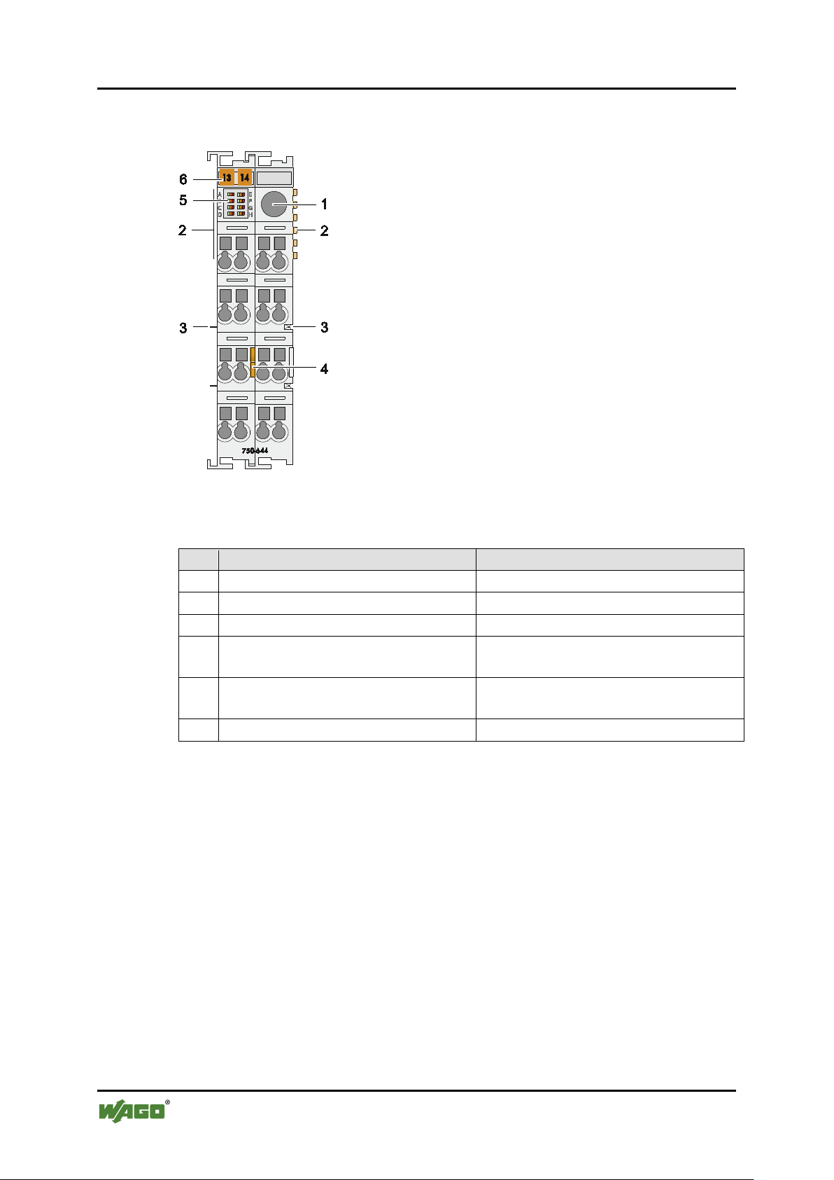
Table 7: Legend for the “View” figure
Pos.
Description
Details see section
1
Antenna socket SMA
“Device Description” > “Connectors”
2
Data contacts
“Device Description” > “Connectors”
3
Power jumper contacts
“Device Description” > “Connectors”
4
Release tab
“Mounting” > “Inserting and
Removing Devices”
5
Status LEDs
“Device Description” > “Display
Elements”
6
Marking possibility with Mini-WSB
---
750-644 Bluetooth
Pos: 27 /All e S eri en ( Allg emei n e Mod ule)/Ü ber schrif ten für al le Ser ien/G eräte besc hreibu ng/Ans icht - Ü ber schri ft 2 @ 4\ mod_1240984217343_21.doc x @ 31958 @ 2 @ 1
®
RF-Transceiver
4.1 View
Pos: 28 /Ser ie 75 0 (WA GO-I/ O-SYS TEM) /Ger ätebes chrei bung /Ansic ht/S onder klem men/A nsicht 750-0644 @ 15\mod_1365148663923_21.docx @ 116624 @ @ 1
Figure 2: View
Pos: 29 /D okum ent atio n al lge mein/ Gli eder ungs ele me nte/---Sei te nwec hsel--- @ 3\ mod_1221108045078_0.docx @ 21810 @ @ 1
Manual
Version 2.0.0, valid from FW/HW Version 03/03
Page 23
WAGO-I/O-SYSTEM 750 Device Description 23
750-644 Bluetooth
Pos: 30 /All e S eri en ( Allg emei n e Mod ule) /Ü ber schri fte n f ür al le Ser ien/ Ger äte besc hrei bu ng/A nsc hlü sse - Üb erschr ift 2 @ 4\mod_1240984262656_21.docx @ 31961 @ 2 @ 1
®
RF-Transceiver
4.2 Connectors
Pos: 31 /Ser ie 75 0 (WA GO-I/ O-SYS TEM )/ Gerät ebes chr eibu ng/A nsc hlüs se/D ate nko ntak te/Kl e mmen bus - Ü bersc hrift 3 @ 6\mod_1256294684083_21.docx @ 43660 @ 3 @ 1
4.2.1 Data Contacts/Internal Bus
Pos: 32.1 /Serie 750 (WAGO-I/O-S YST EM)/ Ger äteb esc hrei bung /Anschlüsse/Datenkontakte - Feldbuskoppler/-c ontr oll er, A bbi ldung u nd B esc hrei bu ng @ 3\mod_1231771259187_21.docx @ 26002 @ @ 1
Communication between the fieldbus coupler/controller and the I/O modules as
well as the system supply of the I/O modules is carried out via the internal bus. It
is comprised of 6 data contacts, which are available as self-cleaning gold spring
contacts.
Figure 3: Data contacts
Pos: 32.2 /Serie 750 (WAGO-I/O-S YSTEM )/Wi chtig e Erlä uteru ngen/ Sicher heits- und so nstig e H inw eis e/Ac htu ng/A ch tung : Bus kl em men nic ht a uf G oldf eder kon ta kte l eg en! @ 7 \mod_1266318463636_21.docx @ 50695 @ @ 1
Do not place the I/O modules on the gold spring contacts!
Do not place the I/O modules on the gold spring contacts in order to avoid soiling
or scratching!
Pos: 32.3 /Serie 750 (WAGO-I/O-S YSTEM )/Wi chtig e Erlä uteru ngen/ Sicher heits- und sonstige Hinweise/Achtung/Achtung: ESD - Auf gute Erdung der U mg ebu ng ac ht en! @ 7\ mod_1266318538667_21.docx @ 50708 @ @ 1
Ensure that the environment is well grounded!
The modules are equipped with electronic components that may be destroyed by
electrostatic discharge. When handling the modules, ensure that the environment
(persons, workplace and packing) is well grounded. Avoid touching conductive
components, e.g. data contacts.
Pos: 33 /Dokum entati on allg emei n/Gli ederung sele mente /---Seit enwe chs el--- @ 3\mod_1221108045078_0.docx @ 21810 @ @ 1
Manual
Version 2.0.0, valid from FW/HW Version 03/03
Page 24
24 Device Description WAGO-I/O-SYSTEM 750
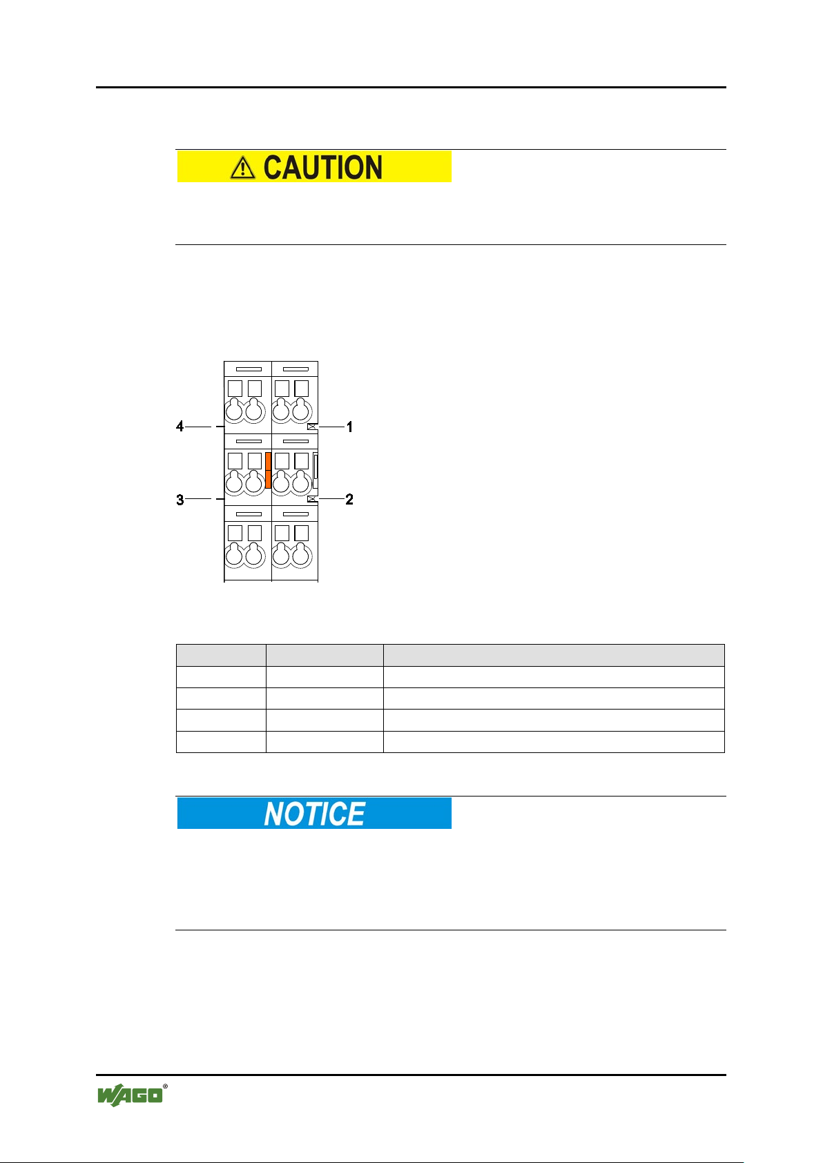
Table 8: Legend for the “Power jumper contacts” figure
Contact
Type
Function
1
Spring contact
Potential transmission (Uv) for field supply
2
Spring contact
Potential transmission (0 V) for field supply
3
Blade contact
Potential feed-in (0 V) for field supply
4
Blade contact
Potential feed-in (Uv) for field supply
750-644 Bluetooth
Pos: 34 /Ser ie 75 0 (WA GO-I/ O-S YSTEM )/ Ger äteb eschr ei bung/ Ansc hl üsse/ Leis tu ngs konta kte/F el dvers org ung - Über schr ift 3 @ 6\mod_1256294692864_21.docx @ 43664 @ 3 @ 1
®
RF-Transceiver
4.2.2 Power Jumper Contacts/Field Supply
Pos: 35.1 /Serie 750 (WAGO-I/O-S YSTEM )/Wi chtig e Erlä uteru ngen/ Sicher heits- und so nstig e H inw eis e/Vor sic ht/ Vor sic ht: Verl etz ungs ge fahr dur ch s ch arf kant ige M ess er kont akt e! @ 6\mod_1256193279401_21.docx @ 43414 @ @ 1
Risk of injury due to sharp-edged blade contacts!
The blade contacts are sharp-edged. Handle the I/O module carefully to prevent
injury.
Pos: 35.2 /Serie 750 (WAGO-I/O-S YST EM) /Ger äte bes chr ei bung /Ans chl üss e/L eist ung s konta kte 2 LK (M esser /Lei s tung sk onta kte 2 L K (Me sser /F ed er) - Einl eitung @ 15\mod_1371721641099_21.docx @ 123714 @ @ 1
The I/O module 750-644 has 2 self-cleaning power jumper contacts that supply
and transmit power for the field side. The contacts on the left side of the I/O
module are designed as blade contacts and those on the right side as spring
contacts.
Pos: 35.3 /S eri e 7 50 ( WA GO-I/O- SYST EM) /Ger äte bes chr ei bung /Ans chl üss e/L eist ung s konta kte 2 LK (M ess er/ Leis tung sk onta kte 2 L K (Me sser /F ed er) - Abbil du ng ( do ppelt e Br eit e) @ 15\ mod_1371721756578_21.docx @ 123718 @ @ 1
Figure 4: Power jumper contacts
Pos: 35.4 /Serie 750 (WAGO-I/O-SYSTEM)/Geräte bes chr ei bung /Ans chl üss e/L eist ung s konta kte 2 LK (M ess er/ Leis tung sk onta kte 2 L K (Me sser /F ed er) - Lege nde @ 15 \mod_1371721352500_21.doc x @ 123710 @ @ 1
Pos: 35.5 /Serie 750 (WAGO-I/O-S YSTEM )/Wi chtig e Erlä uteru ngen/ Sicher heits- und sonstig e Hinw eise/ Achtu ng/Ac htung : Maxi maler S trom Lei stung skon takte 10 A @ 3\mod_1226499143500_21.docx @ 25029 @ @ 1
Do not exceed maximum current via power contacts!
The maximum current to flow through the power contacts is 10 A.
Greater currents can damage the power contacts.
When configuring the system, ensure that this current is not exceeded. If
exceeded, an additional potential feed module must be used.
Pos: 35.6 /Serie 750 (WAGO-I/O-S YSTEM )/Wi chtig e Erlä uteru ngen/ Sicher heits- und sonstig e Hinw eise/H inwei s/Hi nweis : Potent ialei nspei sekl emme für Erde ei nsetz en! @ 3\mod_1226499037468_21.docx @ 25023 @ @ 1
Manual
Version 2.0.0, valid from FW/HW Version 03/03
Page 25

WAGO-I/O-SYSTEM 750 Device Description 25
750-644 Bluetooth
®
RF-Transceiver
Use potential feed module for Ground (earth)!
The I/O module has no power contacts for earth intake and transfer. Use a
potential feed module when an earth feed is needed for the subsequent I/O
modules.
Pos: 36 /Dokum entati on allg emei n/Gli ederung sele mente /---Seite nwe chsel --- @ 3\mod_1221108045078_0.docx @ 21810 @ @ 1
Manual
Version 2.0.0, valid from FW/HW Version 03/03
Page 26
26 Device Description WAGO-I/O-SYSTEM 750
750-644 Bluetooth
Pos: 37 /Ser ie 75 0 (WA GO-I/ O-SYS TEM )/ Gerät ebes chr eibu ng/A nsc hlüs se/A nte nne - Ü b ersc hrif t 2 @ 1 6\mod_1374051031775_21.docx @ 126410 @ 2 @ 1
®
RF-Transceiver
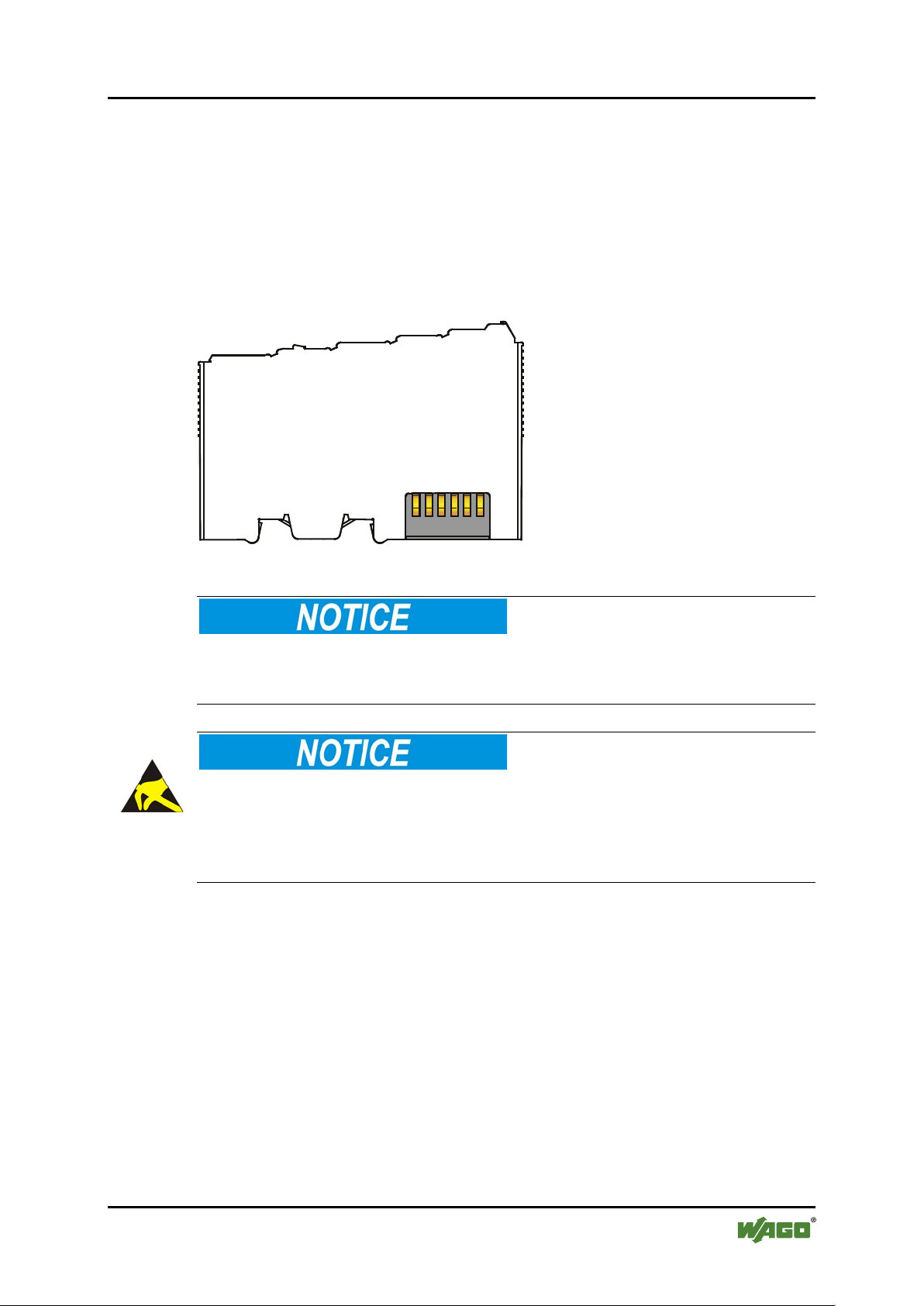
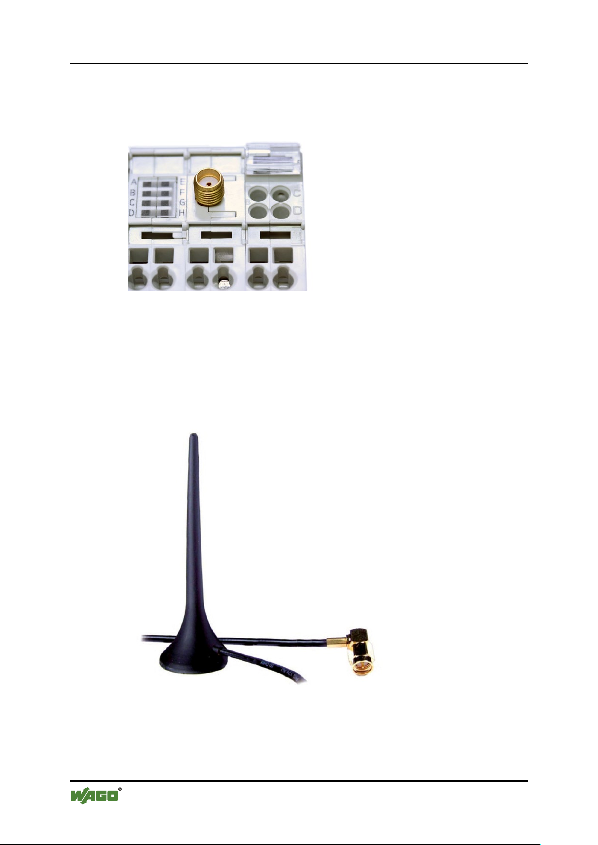
4.3 Antenna
Pos: 38 /Ser ie 75 0 (WA GO-I/ O-S YSTE M)/Z ub ehör /Zu beh ör f ür 750- 644 Antenne @ 16\mod_1376481596445_21.docx @ 128799 @ @ 1
The 750-644 I/O module has an SMA socket for attaching an external antenna.
Figure 5: SMA socket
The 750-644 I/O module can also be used without an external antenna, but the
achievable range of the radio connection is then significantly smaller.
In countries where use of radio products are regulated by the R&TTE directive,
any antenna with radio gain of 0 dBi or less can be used. For use in all other
countries where the I/O module can be operated, only the WAGO 758-912
magnetic base antenna can be used.
Figure 6: Accessory – WAGO 758-912 antenna
Manual
Version 2.0.0, valid from FW/HW Version 03/03
Page 27

WAGO-I/O-SYSTEM 750 Device Description 27
750-644 Bluetooth
®
RF-Transceiver
No operating license when antenna configuration is not approved!
Use of an unapproved antenna configuration can void your operating license. This
applies in particular when the equivalent isotropic radiated power (EIRP) of the
structure is higher when using the antenna configuration than is permitted
according to the regional or national specifications applicable to the location.
The composite function of the 750-644 I/O module and WAGO 758-912 antenna
is not intended for use outside of buildings.
Pos: 39 /Dokum entati on allg emei n/Gli ederung sele mente /---Seit enwe chs el--- @ 3\mod_1221108045078_0.docx @ 21810 @ @ 1
Manual
Version 2.0.0, valid from FW/HW Version 03/03
Page 28
28 Device Description WAGO-I/O-SYSTEM 750
Designation
LED
State
Function
green
I/O module ready for operation
red
I/O module note ready for operation
System is configured (in “Configuration”
nication” mode only).
off
I/O module note ready for operation
B, C,
G, H
Designation
LED
State
Function
Status
indicator
green
I/O module ready for operation
red
I/O module note ready for operation
off
Slave not connected
yellow
Wait for connection
yellow
flashing
green
Connection established
green
flashing
red
Connection error
750-644 Bluetooth
Pos: 40 /All e S eri en ( Allg emei n e Mod ule) /Ü ber schri fte n f ür al le Ser ien/ Ger äte besc hrei bu ng/A nz eig eele ment e - Über schri ft 2 @ 4\mod_1240984390875_21.docx @ 31964 @ 2 @ 1
®
RF-Transceiver
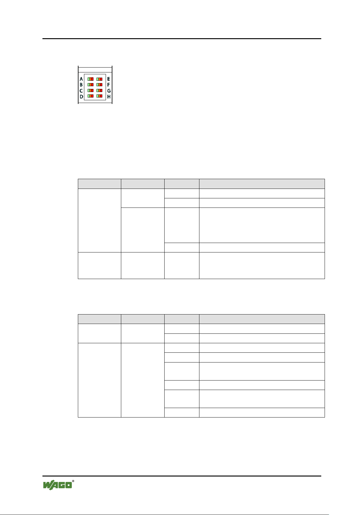
4.4 Display Elements
Pos: 41 /Ser ie 75 0 (WA GO-I/ O-SYS TEM) /Ger ätebes chrei bung /Anzei geel emen te/Son der klemm en/Anz eigeel ement e 750- 0644 @ 15\mod_1365149418098_21.docx @ 116650 @ 3333 @ 1
Figure 7: Display elements
8 LEDs indicate status. Depending on the operating mode
(configuration/communication) and role (master/slave), the LEDs display the
colors green, yellow or red as continuous illumination or flashing.
4.4.1 “Configuration” Mode
Table 9: Legend for the “Display elements” figure – “Configuration” mode
A
Status
indicator
E
-
D, F,
yellow
off -
mode only) or no connection to the first
slave could be established (in “Commu-
4.4.2 “Real-Time Communication” Mode, Master
Table 10: Legend for the “Display elements” figure – “Real-Time Communication” mode, master
A
Status of the
slave in slot
0x20, 0x21,
0x22, 0x23,
0x24, 0x25,
0x26
E, B, F, C,
G, D, H
Connection is being established
Data transfer
Manual
Version 2.0.0, valid from FW/HW Version 03/03
Page 29

WAGO-I/O-SYSTEM 750 Device Description 29
Designation
LED
State
Function
Status
indicator
green
I/O module ready for operation
red
I/O module note ready for operation
> 53 channels free (no or negligible
external activity in the frequency range)
yellow
39 … 53 uninterrupted channels
< 39 only marked as free (massive
external activity in the frequency range)
There is no connection or only for a few
seconds
green
Signal quality optimal
yellow
Signal quality moderate
red
Signal quality low
There is no connection or only for a few
seconds
green
Signal strength optimal
yellow
Signal strength high
red
Signal strength low
There is no connection or only for a few
seconds
off
Master not connected
yellow
Wait for connection
yellow
flashing
green
Connection established
green
flashing
red
Connection error
750-644 Bluetooth
®
RF-Transceiver
4.4.3 “Real-Time Communication” Mode, Slave
Table 11: Legend for the “Display elements” figure – “Real-Time Communication” mode, slave
A
green
Interference D, H
Signal
quality
Signal
strength
C, G
B, F
Status of the
master in
E
slow 0x20
red
off
off
off
Connection is being established
Data transfer
Manual
Version 2.0.0, valid from FW/HW Version 03/03
Page 30

30 Device Description WAGO-I/O-SYSTEM 750
Designation
LED
State
Function
Status
indicator
green
I/O module ready for operation
red
I/O module note ready for operation
off
No connection configured
yellow
Connection terminated
yellow
flashing
green
Connection established
green
flashing
red
Connection failed
red flashing
Connection terminated
flashing
green
- H off
-
750-644 Bluetooth
®
RF-Transceiver
4.4.4 “Ad-hoc Communication” Mode
Table 12: Legend for the “Display elements” figure – “Ad-hoc Communication” mode
A
Connection is being established
Status for
slot
0x10, 0x11,
0x12, 0x13,
0x14, 0x15
E, B, F, C,
G, D
Data transfer
Pos: 42 /Dokum entati on allg emei n/Gli ederung sele mente /---Seit enwe chs el--- @ 3\mod_1221108045078_0.docx @ 21810 @ @ 1
alternately
yellow and
Input buffer is full
Manual
Version 2.0.0, valid from FW/HW Version 03/03
Page 31

WAGO-I/O-SYSTEM 750 Device Description 31
750-644 Bluetooth
Pos: 43 /All e S eri en ( Allg emei n e Mod ule) /Ü ber schri fte n f ür al le Ser ien/ Ger äte besc hrei bu ng/Sc h ema tisch es Sch altbi l d - Ü bersc hri ft 2 @ 4\ mod_1240984441312_21.docx @ 31967 @ 2 @ 1
®
RF-Transceiver
4.5 Schematic Diagram
Pos: 44 /Ser ie 75 0 (WA GO-I/ O-SYS TEM )/ Gerät ebes chr ei bung /Sch ema tis che Sc halt bil der/ Son der kle mmen/ Sc hem atisc h es Sc halt bil d 7 50-0 644 @ 15 \mod_1365150212938_21.doc x @ 116653 @ @ 1
Figure 8: Schematic diagram
Pos: 45 /Dokum entati on allg emei n/Gli ederung sele mente /---Seit enwe chs el--- @ 3\mod_1221108045078_0.docx @ 21810 @ @ 1
Manual
Version 2.0.0, valid from FW/HW Version 03/03
Page 32

32 Device Description WAGO-I/O-SYSTEM 750
Table 13: Technical Data – Device
Width
24 mm
Height (from upper edge of DIN 35 rail)
64 mm
approx. 6.5 mm
Length
100 mm
Weight
85 g
Table 14: Technical Data – Supply
Bluetooth® power supply
via 24 V DC field supply
Current consumption, field supply
approx. 8 mA, max. 35 mA
Power supply, system
via system voltage (DC/DC)
Current consumption, system
approx. 20 mA
Isolation
500 V antenna/system
Table 15: Technical Data – Communication
Data width (internal)
Configurable to 12, 24, 48 bytes,
including 1 control/status byte
Wireless technology
Bluetooth® 2.0 + EDR
Frequency band
License-free ISM band, 2402-2480
MHz
Transmitter power
up to 20 dBm (Bluetooth® Class 1)
Receiver sensitivity
-94 dBm
Transmission range
Max. 1000 m open area, 100 m in
WAGO, item no. 758-912)
Topology
Piconet (1 master, max. 7 slaves)
Coexistence
AFH and adaptive transmission power
Profile, standard
Serial Port Profile (SPP)
Profile, proprietary
Real-time
750-644 Bluetooth
Pos: 46 /All e S eri en ( Allg emei n e Mod ule) /Ü ber schri fte n f ür al le Serien/Gerätebeschreibung/Technische Daten - Üb ersc hrif t 2 @ 3 \mod_1232967587687_21.docx @ 26924 @ 2 @ 1
®
RF-Transceiver
4.6 Technical Data
Pos: 47 /Ser ie 75 0 (WA GO-I/ O-SYS TEM )/ Ger äteb esc hrei bu ng/T ech nisc he D ate n/ Son derkl e mmen/T ec hni sch e D ate n 75 0-064 4 @ 15\mod_1365150321151_21.docx @ 116656 @ 3333 @ 1
4.6.1 Device
+ excess length of the SMA socket
4.6.2 Supply
4.6.3 Communication
building
(using the magnetic base antenna from
Manual
Version 2.0.0, valid from FW/HW Version 03/03
Page 33

WAGO-I/O-SYSTEM 750 Device Description 33
Table 16: Technical Data – Configuration and Diagnostics
Diagnostics, statuses
Device status, connection status, signal
strength, signal quality, interference
Diagnostics, interfaces
LED indication, process image,
WAGO-I/O-CHECK
Configuration
WAGO-I/O-CHECK, WAGO-I/O-PRO
CAA
Table 17: Technical data – Climatic environmental conditions
Operating temperature range
0 °C … 55 °C
Storage temperature range
-25 °C … +85 °C
Relative humidity without condensation
max. 95 %
Resistance to harmful substances
Acc. to IEC 60068-2-42 and
IEC 60068-2-43
Maximum pollutant concentration at
SO2 ≤ 25 ppm
H2S ≤ 10 ppm
Special conditions
Ensure that additional measures for
– ionizing radiation
Table 18: Technical Data – Field Wiring
Wire connection
CAGE CLAMP®
Cross section
0.08 mm² … 2.5 mm², AWG 28 … 14
Stripped lengths
8 mm … 9 mm / 0.33 in
Table 19: Technical Data – Power Jumper Contacts
Power jumper contacts
blade/spring contact, self-cleaning
Voltage drop at I
max.
< 1 V/64 modules
Table 20: Technical Data – Internal Bus
Data contacts
slide contact, hard gold plated, selfcleaning
750-644 Bluetooth
®
RF-Transceiver
4.6.4 Configuration and Diagnostics
Pos: 48 /Ser ie 75 0 (WA GO-I/ O-S YSTE M)/ Ger ät ebesc hrei bu ng/T ech nisc h e Dat en/ Kli mati sch e U mwel tbe ding ung en /Tec hnis che Da ten Kli matis ch e U mwel tbe ding ung en o. er w. Tem pber ei ch; 0.. .55°C /-25 ...+85°C @ 5\mod_1247657968368_21.docx @ 37603 @ 3 @ 1
4.6.5 Climatic Environmental Conditions
relative humidity < 75 %
Pos: 49.1 /Al l e Ser ien ( Al lge mei ne M od ule)/Ü ber sc hrift e n für all e S eri en/G erä teb esc hreib ung /A nsc hlus stec hni k - Ü ber schri ft 3 @ 17\mod_1380123271324_21.docx @ 132788 @ 3 @ 1
4.6.6 Connection Type
Pos: 49.2 /Serie 750 ( WAGO- I/O-S YST EM)/ Ger äte besc hrei bu ng/T ech nis che Da ten/T ec hni sch e Dat e n Verdr ah tung s eben e CC - 0,08 bis 2,5mm2 @ 17\mod_1380121238809_21.docx @ 132780 @ @ 1
Pos: 49.3 /Serie 750 (WAGO-I/O-S YST EM) /Ger äte bes chr ei bung /T echni sc he Da ten/ A nsc hluss tec hni k/T echni sc he D at en L eist ungs ko nta kte ( Mes ser/ Fe der) @ 17\ mod_1380123464149_21.docx @ 132791 @ @ 1
Pos: 49.4 /Serie 750 (WAGO-I/O-S YST EM)/ Ger äteb esc hrei bung /T echni sche Da ten/ Ans chl uss tech ni k/Tec hnis ch e D aten Kl emme nbus @ 17\ mod_1380123495844_21.docx @ 132794 @ @ 1
components are taken, which are used in
an environment involving:
– dust, caustic vapors or gases
Pos: 50 /D okum ent atio n al lge mein/ Gli eder ungs ele me nte/---Sei te nwec hsel--- @ 3\ mod_1221108045078_0.docx @ 21810 @ @ 1
Manual
Version 2.0.0, valid from FW/HW Version 03/03
Page 34

34 Device Description WAGO-I/O-SYSTEM 750
Conformity Marking
This device complies with Part 15 of the FCC Rules. Operation is subject to the following two conditions:
received, including interference that may cause undesired operation.
Bluetooth®
TÜV 07 ATEX 554086 X
I M2 Ex d I Mb
II 3 D Ex tc IIIC T135°C Dc
Ambient temperature range:
0 °C ≤ Ta ≤ +60 °C
IECEx TUN 09.0001 X
Ex d I Mb
Ex tc IIIC T135°C Dc
Ambient temperature range:
0 °C ≤ Ta ≤ +60 °C
750-644 Bluetooth
Pos: 51 /All e S eri en ( Allg emei n e Mod ule) /Ü ber schri fte n f ür al le Ser ien/ Ger äte besc hrei bu ng/Z ul assu ngen - Üb ersc hrift 2 @ 3\ mod_1224055364109_21.docx @ 24030 @ 2 @ 1
®
RF-Transceiver
4.7 Approvals
Pos: 52 /Ser ie 75 0 (WA GO-I/ O-SYS TEM )/ Ger äteb esc hrei bu ng/Z ulass u nge n/Al lg emei n/Z ulass ung en B us kle mme 75 0-xx xx Allge mein, ohne Var iant enang abe - Einl eitung @ 4\mod_1237460656921_21.docx @ 28643 @ @ 1
The following approvals have been granted to 750-644 I/O modules:
Pos: 53 /All e S eri en ( Allg emei n e Mod ule) /Z ulas sung en/ St and ardz ula ssu nge n/cU Lus ( U L50 8) @ 3\mod_1224055013140_0.docx @ 24020 @ @ 1
Pos: 54 /All e S eri en ( Allg emei n e Module)/Zulassungen/Standardzulassungen/C E (Konformitätskennzeichnung) @ 3\ mod_1224494777421_21.docx @ 24276 @ @ 1
Pos: 55 /All e S eri en ( Allg emei n e Mod ule) /Z ulas sung en/ St and ardz ula ssu nge n/FCC ( Feder al Co mmu nica tio ns C om missi on) - FCC ID: PV7-WT B08 @ 5\mod_1250676362421_21.docx @ 40821 @ @ 1
Pos: 56 /All e S eri en ( Allg emei n e Mod ule) /Z ulas sung en/ St and ardz ula ssu nge n/Bl uetooth @ 5\mod_1250677059984_21.docx @ 40825 @ @ 1
Pos: 57 /All e S eri en ( Allg emei n e Mod ule) /Z ulas sung en/ Sc hiffs zul ass ung en/ BSH (B und esam t für Se esc hiff fahr t u nd H ydr ogr aphi e) @ 5\ mod_1246341825156_21.docx @ 36334 @ @ 1
Pos: 58 /All e S eri en ( Allg emei n e Mod ule) /Z ulas sung en/ St and ardz ula ssu nge n/NCC @ 15\ mod_1366900608399_21.docx @ 118043 @ @ 1
本產品符合低功率電波輻射性電機管理辦法 第十二條、第十四條等條文規定
1. 經型式認證合格之低功率射頻電機,非經許可,公司、商號或使用者均不得擅
2. 低功率射頻電機之使用不得影響飛航安全及干擾合法通信;經發現有干擾現象
前項合法通信,指依電信法規定作業之無線電通信。
低功率射頻電機須忍受合法通信或工業、科學及醫療用電波輻射性電機設備之
Pos: 59 /Ser ie 75 0 (WA GO-I/ O-SYS TEM) /Ger ätebes chrei bung /Zulass ung en/E x/Zulas sung en Bus klem me 750- xxxx Ex, ohne Variantenangabe - Einl eit ung @ 4\ mod_1237191218000_21.docx @ 28423 @ @ 1
The following Ex approvals have been granted to 750-644 I/O modules:
Pos: 60.1 /Al l e Ser ien ( Al lge mei ne M od ule)/Z ul assu nge n/ Ex-Zul ass u ngen /TÜV AT EX/T Ü V 07 ATE X 5 540 86 X: I M 2 E x d I M b II 3 G E x n A IIC T 4 Gc I I 3 D E x tc I IIC T1 35°C D c @ 14\mod_1361949753233_0.docx @ 113015 @ @ 1
CULUS
UL508
FCC “Federal Communications Commission” FCC ID: PV7-WTB08
(1) this device may not cause harmful interference, and (2) this device must accept any interference
Federal Maritime and Hydrographic Agency
NCC CCAB12LP1280T4
自變更頻率、加大功率或變更原設計之特性及功能。
時,應立即停用,並改善至無干擾時方得繼續使用。
干擾。
II 3 G Ex nA IIC T4 Gc
Pos: 60.2 /Al l e Ser ien ( Al lge mei ne M od ule)/Z ul assu nge n/ Ex-Zul ass u ngen /Erg änz ung Z ul ässi ger U mgeb ungs te mper at urb ereic h 0 ° C < = T a <= +6 0 °C @ 9 \mod_1295605895541_21.docx @ 68610 @ @ 1
Pos: 60.3 /Al l e Ser ien ( Al lge mei ne M od ule)/Z ul assu nge n/ Ex-Zul ass u ngen /IEC Ex (TÜ V Nor d) /IEC Ex TUN 09 .000 1 X: Ex d I M b E x nA IIC T4 Gc Ex tc IIIC T 135°C @ 14\ mod_1361950034299_0.docx @ 113019 @ @ 1
Ex nA IIC T4 Gc
Pos: 60.4 /Al l e Ser ien ( Al lge mei ne M od ule)/Z ul assu nge n/ Ex-Zul ass u ngen /Erg änz ung Z ul ässi ger U mgeb ungs te mper at urb ereic h 0 ° C < = T a <= +6 0 °C @ 9 \mod_1295605895541_21.docx @ 68610 @ @ 1
Pos: 60.5 /Al l e Ser ien ( Al lge mei ne M od ule)/Z ul assu nge n/ Ex-Zul ass u ngen /cU Lus /cU Lus ( AN SI/I SA 12.1 2.01) Cl ass I, Div2 ABCD T4 @ 3\ mod_1224054791812_0.docx @ 24014 @ @ 1
Manual
Version 2.0.0, valid from FW/HW Version 03/03
Page 35

WAGO-I/O-SYSTEM 750 Device Description 35
CULUS
ANSI/ISA 12.12.01
Class I, Div2 ABCD T4
750-644 Bluetooth
®
RF-Transceiver
Pos: 60.6 /Dokumentation allgemein/Glieder ungselemente/------Leerzeile------ @ 3\mod_1224662755687_0.docx @ 24460 @ @ 1
Pos: 61 /Alle Seri en (Al lge mei ne Mo dul e)/Ü b erschr if ten f ür all e S erie n/G erä teb esc hreib ung /Nor m en u nd Ri cht lini en - Über schr ift 2 @ 4\mod_1242804031875_21.docx @ 33646 @ 2 @ 1
4.8 Standards and Guidelines
Pos: 62 /Ser ie 75 0 (WA GO-I/ O-SYS TEM )/ Ger äteb esc hrei bu ng/N orm en u nd R ic htlini e n/EM V-Nor men B uskl em me 7 50-xx xx, ohn e Vari anten angab e - Einlei tung @ 4\mod_1242803944015_21.docx @ 33642 @ @ 1
750-644 I/O modules meet the following requirements on emission and immunity
of interference:
Pos: 63 /Alle Seri en (Al lge mei ne Mo dul e)/N or men und R ic htli nie n/ EMV-N orm en - Stan dar d/EM V CE -Stör fes tigkei t EN 610 00-6-2: 2005 @ 4\mod_1242797655625_21.docx @ 33591 @ @ 1
EMC CE-Immunity to interference acc. to EN 61000-6-2: 2005
Pos: 64 /All e S eri en ( Allg emei n e Mod ule) /N or men un d Ri chtl i nien/ EM V-N orme n - St andar d/ EMV CE- Stör festi gkeit EN 6113 1-2: 2007 @ 6\mod_1259753054539_21.docx @ 46414 @ @ 1
EMC CE-Immunity to interference acc. to EN 61131-2: 2007
Pos: 65 /All e S eri en ( Allg emei n e Mod ule) /N or men un d Ri chtl i nien/ EM V-N orme n - St andar d/ EMV CE- Störaussendung EN 61000-6-3: 2007 @ 4\mod_1242798094468_21.docx @ 33598 @ @ 1
EMC CE-Emission of interference acc. to EN 61000-6-3: 2007
Pos: 66 /All e S eri en ( Allg emei n e Mod ule) /N or men un d Ri chtl i nien/ EM V-N orme n - St andar d/ EMV CE- Störaussendung EN 61131-2: 2007 @ 6\mod_1259753022195_21.docx @ 46410 @ @ 1
EMC CE-Emission of interference acc. to EN 61131-2: 2003
Pos: 67 /Dokum entati on allg emei n/Gli ederung sele mente /---Seit enwe chs el--- @ 3\mod_1221108045078_0.docx @ 21810 @ @ 1
Manual
Version 2.0.0, valid from FW/HW Version 03/03
Page 36

36 Function Description WAGO-I/O-SYSTEM 750
750-644 Bluetooth
Pos: 68.1 /Al l e Ser ien ( Al lge mei ne M od ule)/Ü ber sc hrift e n für all e S eri en/F unk tio nsbes chr eib ung - Üb ersc hrif t 1 @ 4 \mod_1239025975389_21.docx @ 30003 @ 1 @ 1
®
RF-Transceiver
5 Function Description
Pos: 68.2 /Serie 750 (WAGO-I/O-SYSTEM)/Funktionsbeschreibung/Funktionsbeschreibung 750-0644 - Einleitung @ 16\mod_1376486304025_21.docx @ 128807 @ @ 1
The 750-644 I/O module allows wireless communication with other Bluetooth®
devices.
Depending on the operating mode, data can be exchanged with up to 7 other
750-644 I/O modules or 6 Bluetooth® SPP devices.
Figure 9: Device classification: Local/remote, authorized/not authorized, connected/not connected,
in range/out of range
Pos: 68.3 /Serie 750 (WAGO-I/O-S YSTEM )/F unktio nsbes chrei bung /Fun ktionsb eschr eibu ng 750-0644 - Betr ie bsar ten @ 16\mod_1376486140756_21.docx @ 128803 @ 2333 @ 1
5.1 Operating Modes
The 750-644 I/O module has 3 different operating modes.
The operating mode is changed using WAGO-I/O-CHECK or function blocks in
the WAGO-I/O-PRO CAA software and is controlled by mailbox commands. The
Bluetooth® subsystem is automatically reset after changing the operating mode.
When used for the first time, the 750-644 I/O module is automatically operated in
“Configuration” mode. If the “Real-Time Communication” or “Ad-hoc Communication” mode has already been selected in WAGO-I/O-CHECK, the 750-644
I/O module is transferred to the respective profile. During startup of the 750-644
I/O module, the last configuration made is loaded.
Manual
Version 2.0.0, valid from FW/HW Version 03/03
Page 37

WAGO-I/O-SYSTEM 750 Function Description 37
750-644 Bluetooth
®
RF-Transceiver
5.1.1 “Configuration” Mode
In “Configuration” mode, all parameters of the 750-644 I/O module are
configured, e.g. via WAGO-I/O-CHECK or function blocks of WAGO-I/O-PRO
CAA. Alternatively, the I/O module can also be configured via the process image
directly. The Mailbox protocol is used for this purpose. A description of all
Mailbox commands is available in the appendix under “Mailbox Commands”.
Of particular importance is configuration of the settings that define with which
remote 750-644 I/O modules or remote Bluetooth® SPP devices a radio
connection should be set up. These settings are summarized under the term “Net
Forming” (see section “Function Description” > … > “Net Forming”).
In “Configuration” mode, no data connection is established with remote 750-644
I/O modules or remote Bluetooth® SPP devices. All process data assigned to the
respective slots have the content “0”. However, a Bluetooth® inquiry can be used
to scan for remote 750-644 I/O modules or remote Bluetooth® SPP devices and a
query to identify the MAC ID and device name.
5.1.2 “Real-Time Communication” Mode
In “Real-Time Communication” mode, the 750-644 I/O module uses a proprietary
real-time profile for radio communication. Operation in this mode has the
following characteristics:
• Automatic connection to and communication with up to 7 other 750-644 I/O
modules
• Cyclical transmission of assigned information of the output process image
(PIO)
• Long ranges are possible
• Deterministic latency and cycle time
• Monitoring the timing using software watchdog
5.1.3 “Ad-hoc Communication” Mode
In “Ad-hoc Communication” mode, the 750-644 I/O module uses the standardized
“Serial Port Profile” (SPP) for radio communication with remote Bluetooth® SPP
devices. Operation in this mode has the following characteristics:
• Manual connection to and communication with up to 6 remote Bluetooth®
SPP devices
• Serial transmission of information
• Flow control by handshake bytes (HS bytes)
• Range is determined in each case by the weakest device
Pos: 68.4 /Serie 750 (WAGO-I/O-S YST EM)/ Fun ktio nsbe schr eib ung /Fu nktion sbesc hrei bung 75 0-0644 - Funksc hnitts tell e/Net F orming @ 16\mod_1376487092128_21.docx @ 128851 @ 2344 @ 1
5.2 Radio Interface
The 750-644 I/O module permits wireless exchange of data with remote devices
using version 2.0 of the Bluetooth® standard.
The following profiles are supported for communication:
Manual
Version 2.0.0, valid from FW/HW Version 03/03
Page 38

38 Function Description WAGO-I/O-SYSTEM 750
Table 21: Net Forming, assignment of the slot addresses
Mode
Role
Description
Connection with up to 7 other 750-644 I/O modules
are each configured as a slave
Connection with 1 other 750-644 I/O module whose
master
Connection with up to 6 other Bluetooth® SPP devices
each taking the role of a slave
Connection with up to 6 other Bluetooth® SPP devices
their role is arbitrary
750-644 Bluetooth
®
RF-Transceiver
• “Serial Port Profile” (SPP) for communication with devices of other
manufacturers. This profile is used in “Ad-hoc Communication” mode.
• Real-time profile for communication with other 750-644 I/O modules.
This profile is used in “Real-Time Communication” mode.
5.2.1 Net Forming
5.2.1.1 Slots, Slot Addresses
To establish a Bluetooth® connection to another device, its MAC ID must be
known. The MAC ID is used for unique identification of the respective
connection partner.
The respective MAC ID and other connection settings can be saved in the
750-644 I/O module for up to 13 possible connection partners. The connection
settings are referred to as “slots” below. The possible connection partners
identified by MAC IDs are referred to as “authorized devices” below. For each
slot, one so-called UserFriendlyName can also be assigned that, for example,
identifies the function of the device.
Depending on the operating mode and role of the master or slave, connections
can be maintained for up to seven slots. The slots for the “Real-Time Communication” mode are managed using slot addresses 0x20 … 0x26 and the slots for
“Ad-hoc Communication” using slot addresses 0x10 … 0x15.
Use is described in the following table:
Real-Time
Master
whose MAC IDs are saved as slots 0x20 … 0x26 and
Communication
Ad-hoc
Slave
Master
MAC ID is saved as slot 0x20 and is configured as a
whose MAC IDs are saved as slots 0x10 … 0x15 and
Communication
Slave
whose MAC IDs are saved as slots 0x10 … 0x15 and
5.2.1.2 Scan for Remote Devices
An inquiry can be used to determine the MAC ID of a Bluetooth® device if
unknown. This requires that the target device is within range and that it responds
to scans, i.e. it is “visible”.
Manual
Version 2.0.0, valid from FW/HW Version 03/03
Page 39

WAGO-I/O-SYSTEM 750 Function Description 39
750-644 Bluetooth
®
RF-Transceiver
The result of a device scan is usually a list with the MAC IDs with the Bluetooth®
found. In addition to the MAC IDs, the 750-644 I/O module also makes it possible
to determine the names of the Bluetooth® devices found.
The Bluetooth® device names can help to identify specific devices.
Bluetooth® devices can take very different functions and a scan may find
numerous devices or even devices with which communication is not possible. To
prevent this, the “Class of Device” (CoD) can be used to limit the scan.
The 750-644 I/O module makes it possible to scan for Bluetooth® devices of a
specific CoD explicitly. In this way, for example, the scan is limited to other
750-644 I/O modules.
Pos: 68.5 /Serie 750 (WAGO-I/O-S YSTEM )/F unktio nsbes chrei bung /Fun ktionsb eschr eibu ng 750-0644 - Fu nksc hni ttst ell e/Be tri ebs art Echtz eit @ 16\ mod_1376487921762_21.docx @ 128855 @ 33 @ 1
5.2.2 Operation as a Master in “Real-Time Communication” Mode
When operated as a master in “Real-Time Communication” mode, the 750-644
I/O module plays the role of a master in the Bluetooth® piconet. In this operating
mode, the 750-644 I/O module is not visible, i.e. it does not respond to scans.
After power-on or restart in this operating mode, the 750-644 I/O module
automatically attempts to establish a connection to all slots for which the
following applies:
• Slot address falls in the range 0x20 … 0x26 (real-time slots)
• The MAC ID configured for the slot does not equal 0
• The slot has been enabled for connection
The 750-644 I/O module configured as a master establishes connections in order
of the slot addresses. If the other 750-644 I/O modules to be connected as slaves
are ready to connect, the following approximate times apply for establishing a
connection:
• Approx. 5 s to establish a connection to the first slot activated
• Approx. 3 s to establish a connection to any other slot activated
If a remote 750-644 I/O module configured for a slot does not connect after
approx. 5 seconds, e.g. because it is out of range, the local 750-644 I/O module
continues with the next slot to be connected until the slots activated to be
connected have been scanned once to establish the connection.
If the connection to one or more other 750-644 I/O modules could not be
established or was interrupted later, the 750-644 I/O module attempts to
reestablish a connection at regular intervals.
The interval between two attempts to establish all activated, but not yet existing
connections can be configured.
Manual
Version 2.0.0, valid from FW/HW Version 03/03
Page 40

40 Function Description WAGO-I/O-SYSTEM 750
750-644 Bluetooth
®
RF-Transceiver
No data exchange when establishing a connection!
While the 750-644 I/O module establishes radio connections, any existing radio
connections are paused. Cyclic data exchange is interrupted for all slots already
connected.
Connections to failed devices can be temporarily deactivated!
Repeated attempts to reestablish failed connections may affect data exchange for
intact connections. To avoid this, individual slots can be temporarily excluded
when making a connection. For this purpose, the respective connection can be
marked as “not activated for connection” in “Real-Time Communication” mode.
This setting is stored in volatile memory and remains valid until the next restart.
Until then, the 750-644 I/O module excludes the connection concerned from
automatic connection establishment.
If all slots activated for the connection are connected, or if the wait time for
another connection attempt has not elapsed, the 750-644 I/O module exchanges
data cyclically with all connected remote 750-644 I/O modules. The timing is
monitored. If a connected slot receives no data, a warning and then error is
indicated. If a connection is completely interrupted by a remote I/O module, a
general error is indicated. The process data of the respective slot then remains
unchanged until reconnected or new data has been received. More information is
available in the sections “Process Image” and “Diagnostics”.
5.2.3 Operation as a Slave in “Real-Time Communication” Mode
When operated as a slave in “Real-Time Communication” mode, the 750-644 I/O
module plays the role of a slave in the Bluetooth® piconet. In this operating mode,
the 750-644 I/O module is not visible, i.e. it does not respond to scans. After
power-on, restart in this mode or the connection is interrupted, the I/O module
waits continuously until establishment or reestablishment of the connection by the
assigned master. The assigned master is the device assigned to slot address 0x20.
Once the 750-644 I/O module configured as the master has established the
connection, both I/O modules exchange data cyclically. Monitoring the
connection status and timing is basically identical for master and slave in “RealTime Communication” mode where only the connection to the master is
monitored when operated as a slave.
Pos: 68.6 /Serie 750 ( WAGO- I/O-S YSTEM )/Fun ktions besc hreib ung/ Funkti onsb eschr eibung 750-0644 - Fun ksch nitts tel le/ Be trieb sar t A d-Hoc @ 16\ mod_1376489089215_21.docx @ 128889 @ 33 @ 1
5.2.4 Operation as a Master in “Ad-hoc Communication” Mode
When operated as a master in “Ad-hoc Communication” mode, the 750-644 I/O
module can only be connected to Bluetooth® SPP devices that in turn take the role
of a slave.
In this operating mode, the I/O module can maintain up to 6 connections. The
following conditions apply:
Manual
Version 2.0.0, valid from FW/HW Version 03/03
Page 41

WAGO-I/O-SYSTEM 750 Function Description 41
750-644 Bluetooth
®
RF-Transceiver
• The MAC ID of the device to be connected is entered for one of the ad-hoc
slots (0x10 … 0x15).
• The slot has been enabled for the connection.
The connection is not established automatically in this operating mode, i.e. if the
local 750-644 I/O module should establish a connection, the process must be
initiated by a corresponding parameter in the process image (see section “Process
Image”). In this operating mode, connections can also be established externally. If
the above conditions are met, the 750-644 I/O module automatically accepts a
connection established externally.
5.2.5 Operation as a Slave in “Ad-hoc Communication” Mode
When operated as a slave in “Ad-hoc Communication” mode, the 750-644 I/O
module can be connected to other Bluetooth® SPP devices irrespective of whether
they assume the role of a master or slave.
The number of supported connections, the requirements for the configuration and
the procedures for establishing a connection are identical when operated as a
master.
Lower power when operating in a scatternet!
If the 750-644 I/O module is operated as a slave in “Ad-hoc Communication”
mode and it maintains more than one connection, the resulting Bluetooth®
network may not have a piconet topology, but a scatternet topology. If so,
significantly worse timing must be expected.
Pos: 68.7 /Serie 750 (WAGO-I/O-S YSTEM )/F unktio nsbes chrei bung /Fun ktionsb eschr eibu ng 750-0644 - Fu nksc hni ttst ell e/Ver bi ndb ar keit und Vers chl üss elu ng @ 16\ mod_1376489333142_21.docx @ 128893 @ 3333 @ 1
5.2.6 Visibility and Connectivity
Whether the 750-644 I/O module responds to a device scan of remote Bluetooth®
devices or not depends on the set operating mode. If yes, it is “visible”.
The 750-644 I/O module is visible under the following conditions:
• “Ad-hoc Communication” mode or
• “Configuration” mode
A connection between the 750-644 I/O module and a remote Bluetooth® device is
generally only possible if the configuration of the I/O module defines it as an
authorized device.
• “Real-Time Communication” mode:
The MAC ID of the remote device is entered for one of the slot addresses
0x20 … 0x26. The related slot is activated for the connection.
• “Ad-hoc Communication” mode:
The MAC ID of the remote device is entered for one of the slot addresses
0x10 … 0x15. The related slot is activated for the connection.
Manual
Version 2.0.0, valid from FW/HW Version 03/03
Page 42

42 Function Description WAGO-I/O-SYSTEM 750
750-644 Bluetooth
®
RF-Transceiver
Regardless of the operating mode, a connection is only possible when the security
settings of the I/O module and those of the remote Bluetooth® device are
compatible.
Use authentication and encryption for compatibility!
Many Bluetooth® devices are set up to only allow secure connections. To achieve
maximum compatibility, the I/O module should in turn be set to force authentication and encryption.
5.2.7 Encryption
The 750-644 I/O module supports both encrypted and unencrypted connections.
5.2.8 Authentication
The 750-644 I/O module supports connections with informal or no authentication
or with secure authentication.
5.2.9 Coexistence
The 750-644 I/O module allows coexistence of other wireless networks through
adaptive frequency hopping (AFH) according to the Bluetooth® standard. AFH
automatically detects occupied frequency ranges of other wireless networks. The
detected frequency ranges are automatically avoided by the 750-644 I/O module.
The 750-644 I/O module reads the avoided frequency ranges in the form of a
channel blacklist, i.e. a list that includes the 79 possible channels currently
excluded from its own transmissions. Based on the channel blacklist, it is also
possible to draw conclusions about other wireless networks or interference in the
frequency band.
The 750-644 I/O module supports automatic adjustment of the transmission power
according to the Bluetooth® standard. If a remote devices tells the I/O module that
the received signal strength is higher than needed, the I/O module automatically
reduces its transmission power. Likewise, the 750-644 I/O module automatically
increases its transmission power if a remote device tells the I/O module that the
received signal strength is too low.
The configuration of the 750-644 I/O module allows the user to set upper limits
for automatic adjustment of the transmission power. The lower the transmission
power, the smaller the distance at which other Bluetooth® devices can receive
data. Adjusting the transmission power can be used to increase security or to
improve transmission quality in other wireless networks.
Two upper limits can be defined:
• Default transmission power:
This value determines which transmission power the I/O module uses for a
device scan or when establishing a connection or shortly after establishing a
Manual
Version 2.0.0, valid from FW/HW Version 03/03
Page 43

WAGO-I/O-SYSTEM 750 Function Description 43
Table 22: Factory settings of the 750-644 I/O module
Parameters
Settings
Bluetooth® device name
WAGO-750-644
Default transmission power
20 dBm
Maximum transmission power
20 dBm
Device role
Slave
Mode
Configuration
Encryption
enabled
Authentication
with password
Default password
0
Quality-of-Service (QoS)
disabled
Class of Device
0x0020f8
Time to reestablish connection
30 seconds
Authorized devices
None (all lists are initialized with “0”)
Linked devices
None (all lists are initialized with “0”)
Process image sizes of the up to 7
slaves in the master
10,0,0,0,0,0,0 bytes
750-644 Bluetooth
®
RF-Transceiver
connection. The default transmission power must be less than or equal to the
maximum transmission power.
• Maximum transmission power:
This value determines the upper limit for automatic adjustment of the
transmission power.
Pos: 68.8 /Serie 750 (WAGO-I/O-S YSTEM )/F unktio nsbes chrei bung /Fun ktionsb eschr eibu ng 750-0644 - Star tv erh alte n @ 16\ mod_1376490003685_21.docx @ 128897 @ 2 @ 1
5.3 Startup Behavior
After applying the supply voltage or after a restart, the 750-644 I/O module
performs an initialization that takes approx. 5 seconds. During the initialization,
bit 6 is set in the status byte and there are no valid process data. LED A lights up
red during the initialization.
After initialization, the 750-644 I/O module starts the last configured operating
mode and LED A turns green. When used for the first time (factory setting), the
750-644 I/O module is in “Configuration” mode after the initialization.
Pos: 68.9 /Serie 750 (WAGO-I/O-S YST EM)/ Fun ktio nsbe schr eib ung /Fu nkti onsb esc hrei bung 750-0644 - Parameter /Wer ksei nst ell ung en @ 15\ mod_1366274902823_21.docx @ 117268 @ 2 @ 1
5.4 Factory Settings
The following table lists the factory settings of the 750-644 I/O module. The
factory settings can be restored and saved using the “SetFactorySettings” Mailbox
command when the configuration has changed. (Exception: Bluetooth® device
name. A device name is overwritten by the assigned Mailbox command.)
Pos: 68.10 / Ser ie 750 ( WA GO-I/ O-SYSTEM)/Funktionsbeschreibung/Funktionsbeschreibung 750-0644 - Zeitverhalten , D at enrat e @ 16\ mod_1376491643781_21.docx @ 128950 @ 2 @ 1
Manual
Version 2.0.0, valid from FW/HW Version 03/03
Page 44

44 Function Description WAGO-I/O-SYSTEM 750
Table 23: Timing of the 750-644 I/O module – time limits
Name
Value
BTCOM_
Master, 1 slave linked:
Slave:
40 ms
280 ms
BTCOM_
Master, 1 slave linked:
Slave:
80 ms
560 ms
750-644 Bluetooth
®
RF-Transceiver
5.5 Timing
In “Real-Time Communication” mode, the 750-644 I/O module achieves low
transmission and cycle times. The timing of data transmission is continuously
monitored. If no data is received by the opposite side for a longer period of time, a
warning and then error is indicated.
The timing during normal operation primarily depends on the role in the piconet
and the number of slaves connected to the master. For this reason, the time limits,
which when exceeded indicate a warning or error, depend on these factors.
WARNTIME
Master, 2 … 5 slaves linked:
Master, 6 slaves linked:
Master, 7 slaves linked:
ERRORTIME
Master, 2 … 5 slaves linked:
Master, 6 slaves linked:
Master, 7 slaves linked:
For optimal timing, there must be a valid piconet configuration. If the master is
unable to establish a link to all slaves, the attempts at reintegration of these slaves
lead to interruptions in data traffic (see section “Function Description” > … >
“Operation as a Slave in 'Real-Time Communication' Mode”).
During normal operation, the timing falls well below the time limits specified in
the table “Timing of the 750-644 I/O module – time limits”.
Pos: 69 /D okum ent atio n al lge mein/ Gli eder ungs ele me nte/---Sei te nwec hsel--- @ 3\ mod_1221108045078_0.docx @ 21810 @ @ 1
+20 ms per slave
240 ms
280 ms
+40 ms per slave
480 ms
560 ms
Manual
Version 2.0.0, valid from FW/HW Version 03/03
Page 45

WAGO-I/O-SYSTEM 750 Process Image 45
750-644 Bluetooth
Pos: 70.1 /Al l e Ser ien ( Al lge mei ne M od ule)/Ü ber sc hrift e n für all e S eri en/Pr oz ess abbi ld - Über schri ft 1 @ 4\mod_1240983067828_21.docx @ 31942 @ 1 @ 1
®
RF-Transceiver
6 Process Image
Pos: 70.2 /Serie 750 (WAGO-I/O-S YST EM) /Pr ozes sab bil d Kl e mmen bus /Son der kle mmen /Pr oze ssa bbil d 7 50-0644 @ 16\mod_1376493533069_21.docx @ 128954 @ 2233233334444 @ 1
The process image of the 750-644 I/O module is used to exchange data with,
configure, parameterize and diagnose devices connected wirelessly.
Figure 10: Cyclic and acyclic communication
The size of the process image of the 750-644 I/O module is always identical for
input and output data. Possible settings are 12, 24 and 48 bytes.
Depending on the current configuration of the 750-644 I/O module and how it is
used, the process image is divided into various segments: Fixed components are a
control/status byte (C/S byte) and a null byte. The rest of the process image can be
used for register communication, Mailbox configuration or process data exchange
(see also figure “Segments of the Process Image”).
• If the process image is used for register communication, it is not available
for data exchange with remote Bluetooth® SPP devices or for configuring
the 750-644 I/O module using the Mailbox protocol. Regardless of the
operating mode, all bytes of the process image are invalid that are not
occupied by data for register communication.
• In “Configuration” mode, the Mailbox protocol can be used for
configuration. For this purpose, the Mailbox is activated using a bit in
control byte C0. If the Mailbox is activated, it occupies 6, 12 or 18 bytes in
the process image. The 750-644 I/O module populates any remaining bytes
with 0.
• In “Real-Time Communication” and “Ad-hoc Communication” modes, up
to 7 segments of configurable size (hereafter also referred to as “slots”) are
available for exchanging process data with remote Bluetooth® SPP devices.
The Mailbox can also be activated in both operating modes and then over-
Manual
Version 2.0.0, valid from FW/HW Version 03/03
Page 46

46 Process Image WAGO-I/O-SYSTEM 750
750-644 Bluetooth
®
RF-Transceiver
lays a certain part of the process data according to its size. The data of the
slots that are completely or partially overlaid by the Mailbox are only
available again for data exchange with remote Bluetooth® SPP devices when
the Mailbox is hidden. The 750-644 I/O module populates bytes in the
process image not assigned to any slot with 0.
The following figure “Segments of the process image” shows the structure of the
process image at a glance:
Figure 11: Segments of the process image
Manual
Version 2.0.0, valid from FW/HW Version 03/03
Page 47

WAGO-I/O-SYSTEM 750 Process Image 47
Table 24: Control byte C
Control byte C
Bit 7
Bit 6
Bit 5
Bit 4
Bit 3
Bit 2
Bit 1
Bit 0
REG=0
0
MBX 0 0 0 0
0
REG=1
REGCOM
REG=0
Register communication is disabled
REG=1
Register communication is enabled
MBX
0: Mailbox is disabled
1: Mailbox is enabled
Table 25: Status byte S
Status byte S
Bit 7
Bit 6
Bit 5
Bit 4
Bit 3
Bit 2
Bit 1
Bit 0
REG=0
DIRTY
MBX
0
WARN
MBXR
WATCH
0
REG=1
REGCOM
REG=0
Register communication is disabled
REG=1
Register communication is enabled
DIRTY
Process data invalid, e.g. due to interrupted radio connection or because "Configuration" mode is set
MBX
0: Mailbox is disabled
1: Mailbox is enabled
WARN
0: No warning
1: Warning; e.g. if the defined time limit for warning messages has elapsed,
no packet has been received on the other side
MBXR
0: The Mailbox is not enabled on any of the 750-644 I/O modules connected by radio
1: The Mailbox is enabled on at least one of the 750-644 I/O modules connected by radio, process
data can be obsolete.
WATCH
0: Process data is regularly received by all 750-644 I/O module connected by radio.
1: At least one of the 750-644 I/O modules connected by radio has not received any process data for
a period longer than defined as the error limit.
750-644 Bluetooth
®
RF-Transceiver
6.1 Control/Status Byte (C/S Byte)
More information about the behavior of the bits in the status byte is available in
section “Diagnostics”.
6.2 Prozess Data
The process data range in the process image can be divided into as many as 7
segments of configurable size (slots). Each slot can be assigned to a remote
Bluetooth® SPP device. The process data in the range of the respective slot is then
used for data exchange with the remote Bluetooth® SPP device.
Data written to the output process image (PIO) of a segment is transmitted from
the 750-644 I/O module to the remote Bluetooth® SPP device. Inversely, the
750-644 I/O module makes data received by the remote Bluetooth® SPP device
available in the input process image (PII).
The size of a segment is referred to as “cut-off”. This cut-off affects the bandwidth available for communication with the assigned Bluetooth® SPP device.
Therefore, larger segments allow higher data rates than small segments.
Remote Bluetooth® SPP devices are assigned to segments in two steps:
1. Link the Bluetooth® SPP device to one of the 13 slots:
• Slot addresses 0x20 … 0x26 are for “Real-Time Communication” mode
Manual
Version 2.0.0, valid from FW/HW Version 03/03
Page 48

48 Process Image WAGO-I/O-SYSTEM 750
Table 26: Overview of segments and slots
Segment
Real-time slot
Ad-hoc slot
No.
Addr.
Offset
Cut-off
No.
Addr.
Offset
Cut-off
1
---
--- 0 1
---
--- 0 1
2
---
--- 1 1
---
--- 1 1
3 1 0x20 2 r0
8
0x10 2 a0
4 2 0x21
2 + r0
r1
9
0x11
2 + a0
a1
5 3 0x22
2 + r0 + r1
r2
10
0x12
2 + a0 + a1
a2
6 4 0x23
2 + r0 + r2 + r2
r3
11
0x13
2 + a0 + a1 + a2
a3
7 5 0x24
2 + r0 + … + r3
r4
12
0x14
2 + a0 + … + a3
a4
8 6 0x25
2 + r0 + … + r4
r5
13
0x15
2 + a0 + … + a4
a5
9 7 0x26
2 + r0 + … + r5
r6
---
---
2 + a0 + … + a5
n - (2 + a1 + … + a5)
10
---
---
2 + r0 + … + r6
n - (2 + r0 + … + r6)
---
---
---
---
No.: Consecutive number of the slot
n: Total size of the process image (12, 24 or 48 bytes)
750-644 Bluetooth
®
RF-Transceiver
• Slot addresses 0x10 … 0x15 are for “Ad-hoc Communication” mode
2. Select operating mode:
• in “Real-Time Communication” mode, slots 0x20 … 0x26 are mapped
to segments 3 … 9
• in “Ad-hoc Communication” mode, slots 0x10 … 0x15 are mapped to
segments 3 … 8, segment 9 remains unused
The following table clarifies this assignment:
Addr.: Address of the slot
Offset: Offset of the segment in the respective operating mode
Cut-off: Size of the segment in the respective operating mode
r0 … r6, a0 … a5: Cut-off configured for the respective slot
6.2.1 “Real-Time Communication” Mode
In “Real-Time Communication” mode, the local 750-644 I/O module transmits
the process data of each segment of the output process image (PIO) by radio to the
assigned remote 750-644 I/O module. The local 750-644 I/O module maps the
data received from the remote I/O module to the assigned segment of its input
process image (PII).
If the cut-off setting matches on both sides, the data in the respective segment of
the PII is overwritten completely by the data located on the other side in the
associated segment of the PIO each time data is exchanged.
If the cut-off setting does not match between two communicating 750-644 I/O
modules, only the data that corresponds to the smaller cut-off can be transmitted
cyclically. The 750-644 I/O module with the larger cut-off then overwrites the
extra bytes of its respective segment in the PII with the value 0. Similarly, data
written to extra bytes of this segment in the PIO are not transmitted to the other
side, but discarded.
Manual
Version 2.0.0, valid from FW/HW Version 03/03
Page 49

WAGO-I/O-SYSTEM 750 Process Image 49
750-644 Bluetooth
®
RF-Transceiver
Figure 12: Process image mapping between master and slaves
A 750-644 I/O module configured as the master can exchange data in “Real-Time
Communication” mode with the 750-644 I/O modules configured for slot
addresses 0x20 … 0x26. A 750-644 I/O module configured as a slave can only
exchange data in “Real-Time Communication” mode with the other 750-644 I/O
module configured for slot 0x20.
If a 750-644 I/O module is configured as a slave, the range available for process
data is reserved entirely for slot 0x20. This reservation is independent of the value
set as the cut-off at this 750-644 I/O module for this slot. In addition, a 750-644
I/O module configured as a slave can only connect in “Real-Time Communication” mode to the remote 750-644 I/O module configured for slot address 0x20.
The data width available for data exchange thus depends exclusively on the cutoff set for the 750-644 I/O module configured as the master. For data to be
exchanged, a value of at least 1 must be set on the master for the cut-off of the
respective segment.
Figure 13: Process image mapping of the slave
Manual
Version 2.0.0, valid from FW/HW Version 03/03
Page 50

50 Process Image WAGO-I/O-SYSTEM 750
750-644 Bluetooth
®
RF-Transceiver
The maximum value of the cut-off is the total size of the process image minus 2.
If just two 750-644 I/O modules are exchanging data with each other, this maximum value can be used. In this case, the maximum bandwidth is solely available
to the connection.
However, if a 750-644 I/O module configured as the master exchanges data with
more than one other 750-644 I/O module, the available bandwidth must be
divided between the segments and thus between the slots and configured
Bluetooth® SPP devices.
Data is exchanged cyclically, i.e. with low latency and cycle time, but no flow
control. The cycle time, i.e. the time interval to the next transmission of data in
the segment of the PIO, depends on the current configuration. Whether the data
has changed since the previous transmission cycle plays no role. In the PII,
segment data always remains current until updated by a new wireless transmission
from the other 750-644 I/O module.
Example configurations for segments in the process image from master and
slaves:
• “1:1” – Master with 48-byte process image, a cut-off of 0 bytes is set for
slot address 0x20, a cut-off of 46 bytes is set for slot address 0x21. Slave
with 48-byte process image, the cut-off setting is not evaluated. All 46 bytes
are available for data transmission between the master and the slave linked
to slot address 0x21.
• “1:2” – Master with 48-byte process image, 23 bytes for slot addresses 0x20
and 0x22, 0 bytes for all other slot addresses. The slave linked to 0x20 has a
process image of 24 bytes, the slave linked to 0x22 has a process image of
48 bytes. 22 bytes can be exchanged cyclically between master and firstmentioned slave – the process image of the slave is limiting here. 23 bytes
can be exchanged cyclically between master and second-mentioned slave –
the cut-off set on the master is limiting here.
• “1:7” – Master with 48-byte process image, cut-offs 6, 6, 6, 6, 6, 8, 8 are set
for slot addresses 0x20, 0x21, 0x22, 0x23, 0x24, 0x25, 0x26. In this case,
the limiting factor is always the cut-off set on the master independent of the
size of the process image of the slave.
6.2.2 “Ad-hoc Communication” Mode
In “Ad-hoc Communication” mode, a 750-644 I/O module transmits the process
data of each of its segments of the output process image (PIO) via the RFCOMM
protocol to another assigned Bluetooth® SPP device. The 750-644 I/O module
then maps the data received to the associated segment of its input process image
(PII).
Data is exchanged serially, the first byte of each segment is used to control data
flow to and from the 750-644 I/O module and other bytes of the segment contain
serial data. To allow data to be exchanged with the Bluetooth® SPP device
configured for the respective slot, the cut-off for this segment must be set to at
Manual
Version 2.0.0, valid from FW/HW Version 03/03
Page 51

WAGO-I/O-SYSTEM 750 Process Image 51
Table 27: Process data of the slot in “Ad-hoc Communication” mode – basic structure
Byte
Description
0
Control/status byte of the slot
1 … n
Data byte D0 … Dn
n: (size of the slot) - 1
Table 28: Process data of the slots in “Ad-hoc Communication” mode – control byte C
Control byte C
Bit 7
Bit 6
Bit 5
Bit 4
Bit 3
Bit 2
Bit 1
Bit 0
LEN
0
CR
RA
TR
TR
TRANSMIT_REQUEST
If the value changes: Indication that the PIO contains new data for the respective device.
RA
RECEIVE_ACKNOWLEDGE
processed.
CR
CONNECT_REQUEST
established or disabled.
LEN
LENGTH
Indicates how many of data bytes D0 … Dn of the PIO contain new data.
Table 29: Process data of the slots in “Ad-hoc Communication” mode – status byte S
Status byte S
Bit 7
Bit 6
Bit 5
Bit 4
Bit 3
Bit 2
Bit 1
Bit 0
LEN
BF
CS
RR
TA
TA
TRANSMIT_ACKNOWLEDGE
processed.
RR
RECEIVE_REQUEST
If the value changes: Indication that the PII contains new data for the respective device.
CS
CONNECTION_STATUS
1: Connection available
BF
BUFFER_FULL
1: Input buffer full
LEN
LENGTH
Indicates how many of data bytes D0 … Dn of the PII contain new data.
750-644 Bluetooth
®
RF-Transceiver
least 2 bytes. The maximum value for the cut-off of a segment of an ad-hoc slot is
16 bytes.
Data is transmitted as needed to the respective remote Bluetooth® SPP device
exclusively. If new data to send is provided by the PLC to the 750-644 I/O
module in the respective segment of the PIO, the 750-644 I/O module
acknowledges receipt and saves the data in the transmit buffer. If there is data in
the transmit buffer, the 750-644 I/O module attempts to transmit the data to the
other side until the transmit buffer is empty again. If the other side is not
accepting data, the transmit buffer fills up. If the transmit buffer is full, the
750-644 I/O module no longer accepts any data from the segment in the PII.
If the 750-644 I/O module receives data from the other side, the 750-644 I/O
module saves the data in an input buffer. If there is data in the input buffer, the
750-644 I/O module makes data in the segment of the PII available.
Data exchange between a PLC application and the 750-644 I/O module is
controlled by the control/status byte (C/S byte) of the respective slot.
The structure of the control byte and status byte is shown in the two tables below:
If consistent with bit RR of the status byte: Confirmation that new data of the PII has been
If the value changes: Indication that a radio link to the device corresponding to this slot should be
If consistent with bit TR of the control byte: Confirmation that new data of the PIO has been
0: No connection
0: Input buffer not full
Manual
Version 2.0.0, valid from FW/HW Version 03/03
Page 52

52 Process Image WAGO-I/O-SYSTEM 750
750-644 Bluetooth
®
RF-Transceiver
Connection with other 750-644 I/O modules in “Ad-hoc Communication”
mode only makes sense in mixed mode!
“Ad-hoc Communication” mode can also be used for communication between
several 750-644 I/O modules. Just like all other Bluetooth® SPP devices, the I/O
modules must be configured to slot addresses 0x10 … 0x15. Because the timing
compared to “Real-Time Communication” mode is much worse, the procedure
should only be selected when communication is required with other types of
Bluetooth® SPP devices at the same time (mixed mode).
6.3 Higher-Level Configuration Protocols
Limited description of configuration and parameterization process!
Use register communication, parameter channel and Mailbox for the purposes
described in these instructions only. Improper use of these protocols can cause the
750-644 I/O module to not work as intended.
Use WAGO-I/O-CHECK for configuration and parameterization.
If possible, use the WAGO-I/O-CHECK software to configure and parameterize
the 750-644 I/O module. The software displays all relevant settings for the I/O
module in a graphical user interface and ensures convenient, proper use.
For configuration, parameterization or diagnostics, process data can partially and
temporarily be overlaid with data from one of two configuration protocols, socalled register communication or Mailbox:
• For register communication, 2 bytes are overlaid as needed. All subsequent
bytes are then invalid.
• The size of the Mailbox can be configured. Depending on the setting, 6, 12
or 18 bytes are overlaid as needed. Subsequent bytes up to the next segment
boundary are invalid.
The possible settings related to the overall process image and Mailbox size, as
well as the impact of mapping the overlaid communication protocol are illustrated
in the following table:
Manual
Version 2.0.0, valid from FW/HW Version 03/03
Page 53

WAGO-I/O-SYSTEM 750 Process Image 53
Table 30: Process data and register communication
Process data communication
Register communication
Mailbox activated
Mailbox deactivated
Control/status
(1 byte length, from byte 0)
Used internally
(1 byte length, from byte 1)
Mailbox
from byte 2 to byte n)
Process data
(Note validity of the data!)
750-644 Bluetooth
®
RF-Transceiver
(Acyclic data,
6 byte … 18 byte length,
Process data
Register data
(2 byte length,
from byte 2 to byte 3)
(Cyclic data,
(Cyclic or serial data,
0 byte … 40 byte length,
from byte n+1 to byte m)
0 byte … 46 byte length,
from byte 2 to m)
Invalid data
(from byte 4 to byte m)
The figure below graphically shows data overlaid by data from register
communication or Mailbox:
Figure 14: Process data overlaid with Mailbox or register data
Manual
Version 2.0.0, valid from FW/HW Version 03/03
Page 54

54 Process Image WAGO-I/O-SYSTEM 750
750-644 Bluetooth
®
RF-Transceiver
Whether process data is overlaid by data from register or Mailbox data or process
data is made invalid is controlled by specific bits in the control byte (see section
“Control/Status Byte (C/S Byte)”).
6.3.1 Mailbox
The 750-644 I/O module provides a protocol referred to as “Mailbox” below for
parameterization and diagnostics. The protocol allows data exchange between the
750-644 I/O module and a PLC application.
The Mailbox of the 750-644 I/O module is not a permanent part of the process
image, but may be mapped as required. If the Mailbox is mapped, part of the
process image is no longer available for exchanging process data with remote
devices.
If bit 5 is set in the control byte in the output process image (PIO), it is viewed as
a request to the 750-644 I/O module to map the Mailbox. The 750-644 I/O
module responds to the request by setting bit 5 in the status byte. The Mailbox is
thus considered mapped. If the Mailbox is mapped, it can be used to parameterize
the I/O module or to query status or diagnostic information.
The Mailbox begins after the control/status byte and the internal byte with the 3rd
byte of the process image and, depending on the size set, covers 6, 12 or 18 bytes
of the process image (see section “Process Image” > ... > “Process Data Overlaid
by Mailbox”).
The Mailbox size determines which mailbox commands can be executed!
To configure with WAGO-I/O-CHECK or function blocks of the WAGO-I/O-
PRO CAA, you can choose each available Mailbox size independent of fieldbus
limitations.
• For successful configuration, a Mailbox size of at least 12 bytes is
necessary.
• If all diagnostic commands are to be fully available, a Mailbox size of 18
bytes is required.
If you are using a fieldbus over which less than 20 bytes per data element can be
transmitted (e.g. CANopen), you should reduce the Mailbox size again to an
appropriate size after successfully completing the device configuration.
In the area of the process image overlaid by the Mailbox, the data is interpreted as
Mailbox data, so commands (Opcodes) can be sent here. The structure of the data
in the Mailbox is always identical:
Manual
Version 2.0.0, valid from FW/HW Version 03/03
Page 55

WAGO-I/O-SYSTEM 750 Process Image 55
Table 31: Structure of the process image when the Mailbox is visible
Byte(s)
Assignment
Description
0
Control/status byte
See section “Process Image” > ... >
“Control/Status Byte”
1 - -
2
Mailbox:
Opcode
3
Mailbox:
Toggle byte
4 … 7,
4 … 19
Mailbox:
null bytes
Rest
Process data
See section “Process Image” > ... >
“Process Data”
750-644 Bluetooth
®
RF-Transceiver
See description below.
4 … 13 or
Parameters and/or
The so-called opcode defines the operating to be processed by the I/O module.
The opcode determines how many bytes are occupied by parameter data in the
request and response or how many bytes are populated with the value 0 in the
back part of the area overlaid by the Mailbox (null bytes).
The toggle byte consists of two parts:
• Bit 7 serves as a toggle bit
- The toggle bit in the output process image (PIO) is used to make
repeated requests with the same opcode distinguishable.
- The toggle bit in the input process image (PII) is used to confirm
execution of requests in general.
• Bits 6 … 0 contain the so-called return code.
The return code in the process image of the inputs provides more detailed
information about whether execution of the request was successful or
whether errors have occurred.
All processes within the Mailbox follow the request/response principle:
1. A request is made in the PIO. This can be generated by a PLC application,
for example.
2. The I/O module generates a response in the PII.
There is a request when the value of the opcode or toggle byte changes in the PIO
compared to the previous status. The 750-644 I/O module then evaluates the
entire request including any parameters and starts to process the requested
operation.
Manual
Version 2.0.0, valid from FW/HW Version 03/03
Page 56

56 Process Image WAGO-I/O-SYSTEM 750
Table 32: Mailbox request
Mailbox request
Byte
27
26
25
24
23
22
21
20
0 0 0 1 0 0 0 0 0
1 - 2
Opcode*
3
T** - 4
Request Parameter byte 0
…
…
max. 19
Request Parameter byte 15
Table 33: Mailbox response
Mailbox response
Byte
27
26
25
24
23
22
21
20
0 0 0/1 1 0 0 0 0 0
1 - 2
Opcode* (mirrored)
3
T**
Return value
***
4
Response Parameter byte 0
…
…
max. 19
Response Parameter byte 15
750-644 Bluetooth
*
Command code of the Mailbox job
**
Toggle bit: The Mailbox job is started when there is a change.
®
RF-Transceiver
Interpretation only when changing the opcode or toggle bit!
The content of the Mailbox is only interpreted by the 750-644 I/O module when
the opcode changes or the toggle bit is inverted. A change in the parameters does
not result in processing of the mailbox content!
Ensure consistency of the parameters!
If a request includes parameters, they must be written to the output process image
with the associated opcode and toggle bit at the same time. If the parameters only
occupy part of the area of the process image overlaid by the Mailbox, all
unoccupied bytes must be overwritten with the value 0.
There is a response when the value of the opcode and bit 7 of the toggle byte in
the PII matches those in the PII. A PLC application, for example, can evaluate the
entire response. The return code plays a specific role here, for example, because
the parameter data of the response can be invalid when certain errors arise.
Manual
Version 2.0.0, valid from FW/HW Version 03/03
*
Command code of the Mailbox job
**
Toggle bit: The Mailbox job is started when there is a change.
***
Status/error of the Mailbox job
The processing time in the 750-644 I/O module may require several bus cycles.
Some specific commands trigger a longer process (e.g. scan for devices within
range). For such commands, the response of the 750-644 I/O module confirms
that the process has begun. The results of longer lasting processes can be queried
after completion of the respective process by other commands.
Page 57

WAGO-I/O-SYSTEM 750 Process Image 57
750-644 Bluetooth
®
RF-Transceiver
The figure “Example of Mailbox communication” describes the request and
processing of a Mailbox command. The process data are shown as follows:
[ Parameter 0-x | Toggle | Opcode | int. Byte | Control/Status Byte ]
First, any process data may be present in the output and input process image. The
PLC application then maps the Mailbox by setting bit 5 in the control byte and the
750-644 I/O module responds with bit 5 in the status byte. Initially, no specific
process is started, rather the entire request is written with value 0, i.e. IDLE. By
the 750-644 I/O module responding to IDLE, it indicates its readiness to process
other operations. Next, the PLC application starts a request in which a value is
requested by the 750-644 I/O module. The PLC application writes the modified
opcode and associated parameter data to the PIO. The 750-644 I/O module
responds with a mirrored opcode and requested value as parameter data of the
response. By the PLC application then inverting the toggle bit, it requests the
same value again from the 750-644 I/O module. The 750-644 I/O module again
responds with a mirrored opcode and toggle bit, as well as the current value in the
parameter data of the response. The PLC application then hides the Mailbox
again.
Figure 15: Example of Mailbox communication
Manual
Version 2.0.0, valid from FW/HW Version 03/03
Page 58

58 Process Image WAGO-I/O-SYSTEM 750
750-644 Bluetooth
®
RF-Transceiver
A detailed description of all Mailbox commands is available in the appendix.
6.3.2 Process Data Overlaid by Mailbox
If the Mailbox is mapped, it overlays part of the process data based on its
configured size. In “Ad-hoc Communication” and “Real-Time Communication”
modes, other process data may not be valid. Such is the case when the process
data of a slot is partially covered by Mailbox data.
While the Mailbox is mapped, the data of a partially overlaid slot is not updated in
the PII even if the remote device assigned to this slot sends new data.
Figure 16: Partial overlay of process data by the Mailbox – PII
Likewise, the local 750-644 I/O module does not transmit the remaining data in
the PIO of an entirely or partially overlaid slot to the remote 750-644 I/O module.
Manual
Version 2.0.0, valid from FW/HW Version 03/03
Page 59

WAGO-I/O-SYSTEM 750 Process Image 59
750-644 Bluetooth
®
RF-Transceiver
Figure 17: Partial overlay of process data by the Mailbox – PIO
If process data exchange is blocked by the Mailbox for a slot, the other side is
notified. If a 750-644 I/O module receives a corresponding notification from the
otherwise, it indicates such in the status byte of the local PII. The I/O modules
must be in “Real-Time Communication” mode.
If you plan to use the Mailbox during ongoing communication, e.g. for diagnostic
purposes, take note when mapping the Mailbox, process data may be temporarily
overlaid. In such case, you can also carry out the configuration with the 750-644
I/O module configured as the master so that the first slot has no device allocated
to it and the size of the first slow corresponds to the Mailbox size. This means,
however, that one less slave can be linked, but the up-to-dateness of the process
data is not dependent on the masking or unmasking of the Mailbox.
Alternative configuration possible for master only!
This alternative configuration is only possible for the 750-644 I/O module that is
configured as the master. Slave process images always consist of a single slot that
immediately starts with the third byte.
Manual
Version 2.0.0, valid from FW/HW Version 03/03
Page 60

60 Process Image WAGO-I/O-SYSTEM 750
Table 34: Setup of the process image for register communication
Byte
Word
Input process image
Output process image
0 0 Control byte C
Status byte S
1
Internal byte
Internal byte
2 1 D0
D0 3 D1
D1
4 … 47
2 … 23
Invalid
Invalid
Table 35: Control byte C
Control byte C
Bit 7
Bit 6
Bit 5
Bit 4
Bit 3
Bit 2
Bit 1
Bit 0
1
RW
REG_NO
REG_NO
Register number (e.g. 56 or 57)
RW
0: Read access
1: Write access
750-644 Bluetooth
®
RF-Transceiver
6.3.3 Register Communication
Some I/O modules of the 750 series offer a protocol subsequently referred to as
“register communication” for the configuration. Register communication provides
read and/or write access to up to 64 data words designated as “registers” of the
respective I/O module. This protocol allows, for example, data exchange between
the 750-644 I/O module and a PLC application.
Register communication of the 750-644 I/O module is not a permanent part of the
process image, but may be mapped as required. If mapped, the process image is
only available for register communication, i.e. no other process data or Mailbox
data can be transmitted.
If bit 7 is set in the control byte of the process image of the outputs, it is viewed as
a request to the 750-644 I/O module to map register communication. The 750-644
I/O module responds to the request by setting bit 7 in the status byte. Register
communication is thus considered mapped.
Revoking Mailbox and process data validity
During register communication, the Mailbox and process data is no longer valid!
The register communication protocol uses bytes 0, 2 and 3 of the process image.
All other bytes are not valid in this state.
If register communication is enabled, the control/status byte must be interpreted
otherwise.
For register communication, the control byte is occupied as follows:
For register communication, the status byte is occupied as follows:
Manual
Version 2.0.0, valid from FW/HW Version 03/03
Page 61

WAGO-I/O-SYSTEM 750 Process Image 61
Table 36: Status byte S
Status byte S
Bit 7
Bit 6
Bit 5
Bit 4
Bit 3
Bit 2
Bit 1
Bit 0
1
0
REG_NO
REG_NO
Register number (e.g. 56 or 57)
750-644 Bluetooth
®
RF-Transceiver
All register communication processes follow the request/response principle:
1. A request is made in the output process image (PIO). This can be generated
by a PLC application, for example.
2. The I/O module generates a response in the input process image (PII).
There is a request when the value of REG_NO or RW changes in the PIO
compared to the previous status or register communication is remapped. If write
access is involved, the I/O module also processes bytes D0 and D1 of the PIO as
new values for register REG_NO.
There is a response when the value of REG_NO or D0 or D1 changes in the PII
compared to the previous status. If it involves read access in the previous request,
the D0 and D1 bytes then receive the current value of the REG_NO register.
6.3.4 Parameter Channel
Some I/O modules of the 750 series offer a protocol subsequently referred to as
“parameter channel” for the configuration. Parameter channel provides read
and/or write access to up to 256 parameters, i.e. data words of the respective I/O
module. The protocol allows, for example, data exchange between the 750-644
I/O module and a PLC application.
The parameter channel uses register communication to transport data:
• Register 56: Parameter data is stored here word by word.
• Register 57: Communication is controlled for the data.
The basic sequence for reading a parameter is:
1. Write register 57 with the read request command.
2. Read register 57 to check the execution status.
3. If the read request was successful: Read register 56 to obtain the requested
data.
Manual
Version 2.0.0, valid from FW/HW Version 03/03
Page 62

62 Process Image WAGO-I/O-SYSTEM 750
Table 37: Register 56
Register 56
Bit
27
26
25
24
23
22
21
20
Parameters
PRM7
PRM6
PRM5
PRM4
PRM3
PRM2
PRM1
PRM0
Bit
215
214
213
212
211
210
29
28
Parameters
PRM15
PRM14
PRM13
PRM12
PRM11
PRM10
PRM9
PRM8
Table 38: Register 57
Register 57
Bit
27
26
25
24
23
22
21
20
Request
parameter
A7
A6
A5
A4
A3
A2
A1
A0
Response
parameter
A7
A6
A5
A4
A3
A2
A1
A0
Bit
215
214
213
212
211
210
29
28
Request
parameter
TGL_
PRM_
MORE_
RES
RES
RES
RES
RES
Response
parameter
TGL_
TIME
BUF_
PRM_
RES
RES
RES
RES
750-644 Bluetooth
®
RF-Transceiver
The basic sequence for writing a parameter is:
1. Write register 56 to store the data of the write request.
2. Write register 57 with the write request command.
3. Read register 57 to check the execution status.
A more detailed description is available in section “Process Image” > “Process of
Parameter Transmission”.
6.3.4.1 Parameter Data (Register 56)
Register 56 contains the parameter data to be read or written. Depending on the
access type, either the 750-644 I/O module (read parameters) or the fieldbus
coupler/controller (write parameters) writes data to register 56.
PRM0 … PRM15: Parameter data bit 20 … bit 2
15
6.3.4.2 Communication Control (Register 57)
Parameter channel control and diagnostics are done via register 57.
MS
SM
Request parameter: Information is written by the application and read by the 750-644
Response parameter: Information is written by the 750-644 I/O module and read by the
RW
OUT
I/O module.
application.
PRM
OVF
ERR
Manual
Version 2.0.0, valid from FW/HW Version 03/03
Page 63

WAGO-I/O-SYSTEM 750 Process Image 63
Parameters
Value
range
Description
A0 … A7
0 … 255
Word address of the parameter to be read / to be written.
TGL_MS
FALSE,
Toggle bit to release new instructions from the application to
released and is currently being processed.
PRM_RW
FALSE
Parameter data of A7 ... A0 is read.
TRUE
Parameter data is written to A7 ... A0.
MORE_SM
FALSE
End of parameter transmission.
TRUE
More parameter data to follow.
TGL_SM
FALSE,
Toggle bit indicating that a parameter sent by the 750-644 I/O
requested is completed.
TIMEOUT
FALSE
The transmission of the parameters has been completed
within the stipulated time (parameter address 0).
TRUE
The maximum time for the transmission of the parameters
between 750-644 I/O module and application was exceeded.
BUF_OVF
FALSE
Access to the write and read buffer of the 750-644 I/O
module were permitted.
TRUE
Parameters outside of the write or read buffer were accessed.
PRM_ERR
FALSE
The parameter/all parameters previously transmitted are valid.
TRUE
At least one transmitted parameter was defective. The flag
the transmission of the parameters is completed.
RES
FALSE
Reserved for expansions.
750-644 Bluetooth
®
RF-Transceiver
TRUE
TRUE
the 750-644 I/O module. If TGL_SM and TGL_MS have the
same status, no new instruction has been released yet. If the
flags have different statuses, a new instruction has been
module has been transferred. If TGL_SM and TGL_MS have
different statuses, the corresponding instruction is processed
by the 750-644 I/O module. If both flags have the same
status, the instruction for the parameter that was sent or
can either be set after each parameter that is received or after
6.3.4.3 Parameter Sets
For use of the parameter channel, parameter sets are defined and indexed using
parameter addresses (A7 ... A0). Module-specific parameters (parameters 0
through 249) and general system parameters (parameters 250 through 255) are
differentiated.
6.3.4.4 Process of Parameter Transmission
Parameter data is exchanged between the application and 750-644 I/O module via
request/response process. The application initiates an instruction using the toggle
bit (TGL_MS != TGL_SM). The application then queries the communication
control register (R57) of the 750-644 I/O module until the I/O module confirms
execution of the instruction (TGL_SM == TGL_MS).
The possible instructions to the parameterization interface of the 750-644 I/O
module are listed in below:
Manual
Version 2.0.0, valid from FW/HW Version 03/03
Page 64

64 Process Image WAGO-I/O-SYSTEM 750
Request (Application)
Parameters
Value
Description
TGL_MS
!= TGL_SM
Enter instruction
PRM_RW
= FALSE
Read access
A0 … A7
255
Address parameter data length
Response (I/O Module)
Parameters
Value
Description
TGL_MS
= = TGL_SM
Enter instruction
A0 … A7
255
Read access
PRM0 … PRM15
N
Number of parameter data in the address range
0 … (n-1), n ∈ {N < 250}
Request (Application)
Parameters
Value
Description
TGL_MS
!= TGL_SM
Enter instruction
PRM_RW
= FALSE
Write access
A0 … A7
255
Factory setting
Response (I/O Module)
Parameters
Value
Description
TGL_MS
= = TGL_SM
Instruction completed
A0 … A7
255
Set address factory setting, mirrored
750-644 Bluetooth
®
RF-Transceiver
Calculate the Maximum Parameter Data of the Bus Module (System
Parameters)
Set Factory Settings (System Parameters)
By writing 255 to the parameter address, the factory setting of the I/O module
subsystem for the 750-644 I/O module is restored. This includes the process
image and Mailbox size. The settings of the Bluetooth® subsystem can only be
accessed through the mailbox interface and can be separately reset to standard
values via mailbox command.
Manual
Version 2.0.0, valid from FW/HW Version 03/03
Page 65

WAGO-I/O-SYSTEM 750 Process Image 65
Request (Application)
Parameters
Value
Description
TGL_MS
!= TGL_SM
Enter instruction
PRM_RW
= FALSE
Read access
= TRUE
Write access
MORE_PRM
= FALSE
Parameter data transmission is completed.
= TRUE
More parameter data follows
A0 … A7
0 … (n-1)
Parameter address
PRM0 … PRM15
0 … 65535
Parameter data write access
Response (I/O Module)
Parameters
Value
Description
TGL_MS
= = TGL_SM
Instruction completed
A0 … A7
0 … (n-1)
Address parameter data mirrored
TIMEOUT
FALSE, TRUE
Monitoring time expired
BUF_OFL
FALSE, TRUE
Access outside the 750-644 I/O module
parameter range
PRM_ERR
FALSE, TRUE
Parameter / parameter set error
PRM0 … PRM15
0 … 65535
Parameter data read access
750-644 Bluetooth
®
RF-Transceiver
Read/Write Parameters (Module-Specific)
The 750-644 I/O module uses the error flags TIMEOUT, BUF_OV and
PRM_ERR to report errors during the parameter data exchange.
After the last parameter data has been sent to the 750-644 I/O module
(MORE_PRM = FALSE), the 750-644 I/O module checks the entire parameter set
and accepts it if everything is correct. Otherwise, the 750-644 I/O modules returns
parameterization errors (PRM_ERR = TRUE).
Manual
Version 2.0.0, valid from FW/HW Version 03/03
Page 66

66 Process Image WAGO-I/O-SYSTEM 750
Request (Application)
Parameters
Value
Description
TGL_MS
!= TGL_SM
Enter instruction
PRM_RW
= TRUE
Write access
MORE_PRM
= FALSE
Parameter data transmission is completed.
A0 … A7
0
Parameter address
PRM0 … PRM7
DATA_LEN
12, 24 or 48 byte data length
PRM8 … PRM14
MBX_LEN
6, 12 or 18 byte Mailbox size
PRM15
MBX_MODE
1 (not adjustable)
Response (I/O Module)
Parameters
Value
Description
TGL_MS
= = TGL_SM
Instruction completed
A0 … A7
0
Address parameter data mirrored
TIMEOUT
FALSE, TRUE
Monitoring time expired
BUF_OFL
FALSE, TRUE
Access outside the 750-644 I/O module
parameter range
PRM_ERR
FALSE, TRUE
Parameter / parameter set error
750-644 Bluetooth
®
RF-Transceiver
Example: Configuring Bluetooth® Process Data and Mailbox
The user can only change parameter 0 of the 750-644 I/O module. This includes
configuration of the process image and Mailbox size.
Pos: 71 /Dokum entati on allg emei n/Gli ederung sele mente /---Seit enwe chs el--- @ 3\mod_1221108045078_0.docx @ 21810 @ @ 1
Manual
Version 2.0.0, valid from FW/HW Version 03/03
Page 67

WAGO-I/O-SYSTEM 750 Mounting 67
750-644 Bluetooth
Pos: 72 /All e S eri en ( Allg emei n e Mod ule) /Ü ber schri fte n f ür al le Ser ien/ Mont ier en - D e monti ere n/Mo ntier en - Über schri ft 1 @ 3\mod_1225446744750_21.docx @ 24900 @ 1 @ 1
®
RF-Transceiver
7 Mounting
Pos: 73.1 /Serie 750 (WAGO-I/O-S YSTEM )/M ontier en/D emont ieren/M ont agerei henf olge @ 3\ mod_1231770210031_21.docx @ 25992 @ 2 @ 1
7.1 Mounting Sequence
All system components can be snapped directly on a carrier rail in accordance
with the European standard EN 50022 (DIN 35).
The reliable positioning and connection is made using a tongue and groove
system. Due to the automatic locking, the individual components are securely
seated on the rail after installation.
Starting with the fieldbus coupler/controller, the I/O modules are mounted
adjacent to each other according to the project design. Errors in the design of the
node in terms of the potential groups (connection via the power contacts) are
recognized, as the I/O modules with power contacts (male contacts) cannot be
linked to I/O modules with fewer power contacts.
Pos: 73.2 /Serie 750 (WAGO-I/O-S YSTEM )/Wi chtig e Erlä uteru ngen/ Sicher heits- und so nstig e H inw eis e/Vor sic ht/ Vor sic ht: Verl etz ungs ge fahr dur ch s ch arf kant ige M ess er kont akt e! @ 6\mod_1256193279401_21.docx @ 43414 @ @ 1
Risk of injury due to sharp-edged blade contacts!
The blade contacts are sharp-edged. Handle the I/O module carefully to prevent
injury.
Pos: 73.3 /Serie 750 (WAGO-I/O-SYSTEM)/Wi chtig e Erlä uteru ngen/ Sicher heits - und sonstige Hinweise/Achtung/Achtung: Busklemmen nur in vorgesehener Reihenfolge stecken! @ 6\mod_1256194177073_21.docx @ 43429 @ @ 1
Insert I/O modules only from the proper directions!
All I/O modules feature grooves for power jumper contacts on the right side. For
some I/O modules, the grooves are closed on the top. Therefore, I/O modules
featuring a power jumper contact on the left side cannot be snapped from the top.
This mechanical coding helps to avoid configuration errors, which may destroy
the components. Therefore, insert I/O modules only from the right and from the
top.
Pos: 73.4 /Serie 750 (WAGO-I/O-S YSTEM )/Wi chtig e Erlä uteru ngen/ Sicher heits- und sonstige Hinweise/Hinweis/Hinweis: Busabs chl uss nic ht verg ess en! @ 6 \mod_1256194225557_21.docx @ 43432 @ @ 1
Don't forget the bus end module!
Always plug a bus end module 750-600 onto the end of the fieldbus node! You
must always use a bus end module at all fieldbus nodes with the WAGO I/O
System 750 fieldbus couplers/controllers to guarantee proper data transfer.
Pos: 73.5 /Dokumentation allgemein/Glieder ungselemente/---Seitenwechsel--- @ 3\mod_1221108045078_0.docx @ 21810 @ @ 1
Manual
Version 2.0.0, valid from FW/HW Version 03/03
Page 68

68 Mounting WAGO-I/O-SYSTEM 750
750-644 Bluetooth
Pos: 73.6 /Serie 750 ( WAGO- I/O-S YST EM)/ Mon tier en/D e mon tiere n/ Ger äte ein füg en u nd e ntfer ne n - Ü ber schri ft 2 @ 3\mod_1231768483250_21.docx @ 25950 @ 2 @ 1
®
RF-Transceiver
7.2 Inserting and Removing Devices
Pos: 73.7 /Al l e Ser ien ( Al lge mei ne M od ule)/ Wic htig e Er lä uter ung en/ Sich erh eits- und sonstige Hinweise/ Ac htung /A chtu ng: Arb eit en a n G erät en nur s pa nnu ngsfr ei dur chfü hr en! @ 6 \mod_1256193963573_21.docx @ 43426 @ @ 1
Perform work on devices only if the system is de-energized!
Working on devices when the system is energized can damage the devices.
Therefore, turn off the power supply before working on the devices.
Pos: 73.8 /Serie 750 (WAGO-I/O-S YSTEM )/M ontier en/D emont ieren/ Bus klemme ei nfüg en @ 3\mod_1231769726703_21.docx @ 25989 @ 3 @ 1
7.2.1 Inserting I/O Module
1. Position the I/O module so that the tongue and groove joints to the fieldbus
coupler/controller or to the previous or possibly subsequent I/O module are
engaged.
Figure 18: Insert I/O module (sample)
2. Press the I/O module into the assembly until the I/O module snaps into the
carrier rail.
Figure 19: Snap the I/O module into place (sample)
With the I/O module snapped in place, the electrical connections for the data
contacts and power contacts (if any) to the fieldbus coupler/controller or to the
previous or possibly subsequent I/O module are established.
Pos: 73.9 /Dokumentation allgemein/Glieder ungselemente/---Seitenwechsel--- @ 3\mod_1221108045078_0.docx @ 21810 @ @ 1
Manual
Version 2.0.0, valid from FW/HW Version 03/03
Page 69

WAGO-I/O-SYSTEM 750 Mounting 69
750-644 Bluetooth
Pos: 73.10 / Ser ie 750 ( WA GO-I/ O-SY STEM )/M onti ere n/De monti ere n/B uskl em me entf ernen @ 4\mod_1239169375203_21.docx @ 30334 @ 3 @ 1
®
RF-Transceiver
7.2.2 Removing the I/O Module
1. Remove the I/O module from the assembly by pulling the release tab.
Figure 20: Removing the I/O module (sample)
Electrical connections for data or power contacts are disconnected when removing
the I/O module.
Pos: 74 /Dokum entati on allg emei n/Gli ederung sele mente /---Seit enwe chs el--- @ 3\mod_1221108045078_0.docx @ 21810 @ @ 1
Manual
Version 2.0.0, valid from FW/HW Version 03/03
Page 70

70 Mounting WAGO-I/O-SYSTEM 750
750-644 Bluetooth
Pos: 75 /Ser ie 75 0 (WA GO-I/ O-SYS TEM )/M onti ere n/De mon tier en/M onti ere n - Ant enne m ontier en - 750-644 @ 16\mod_1376493719790_21.docx @ 128958 @ 233 @ 1
®
RF-Transceiver
7.3 Mount Antenna
The 750-644 I/O module has an SMA socket for attaching an external antenna.
1. Mount the respective antenna based on your method for mounting.
Set up lightning protection when using an external antenna!
When using an external antenna located outside the building, appropriate
measures must be taken to protect against lightning.
Installation instructions when using antenna 758-912
Antenna 758-912 may be used in an environment that meets the IP20 degree of
protection. The integrated magnetic base can be used to secure it to a suitable
metallic surface. The surface selected should be level in a radius of min. 12 cm
around the place of installation. The absence of such a reference surface can
negatively affect transmission and reception.
2. Then lay the connecting cable of the antenna and note the bend radius. If
external forces can act on the connecting cable: Make sure there is adequate
strain relief.
3. Then attach the connecting cable to the SMA socket of the 750-644 I/O
module.
Figure 21: Connection to the SMA socket
When selecting and mounting the antenna, please note the instructions in section
“Device Description” > ... > “Antenna”.
Manual
Version 2.0.0, valid from FW/HW Version 03/03
Page 71

WAGO-I/O-SYSTEM 750 Mounting 71
750-644 Bluetooth
®
RF-Transceiver
7.3.1 Scope of Application
Please note the scope of application!
• When used in the scope of application of the FCC, the magnetic base antenna
from WAGO may be used exclusively (item No.: 758-912).
• When used in the scope of application of the R&TTE, any antenna with antenna
gain of max. 0 dBi may be used.
7.3.2 Range in Open Area
The maximum distance that can be overcome by a radio link is defined by the
following factors:
1 Input Sensitivity
This denotes the capability of the device hardware to detect the radio signal
transmitted by the remote device. The greater the sensitivity, the more
weaker signals that can be received.
This is a permanent device property.
2 Transmitting Power
This denotes the signal strength which the device hardware outputs/can
output for transmitting.
The maximum transmitting power for the 750-644 I/O module can be set
as a parameter. Transmitting power should be set to the highest level for the
maximum range.
3 Antenna Gain
This factor denotes the focusing or bundling properties of the antenna. An
antenna with high antenna gain exhibits a strong alignment characteristic,
i.e. depending on the antenna alignment, only highly amplified or extremely
attenuated signals can be received.
That means that the reception properties can be greatly influenced by
correct alignment. The best results are achieved when the antennas are
aligned in parallel and on the same level (see also section “Device
Description” > ... > “Antenna”).
Antenna gain of the antenna 758-921
The magnetic base antenna from WAGO (item No. 758-912) itself exhibits
antenna gain of 2 dBi. Due to its cable length, the effective antenna gain is only 0
dBi, thus also meeting the scope of application of the R&TTE.
4 Ambient Conditions
This factor deals with the physical environment/area around the wireless
system. To achieve the maximum range, a line-of-sight link should exist
between the antennas and there should be no objects present along the direct
Manual
Version 2.0.0, valid from FW/HW Version 03/03
Page 72

72 Mounting WAGO-I/O-SYSTEM 750
Table 39: Radii to be kept clear
Distance
Radius 1st Fresnel zone
100 m
1.7 m
200 m
2.5 m
300 m
3.0 m
400 m
3.5 m
500 m
3.9 m
750 m
4.8 m
1.000 m
5.5 m
750-644 Bluetooth
®
RF-Transceiver
line-of-sight link within a specified radius (the so-called 1st Fresnel zone –
see figure “Fresnel zone”). If this zone is even only partially blocked by any
objects the achievable range can quickly be cut in half.
To achieve maximum range when using WAGO antenna 758-912, the following
conditions must be met:
• “Real-Time Communication” mode is used.
• The transmission power is set to the maximum value allowed at the place of
installation (observe local and national codes).
• The antennas are parallel to each other.
• The antennas are on the same level, i.e. a straight line connecting the centers
of the antennas is a right angle to the longitudinal axis of each antenna.
• There is a direct line-of-sight link between the antennas in which a radius
according to the 1st Fresnel zone is free of objects along the line-of-sight.
Figure 22: Fresnel zone
The shape of the 1st Fresnel zone is roughly an ellipse whose largest diameter
(twice the radius of the 1st Fresnel zone) is at precisely half the distance.
The table below lists the radii that are to be kept clear:
Manual
Version 2.0.0, valid from FW/HW Version 03/03
Page 73

WAGO-I/O-SYSTEM 750 Mounting 73
750-644 Bluetooth
®
RF-Transceiver
Range can be affected by other wireless systems!
Other, more difficult to detect factors to be excluded influencing the range are
caused by interference from other radio systems or if the radio changes over time.
Such influences, for example, can be station movements (swaying of the mast
assembly in the wind) or other environmental changes (vehicles, movement of
stored goods, movement of people). These factors can make a precise prediction
of the maximum range extremely difficult.
Effective path of radio waves is more significant than the actual distance!
Overcoming of maximum distances for a line-of-sight link is a scenario
completely different from use inside rooms or in the direct vicinity to competing
wireless technologies. In these types of scenarios the decisive factor is frequently
not the actual distance between the devices, but, rather, the effective path taken
by the radio waves for multipath propagation, along with the actual interference
present at the exact installation location. Under some circumstances, signal
quality may even be enhanced by increasing the distance between the devices.
Pos: 76 /Dokum entati on allg emei n/Gli ederung sele mente /---Seit enwe chs el--- @ 3\mod_1221108045078_0.docx @ 21810 @ @ 1
Manual
Version 2.0.0, valid from FW/HW Version 03/03
Page 74

74 Commissioning WAGO-I/O-SYSTEM 750
750-644 Bluetooth
Pos: 77 /All e S eri en ( Allg emei n e Mod ule) /Ü ber schri fte n f ür al le Ser ien/ Inb etri ebn ehm en - Konfi gur ier en - P arametr ier en/In Be trie b nehme n - Übers chri ft 1 @ 4 \mod_1240901452750_21.docx @ 31570 @ 1 @ 1
®
RF-Transceiver
8 Commissioning
Pos: 78.1 /Al l e Ser ien ( Al lge mei ne M od ule)/Ü ber sc hrift e n für all e S eri en/I nbetr i ebn ehmen - K onfig uri eren - Par amet ri ere n/Ko nfig uri eren un d P ara metri er en mit W AGO -I/K onfig urier en und P aramet rier en mit WA GO-I/O-CH ECK - Über schri ft 2 @ 10\mod_1312356647294_21.docx @ 75660 @ 2 @ 1
8.1 Configuration and Parameterization with WAGO-I/O-CHECK
Pos: 78.2 /Serie 750 (WAGO-I/O-SYSTEM)/In Betrieb nehmen/Konfigurieren und Parametrieren 750-0644 - Einführung @ 15\mod_1365153622951_21.docx @ 116683 @ @ 1
The 750-644 I/O module can be configured using the WAGO-I/O-CHECK
software (version 3 or higher). The software's basic functionality is described
separately in the WAGO-I/O-CHECK documentation.
Additional information
You receive the WAGO-I/O-CHECK on a CD-ROM under order ID 750-302.
The CD-ROM includes all program files for the application. The documentation
for the WAGO-I/O-CHECK software is available on the Internet at
http://www.wago.com under Downloads > Additional Documentation and
Information for Automation Products > WAGO Software > WAGO-I/O-CHECK.
Open the specific configuration dialog for the 750-644 I/O module by rightclicking on the figure for a 750-644 I/O module and selecting Settings in the
context menu.
Figure 23: WAGO-I/O-CHECK user interface
The content of the configuration dialog forms the basis for the following
Pos: 78.3 /Serie 750 (WAGO-I/O-S YSTEM )/In Be trie b nehme n/Par ametr ieren mit WAGO- I/O-C HECK /Konf iguri eren u nd Para metrier en mit W AGO-I/O- CHECK 750-0 644 @ 15\ mod_1365153119178_21.doc x @ 116680 @ 33333444443 @ 1
description.
The user interface of the Bluetooth® parameterization dialog is divided into the
title bar, toolbar, navigation, operating mode / role assignment, parameterization
and status display:
Manual
Version 2.0.0, valid from FW/HW Version 03/03
Page 75

WAGO-I/O-SYSTEM 750 Commissioning 75
Table 40: Legend for the user interface of the Bluetooth® parameterization dialog
Range
Description
1
Title bar (see section “Title Bar”)
2
Toolbar (see section “Toolbar”)
3
Navigation (see section “Navigation”)
4
Operating mode and role assignment (see section “Operating Mode
and Role Assignment”)
5
Parameterization area (see section “Parameterization Mode”)
6
Status display area (see section “Status Display”)
750-644 Bluetooth
®
RF-Transceiver
Figure 24: User interface of the Bluetooth
These areas will be explained in more detail in the following sections.
8.1.1 Title Bar
The position of the 750-644 I/O module within the node as well as its name, item
and version number is displayed in the title bar of the parameterization dialog.
8.1.2 Toolbar
®
parameterization dialog
The toolbar Bluetooth® parameterization dialog contains the following buttons:
Figure 25: Buttons in the Bluetooth
Manual
Version 2.0.0, valid from FW/HW Version 03/03
®
parameterization dialog
Page 76

76 Commissioning WAGO-I/O-SYSTEM 750
Table 41: Buttons in the Bluetooth® parameterization dialog
Button
Description
[Exit] closes the active window. If you have changed settings, you
[Open] opens a window to select a parameter file. Device settings
[Save] opens a window to select a parameter file. The device
[Read] Reads the current settings from the 750-644 I/O module and
[Write] transfers the settings displayed in this window to the
[Factory Settings] overwrites the locally-saved configuration with
[Configuration] opens the data frame dialog. There you can set the
[Restart] starts the host controller again.
[Flash] writes the current configuration of the host controller to the
[Help] displays help for this window.
750-644 Bluetooth
®
RF-Transceiver
are asked to save these values in the 750-644 I/O module.
are read from the parameter file and transferred to the connected
750-644 I/O module.
settings are saved to the parameter file.
displays them in this window.
connected 750-644 I/O module.
8.1.3 Navigation
You can toggle between the different configuration areas of the 750-644 I/O
module by using the navigation on the left side of the screen:
factory settings.
process image size and Mailbox size.
NOTICE: All radio connections are broken off.
flash memory and restarts it.
NOTICE: All radio connections are broken off.
Manual
Version 2.0.0, valid from FW/HW Version 03/03
Page 77

WAGO-I/O-SYSTEM 750 Commissioning 77
Table 42: Navigation between configuration areas
Menu item
Description
Settings
Opens a page with general I/O module parameters such as
I/O module (see section “Settings”).
Net Forming
Opens a page with device lists. Configured and linked devices
configured (see section “Net Forming”).
PI Mapping
Opens a page for the allocation of slave process data to slots
in the master (see section “PI Mapping”).
Block Transfer
Opens a page for viewing the process data while uploading
Transfer”).
Diagnostics
Opens a page with comprehensive diagnostic information on
“Communication” mode.
750-644 Bluetooth
®
RF-Transceiver
Figure 26: Navigation between configuration areas
You can choose from the following menu items that display their own pages in the
parameterization area:
device name, MAC address, device role, etc. These
parameters can be modified here and loaded to the 750-644
within range are displayed with MAC address and name and
and downloading. The “Block Transfer” menu item is only
displayed in “Configuration” mode (see section “Block
the status of the 750-644 I/O module and the network, as well
as the connection quality (see section “Diagnostics”).
NOTICE: The Diagnostics menu item only appears in
8.1.4 Operating Mode and Role Assignment
The Device Role area at the top displays of the configured 750-644 I/O module
takes the role of the master or the role of a slave.
The Operating Mode area at the bottom is used to assign an operating mode to the
local 750-644 I/O module. Use the buttons to choose whether the 750-644 I/O
module should be operated in “Configuration” mode or in one of the two
“Communication” modes (“Real-Time” or “Ad-hoc”):
Manual
Version 2.0.0, valid from FW/HW Version 03/03
Page 78

78 Commissioning WAGO-I/O-SYSTEM 750
Table 43: Navigation between configuration pages
Status field / button
Description
Device Role
“Slave” or “Master”
Displays the device role of the 750-644 I/O
module currently assigned.
Operation Mode
[Configuration]
Switches the local 750-644 I/O module to
“Configuration” mode.
[Communication (Ad hoc)]
Switches the local 750-644 I/O module to “Adhoc Communication” mode.
[Communication (Realtime)]
Switches the local 750-644 I/O module to “Real-
750-644 Bluetooth
Figure 27: Operating mode and role assignment area
®
RF-Transceiver
You can choose between the following buttons:
8.1.5 Parameterization Mode
The 750-644 I/O module is configured and prepared for communication in the
parameterization area. This is described in further detail in the following chapters.
Changing and Saving Data
To change the settings of the 750-644 I/O module, adjust the values on the
Settings page in the Parameterization area. Modified settings are labeled with a
change icon , which indicates that the displayed values are no longer the same
as the originally queried values of the 750-644 I/O module. To transfer the new
values to the 750-644 I/O module, click the [Write] button in the toolbar. The
change icons go away. During the write operation, the values from the 750-644
I/O module are first saved in volatile memory, so that the changes can be discarded again by clicking the [Restart] button in the toolbar. When discarding
changes in this way, you have to refresh the graphical display of the values after
the 750-644 I/O module restarts by clicking [Read] in the toolbar.
To save value changes to non-volatile memory (flash process), you can either
click the [Flash] button or switch the 750-644 I/O module into a different
Time Communication” mode.
Manual
Version 2.0.0, valid from FW/HW Version 03/03
Page 79

WAGO-I/O-SYSTEM 750 Commissioning 79
750-644 Bluetooth
®
RF-Transceiver
operating mode. When switching the operating mode, transmitted changes are
automatically stored in non-volatile memory.
For example, you can switch the 750-644 I/O module to “Communication (RealTime)” mode after completing the configuration under the Net Forming menu
item. The modified configuration is saved and the 750-644 I/O module immediately attempts to exchange data with the configured partner devices.
Figure 28: Saving the configuration
8.1.5.1 Settings
The Settings page displays general I/O module parameters:
Figure 29: Screenshot of the Settings page
Manual
Version 2.0.0, valid from FW/HW Version 03/03
Page 80

80 Commissioning WAGO-I/O-SYSTEM 750
Table 44: Navigation between configuration pages
Description
Input/selection
Description
MAC Address
_ _ : _ _ : _ _ : _ _ : _ _ : _ _
MAC address of the device
Device Role
Master
Assignment of the master role
Slave
Assignment of the slave role
Class of Device
WAGO SPEEDWAY 767
WAGO-Class-of-Device (for Bluetooth®,
WAGO-System 763
WAGO-I/O-SYSTEM 750
WAGO-I/O-SYSTEM 753
WAGO-I/O-SYSTEM 755
WAGO-I/O-SYSTEM 757
CoD Subclass
Bluetooth® RF Transceiver
WAGO CoD subclass
Encryption
On
Switch on encryption
Off
Turn off encryption
Authorization
Off
No authorization required
Password
For Bluetooth® SPP devices, password
each connection established.
Link Key
The “Link Key” for authorization does not
devices.
Name
Input as ASCII characters,
(max. 16 characters)
Name of the local 750-644 I/O module
Password
Input as ASCII characters,
length depends on Mailbox size
Password of the local 750-644 I/O module
Reconnect Time
Minimum time between two attempts to
connect in seconds
MaxTXPower
Maximum transmission power in dBm
DefaultTXPower
Default transmission power in dBm
LocalUpTime
_ _Day,_ _Hr.,_ _Min.
Operating time of the 750-644 I/O module
since the last reboot
Version Bootloader
_ _ . _ _ . _ _
Version number of bootloader
Version Firmware
_ _ . _ _ . _ _
Version number of host controller
firmware
Version
Configuration
_ _ . _ _ . _ _
Version number of configuration
Baseband Controller
_ _ . _ _ . _ _
HCI version of the baseband controller
750-644 Bluetooth
®
RF-Transceiver
The following parameters can be changed and loaded onto the 750-644 I/O
module:
“WAGO-I/O-SYSTEM 750” is set)
length depends on Mailbox size
entry is required. The “Link Key” for
authorization must be recalculated for
have to be recalculated. After connecting
for the first time, password entry is no
longer required for Bluetooth
(Bluetooth® device name)
®
SPP
8.1.5.2 Net Forming
Manual
Version 2.0.0, valid from FW/HW Version 03/03
“Net Forming” refers to the structure of the Bluetooth® network. On the Net
Forming page, the devices are filled in manually or searched automatically. They
are bind for communication at a later stage.
Page 81

WAGO-I/O-SYSTEM 750 Commissioning 81
750-644 Bluetooth
®
RF-Transceiver
Figure 30: Screenshot of the Net Forming page
All available devices are listed on the Net Forming page on the lift side. You can
refresh the list by clicking the [Search] button. Depending on the option selected,
you can limit device discovery. The Class-of-Device (CoD) is used as a criterion
for filtering scan results.
• Select All to search for all available Bluetooth® devices in the area.
• Select WAGO 750 to search for all available WAGO devices of the 750
series.
• Select Other to manually define by which CoD the search results should be
filtered. The “Class of Device” dialog appears:
Figure 31: The Class of Device dialog for filtering by device class
• The configured devices are displayed on the right side of the Net Forming
page in two lists:
- The top list contains 750-644 I/O modules in “Real-Time
Communication” mode.
- The bottom list contains both Bluetooth® SPP devices and 750-644 I/O
modules in “Ad-hoc Communication” mode in range.
Manual
Version 2.0.0, valid from FW/HW Version 03/03
Page 82

82 Commissioning WAGO-I/O-SYSTEM 750
Table 45: Table identifiers in Net Forming
Designation
Input/selection
Description
ID
_ _
ID of the device in available
devices
MAC Address
_ _ : _ _ : _ _ : _ _ : _ _ : _ _
MAC address of the device
Device Name
ASCII characters
Device name (cannot be
changed)
Slot
_
Slot number of the assigned
devices
UserFriendlyName
ASCII characters
Name assigned to a slot (can
be changed)
Bind
Yes
Bind device (“Yes”)
No
Do not bind device (“No”)
750-644 Bluetooth
®
RF-Transceiver
• Use the [>>] button to move the selected devices to the real-time or ad-hoc
list. MAC IDs or devices names can be moved from the list of available
devices to the ad-hoc or real-time list by drag & drop.
• Use the [<<] button to remove the configured devices from the real-time or
ad-hoc list. You can also double-click the respective MAC ID to delete the
devices.
The tables on the Net Forming page are populated as follows:
UserFriendlyName
Please note when assigning a “UserFriendlyName” that to display the entire
length of the name, a Mailbox size of 18 bytes is necessary. With a smaller
Mailbox setting, the full name is actually displayed within WAGO-I/O-CHECK,
but not completely saved, so when the name is read back from the 750-644 I/O
module, not all the characters are displayed.
8.1.5.3 PI Mapping
To make settings on the PI Mapping page, the process image size of the master
must first be set.
Use the [Configuration] button in the toolbar to open the “Data Frame” dialog
for entering the process image and Mailbox sizes:
Figure 32: Data Frame dialog
You can make the following settings:
Manual
Version 2.0.0, valid from FW/HW Version 03/03
Page 83

WAGO-I/O-SYSTEM 750 Commissioning 83
Table 46: Setting options in the Data Frame dialog
Selection box
Settings
Process Image Size
12 Bytes, 24 Bytes, 48 Bytes*
Mailbox Size
6 Bytes, 12 Bytes*, 18 Bytes
Button
Description
[Apply]
Transfers the modified parameters to the non-volatile
remains open.
[Default]
Selects the default setting for this 750-644 I/O module. The
volatile memory of the 750-644 I/O module.
[Close]
Closes the parameterization dialog without transferring any
750-644 I/O module.
750-644 Bluetooth
®
RF-Transceiver
*
Default setting
memory of the 750-644 I/O module. A software reset is
carried out, so that the changes take effect. The dialog
[Apply] button then transfers the parameters to the non-
modified parameters to the non-volatile memory of the
Changing the process image size
Please note that the structure of the process image changes when the process
image size or Mailbox size is changed. Therefore, changes in the configuration of
the superordinate controller may be necessary.
On the PI Mapping page, the slave process data is allocated to the slots in the
master (see figure “Screenshot of the PI Mapping page”). Up to 46 bytes of the
process image are available for this purpose (depending on which process image
size was set in the “Data Frame” dialog). The control/status byte and internal byte
are not taken into consideration here.
Manual
Version 2.0.0, valid from FW/HW Version 03/03
Page 84

84 Commissioning WAGO-I/O-SYSTEM 750
750-644 Bluetooth
Figure 33: Screenshot of the PI Mapping page
®
RF-Transceiver
Slots 1 to 7 for “Real-Time Communication” mode are displayed on the left side
(for 750-644 I/O modules only). Slots 8 to 13 for “Ad-hoc Communication” mode
are displayed on the right side (for 750-644 I/O modules and other Bluetooth® SPP
devices). Each row designates one slot:
Figure 34: Representation of a slot
WAGO-I/O-CHECK not adapted to current firmware!
The display of offset values and graphical display of the slot assignment for
“Ad-hoc Communication” mode has not yet been adapted to the real values in the
current software version of WAGO-I/O-CHECK!
Manual
Version 2.0.0, valid from FW/HW Version 03/03
Page 85

WAGO-I/O-SYSTEM 750 Commissioning 85
Table 47: Representation of a slot
Setting
Description
Slot identification (1 … 7 real-time, 8 … 13 ad-hoc)
Display of the “UserFriendlyName”, if given
Selection of the slot color for the graphical representation at the
Slider for the size of the process data byte (cut-off size)
assigned to a slot
Input field for the size of the process data byte (cut-off size)
assigned to a slot
Offset in bytes to the start of the slot (no control/status byte or
displayed correctly.
750-644 Bluetooth
®
RF-Transceiver
bottom (see figure “Screenshot of the PI Mapping page”)
The master process image is displayed graphically below the slot configuration
with a breakdown of the slots:
Figure 35: Slot assignment
8.1.5.4 Block Transfer
The Block Transfer page displays the configuration block when uploading and
downloading of the process data. The Block Transfer menu item is only
displayed in “Configuration” mode.
internal byte)
NOTICE: Values for the ad-hoc devices are not currently
Manual
Version 2.0.0, valid from FW/HW Version 03/03
Page 86

86 Commissioning WAGO-I/O-SYSTEM 750
Table 48: Block transfer
Menu item
Description
Upload
[Configuration]
Displays the configuration transferred from the 750-644
I/O module to the application.
[Search Results]
Displays the list of MAC IDs found during a scan.
[Local Name]
Displays the complete local name of the 750-644 I/O
incomplete due to insufficient Mailbox size).
[Password]
Loads the password set.
[Remote Name]
Displays the devices name of the linked 750-644 I/O
Forming”).
Download
[Configuration]
Writes the configuration to the 750-644 I/O module.
[Local Name]
Writes the local name to the 750-644 I/O module.
The name can be entered in the input field.
[Password]
Writes the password to the locally linked 750-644 I/O
module. The password can be entered in the input field.
750-644 Bluetooth
®
RF-Transceiver
Figure 36: Screenshot of the Block Transfer page
You can select from among the following menu items:
module (in Settings menu item, the name may be
module. Entering an ID displays the device name of a
specific Bluetooth® SPP device (see section “Net
Manual
Version 2.0.0, valid from FW/HW Version 03/03
Page 87

WAGO-I/O-SYSTEM 750 Commissioning 87
750-644 Bluetooth
®
RF-Transceiver
8.1.5.5 Diagnostics
The Diagnostics page displays diagnostic information about the status of the
750-644 I/O module, the network and the connection quality. The Diagnostics
menu item only appears in “Communication” mode.
Figure 37: Screenshot of the Diagnostics page
The following status displays are summarized below the “Status” header:
Manual
Version 2.0.0, valid from FW/HW Version 03/03
Page 88

88 Commissioning WAGO-I/O-SYSTEM 750
Table 49: General status displays
Status
Value
Description
Device Role
Slave
Device take the “slave” role
Master
Device take the “master” role
Local Device”)
Operation Mode
Communication
Device is in “Communication” mode
Operating Mode”)
Communication
Real-time
profile
Device is in “Real-Time
Communication” mode
Ad hoc profile
Device is in “Ad-hoc Communication”
mode
Diagnostic State
Ok
No warnings / errors
Warning
Warning
Error
General error
Critical defect
Critical defect (for details, see appendix
“Read Status of the Local I/O Module”)
Network State
Ok
Configured network is established.
Inconsistent
Not all configured connections are
established.
Faulty
Faulty, configured network is not (yet)
“Read Status of the Wireless Network”)
[Start Diagnostics]
Starting value monitoring
[Stop Diagnostics]
Stopping value monitoring
750-644 Bluetooth
®
RF-Transceiver
(see also appendix “Read Role of the
(see also appendix “Read Local
Profile
established (for details, see appendix
The link quality for each slot is displayed under “Channel Monitor”:
Manual
Version 2.0.0, valid from FW/HW Version 03/03
Page 89

WAGO-I/O-SYSTEM 750 Commissioning 89
Table 50: Transmission channel status
Status
Value
Description
Slot No.
Slot _
Slot number
Connect
Yes
Connect
No
Not connected
No
No device configured for this slot
Bit error rate
0 %
No bit errors have occurred
0.1 … 10 %
Some bit errors have occurred
>10 %
High bit error rate
Signal strength
-127 … 0
RSSI value/signal strength too weak
0
Signal strength very good
Signal strength too strong (see appendix
“Read Signal Strength for a Connection”)
Available
<39
Too many busy/faulty channels
39 … 53
Some busy/faulty channels
Open/uninterrupted channels (low
Available Hopping Channels”)
750-644 Bluetooth
®
RF-Transceiver
0 … +127
channels
>53
interference) (see appendix “Read
If you click a field in the last table column, a dialog appears with the detailed
status of the selected slot:
1. Mark the checkbox for all connections to query the status of all slots.
Figure 38: Status query for slot 1 dialog
2. You can limit the status messages by selecting a specific Object Group
(see table “Object groups and possible status messages”).
Manual
Version 2.0.0, valid from FW/HW Version 03/03
Page 90

90 Commissioning WAGO-I/O-SYSTEM 750
Table 51: Object groups and possible status messages
Object Group
Status*
System
Ok
Remote connections
Ok
Not specified
BER is moderate
BER is high
Less than 39 channels are available
Less than 54 channels are available
Connection errors
Radio connections
Connection interrupted
Timing
Ok
Watchdog
Process Image
Ok
PI is faulty
A remote mailbox is enabled
Inter System
Ok
Error in Mailbox communication
Configuration
Ok
Configuration changed
Error in the network configuration
750-644 Bluetooth
®
RF-Transceiver
Communication
*
The meanings of the individual status messages are available in the appendix.
3. Click the [Execute] button to query the status of the selected object group.
8.1.6 Status Display
The status messages are output in the Status display area. The display varies
depending on which page is called up, e.g. Settings, Net Forming, PI Mapping,
Block Transfer and Diagnostics.
Figure 39: Status Display area
Pos: 78.4 /Serie 750 (WAGO-I/O-S YSTEM )/In Be trie b nehme n/Par ametr ieren mit WAGO- I/O-C HEC K/K onf igur ier en und Par amet rier en - Reg ist er kom muni kati on, Par am eter kan al - 750-064 4 @ 16\mod_1376562278737_21.docx @ 129012 @ 2 @ 1
8.2 Configuration and Parameterization via Process Image
As an alternative to using WAGO I/O-CHECK, you can also use register
communication, parameter channel and Mailbox to configure and parameterize
the 750-644 I/O module. A more detailed description is available in section
“Process Image”.
Pos: 79 /Dokum entati on allg emei n/Gli ederung sele mente /---Seit enwe chs el--- @ 3\mod_1221108045078_0.docx @ 21810 @ @ 1
Manual
Version 2.0.0, valid from FW/HW Version 03/03
Page 91

WAGO-I/O-SYSTEM 750 Example Configuration 91
750-644 Bluetooth
Pos: 80 /Alle S eri en ( Allg emei n e Mod ule) /Ü ber schri fte n f ür al le Ser ien/ Inb etri ebn ehm en - Konfi gur ier en - P aram etri ere n/Bei spi elk onfig ura tio n - Überschrift 1 @ 13\mod_1344242119446_21.docx @ 101390 @ 1 @ 1
®
RF-Transceiver
9 Example Configuration
Pos: 81.1 /Serie 750 (WAGO-I/O-S YST EM)/In Betrieb nehmen/Anwendungsbeispiele 750-644: Busklemme-zu-Busklemme @ 16\mod_1376563253269_21.docx @ 129040 @ 23445554344555555555 @ 1
9.1 Example Configurations via WAGO-I/O-CHECK
9.1.1 Startup with the Bluetooth® Parameterization Dialog
This section describes startup and configuration of 750-644 I/O modules using the
WAGO-I/O-CHECK software.
The following example demonstrates startup for the minimum configuration and
does not describe the entire functionality. The purpose of these instructions is to
configure simple peer-to-peer communication between two 750-644 I/O modules.
One 750-644 I/O module functions as the master and the other as a slave.
9.1.1.1 Network Configuration
Figure 40: Hardware configuration
1. Similar to the figure “Hardware configuration”, set up two identical bus
nodes:
• 750-841 ETHERNET fieldbus controllers
• 750-644 Bluetooth® RF Transceivers (750-644 I/O modules)
• 750-600 end modules
2. Connect one of the fieldbus controllers to an open serial port on your PC
using a WAGO communication cable (750-920).
3. Connect the second fieldbus controller in the same way to another PC serial
port.
Manual
Version 2.0.0, valid from FW/HW Version 03/03
Page 92

92 Example Configuration WAGO-I/O-SYSTEM 750
750-644 Bluetooth
®
RF-Transceiver
Do not set up a fieldbus connection!
Do not set up a fieldbus connection (e.g. by using an ETHERNET cable).
Otherwise, access to the process data within WAGO-I/O-CHECK is not possible.
4. Connect both nodes on the field and system side to a 24 V power supply.
5. Switch on the power supply.
Port availability
Each PC serial port is operated by its own WAGO-I/O-CHECK software.
Depending on port availability, use one or two PCs to configure the 750-644 I/O
modules. If you use one PC with 2 ports, you can launch the WAGO-I/O-CHECK
software several times. You can select the COM ports concerned using the “F8”
key on your keyboard. If only one port is used meaning that the software is
launched just once, configuring the master and slaves is somewhat more timeconsuming.
9.1.1.2 Startup of the 750-644 I/O Modules
1. Specify which of your 750-644 I/O modules should take the role of master
and which the role of slave.
2. Note the MAC ID of the master: 0 0 : 0 6 : C 6 : _ _ : _ _ : _ _.
Note the MAC ID of the slave: 0 0 : 0 6 : C 6 : _ _ : _ _ : _ _ .
9.1.1.2.1 Configuring Slaves via “Net Forming”
Figure 41: Identifying the node configuration (example)
1. Launch the WAGO-I/O-CHECK software (Version 3 or higher).
Manual
Version 2.0.0, valid from FW/HW Version 03/03
Page 93

WAGO-I/O-SYSTEM 750 Example Configuration 93
750-644 Bluetooth
®
RF-Transceiver
2. Click the [Identify] button on the toolbar of the window. Your node
configuration is displayed graphically (see figure “Identifying the Node
Configuration”).
3. Right-click on the 750-644 I/O module that you want to configure as the
slave.
4. Select Settings in the context menu of the 750-644 I/O module to open the
Bluetooth® specific parameterization dialog of the 750-644 I/O module (see
figure “Bluetooth® specific parameterization area”).
Figure 42: Bluetooth
®
specific parameterization area (example)
Restore to factory settings!
The following steps require that the 750-644 I/O module remain intact, i.e. no
configuration has been attempted. If not the case, click the [Factory Settings]
button in the toolbar to restore the 750-644 I/O module to its factory settings.
5. Click the [Configuration] button in the toolbar. A dialog appears:
Manual
Version 2.0.0, valid from FW/HW Version 03/03
Page 94

94 Example Configuration WAGO-I/O-SYSTEM 750
750-644 Bluetooth
Figure 43: Data Frame dialog
®
RF-Transceiver
6. If necessary, enter a process image size of 48 bytes and a Mailbox size of 12
bytes.
7. Click [Apply] to confirm your entries. Then close the “Data Frame” dialog.
8. To refresh the view of the configuration saved in the 750-644 I/O module
click the [Read] button in the toolbar (see figure “Bluetooth® specific
parameterization area”).
9. Select the Net Forming menu item in the navigation on the side:
Figure 44: Screenshot of Net Forming (example)
10. To search the network for Bluetooth® SPP devices in the area, select All in
the Search for available devices area. To limit the search results to WAGO
I/O modules of the 750 series, select the WAGO 750 option.
11. Click the [Search] button.
The MAC ID of all Bluetooth® SPP devices found are displayed in the list of
available devices (see figure “Screenshot of Net Forming”).
Manual
Version 2.0.0, valid from FW/HW Version 03/03
Page 95

WAGO-I/O-SYSTEM 750 Example Configuration 95
750-644 Bluetooth
®
RF-Transceiver
12. Search in the list of MAD IDs of the master to connect this master to your
slave.
Factor settings required
The master also has to be in “Configuration” mode (factory setting).
13. Select the MAC ID of the required master.
14. Click the [>>] button to transfer the selected MAC ID to the list of real-time
devices (or ad-hoc devices) for the current slave. The MAC ID of the master
is entered in the first row (slot 1) of the respective table.
15. Give the device a name (UserFriendlyName), e.g. “MyMaster”.
16. Select the MAC ID and select the value “Yes” in the Bind drop-down
menu.
Figure 45: Binding a device (example)
17. Click the [Write] button in the toolbar to write the modified configuration
to the 750-644 I/O module.
You have assigned a master to the processed slave (slave → master).
18. Click the [Communication (Realtime)] button in the Operating Mode
area to select it.
19. To establish a link from the master side (master → slave), go to the section
“Configuring the Master via 'Net Forming'”).
9.1.1.2.2 Configuring the Master via “Net Forming”
1. Launch the WAGO-I/O-CHECK software (Version 3 or higher).
2. Click the [Identify] button. Your node configuration is displayed
graphically (see figure “Identifying the Node Configuration”).
3. Right-click on the 750-644 I/O module that you want to configure as the
master.
4. Select Settings in the context menu of the 750-644 I/O module to open the
Bluetooth® specific parameterization dialog of the 750-644 I/O module (see
figure “Bluetooth® specific parameterization area”).
Manual
Version 2.0.0, valid from FW/HW Version 03/03
Page 96

96 Example Configuration WAGO-I/O-SYSTEM 750
750-644 Bluetooth
®
RF-Transceiver
Restore to factory settings!
The following steps require that the 750-644 I/O module remain intact, i.e. no
configuration has been attempted. If not the case, click the [Factory Settings]
button in the toolbar to restore the 750-644 I/O module to its factory settings.
5. Click the [Configuration] button in the toolbar. A dialog appears (see
figure “Data Frame dialog”).
6. If necessary, enter a process image size of 48 bytes and a Mailbox size of 12
bytes.
7. Click [Apply] to confirm your entries. Then close the “Data Frame” dialog.
8. To refresh the view of the configuration saved in the 750-644 I/O module
click the [Read] button in the toolbar (see figure “Bluetooth® specific
parameterization area”).
9. Assign the role of master to the 750-644 I/O module by selecting “Master”
in the Device Role drop-down menu.
10. Select the Net Forming menu item in the navigation.
The following section describes how to select the devices required to establish a
connection to the master. Devices that are visible for scan requests can first be
scanned for in a similar way to the slave configuration (see section “Example
Configuration” > … > “Configuring Slaves via 'Net Forming'” steps 10 to 14) and
then be stored by drag & drop for example, from the scan results in the list of
allowed devices (slots 1 to 13). For security reasons, 750-644 I/O modules are
hidden from scan request in “Real-Time Communication” mode, but can be
entered like other hidden devices or devices out of reach:
11. Enter the listed MAC address of the slave, which is already in “Real-Time
Communication” mode, in the intended field manually.
The following steps assume that you are using slot 1.
12. Give the device a name (UserFriendlyName); e.g. “Slave_01”. This makes
the overview easier for you.
13. Select the MAC ID and select the value “Yes” in the Bind drop-down menu
(see figure “Binding a device”).
14. Click the [Write] button in the toolbar to write the modified configuration
to the 750-644 I/O module.
The master and slave are now assigned to each other. The master is still in
“Configuration” mode.
Manual
Version 2.0.0, valid from FW/HW Version 03/03
Page 97

WAGO-I/O-SYSTEM 750 Example Configuration 97
750-644 Bluetooth
®
RF-Transceiver
9.1.1.2.3 Assigning Process Data
Skipping action steps
If the Bluetooth® parameterization window is still open, begin with step 3 (see
figure “Screenshot of PI Mapping”).
1. Right-click on the 750-644 I/O module (master).
2. Select Settings in the context menu. A new window opens for configuring
the 750-644 I/O module concerned.
3. In the navigation, select the PI Mapping menu item.
The process data assignment is loaded from the 750-644 I/O module and
graphically displayed in WAGO-I/O-CHECK.
Figure 46: Screenshot PI Mapping
4. Move the slider for the first slave to the right so that the first slave is
assigned the maximum possible number of bytes in the master's process
image.
5. Click the [Write] button in the toolbar to write the modified configuration
to the 750-644 I/O module.
6. Click the [Communication (Realtime)] button in the Operating Mode area
to specify the operating mode.
The example configuration is completed.
Manual
Version 2.0.0, valid from FW/HW Version 03/03
Page 98

98 Example Configuration WAGO-I/O-SYSTEM 750
750-644 Bluetooth
®
RF-Transceiver
9.1.1.3 Testing Process Data Exchange
The device must be configured correctly to test the exchange of process data
successfully. When LED E of the master flashes a constant green, there is a
connection between master and slave.
1. Close the Bluetooth® parameterization dialog.
2. Right-click on the master and slave one after the other.
3. Select Process Data in the context menu. The process data dialog opens
where you can view the raw data.
4. Right-click on the word Bluetooth® RF Transceiver in the table headers of
the dialog.
You can choose between Input Data, Output Data and Reset. From now on, you
can switch between the display for input and output data using this menu (see
figure “View of the process data”).
Figure 47: View of the process data
5. Select Output Data for one of the 750-644 I/O modules. Enter any test data
in the “Output” dialog by double-clicking in the required table field to
enable overwrite.
(In the process image from offset + 2, byte 0 and 1 are reserved for status
information.)
6. Select Input Data for the other 750-644 I/O module. The “Input” dialog
opens.
7. Check if the output data of the one 750-644 I/O module leads to the correct
input data in the other 750-644 I/O module.
9.1.2 Startup via Mailbox Commands in the Process Data Dialog
In addition to using the Bluetooth® parameterization dialog, it is also possible to
use Mailbox commands to configure 750-644 I/O modules. Mailbox commands
are entered using function blocks in the WAGO-I/O-PRO CAA or in the process
data dialog of WAGO-I/O-CHECK. WAGO-I/O-CHECK is used here.
Manual
Version 2.0.0, valid from FW/HW Version 03/03
Page 99

WAGO-I/O-SYSTEM 750 Example Configuration 99
750-644 Bluetooth
®
RF-Transceiver
Configuration program
The WAGO-I/O-CHECK configuration program is a convenient tool you can use
to enter/execute Mailbox commands as hexadecimal opcodes and to view the
result in the input data. You can obtain the software on a CD-ROM with item
number 759-302 from WAGO Kontakttechnik GmbH & Co. KG.
Mailbox commands
Mailbox commands are executed when a new opcode is entered and/or when the
toggle bit is changed.
9.1.2.1 Network Configuration
In the following example, a master with four slaves is configured. There should be
five 750-644 I/O modules in your network.
9.1.2.2 Startup of the 750-644 I/O Modules
Parameterization in “Configuration” mode only!
Make sure that the 750-644 I/O modules are in “Configuration” mode.
1. Click [Identify] in WAGO-I/O-CHECK to display your node graphically.
2. Right-click on a 750-644 I/O module. Select Process Data in the context
menu. The process data dialog opens.
3. In the process data dialog, right click on the word Bluetooth® RF
Transceiver in the table header of the dialog.
4. Select Output Data in the context menu:
Figure 48: Display Bluetooth
®
output data
9.1.2.2.1 Switching On the Mailbox
1. Switch on the Mailbox for all 750-644 I/O module by setting the control
byte to 0x20 (bit 25 = 1) (see table “Switching on the Mailbox”).
Manual
Version 2.0.0, valid from FW/HW Version 03/03
Page 100

100 Example Configuration WAGO-I/O-SYSTEM 750
Table 52: Switching ON the Mailbox
Byte 6 5
4
Toggle
Opcode
blank
C/S
PD/O
0x00
0x00
0x00
0x00
0x00
0x00
0x20
PD/I
0x00
0x00
0x00
0x00
0x00
0x00
0x60
Table 53: Mailbox command SetFactorySettings
Byte 6 5
4
Toggle
Opcode
blank
C/S
PD/O
0x00
0x00
0x00
0x00
0x57
0x00
0x20
PD/I
0x00
0x00
0x00
0x00
0x57
0x00
0x60
Table 54: Mailbox command FlashRebootHost
Byte 6 5
4
Toggle
Opcode
blank
C/S
PD/O
0x00
0x00
0x00
0x00
0x11
0x00
0x20
PD/I
0x00
0x00
0x00
0x00
0x11
0x00
0x60
750-644 Bluetooth
®
RF-Transceiver
Depending on the version, various error/warning bits can be set in the status byte.
The Mailbox is ON when acknowledged in byte 0 (status byte) with 0x60:
60hex = 0110.0000bin → Bit 25 and 26 are set.
Bit 25 acknowledges that the Mailbox is ON while bit 26 displays the still disabled
radio connection.
A description of the control and status bytes is available in section “Process
Image” > … > “Control/Status Byte (C/S Byte)”.
9.1.2.2.2 Resetting 750-644 I/O Modules to Factory Settings
1. Use the “SetFactorySettings” Mailbox command (Opcode 0x57) to reset all
750-644 I/O modules to factory settings (see table “Mailbox command
SetFactorySettings”).
2. Wait 5 seconds after executing the command before you continue. This
gives the internal Bluetooth® subsystem time to reset.
3. Execute the command “FlashRebootHost” (Opcode 0x11) for all 750-644
I/O modules to restart them all (see table “Mailbox command
FlashRebootHost”).
4. Wait 5 seconds after executing the command.
9.1.2.2.3 Specifying the Master
1. Specify one of the 750-644 I/O modules as the master and set byte 4 to 0x01
(MBX_DEVICE_ROLE).
2. Execute the Mailbox command “SetLocalDeviceRole” (Opcode 0x56) for
this 750-644 I/O module to assign it the role of master (see table "Mailbox
command SetLocalDeviceRole”).
Manual
Version 2.0.0, valid from FW/HW Version 03/03
 Loading...