

Page 1
Pos: 2 /Dokumentation allgemein/Einband/Einband Handbuch - Deckblatt ohne Varia ntenfeld (S tandard) @ 9 \mod_1285229289866_0.docx @ 64941 @ @ 1
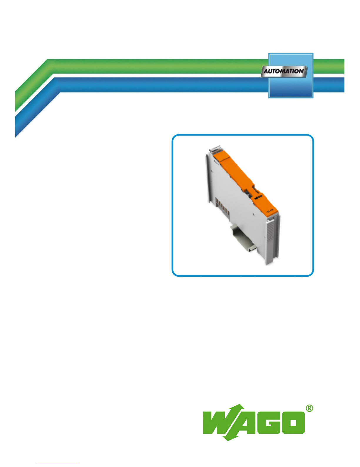
Manual
WAGO-I/O-SYSTEM 750
Separation module
750-616
Separation module without power jumper contacts
Version 1.0.4
Pos: 3 /Alle Serien (Allg emeine Mod ule)/Hinweis e zur Doku mentation/Im pressum für Standardhan dbücher - all g . A ngaben, Ansc hr i ft e n, Tel efonnummer n und E-Mail-Adr es sen @ 3\mod_1219151118203_21.docx @ 21060 @ @ 1
Page 2

2 WAGO-I/O-SYSTEM 750
750-616 Separation module
Manual
Version 1.1.0
© 2014 by WAGO Kontakttechnik GmbH & Co. KG
All rights reserved.
WAGO Kontakttechnik GmbH & Co. KG
Hansastraße 27
D-32423 Minden
Phone: +49 (0) 571/8 87 – 0
Fax: +49 (0) 571/8 87 – 1 69
E-Mail: info@wago.com
Web: http://www.wago.com
Technical Support
Phone: +49 (0) 571/8 87 – 5 55
Fax: +49 (0) 571/8 87 – 85 55
E-Mail: support@wago.com
Every conceivable measure has been taken to ensure the accuracy and
completeness of this documentation. However, as errors can never be fully
excluded, we always appreciate any information or suggestions for improving the
documentation.
E-Mail: documentation@wago.com
We wish to point out that the software and hardware terms as well as the
trademarks of companies used and/or mentioned in the present manual are
generally protected by trademark or patent.
=== Ende der Liste für T extmarke Ei nband_vorn e ===
Page 3

WAGO-I/O-SYSTEM 750 Table of Contents 3
750-616 Separation module
Manual
Version 1.1.0
Pos: 5 /Dok umentation al lgemein/V erzeichnisse /Inhaltsverz eichnis - Üb er s chr i f t oG und Verzeic h ni s @ 3\ mod_1219151230875_21.docx @ 21063 @ @ 1
Table of Contents
1 Notes about this Documentation ................................................................. 5
1.1 Validity of this Documentation ................................................................. 5
1.2 Copyright ................................................................................................... 5
1.3 Symbols ..................................................................................................... 6
1.4 Number Notation ....................................................................................... 8
1.5 Font Conventions ...................................................................................... 8
2 Important Notes ........................................................................................... 9
2.1 Legal Bases ............................................................................................... 9
2.1.1 Subject to Changes ............................................................................... 9
2.1.2 Personnel Qualifications ....................................................................... 9
2.1.3 Use of the WAGO-I/O-SYSTEM 750 in Compliance with Underlying
Provisions ............................................................................................. 9
2.1.4 Technical Condition of Specified Devices ......................................... 10
2.2 Safety Advice (Precautions) .................................................................... 11
3 Device Description ..................................................................................... 13
3.1 View ........................................................................................................ 13
3.2 Connectors ............................................................................................... 14
3.2.1 Data Contacts/Internal Bus ................................................................. 14
3.2.2 Power Jumper Contacts/Field Supply ................................................ 14
3.2.3 CAGE CLAMP® Connectors ............................................................. 15
3.3 Display Elements .................................................................................... 15
3.4 Operating Elements ................................................................................. 15
3.5 Technical Data ........................................................................................ 16
3.5.1 Device data ......................................................................................... 16
3.5.2 Connection Type ................................................................................ 16
3.5.3 Climatic Environmental Conditions ................................................... 16
3.6 Approvals ................................................................................................ 17
3.7 Standards and Guidelines ........................................................................ 18
4 Mounting ..................................................................................................... 19
4.1 Mounting Sequence ................................................................................. 19
4.2 Inserting and Removing Devices ............................................................ 20
4.2.1 Inserting the I/O Module .................................................................... 20
4.2.2 Removing the I/O Module .................................................................. 21
5 Connect Devices ......................................................................................... 22
5.1 Data Contacts/Internal Bus ..................................................................... 22
6 Use in Hazardous Environments .............................................................. 23
6.1 Marking Configuration Examples ........................................................... 24
6.1.1 Marking for Europe according to ATEX and IEC-Ex ........................ 24
6.1.2 Marking for America according to NEC 500 ..................................... 29
6.2 Installation Regulations ........................................................................... 30
6.2.1 Special Conditions for Safe Use (ATEX Certificate TÜV 07 ATEX
554086 X) ........................................................................................... 31
6.2.2 Special Conditions for Safe Use (ATEX Certificate TÜV 12 ATEX
106032 X) ........................................................................................... 32
Page 4

4 Table of Contents WAGO-I/O-SYSTEM 750
750-616 Separation module
Manual
Version 1.1.0
6.2.3 Special Conditions for Safe Use (IEC-Ex Certificate TUN 09.0001 X)33
6.2.4 Special Conditions for Safe Use (IEC-Ex Certificate IECEx TUN
12.0039 X) .......................................................................................... 34
6.2.5 Special Conditions for Safe Use according to ANSI/ISA 12.12.01 ... 35
List of Figures ...................................................................................................... 36
List of Tables ........................................................................................................ 37
=== Ende der Liste für T extmarke Ver zeichnis_v orne ===
Page 5
WAGO-I/O-SYSTEM 750 Notes about this Documentation 5
750-616 Separation module
Manual
Version 1.1.0
Pos: 7 /Alle Serien (Allg emeine Mod ule)/Übersc hriften für alle Serien/H inweis zur Dokumentat ion/Hinweis e zu dieser D okumentati on - Überschr i ft 1 @ 4\ mod_1237987661750_21.docx @ 29029 @ 1 @ 1
1 Notes about this Documentation
Pos: 8 /Alle Serien (Allg emeine Mod ule)/Hinwei se zur Doku mentation/Hi nweise/Hin weis: Dokum entation auf bewahren @ 4\mod_1237987339812 _21.docx @ 29026 @ @ 1
Keep this documentation!
The operating instructions are part of the product and shall be kept for the entire
lifetime of the product. They shall be transferred to each subsequent user of the
product. Care must also be taken to ensure that any supplement to these
instructions are included, if applicable.
Pos: 9 /Alle Serien (Allg emeine Mod ule)/Übersc hriften für alle Serien/H inweis zur Dokumentat ion/Gültig keitsbereich - Überschrift 2 @ 12 \mod_1338912448776_21.docx @ 96469 @ 2 @ 1
1.1 Validity of this Documentation
Pos: 10 /Seri e 750 (WAG O-I/O-SYSTEM)/ Hinweise z ur Dokument ation/Gültig keitsbereic h/Gültigkei tsbereich Do kumentatio n Busklemme 750-xxxx, Sta ndardversi on und aufg elistete Vari anten @ 14\mod_1358944038682_21.docx @ 109354 @ @ 1
This documentation is only applicable to the I/O module 750-616 (Separation
module ) and the variants listed in the table below.
Pos: 11 /Seri e 750 (WAG O-I/O-SYSTEM)/ Hinweise z ur Dokument ation/Gültig keitsbereic h/Variante nlisten/Vari antenliste - 750-616 - Sta ndardversion und Variant e /030-000 @ 20 \mod_1408365572094_21.docx @ 161932 @ @ 1
Table 1: Versions
Item No./Version
Designation
750-616
Separation module without marking
750-616/030-000
Separation module with “24 V DC/230 V AC”
marking
Pos: 12 /Serie 750 (WAGO-I/O-SYSTEM)/Hi nweise zur D okumentati on/Hinweise /Achtung: Hi nweis zur D okumentati on Busklemme n 750-xxxx und Varianten @ 20\mod_1407501360890_21.docx @ 161455 @ @ 1
The I/O module 750-616 and its variant/s shall only be installed and operated
according to the instructions in this manual and in the manual for the used
fieldbus coupler/controller.
Consider power layout of the WAGO-I/O-SYSTEM 750!
In addition to these operating instructions, you will also need the manual for the
used fieldbus coupler/controller, which can be downloaded at www.wago.com.
There, you can obtain important information including information on electrical
isolation, system power and supply specifications.
Pos: 13.1 /Al le Serien ( Allgemeine M odule)/Hi nweise zur D okumentation /Urhebersc hutz ausführ lich @ 4\mod_1235565145234_21.docx @ 27691 @ 2 @ 1
1.2 Copyright
This Manual, including all figures and illustrations, is copyright-protected. Any
further use of this Manual by third parties that violate pertinent copyright
provisions is prohibited. Reproduction, translation, electronic and phototechnical
filing/archiving (e.g., photocopying) as well as any amendments require the
written consent of WAGO Kontakttechnik GmbH & Co. KG, Minden, Germany.
Non-observance will involve the right to assert damage claims.
Pos: 13.2 /Doku m e nt a ti o n al l g e mein/Glieder ungselemente/---Seitenwechsel--- @ 3\mod_1221108045078_0.docx @ 21810 @ @ 1
Page 6
6 Notes about this Documentation WAGO-I/O-SYSTEM 750
750-616 Separation module
Manual
Version 1.1.0
Pos: 13.3 /Al le Serien ( Allgemeine M odule)/Über schriften f ür alle Seri en/Hinweis z ur Dokument ation/Symb ole - Überschr ift 2 @ 13\mod_1351068042408_21.docx @ 105270 @ 2 @ 1
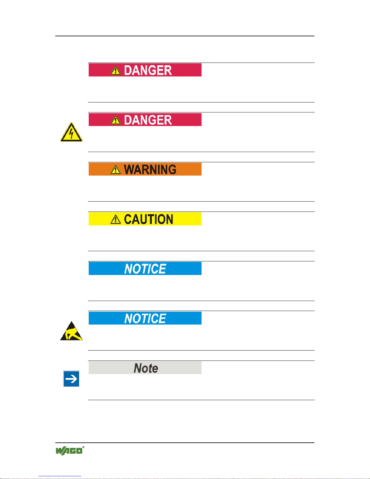
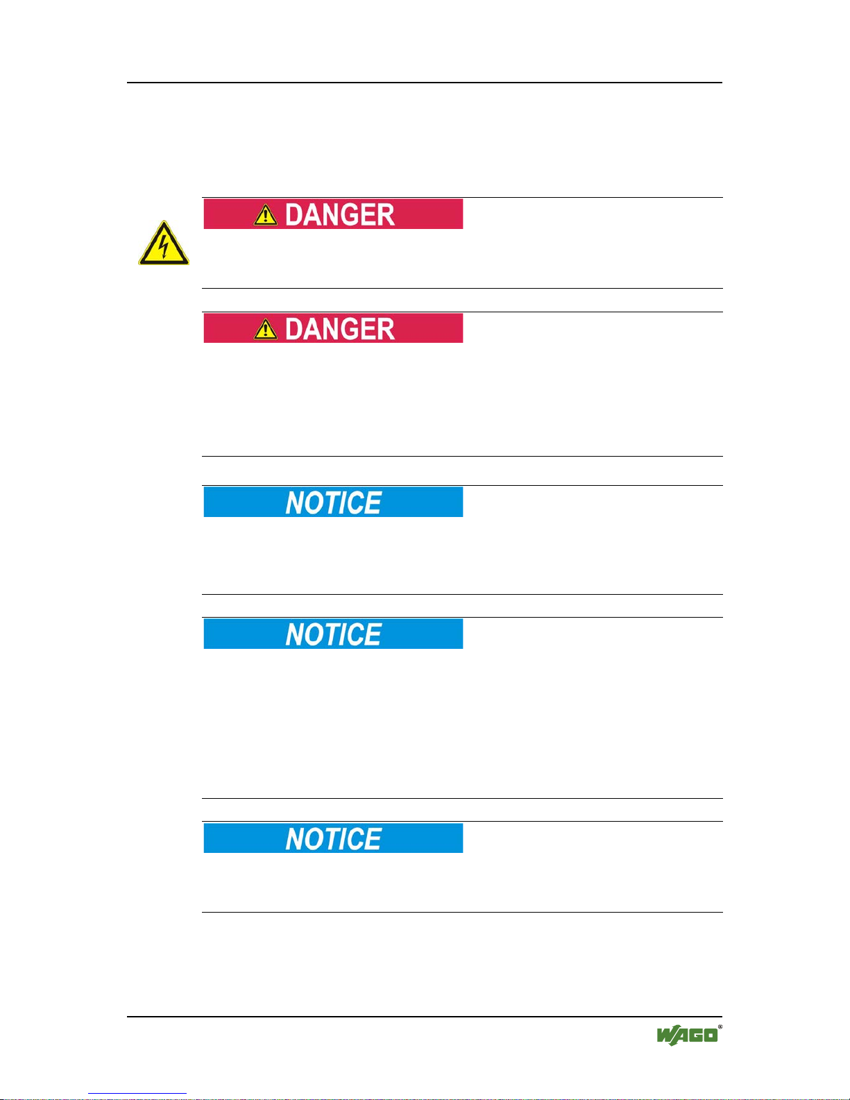
1.3 Symbols
Pos: 13.4.1 /All e Serien (Allg e mei ne Module)/Wi c htige Erläut er u ng e n/Sicherhei ts - und sonstige Hinweise/Gefahr/Gefahr: _Warnung vor Personenschäden allgemein_ - Erläuterung @ 13\mod_1343309450020_21.docx @ 101029 @ @ 1
Personal Injury!
Indicates a high-risk, imminently hazardous situation which, if not avoided, will
result in death or serious injury.
Pos: 13.4.2 /All e Serien (Allg e mei ne Module)/Wi c htige Erläut er u ng e n/Sicherhei ts - und sonstige Hin weise/Gefa hr/Gefahr: _ War nung vor Perso n en schäden durc h el e k tr i s c he n Strom_ - Erläuterung @ 13\mod_1343309694914_21.docx @ 101030 @ @ 1
Personal Injury Caused by Electric Current!
Indicates a high-risk, imminently hazardous situation which, if not avoided, will
result in death or serious injury.
Pos: 13.4.3 /All e Serien (Allg e mei ne Module)/Wi c htige Erläut er u ng e n/Sicherhei ts - und sonstig e Hinweise/ Warnung/War nung: _Warn ung vor Per sonenschäde n allgemei n_ - Erläuterung @ 13\mod_1343309877041_21.docx @ 101035 @ @ 1
Personal Injury!
Indicates a moderate-risk, potentially hazardous situation which, if not avoided,
could result in death or serious injury.
Pos: 13.4.4 /All e Serien (Allg e mei ne Module)/Wi c htige Erläut er u ng e n/Sicherhei ts - und sonstig e Hinweise/ Vorsicht/Vor sicht: _Warnu ng vor Personens c häden allgem ei n _ - Erläuterung @ 13\mod_1343310028762_21.docx @ 101038 @ @ 1
Personal Injury!
Indicates a low-risk, potentially hazardous situation which, if not avoided, may
result in minor or moderate injury.
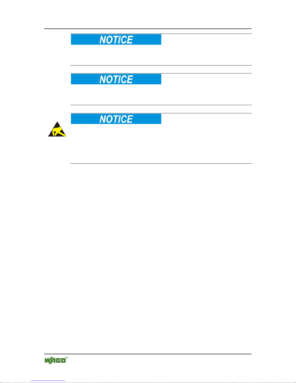
Pos: 13.4.5 /All e Serien (Allg e mei ne Module)/Wi c htige Erläut er u ng e n/Sicherhei ts - und sonstige Hinweise/Achtung/Achtung: _Warnung vor Sachschäden allgemein_ - Erläuterung @ 13\mod_1343310134623_21.docx @ 101041 @ @ 1
Damage to Property!
Indicates a potentially hazardous situation which, if not avoided, may result in
damage to property.
Pos: 13.4.6 /All e Serien (Allg e mei ne Module)/Wi c htige Erläut er u ng e n/Sicherhei ts - und sonstige Hinweise/Achtung/Achtung: _Warnung vor Sachschäden durch elektr ost atische Aufl a du ng _ - Erläuterung @ 13\mod_1343310227702_21.docx @ 101044 @ @ 1
Damage to Property Caused by Electrostatic Discharge (ESD)!
Indicates a potentially hazardous situation which, if not avoided, may result in
damage to property.
Pos: 13.4.7 /All e Serien (Allg e mei ne Module)/Wi c htige Erläut er u ng e n/Sicherhei ts - und sonstige Hinweise/Hinweis/Hinweis: _Wichtiger Hinweis allgemein_ - Erläuterung @ 13\mod_1343310326906_21.docx @ 101047 @ @ 1
Important Note!
Indicates a potential malfunction which, if not avoided, however, will not result in
damage to property.
Pos: 13.4.8 /All e Serien (Allg e mei ne Module)/Wi c htige Erläut er u ng e n/Sicherhei ts - und sonstig e Hinweise/I nformation/I nformatio n: _Weitere I nformation al l g e mei n_ - Erläuter ung @ 13 \ mod_1343310439814_21.docx @ 101051 @ @ 1
Page 7
WAGO-I/O-SYSTEM 750 Notes about this Documentation 7
750-616 Separation module
Manual
Version 1.1.0
Additional Information:
Refers to additional information which is not an integral part of this
documentation (e.g., the Internet).
Pos: 13.5 /Dokumentation allgemein/Gli ederungsele mente/---Seite nwechsel--- @ 3\mod_1221108045078_0.docx @ 21810 @ @ 1
Page 8
8 Notes about this Documentation WAGO-I/O-SYSTEM 750
750-616 Separation module
Manual
Version 1.1.0
Pos: 13.6 /Alle Ser i en (Allgemei ne Module)/Hi n weis e zur Dokument ation/Zahle nsysteme @ 3\mod_1221059454015_21.docx @ 21711 @ 2 @ 1
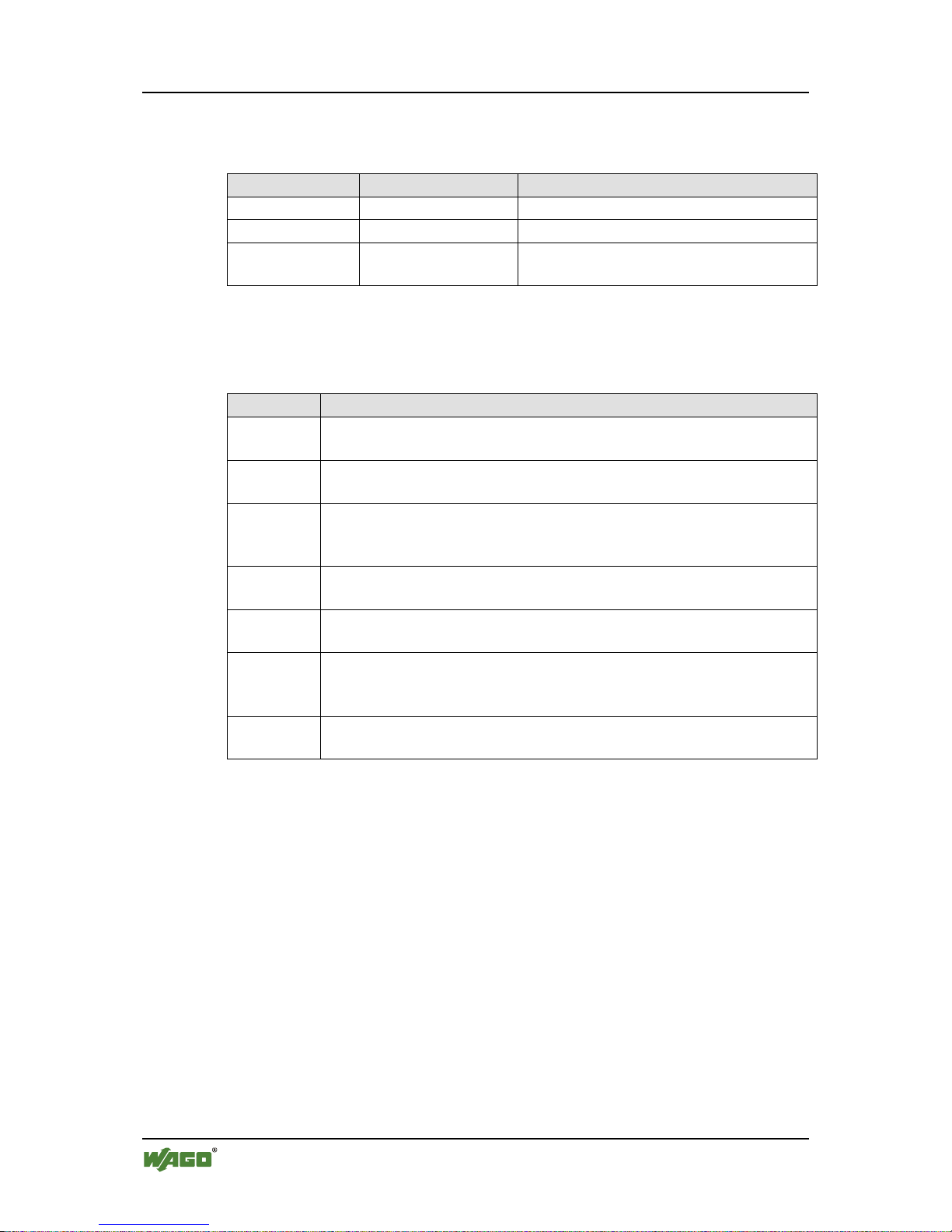
1.4 Number Notation
Table 2: Number notation
Number code
Example
Note
Decimal
100
Normal notation
Hexadecimal
0x64
C notation
Binary
'100'
'0110.0100'
In quotation marks, nibble separated with
dots (.)
Pos: 13.7 /Al le Serien ( Allgemeine M odule)/Hi nweise zur Dokumentation/Schriftkonventionen @ 3\mod_1221059521437_21.docx @ 21714 @ 2 @ 1
1.5 Font Conventions
Table 3: Font conventions
Font type
Indicates
italic
Names of paths and data files are marked in italic-type.
e.g.: C:\Programme\WAGO-I/O-CHECK
Menu
Menu items are marked in bold letters.
e.g.: Save
>
A greater-than sign between two names means the selection of a
menu item from a menu.
e.g.: File > New
Input
Designation of input or optional fields are marked in bold letters,
e.g.: Start of measurement range
“Value”
Input or selective values are marked in inverted commas.
e.g.: Enter the value “4 mA” under Start of measurement range.
[Button]
Pushbuttons in dialog boxes are marked with bold letters in square
brackets.
e.g.: [Input]
[Key]
Keys are marked with bold letters in square brackets.
e.g.: [F5]
Pos: 14 /Dokum e nt at i o n al l g e mei n/Glieder ung s elemente/---Sei tenwechsel--- @ 3\ mod_1221108045078_0.docx @ 2181 0 @ @ 1
Page 9

WAGO-I/O-SYSTEM 750 Important Notes 9
750-616 Separation module
Manual
Version 1.1.0
Pos: 15 /Alle Seri en (Allgemei n e Mo d ul e) / Ü berschrifte n für alle Serie n/ Wi c h ti g e Er läuterungen /Wichtige Er l ä uter ungen - Übers c hr i f t 1 @ 4\ mod_1241428899156_21.docx @ 32170 @ 1 @ 1
2 Important Notes
Pos: 16.1 /Alle Ser i en (Allgemei ne Module)/ Wichtige Erl äuterungen/ Einleitung Wichtige Erl äuterungen @ 3\mod_1221059818031_21.docx @ 21717 @ @ 1
This section includes an overall summary of the most important safety
requirements and notes that are mentioned in each individual section. To protect
your health and prevent damage to devices as well, it is imperative to read and
carefully follow the safety guidelines.
Pos: 16.2 /Al le Serien ( Allgemeine M odule)/Über schriften f ür alle Seri en/Wichtig e Erläuteru ngen/Rechtli che Grundlag en - Überschr ift 2 @ 3\mod_1221060626343_21.docx @ 21726 @ 2 @ 1
2.1 Legal Bases
Pos: 16.3 /Al le Serien ( Allgemeine M odule)/Wic htige Erläut erungen/Än derungsvor behalt - Übers chrift 3 un d Inhalt @ 3\mod_1221060036484_21.docx @ 21720 @ 3 @ 1
2.1.1 Subject to Changes
WAGO Kontakttechnik GmbH & Co. KG reserves the right to provide for any
alterations or modifications that serve to increase the efficiency of technical
progress. WAGO Kontakttechnik GmbH & Co. KG owns all rights arising from
the granting of patents or from the legal protection of utility patents. Third-party
products are always mentioned without any reference to patent rights. Thus, the
existence of such rights cannot be excluded.
Pos: 16.4 /Serie 750 (WAGO-I/O-SYSTEM)/ Wi c ht i g e Er l ä ut erungen/Per s onalqualifi kationPersonalqualifikation 750-xxxx - Überschrift 3 und Inhalt @ 3\ mod_1224061208046_21.docx @ 24063 @ 3 @ 1
2.1.2 Personnel Qualifications
All sequences implemented on WAGO-I/O-SYSTEM 750 devices may only be
carried out by electrical specialists with sufficient knowledge in automation. The
specialists must be familiar with the current norms and guidelines for the devices
and automated environments.
All changes to the coupler or controller should always be carried out by qualified
personnel with sufficient skills in PLC programming.
Pos: 16.5 /Serie 750 (WAGO-I/O-SYSTEM)/Wichtige Erläuterungen/Bestim m ungsgemäße VerwendungBestimmungsgemäße Verwendung 750-xxxx - Überschrift 3 und Inhalt @ 3\mod_1224064151234_21.docx @ 24070 @ 3 @ 1
2.1.3 Use of the WAGO-I/O-SYSTEM 750 in Compliance with
Underlying Provisions
Fieldbus couplers, fieldbus controllers and I/O modules found in the modular
WAGO-I/O-SYSTEM 750 receive digital and analog signals from sensors and
transmit them to actuators or higher-level control systems. Using programmable
controllers, the signals can also be (pre-) processed.
The devices have been developed for use in an environment that meets the IP20
protection class criteria. Protection against finger injury and solid impurities up to
12.5 mm diameter is assured; protection against water damage is not ensured.
Unless otherwise specified, operation of the devices in wet and dusty
environments is prohibited.
Operating the WAGO-I/O-SYSTEM 750 devices in home applications without
further measures is only permitted if they meet the emission limits (emissions of
interference) according to EN 61000-6-3. You will find the relevant information
in the section “Device Description” > “Standards and Guidelines” in the manual
for the used fieldbus coupler/controller.
Page 10

10 Important Notes WAGO-I/O-SYSTEM 750
750-616 Separation module
Manual
Version 1.1.0
Appropriate housing (per 94/9/EG) is required when operating the WAGO-I/OSYSTEM 750 in hazardous environments. Please note that a prototype test
certificate must be obtained that confirms the correct installation of the system in
a housing or switch cabinet.
Pos: 16.6 /Al le Serien ( Allgemeine M odule)/Wic htige Erläut erungen/Tec hnischer Z ustand der G eräte - Übersc hrift 3 und Inhal t @ 3\ mod_1221060446109_21.docx @ 21723 @ 3 @ 1
2.1.4 Technical Condition of Specified Devices
The devices to be supplied ex works are equipped with hardware and software
configurations, which meet the individual application requirements. WAGO
Kontakttechnik GmbH & Co. KG will be exempted from any liability in case of
changes in hardware or software as well as to non-compliant usage of devices.
Please send your request for modified and new hardware or software
configurations directly to WAGO Kontakttechnik GmbH & Co. KG.
Pos: 16.7 /Dokumentation allgemein/Gliederungselemente/---Seitenwechsel--- @ 3\mod_1221108045078_0.docx @ 21810 @ @ 1
Page 11
WAGO-I/O-SYSTEM 750 Important Notes 11
750-616 Separation module
Manual
Version 1.1.0
Pos: 16.8 /Alle Ser i en (Allgemei ne Module)/Über s chriften für al l e S er i e n/ Wichtige Erlä uterungen/Si c herheitshi n w ei se - Überschrift 2 @ 6\ mod_1260180299987_21.docx @ 46724 @ 2 @ 1
2.2 Safety Advice (Precautions)
Pos: 16.9 /Al le Serien ( Allgemeine M odule)/Wic ht i g e Er l ä ut erungen/Si ch erheits- und sonstige Hi nweise/Einl eitung Sich erheitshinw eise Hardwar e @ 6\mod_1260180170493_21.do cx @ 46720 @ @ 1
For installing and operating purposes of the relevant device to your system the
following safety precautions shall be observed:
Pos: 16.10. 1 /Alle Serie n (Allgemei ne Module)/ Wichtige Er läuterungen /Sicherheits - und sonstig e Hinweise/ Gefahr/Gef ahr: Nicht an Geräten un ter Spannung arbeiten! @ 6\mod_1260180365327_21.docx @ 46727 @ @ 1
Do not work on devices while energized!
All power sources to the device shall be switched off prior to performing any
installation, repair or maintenance work.
Pos: 16.10. 2 /Serie 750 ( WAGO-I/O-SY STEM)/Wichtig e Erläuter ungen/Sicher heits- und s onstige Hin weise/Gefahr /Gefahr: Ei nbau 0750- xxxx nur in Gehäusen, Schränken oder elektrischen Betriebsräumen! @ 6\mod_1260180556692_21.docx @ 46731 @ @ 1
Installation only in appropriate housings, cabinets or in electrical operation
rooms!
The WAGO-I/O-SYSTEM 750 and its components are an open system. As such,
install the system and its components exclusively in appropriate housings,
cabinets or in electrical operation rooms. Allow access to such equipment and
fixtures to authorized, qualified staff only by means of specific keys or tools.
Pos: 16.10. 3 /Alle Serie n (Allgemei ne Module)/ Wichtige Er läuterungen /Sicherheits - und sonstig e Hinweise/ Gefahr/Gef ahr: Unfall verhütungsvor schriften b eachten! @ 6\mod_1260180657000_21.docx @ 46735 @ @ 1
Pos: 16.10. 4 /Alle Serie n (Allgemei ne Module)/ Wichtige Er läuterungen /Sicherheits - und sonstig e Hinweise/ Gefahr/Gef ahr: Auf normg erechten A nschluss ac hten! @ 6\mod_1260180753479_21.docx @ 46739 @ @ 1
Pos: 16.11. 1 /Alle Serie n (Allgemei ne Module)/ Wichtige Er läuterungen /Sicherheits - und sonstig e Hinweise/ Achtung/Ac htung: Defek te oder bes chädigte Ger äte austausc hen! @ 6\mod_1260180857358_21.docx @ 46743 @ @ 1
Replace defective or damaged devices!
Replace defective or damaged device/module (e.g., in the event of deformed
contacts), since the long-term functionality of device/module involved can no
longer be ensured.
Pos: 16.11. 2 /Alle Serie n (Allgemei ne Module)/ Wichtige Er läuterungen /Sicherheits - und sonstig e Hinweise/ Achtung/Ac htung: Gerät e vor kriec henden und i solierenden Stoffen sch ützen! @ 6\mod_1260181036216_21.docx @ 46747 @ @ 1
Protect the components against materials having seeping and insulating
properties!
The components are not resistant to materials having seeping and insulating
properties such as: aerosols, silicones and triglycerides (found in some hand
creams). If you cannot exclude that such materials will appear in the component
environment, then install the components in an enclosure being resistant to the
above-mentioned materials. Clean tools and materials are imperative for handling
devices/modules.
Pos: 16.11. 3 /Alle Serie n (Allgemei ne Module)/ Wichtige Er läuterungen /Sicherheits - und sonstige Hinweise/Achtung /Achtung: R einigung nur mit zulässi gen Material ien! @ 6\mod_1260181203293_21.docx @ 46751 @ @ 1
Clean only with permitted materials!
Clean soiled contacts using oil-free compressed air or with ethyl alcohol and
leather cloths.
Pos: 16.11. 4 /Alle Serie n (Allgemei ne Module)/ Wichtige Er läuterungen /Sicherheits - und sonstig e Hinweise/ Achtung/Ac htung: Kein Kontaktspray verwenden! @ 6\mod_1260181290808_21.docx @ 46755 @ @ 1
Page 12
12 Important Notes WAGO-I/O-SYSTEM 750
750-616 Separation module
Manual
Version 1.1.0
Do not use any contact spray!
Do not use any contact spray. The spray may impair contact area functionality in
connection with contamination.
Pos: 16.11. 5 /Alle Serie n (Allgemei ne Module)/ Wichtige Er läuterungen /Sicherheits - und sonstig e Hinweise/ Achtung/Ac htung: Verpol ung vermei den! @ 6\mod_1260184045744_21.docx @ 46767 @ @ 1
Do not reverse the polarity of connection lines!
Avoid reverse polarity of data and power supply lines, as this may damage the
devices involved.
Pos: 16.11. 6 /Alle Serie n (Allgemei ne Module)/ Wichtige Er läuterungen /Sicherheits - und sonstige Hinwei se/Achtung/Achtung: Elektrostatische Entladung vermeiden! @ 6\mod_1260181364729_21.docx @ 46759 @ @ 1
Avoid electrostatic discharge!
The devices are equipped with electronic components that may be destroyed by
electrostatic discharge when touched. Please observe the safety precautions
against electrostatic discharge per DIN EN 61340-5-1/-3. When handling the
devices, please ensure that environmental factors (personnel, work space and
packaging) are properly grounded.
Pos: 17 /Dokum e nt at i o n al l g e mei n/Glieder ung s elemente/---Sei tenwechsel--- @ 3\ mod_1221108045078_0.docx @ 21810 @ @ 1
Page 13

WAGO-I/O-SYSTEM 750 Device Descripti on 13
750-616 Separation module
Manual
Version 1.1.0
Pos: 18 /All e Serien (Al lgemeine Mo d ul e) /Ü berschrif te n für alle Serie n/G erätebesc hr eib ung/Geräte beschreibu ng - Überschrift 1 @ 3\ mod_1233756084656_21.docx @ 27096 @ 1 @ 1
3 Device Descrip t ion
Pos: 19.1.1 /Serie 750 ( WAGO-I/O-SYSTEM)/Gerätebeschreibun g/Einleitung/Anwendung/SY/Anwendung 750-0616 @ 20\mod_1408372024099_21.docx @ 161 962 @ @ 1
Dabei
The 750-616 I/O Module (Separation module ) and its versions visually and
electrically divide a fieldbus node into sections (e.g., different functional units).
Pos: 19.1.2 /Serie 750 ( WAGO-I/O-SYSTEM)/Wichtige Erläuterungen/Sicherheits- und sonstig e Hinweis e/Hinweis/Hi nweis: Pote ntialeinspei seklemme ei nsetzen! ( keine LK) @ 3 \mod_1226499089640_21.docx @ 25026 @ @ 1
Use a supply module!
Use a supply module for field-side power supply of downstream I/O modules.
Pos: 19.1.3 /Serie 750 ( WAGO-I/O-SYST EM)/Geräte beschreibung /Einleitung /Einsatzber eich/Eins atzbereich 7 50-xxxx alle Kop pl er/Controll er oh n e Einschränk ung @ 3\ mod_1232541691906_21.docx @ 26522 @ @ 1
The I/O module 750-616 can be used with all fieldbus couplers/controllers of the
WAGO-I/O-SYSTEM 750.
Pos: 19.2 /Dokumentation allgemein/Gliederungselemente/---Seitenwechsel--- @ 3\mod_1221108045078_0.docx @ 21810 @ @ 1
Pos: 19.3 /Alle Serien (Allgemeine Module)/Überschriften für alle Serien/Gerätebeschreibung/Ansicht - Überschrift 2 @ 4\mod_1240984217343_21.docx @ 31958 @ 2 @ 1
3.1 View
Pos: 19.4 /Serie 750 (WAGO-I/O-SYST EM)/Geräte b eschreibung / A ns i c ht /Systemkle mmen/Ansich t 75 0- 0616 @ 20\mod_1408354479608_21.docx @ 161888 @ @ 1
Figure 1: View
Pos: 19.5 /Serie 750 (WAGO-I/O-SYSTEM)/ Gerätebeschr eibung/Ansi cht/Ansic ht Distanzkl emme_ohne L eistungskont akte @ 20\mod_1408363641460_21.do cx @ 161917 @ @ 1
Table 4: Legend for the “View” Figure
Pos.
Description
Details See Section
1
Data contacts
“Device Description” > “Connectors”
2
Release tab
“Mounting” > ”Inserting and Removing
Devices”
Pos: 19.6 /Dokumentation allgemein/Gliederungselemente/---Seitenwechsel--- @ 3\mod_1221108045078_0.docx @ 21810 @ @ 1
Page 14

14 Device Descripti on WAGO-I/O-SYSTEM 750
750-616 Separation module
Manual
Version 1.1.0
Pos: 19.7 /Al le Serien ( Allgemeine M odule)/Über schriften f ür alle Seri en/Geräteb eschreibung /Anschlüsse - Überschrift 2 @ 4\ mod_1240984262656_21.docx @ 31961 @ 2 @ 1
3.2 Connectors
Pos: 19.8 /Serie 750 (WAGO-I/O-SYSTEM)/ Gerätebeschr eibung/Ansc hlüsse/Date nkontakte/Kl emmenbus - Überschrift 3 @ 6\ mod_1256294684083_21.docx @ 43660 @ 3 @ 1
3.2.1 Data Contacts/Internal Bus
Pos: 19.9.1 /Ser i e 750 (WAGO-I/O-SYSTEM)/Gerätebeschreibung/Anschlüsse/Datenkontakte - Feldbuskoppl er/-controller , Abbildung und Beschr eibung @ 3\mod_1231771259187_21.docx @ 26002 @ @ 1
Communication between the fieldbus coupler/controller and the I/O modules as
well as the system supply of the I/O modules is carried out via the internal bus. It
is comprised of 6 data contacts, which are available as self-cleaning gold spring
contacts.
Figure 2: Data contacts
Pos: 19.9.2 /Serie 750 ( WAGO-I/O-SYSTEM)/Wichtige Erläuterungen/Sicherheits- und sonstige Hinweise/A chtung/Ach tung: Buskl emmen nicht auf Goldfe derkontakte l egen! @ 7\mod_1266318463636_21.docx @ 50695 @ @ 1
Do not place the I/O modules on the gold spring contacts!
Do not place the I/O modules on the gold spring contacts in order to avoid soiling
or scratching!
Pos: 19.9.3 /Serie 750 ( WAGO-I/O-SYSTEM)/Wichtige Erläuterungen/Sicherheits- und sonstige Hinweise/Achtung/Achtung: ESD - Auf gute Erdung der Umg eb u ng achten! @ 7\mod_1266318538667_21.docx @ 50708 @ @ 1
Ensure that the environment is well grounded!
The devices are equipped with electronic components that may be destroyed by
electrostatic discharge. When handling the devices, ensure that the environment
(persons, workplace and packing) is well grounded. Avoid touching conductive
components, e.g. data contacts.
Pos: 19.10 / Serie 750 ( WAGO-I/O-SYST EM)/Gerätebe schreibung /Anschlüsse/ Leistungs kontakte/Fel dversorgung - Überschrif t 3 @ 6\mod_1256294692864_21.docx @ 43664 @ 3 @ 1
3.2.2 Power Jumper Contacts/Field Supply
Pos: 19.11 / Serie 750 ( WAGO-I/O-SYST EM)/Wichtig e Erläuterung en/Sicher heits- und so nstige Hinw eise/Hinweis /Hinweis: P otentialein speiseklemm e einsetzen! (keine LK) @ 3\mod_1226499089640_21.docx @ 25026 @ @ 1
Use a supply module!
Use a supply module for field-side power supply of downstream I/O modules.
Pos: 19.12 /Ser i e 7 50 ( WAGO-I/O-SYST EM ) /G erätebeschr eibung/Ansc hlüsse/Lei st ungskontak t e ni c h t v or h an d en (Standard+ Variante/n) @ 20\ mod_1410163910476_21.docx @ 162161 @ @ 1
The I/O module 750-616 and its variant have no power jumper contacts.
Pos: 19.13 / Serie 750 (W AGO-I/O-SYST EM)/Gerätebe schreibung /Anschlüsse/C AGE CLAMP -Anschlüsse - Übersc hr i ft 3 @ 6\ mod_1256296337770_21.docx @ 43674 @ 3 @ 1
Page 15

WAGO-I/O-SYSTEM 750 Device Descripti on 15
750-616 Separation module
Manual
Version 1.1.0
3.2.3 CAGE CLAMP® Connectors
Pos: 19.14 / Serie 750 ( WAGO-I/O-SYST EM)/Gerätebe schreibung /Anschlüsse/ CAGE CLAM P-Anschlüsse 750-xxxx nicht vorhanden - mi t Variante @ 20\mod_1410164232649_21.docx @ 162165 @ @ 1
The I/O module 750-616 and its variant have no CAGE CLAMP® connections.
Pos: 19.15 /D okumentati on allgemei n/Gliederung selemente/---S eitenwechs el--- @ 3\mod_1221108045078_0.docx @ 21810 @ @ 1
Pos: 19.16 / Alle Serien ( Allgemeine M odule)/Üb erschriften für alle Seri en/Geräte beschreibung /Anzeigeel emente - Übers chrift 2 @ 4\mod_124098439087 5_21.docx @ 31964 @ 2 @ 1
3.3 Display Elements
Pos: 19.17 / Serie 750 ( WAGO-I/O-SYST EM ) / G er ät ebeschreib u ng/Anzeigeel emente/An zei g e elemente 75 0- xxxx nicht vorhanden - mit Variante @ 2 0\mod_1410164633909_21.docx @ 162739 @ @ 1
The I/O module 750-616 and its variant have no display elements.
Pos: 19.18 / Alle Serien ( Allgemeine M odule)/Üb erschriften für alle Seri en/Geräte beschreibung /Bedienele mente - Übersc hrift 2 @ 4\mod_1239191655456_21.docx @ 30439 @ 2 @ 1
3.4 Operating Elements
Pos: 19.19 / Serie 750 ( WAGO-I/O-SYST EM)/Gerätebe schreibung /Bedienele mente/Bedie nelemente B usklemme 750- xxxx nicht vorh anden (Stand ar d+ Variante/n) @ 20 \ mod_1410164753164_21.docx @ 162743 @ @ 1
The I/O module 750-616 and its variant/s have no operating elements.
Pos: 19.20 /D okumentati on allgemei n/Gliederung selemente/---S eitenwechs el--- @ 3\mod_1221108045078_0.docx @ 21810 @ @ 1
Page 16

16 Device Descripti on WAGO-I/O-SYSTEM 750
750-616 Separation module
Manual
Version 1.1.0
Pos: 19.21 / Alle Serien ( Allgemeine M odule)/Üb erschriften für alle Seri en/Geräte beschreibung /Technisch e Daten - Übers c hrift 2 @ 3\mod_1232967587687_21.docx @ 26924 @ 2 @ 1
3.5 Technical Data
Pos: 19.22 / Serie 750 ( WAGO-I/O-SYST EM)/Gerätebe schreibung /Technische D aten/Syst emklemmen/T echnische D aten 750-0616 @ 20\mod_1408368833060_21.docx @ 161958 @ 3 @ 1
3.5.1 Device data
Table 5: Technical data – device
Width
12 mm
Height (from upper edge of 35 DIN rail)
64 mm
Depth
100 mm
Weight
38.9 g
Pos: 19.23 / Alle Serien ( Allgemeine M odule)/Üb erschriften für alle Seri en/Geräte beschreibung /Anschluss technik - Über schrift 3 @ 17\mod_1380123271324_21.docx @ 132788 @ 3 @ 1
3.5.2 Connection Type
Pos: 19.24 / Serie 750 ( WAGO-I/O-SYST EM ) / G er ät ebeschreib u ng/Technisc h e D at e n/Anschluss t ec hnik/Techni s c he Daten Klemm en bus @ 17\mod_1380123495844_21.docx @ 132794 @ @ 1
Table 6: Technical Data – Interna l Bus
Data contacts
slide contact, hard gold plated, selfcleaning
Pos: 19.25 / Serie 750 ( WAGO-I/O-SYST EM)/Gerätebe schreibung /Technische D aten/Klim atische Um weltbedingung en/Technis che Daten Kl imatische U mweltbeding ungen o. er w. Tempberei ch; 0...55 °C/-25...+85° C @ 5\mod_1247657968368_21.docx @ 37603 @ 3 @ 1
3.5.3 Climatic Environmental Conditions
Table 7: Technical Data – Climatic Environmental Conditions
Operating temperature range
0 °C … 55 °C
Storage temperature range
-25 °C … +85 °C
Relative humidity without condensation
Max. 95 %
Resistance to harmful substances
Acc. to IEC 60068-2-42 and
IEC 60068-2-43
Maximum pollutant concentration at
relative humidity < 75 %
SO2 ≤ 25 ppm
H2S ≤ 10 ppm
Special conditions
Ensure that additional measures for
components are taken, which are used in
an environment involving:
– dust, caustic vapors or gases
– ionizing radiation
Pos: 19.26 /D okumentati on allgemei n/Gliederung selemente/---S eitenwechs el--- @ 3\mod_1221108045078_0.docx @ 21810 @ @ 1
Page 17

WAGO-I/O-SYSTEM 750 Device Descripti on 17
750-616 Separation module
Manual
Version 1.1.0
Pos: 19.27 / Alle Serien ( Allgemeine M odule)/Üb erschriften für alle Seri en/Geräte beschreibung /Zulassunge n - Überschri ft 2 @ 3\mod_1224055364109_21.docx @ 24030 @ 2 @ 1
3.6 Approvals
Pos: 19.28 / Serie 750 ( WAGO-I/O-SYST EM)/Gerätebe schreibung /Zulassung en/Informati on: Weiter e Informatio nen zu Zulassungen 750-xxxx @ 3\mod_1227190967156_21.docx @ 25221 @ @ 1
More information about approvals.
Detailed references to the approvals are listed in the document “Overview
Approvals WAGO-I/O-SYSTEM 750”, which you can find via the internet
under: www.wago.com > SERVICES > DOWNLOADS > Additional
documentation and information on automation products > WAGO-I/O-SYSTEM
750 > System Description.
Pos: 19.29 / Serie 750 ( WAGO-I/O-SYST EM)/Gerätebe schreibung /Zulassung en/Allgemein/ Zulassung en B usklemme 750- xxxx Allgemei n, ohne Variant e na ngabe - Einlei tung @ 4\mod_1237460656921_21.docx @ 28643 @ @ 1
The following approvals have been granted to 750-616 I/O modules:
Pos: 19.30. 1 /Alle Serie n (Allgemei ne Dokument e) (Allgemei ne Module) /Zulassunge n/Standardzul assungen/ CE (Konfor mitätskennzei chnung) @ 3\mod_1224494777421_21.docx @ 24276 @ @ 1
Conformity Marking
Pos: 19.30. 2 /Alle Serie n (Allgemei ne Dokument e) (Allgemei ne Module) /Zulassunge n/Standardzul assungen/ cULus (UL50 8) @ 3\ mod_1224055013140_0.docx @ 24020 @ @ 1
CULUS
UL508
Pos: 19.30. 3 /Dokument ation allgem ein/Glieder ungselement e/------Leerzeile------ @ 3\mod_1224662755687_0.docx @ 24460 @ @ 1
Pos: 19.31 / Serie 750 ( WAGO-I/O-SYST EM)/Gerätebe schreibung /Zulassung en/Ex/Zulass ungen Buskl emme 750-xx xx E x, o hn e Variantenang abe - Einleit ung @ 4\mod_1237191218000_21.doc x @ 28 42 3 @ @ 1
The following Ex approvals have been granted to 750-616 I/O modules:
Pos: 19.32. 1 /Alle Serie n (Allgemei ne Module)/Z ulassunge n/Ex-Zulass ung e n/T Ü V ATEX/TÜV 0 7 AT E X 55 4086 X: I M2 Ex d I Mb II 3 G E x nA IIC T4 Gc II 3 D Ex tc IIIC T135°C Dc @ 14\mod_1361949753233_0.docx @ 113015 @ @ 1
TÜV 07 ATEX 554086 X
I M2 Ex d I Mb
II 3 G Ex nA IIC T4 Gc
II 3 D Ex tc IIIC T135°C Dc
Pos: 19.32. 2 /Alle Serie n (Allgemei ne Module)/Z ulassunge n/Ex-Zulass ungen/Ergänzu ng Zulässi ger Umgebung stemperatur bereich 0 °C <= Ta <= + 60 °C @ 9\mod_1295605895541_21.docx @ 6861 0 @ @ 1
Ambient temperature range:
0 °C ≤ T
a
≤ +60 °C
Pos: 19.32. 3 /Alle Serie n (Allgemei ne Module)/Z ulassunge n/Ex-Zulass ungen/IECEx (T ÜV Nord)/ IECEx TUN 0 9.0001 X: E x d I Mb Ex nA IIC T4 Gc E x tc IIIC T135 °C @ 14\mod_1361950034299_0.docx @ 113019 @ @ 1
IECEx TUN 09.0001 X
Ex d I Mb
Ex nA IIC T4 Gc
Ex tc IIIC T135°C Dc
Pos: 19.32. 4 /Alle Serie n (Allgemei ne Module)/Z ulassunge n/Ex-Zulass ungen/Ergänzu ng Zulässi ger Umgebung stemperatur bereich 0 °C <= Ta <= + 60 °C @ 9\mod_1295605895541_21.docx @ 6861 0 @ @ 1
Ambient temperature range:
0 °C ≤ T
a
≤ +60 °C
Pos: 19.32. 5 /Alle Serie n (Allgemei ne Module)/Z ulassunge n/Ex-Zulass ungen/cULus/cU Lus (ANSI /ISA 12.12.0 1) Class I, D iv2 ABCD T4 @ 3\mod_1224054791812_0.docx @ 24014 @ @ 1
CULUS
ANSI/ISA 12.12.01
Class I, Div2 ABCD T4
Pos: 19.32. 6 /Dokument ation allgem ein/Glieder ungselement e/------Leerzeile------ @ 3\mod_1224662755687_0.docx @ 24460 @ @ 1
Pos: 19.33 / Serie 750 ( WAGO-I/O-SYST EM)/Gerätebe schreibung /Zulassung en/Schiff/Zul assungen B usklemme 7 50-xxxx Schif f, ohne Vari antenangab e - Einleitung @ 4\ mod_1237190918453_21.docx @ 28420 @ @ 1
The following ship approvals have been granted to 750-616 I/O modules:
Pos: 19.34. 1 /Alle Serie n (Allgemei ne Dokument e) (Allgemei ne Module) /Zulassunge n/Schiffszul assungen/ ABS (America n Bureau of S hipping) @ 3\mod_1224055151062_0.docx @ 24023 @ @ 1
ABS (American Bureau of Shipping)
Pos: 19.34. 2 /Alle Serie n (Allgemei ne Dokument e) (Allgemei ne Module) /Zulassunge n/ S c hi f f sz ulassunge n/ BV ( B ur eau Veritas) @ 3\ mod_1224492116171_0.docx @ 24220 @ @ 1
BV (Bureau Veritas)
Pos: 19.34. 3 /Alle Serie n (Allgemei ne Dokument e) (Allgemei ne Module) /Zulassunge n/Schiffszul assungen/DN V (Det Nor ske Veritas) Class B @ 3\ mod_1224492540562_0.docx @ 24224 @ @ 1
DNV (Det Norske Veritas) Class B
Pos: 19.34. 4 /Alle Serie n (Allgemei ne Dokument e) (Allgemei ne Module) /Zulassunge n/Schiffszul assungen/G L (Germanisc her Lloyd) C at. A, B, C, D (EMC 1) @ 3\mod_1224492724484_0.docx @ 24228 @ @ 1
GL (Germanischer Lloyd) Cat. A, B, C, D (EMC 1)
Pos: 19.34. 5 /Alle Serie n (Allgemei ne Dokument e) (Allgemei ne Module) /Zulassunge n/Schiffszul assungen/ KR (Korean Reg ister of S hipping) @ 3 \mod_1224492806109_0.docx @ 24232 @ @ 1
Page 18

18 Device Descripti on WAGO-I/O-SYSTEM 750
750-616 Separation module
Manual
Version 1.1.0
KR (Korean Register of Shipping)
Pos: 19.34. 6 /Alle Serie n (Allgemei ne Dokument e) (Allgemei ne Module) /Zulassunge n/Schiffszul assungen/ LR (Lloyd’s R egister) En v. 1, 2, 3, 4 @ 3\mod_1224492890453_0.docx @ 24236 @ @ 1
LR (Lloyd’s Register) Env. 1, 2, 3, 4
Pos: 19.34.7 /All e Serien (Allgemeine Dokumente) (Allgemeine Module)/Z ulassunge n/S chiffszulass ungen/PRS ( Pol s ki Rejestr Stat ków) @ 3\mod_1224497273250_0.docx @ 24295 @ @ 1
PRS (Polski Rejestr Statków)
Pos: 19.34. 8 /Alle Serie n (Allgemei ne Dokument e) (Allgemei ne Module) /Zulassunge n/Schiffszul assungen/RI NA (Registr o Italiano N avale) @ 3\ mod_1224493078359_0.docx @ 24244 @ @ 1
RINA (Registro Italiano Navale)
Pos: 19.34. 9 /Dokument ation allgem ein/Glieder ungselement e/------Leerzeile------ @ 3\mod_1224662755687_0.docx @ 24460 @ @ 1
Pos: 19.35 / Alle Serien ( Allgemeine M odule)/Üb erschriften für alle Seri en/Geräte beschreibung /Normen u nd Richtlinie n - Überschrif t 2 @ 4\mod_1242804031875_21.docx @ 33646 @ 2 @ 1
3.7 Standards and Guidelines
Pos: 19.36 / Serie 750 (W AGO-I/O-SYST EM)/Gerätebe schreibung /Normen und Richtlinien/ EMV-Normen B u s klemme 750-xxxx, ohne Variantenangabe - Einleitung @ 4\mod_1242803944015_21.docx @ 33642 @ @ 1
750-616 I/O modules meet the following requirements on emission and immunity
of interference:
Pos: 19.37 / Alle Serien ( Allgemeine M odule)/Nor men und Ric htlinien/EM V-Normen - Standard/EMV CE-Störaussendung EN 61000-6-4: 2007 @ 4\mod_1242798273984_21.docx @ 33602 @ @ 1
EMC CE-Emission of interference acc. to EN 61000-6-4: 2007
Pos: 19.38 / Alle Serien ( Allgemeine M odule)/Nor men und Ric htlinien/EM V-Normen - Standard/EMV CE-Störfestig keit EN 61000-6-2: 2005 @ 4\mod_1242797655625_21.docx @ 33591 @ @ 1
EMC CE-Immunity to interference acc. to EN 61000-6-2: 2005
Pos: 19.39 / Alle Serien ( Allgemeine M odule)/Nor men und Ric htlinien/EM V-Normen - Sc hi f f b au / EM V Schiffbau-St öraussend ung Germanis cher Lloyd (2003) @ 4\ mod_1242798400546_21.docx @ 33606 @ @ 1
EMC marine applications-Emission
of interference acc. to Germanischer Lloyd (2003)
Pos: 19.40 / Alle Serien ( Allgemeine M odule)/Nor men und Ric htlinien/EM V-Normen - Sc hi f f b au / EM V Schiffbau-St örfestigk ei t Ger manischer Llo yd (2003) @ 4\mod_1242798409640_21.docx @ 33610 @ @ 1
EMC marine applications-Immunity
to interference acc. to Germanischer Lloyd (2003)
Pos: 20 /Dokum e nt at i o n al l g e mei n/Glieder ung s elemente/---Sei tenwechsel--- @ 3\ mod_1221108045078_0.docx @ 21810 @ @ 1
Page 19

WAGO-I/O-SYSTEM 750 Mounting 19
750-616 Separation module
Manual
Version 1.1.0
Pos: 21 /All e Serien (Al lgemeine Mo dule)/Übers c hr if ten für alle Seri e n/Montieren - D emontieren/M ontieren - Ü b er s c hrift 1 @ 3\mod_1225446744750_21.docx @ 24900 @ 1 @ 1
4 Mounting
Pos: 22.1 /Serie 750 (WAGO-I/O-SYSTEM)/M ontieren/De montieren/M ontagereihe nfolge @ 3\mod_1231770210031_21.docx @ 25992 @ 2 @ 1
4.1 Mounting Sequence
Fieldbus couplers/controllers and I/O modules of the WAGO-I/O-SYSTEM 750
are snapped directly on a carrier rail in accordance with the European standard EN
50022 (DIN 35).
The reliable positioning and connection is made using a tongue and groove
system. Due to the automatic locking, the individual devices are securely seated
on the rail after installation.
Starting with the fieldbus coupler/controller, the I/O modules are mounted
adjacent to each other according to the project design. Errors in the design of the
node in terms of the potential groups (connection via the power contacts) are
recognized, as the I/O modules with power contacts (blade contacts) cannot be
linked to I/O modules with fewer power contacts.
Pos: 22.2 /S erie 750 (WAGO-I/O-SYSTEM)/Wi c htige Erläut er u ng e n/Sicherhei ts - und sonstige Hinweise/Achtung/Achtung: Busklemmen nur in vorgesehener Reihenfolge stecken! @ 6\mod_1256194177073_21.docx @ 43429 @ @ 1
Insert I/O modules only from the proper direction!
All I/O modules feature grooves for power jumper contacts on the right side. For
some I/O modules, the grooves are closed on the top. Therefore, I/O modules
featuring a power jumper contact on the left side cannot be snapped from the top.
This mechanical coding helps to avoid configuration errors, which may destroy
the I/O modules. Therefore, insert I/O modules only from the right and from the
top.
Pos: 22.3 /Serie 750 (WAGO-I/O-SYSTEM)/ Wi c ht i g e Er l ä ut erungen/Si ch erheits- und sonstige Hinweise/Hinweis/Hinweis: Bu s a bs c hluss nicht ver g es s en! @ 6\mod_1256194225557_21.docx @ 43432 @ @ 1
Don't forget the bus end module!
Always plug a bus end module 750-600 onto the end of the fieldbus node! You
must always use a bus end module at all fieldbus nodes with WAGO-I/OSYSTEM 750 fieldbus couplers/controllers to guarantee proper data transfer.
Pos: 22.4 /Dokumentation allgemein/Gliederungselemente/---Seitenwechsel--- @ 3\mod_1221108045078_0.docx @ 21810 @ @ 1
Page 20

20 Mounting WAGO-I/O-SYSTEM 750
750-616 Separation module
Manual
Version 1.1.0
Pos: 22.5 /Serie 750 (WAGO-I/O-SYSTEM)/M ontieren/De montieren/ Geräte einfüg en und entf ernen - Übers chrift 2 @ 3 \mod_1231768483250_21.docx @ 25950 @ 2 @ 1
4.2 Inserting and Removing De vices
Pos: 22.6 /Al le Serien ( Allgemeine M odule)/Wic htige Erläut erungen/Sic herheits- und sonstige Hi nweise/Ac htung/Achtu ng: Arbeiten an Geräten nur spannung sfrei durc hführen! @ 6 \mod_1256193963573_21.docx @ 43426 @ @ 1
Perform work on devices only if they are de-energized!
Working on energized devices can damage them. Therefore, turn off the power
supply before working on the devices.
Pos: 22.7 /Serie 750 (WAGO-I/O-SYSTEM)/M ontieren/De montieren/ B us klemme einfüg en @ 3\mod_1231769726703_21.docx @ 25989 @ 3 @ 1
4.2.1 Inserting the I/O Module
1. Position the I/O module so that the tongue and groove joints to the fieldbus
coupler/controller or to the previous or possibly subsequent I/O module are
engaged.
Figure 3: Insert I/O modu le (sample)
2. Press the I/O module into the assembly until the I/O module snaps into the
carrier rail.
Figure 4: Snap the I/O module into place (sample)
With the I/O module snapped in place, the electrical connections for the data
contacts and power jumper contacts (if any) to the fieldbus coupler/controller or to
the previous or possibly subsequent I/O module are established.
Pos: 22.8 /Dokumentation allgemein/Gliederungselemente/---Seitenwechsel--- @ 3\mod_1221108045078_0.docx @ 21810 @ @ 1
Page 21

WAGO-I/O-SYSTEM 750 Mounting 21
750-616 Separation module
Manual
Version 1.1.0
Pos: 22.9 /Serie 750 (WAGO-I/O-SYSTEM)/M ontieren/De montieren/ Busklemme e ntfernen @ 4 \mod_1239169375203_21.docx @ 30334 @ 3 @ 1
4.2.2 Removing the I/O Module
1. Remove the I/O module from the assembly by pulling the release tab.
Figure 5: Removing the I/O module (sample)
Electrical connections for data or power jumper contacts are disconnected when
removing the I/O module.
Pos: 23 /Dokum e nt at i o n al l g e mei n/Glieder ung s elemente/---Sei tenwechsel--- @ 3\ mod_1221108045078_0.docx @ 21810 @ @ 1
Page 22

22 Connect Devices WAGO-I/O-SYSTEM 750
750-616 Separation module
Manual
Version 1.1.0
Pos: 24 /All e Serien (Al lgemeine Mo dule)/Übers chriften für alle Serie n/Anschließe n/Geräte ans chließen - Ü berschrift 1 @ 3\mod_1234172889468_21. docx @ 27460 @ 1 @ 1
5 Connect Devices
Pos: 25 /Seri e 750 (WAG O-I/O-SYSTEM)/ Anschließe n/Datenkont akte/Klemm enbus - Übersc hrift 2 @ 7\ mod_1266320620183_21.docx @ 50718 @ 2 @ 1
5.1 Data Contacts/Internal Bus
Pos: 26 /Seri e 750 (WAG O-I/O-SYSTEM)/ Gerätebesc hreibung/Ans chlüsse/Da tenkontakt e - Feldbuskop pler/-control ler, Abbild ung und Besc hreibung @ 3\mod_1231771259187_21.docx @ 26002 @ @ 1
Communication between the fieldbus coupler/controller and the I/O modules as
well as the system supply of the I/O modules is carried out via the internal bus. It
is comprised of 6 data contacts, which are available as self-cleaning gold spring
contacts.
Figure 6: Data contacts
Pos: 27 /Seri e 750 (WAG O-I/O-SYSTEM)/ Wichtige Erl ä ut er u ngen/Sicher h ei t s- und sonstige Hinweise/Achtung/ Achtung: Bu sklemmen nic ht auf Gol dfederkonta kte legen! @ 7\mod_1266318463636_21.docx @ 50695 @ @ 1
Do not place the I/O modules on the gold spring contacts!
Do not place the I/O modules on the gold spring contacts in order to avoid soiling
or scratching!
Pos: 28 /Seri e 750 (WAG O-I/O-SYSTEM)/ Wichtige Erl ä ut er u ngen/Sicher h ei t s- und sonstige Hinwe i se/Achtung/Achtung: ESD - Auf gute Er dung der U mgebung acht en! @ 7\mod_1266318538667_21.docx @ 50708 @ @ 1
Ensure that the environment is well grounded!
The devices are equipped with electronic components that may be destroyed by
electrostatic discharge. When handling the devices, ensure that the environment
(persons, workplace and packing) is well grounded. Avoid touching conductive
components, e.g. data contacts.
Pos: 29 /Dokum e nt at i o n al l g e mei n/Glieder ung s elemente/---Sei tenwechsel--- @ 3\ mod_1221108045078_0.docx @ 21810 @ @ 1
Page 23

WAGO-I/O-SYSTEM 750 Use in Hazardous Environments 23
750-616 Separation module
Manual
Version 1.1.0
Pos: 30.1 /Al le Serien ( Allgemeine M odule)/Eins atz in Ex-Ber eichen/Eins atz in expl osionsgefä hrdeten Berei chen - Übers c hrift 1 @ 3\mod_1224075191281_21.docx @ 24084 @ 1 @ 1
6 Use in Hazardous E nvironments
Pos: 30.2 /Serie 750 (WAGO-I/O-SYSTEM) /Einsatz in E x-Bereichen/Ei nsatzberei ch Serie 750 @ 3\mod_1234272230203_21. docx @ 27500 @ @ 1
The WAGO-I/O-SYSTEM 750 (electrical equipment) is designed for use in
Zone 2 hazardous areas.
The following sections include both the general identification of components
(devices) and the installation regulations to be observed. The individual
subsections of the “Installation Regulations” section must be taken into account if
the I/O module has the required approval or is subject to the range of application
of the ATEX directive.
Pos: 30.3 /Dokumentation allgemein/Gliederungselemente/---Seitenwechsel--- @ 3\mod_1221108045078_0.docx @ 21810 @ @ 1
Page 24

24 Use in Hazardous Environments WAGO-I/O-SYSTEM 750
750-616 Separation module
Manual
Version 1.1.0
Pos: 30.4 /Serie 750 (WAGO-I/O-SYSTEM)/Eins atz in Ex-Ber eichen/Beis pielhafter A ufbau der K ennzeichnu ng - Überschri ft 2 @ 3\ mod_1224157499140_21.docx @ 24182 @ 2 @ 1
6.1 Marking Configuration Examples
Pos: 30.5 /Serie 750 (WAGO-I/O-SYSTEM)/Eins atz in Ex-Ber eichen/Kennz eichnung f ür Europa ge mäß ATEX un d IEC-EX - Über s c hrift 3 @ 3\mod_1224157620203_21.docx @ 24185 @ 3 @ 1
6.1.1 Marking for Europe accor ding t o ATEX and IEC-Ex
Pos: 30.6 /Serie 750 (WAGO-I/O-SYSTEM)/Eins atz in Ex-Ber eichen/Beis pielbedruck u ng der A TE X- und IEC-Ex-zugel assenen Bu sklemmen ge mäß CENELEC und IEC_2 013 @ 14\mod_ 1360569228625_21.docx @ 111294 @ @ 1
Figure 7: Side marking example for approved I/O modules according to ATEX and IECEx
Figure 8: Text d e ta il – Marking example for approved I/O modules according to ATEX and
IECEx.
Page 25

WAGO-I/O-SYSTEM 750 Use in Hazardous Environments 25
750-616 Separation module
Manual
Version 1.1.0
Table 8: Description of marking example for approved I/O modules according to ATEX and IECEx
Printing on Text
Description
TÜV 07 ATEX 554086 X
IECEx TUN 09.0001 X
Approving authority and certificate numbers
Dust
II
Equipment group: All except mining
3D
Category 3 (Zone 22)
Ex
Explosion protection mark
tc Dc
Type of protection and equipment protection
level (EPL):protection by enclosure
IIIC
Explosion group of dust
T 135°C
Max. surface temperature of the enclosure
(without a dust layer)
Mining
I
Equipment group: Mining
M2
Category: High level of protection
Ex
Explosion protection mark
d Mb
Type of protection and equipment protection
level (EPL): Flameproof enclosure
I
Explosion group for electrical equipment for
mines susceptible to firedamp
Gases
II
Equipment group: All except mining
3G
Category 3 (Zone 2)
Ex
Explosion protection mark
nA Gc
Type of protection and equipment protection
level (EPL): Non-sparking equipment
nC Gc
Type of protection and equipment protection
level (EPL): Sparking apparatus with protected
contacts. A device which is so constructed that
the external atmosphere cannot gain access to the
interior
IIC
Explosion group of gas and vapours
T4
Temperature class: Max. surface temperature
135°C
Pos: 30.7 /Dokumentation allgemein/Gliederungselemente/---Seitenwechsel--- @ 3\mod_1221108045078_0.docx @ 21810 @ @ 1
Page 26

26 Use in Hazardous Environments WAGO-I/O-SYSTEM 750
750-616 Separation module
Manual
Version 1.1.0
Pos: 30.8 /Serie 750 (WAGO-I/O-SYSTEM)/Eins atz in Ex-Bereich en/Beispiel bedruckung der E x-i- und IEC-Ex-i-zugelassenen B usklemmen ge mäß CENELEC und IEC_2 013 @ 14\mod_1360569320118_21.docx @ 111298 @ @ 1
Figure 9: Side marking example for approved Ex i I/O modules according to ATEX and IECEx.
Figure 10: Text deta il – Marking example for approved Ex i I/O modules according to ATEX and
IECEx.
Page 27

WAGO-I/O-SYSTEM 750 Use in Hazardous Environments 27
750-616 Separation module
Manual
Version 1.1.0
Table 9: Description of marking example for approved Ex i I/O modules according to ATEX and
IECEx
Inscription text
Description
TÜV 07 ATEX 554086 X
IECEx TUN 09.0001X
TÜV 12 ATEX 106032 X
IECEx TUN 12.0039 X
Approving authority and certificate numbers
Dust
II
Equipment group: All except mining
3(1)D
Category 3 (Zone 22) equipment containing a safety
device for a category 1 (Zone 20) equipment
3(2)D
Category 3 (Zone 22) equipment containing a safety
device for a category 2 (Zone 21) equipment
Ex
Explosion protection mark
tc Dc
Type of protection and equipment protection level
(EPL): protection by enclosure
[ia Da]
Type of protection and equipment protection level
(EPL): associated apparatus with intrinsic safety
circuits for use in Zone 20
[ib Db]
Type of protection and equipment protection level
(EPL): associated apparatus with intrinsic safety
circuits for use in Zone 21
IIIC
Explosion group of dust
T 135°C
Max. surface temperature of the enclosure (without a
dust layer)
Mining
I
Equipment Group: Mining
M2 (M1)
Category: High level of protection with electrical
circuits which present a very high level of protection
Ex d Mb
Explosion protection mark with Type of protection
and equipment protection level (EPL): Flameproof
enclosure
[ia Ma]
Type of protection and equipment protection level
(EPL): associated apparatus with intrinsic safety
electrical circuits
I Explosion group for electrical equipment for mines
susceptible to firedamp
Page 28

28 Use in Hazardous Environments WAGO-I/O-SYSTEM 750
750-616 Separation module
Manual
Version 1.1.0
Table 9: Description of marking example for approved Ex i I/O modules according to ATEX and
IECEx
Gases
II
Equipment group: All except mining
3(1)G
Category 3 (Zone 2) equipment containing a safety
device for a category 1 (Zone 0) equipment
3(2)G
Category 3 (Zone 2) equipment containing a safety
device for a category 2 (Zone 1) equipment
Ex
Explosion protection mark
nA Gc
Type of protection and equipment protection level
(EPL): Non-sparking equipment
[ia Ga]
Type of protection and equipment protection level
(EPL): associated apparatus with intrinsic safety
circuits for use in Zone 0
[ia Gb]
Type of protection and equipment protection level
(EPL): associated apparatus with intrinsic safety
circuits for use in Zone 1
IIC
Explosion group of gas and vapours
T4
Temperature class: Max. surface temperature 135°C
Pos: 30.9 /Dokumentation allgemein/Gliederungselemente/---Seitenwechsel--- @ 3\mod_1221108045078_0.docx @ 21810 @ @ 1
Page 29

WAGO-I/O-SYSTEM 750 Use in Hazardous Environments 29
750-616 Separation module
Manual
Version 1.1.0
Pos: 30.10 / Serie 750 ( WAGO-I/O-SYST EM)/Einsatz in Ex-Bereichen/ K ennzeichn ung für A merika gemäß NEC 500 - Übersc hr i ft 3 @ 3\ mod_1224158423187_21.docx @ 24188 @ 3 @ 1
6.1.2 Marking for America according to NEC 500
Pos: 30.11 / Serie 750 ( WAGO-I/O-SYST EM)/Einsatz in Ex-Bereichen/ Beispielbe druckung ge mäß NEC 500_ 2013 @ 14\mod_1360580302684_21.docx @ 111353 @ @ 1
Figure 11: Side marking example for I/O modules according to NEC 500
Figure 12: Text deta il – Marking example for approved I/O modules according to NEC 500
Table 10: Description of marking example for approved I/O modules according to NEC 500
Printing on Text
Description
CL I
Explosion protection group (condition of use
category)
DIV 2
Area of application
Grp. ABCD
Explosion group (gas group)
Op temp code T4
Temperature class
Pos: 30.12 /D okumentati on allgemei n/Gliederung selemente/---S eitenwechs el--- @ 3\mod_1221108045078_0.docx @ 21810 @ @ 1
Page 30

30 Use in Hazardous Environments WAGO-I/O-SYSTEM 750
750-616 Separation module
Manual
Version 1.1.0
Pos: 30.13 / Alle Serien ( Allgemeine M odule)/Ei nsatz in Ex-Bereichen/Errichtungsbestimmungen - Überschrift 2 @ 3\ mod_1232453624234_21.docx @ 26370 @ 2 @ 1
6.2 Installation Regulations
Pos: 30.14 / Alle Serien ( Allgemeine M odule)/Ei nsatz in Ex-Bereichen/Errichtungsbestimmun gen Einleitung_2013 @ 14\mod_1360582328318_21.docx @ 111371 @ @ 1
For the installation and operation of electrical equipment in hazardous areas, the
valid national and international rules and regulations which are applicable at the
installation location must be carefully followed.
Pos: 30.15 /D okumentati on allgemei n/Gliederung selemente/---S eitenwechs el--- @ 3\mod_1221108045078_0.docx @ 21810 @ @ 1
Page 31

WAGO-I/O-SYSTEM 750 Use in Hazardous Environments 31
750-616 Separation module
Manual
Version 1.1.0
Pos: 30.16 / Serie 750 ( WAGO-I/O-SYST EM)/Einsatz in Ex-Bereichen/ Besondere Bedingungen für den sic heren Ex-Betrieb gem. ATEX-Zertifikat TÜV 07 ATEX 554086_X_2013_2 @ 15\mod_1368620071975_21.docx @ 119778 @ 3 @ 1
6.2.1 Special Conditions for Safe Use (ATEX Certificate TÜV 07
ATEX 554086 X)
1. For use as Gc- or Dc-apparatus (in zone 2 or 22) the Field bus Independent
I/O Modules WAGO-I/O-SYSTEM 750-*** shall be erected in an
enclosure that fulfils the requirements of the applicable standards (see the
marking) EN 60079-0, EN 60079-11, EN 60079-15 and EN 60079-31.
For use as group I electrical apparatus M2 the apparatus shall be erected in
an enclosure that ensures a sufficient protection according to EN 60079-0
and EN 60079-1 and the degree of protection IP64.
The compliance of these requirements and the correct installation into an
enclosure or a control cabinet of the devices shall be certified by an ExNB.
2. Measures have to be taken outside of the device that the rating voltage is not
being exceeded of more than 40 % because of transient disturbances.
3. Dip-switches, binary-switches and potentiometers, connected to the module
may only be actuated when explosive atmosphere can be excluded.
4. The connecting and disconnecting of the non-intrinsically safe circuits is
only permitted during installation, for maintenance or for repair purposes.
The temporal coincidence of explosion hazardous atmosphere and
installation, maintenance resp. repair purposes shall be excluded.
This is although and in particular valid for the interfaces “Memory-Card”,
“USB”, “Fieldbus connection”, “Configuration and programming interface”,
“antenna socket”, “D-Sub”, “DVI-port” and the “Ethernet interface”. These
interfaces are not energy limited or intrinsically safe circuits. An operating
of those circuits is in the behalf of the operator.
5. For the types 750-606, 750-625/000-001, 750-487/003-000, 750-484 and
750-633 the following shall be considered: The Interface circuits shall be
limited to overvoltage category I/II/III (non mains/mains circuits) as defined
in EN 60664-1.
6. For replaceable fuses the following shall be considered: Do not remove or
replace the fuse when the apparatus is energized.
7. The following warnings shall be placed nearby the unit:
WARNING – DO NOT REMOVE OR REPLACE FUSE WHEN
ENERGIZED
WARNING – DO NOT SEPARATE WHEN ENERGIZED
WARNING – SEPARATE ONLY IN A NON-HAZARDOUS AREA
Pos: 30.17 /D okumentati on allgemei n/Gliederung selemente/---S eitenwechs el--- @ 3\mod_1221108045078_0.docx @ 21810 @ @ 1
Page 32

32 Use in Hazardous Environments WAGO-I/O-SYSTEM 750
750-616 Separation module
Manual
Version 1.1.0
Pos: 30.18 / Serie 750 ( WAGO-I/O-SYST EM)/Einsatz in Ex-Bereichen/ Besondere Bedingungen für den sic heren Ex-Betrieb gem. ATEX-Zertifikat TÜV 12 ATEX 106032x_2013_2 @ 15\mod_1368620479454_21.docx @ 119782 @ 3 @ 1
6.2.2 Special Conditions for Safe Use (ATEX Certificate TÜV 12
ATEX 106032 X)
1. For use as Gc- or Dc-apparatus (in zone 2 or 22) the Field bus Independent
I/O Modules WAGO-I/O-SYSTEM 750-*** Ex i shall be erected in an
enclosure that fulfils the requirements of the applicable standards (see the
marking) EN 60079-0, EN 60079-11, EN 60079-15 and EN 60079-31.
For use as group I electrical apparatus M2 the apparatus shall be erected in
an enclosure that ensures a sufficient protection according to EN 60079-0
and EN 60079-1 and the degree of protection IP64.
The compliance of these requirements and the correct installation into an
enclosure or a control cabinet of the devices shall be certified by an ExNB.
2. Measures have to be taken outside of the device that the rating voltage is not
being exceeded of more than 40 % because of transient disturbances.
3. The connecting and disconnecting of the non-intrinsically safe circuits is
only permitted during installation, for maintenance or for repair purposes.
The temporal coincidence of explosion hazardous atmosphere and
installation, maintenance resp. repair purposes shall be excluded.
4. For the type the following shall be considered: The Interface circuits shall
be limited to overvoltage category I/II/III (non mains/mains circuits) as
defined in EN 60664-1.
Pos: 30.19 /D okumentati on allgemei n/Gliederung selemente/---S eitenwechs el--- @ 3\mod_1221108045078_0.docx @ 21810 @ @ 1
Page 33

WAGO-I/O-SYSTEM 750 Use in Hazardous Environments 33
750-616 Separation module
Manual
Version 1.1.0
Pos: 30.20 / Serie 750 ( WAGO-I/O-SYST EM)/Einsatz in Ex-Bereichen/ Besondere Bedingungen für den sic heren Ex-Betrieb gem. IEC-Ex-Zertifi kat TUN 09.0001 X_20 1 3_ 2 @ 15 \ mod_1368620660911_21.docx @ 119786 @ 3 @ 1
6.2.3 Special Conditions for Safe Use (IEC-Ex Cer ti fi c at e TUN
09.0001 X)
1. For use as Gc- or Dc-apparatus (in zone 2 or 22) the Field bus Independent
I/O Modules WAGO-I/O-SYSTEM 750-*** shall be erected in an
enclosure that fulfils the requirements of the applicable standards (see the
marking) IEC 60079-0, IEC 60079-11, IEC 60079-15 and IEC 60079-31.
For use as group I electrical apparatus M2 the apparatus shall be erected in
an enclosure that ensures a sufficient protection according to IEC 60079-0
and IEC 60079-1 and the degree of protection IP64.
The compliance of these requirements and the correct installation into an
enclosure or a control cabinet of the devices shall be certified by an ExCB.
2. Measures have to be taken outside of the device that the rating voltage is not
being exceeded of more than 40 % because of transient disturbances.
3. DIP-switches, binary-switches and potentiometers, connected to the module
may only be actuated when explosive atmosphere can be excluded.
4. The connecting and disconnecting of the non-intrinsically safe circuits is
only permitted during installation, for maintenance or for repair purposes.
The temporal coincidence of explosion hazardous atmosphere and
installation, maintenance resp. repair purposes shall be excluded.
This is although and in particular valid for the interfaces “Memory-Card”,
“USB”, “Fieldbus connection”, “Configuration and programming interface”,
“antenna socket”, “D-Sub”, “DVI-port” and the “Ethernet interface”. These
interfaces are not energy limited or intrinsically safe circuits. An operating
of those circuits is in the behalf of the operator.
5. For the types 750-606, 750-625/000-001, 750-487/003-000, 750-484 and
750-633 the following shall be considered: The Interface circuits shall be
limited to overvoltage category I/II/III (non mains/mains circuits) as defined
in IEC 60664-1.
6. For replaceable fuses the following shall be considered: Do not remove or
replace the fuse when the apparatus is energized.
7. The following warnings shall be placed nearby the unit:
WARNING – DO NOT REMOVE OR REPLACE FUSE WHEN
ENERGIZED
WARNING – DO NOT SEPARATE WHEN ENERGIZED
WARNING – SEPARATE ONLY IN A NON-HAZARDOUS AREA
Pos: 30.21 /D okumentati on allgemei n/Gliederung selemente/---S eitenwechs el--- @ 3\mod_1221108045078_0.docx @ 21810 @ @ 1
Page 34

34 Use in Hazardous Environments WAGO-I/O-SYSTEM 750
750-616 Separation module
Manual
Version 1.1.0
Pos: 30.22 /Ser i e 7 50 ( WAGO-I/O-SYSTEM )/Einsatz in Ex-Bereichen/ Besondere Bedingungen für den sic heren Ex-Betrieb gem. IEC-Ex-Zertifikat TUN 12. 0039 X_2013_ 2 @ 15 \ mod_1368620821493_21.docx @ 119790 @ 3 @ 1
6.2.4 Special Conditions for Safe Use (IEC-Ex Certificate IECEx
TUN 12.0039 X)
1. For use as Gc- or Dc-apparatus (in zone 2 or 22) the Field bus independent
I/O Modules WAGO-I/O-SYSTEM 750-*** Ex i shall be erected in an
enclosure that fulfils the requirements of the applicable standards (see the
marking) IEC 60079-0, IEC 60079-11, IEC 60079-15, IEC 60079-31.
For use as group I electrical apparatus M2 the apparatus shall be erected in
an enclosure that ensures a sufficient protection according to IEC 60079-0
and IEC 60079-1 and the degree of protection IP64.
The compliance of these requirements and the correct installation into an
enclosure or a control cabinet of the devices shall be certified by an ExCB.
2. Measures have to be taken outside of the device that the rating voltage is not
being exceeded of more than 40 % because of transient disturbances.
3. The connecting and disconnecting of the non-intrinsically safe circuits is
only permitted during installation, for maintenance or for repair purposes.
The temporal coincidence of explosion hazardous atmosphere and
installation, maintenance resp. repair purposes shall be excluded.
4. For the type the following shall be considered: The Interface circuits shall
be limited to overvoltage category I/II/III (non mains/mains circuits) as
defined in IEC 60664-1.
Pos: 30.23 /D okumentati on allgemei n/Gliederung selemente/---S eitenwechs el--- @ 3\mod_1221108045078_0.docx @ 21810 @ @ 1
Page 35

WAGO-I/O-SYSTEM 750 Use in Hazardous Environments 35
750-616 Separation module
Manual
Version 1.1.0
Pos: 30.24 / Serie 750 ( WAGO-I/O-SYST EM)/Einsatz in Ex-Bereichen/ Errichtung sbestimmung en ANSI ISA 12. 1 2. 0 1_2013_2 @ 15\ mod_1368620942842_21.docx @ 119794 @ 3 @ 1
6.2.5 Special Conditions for Saf e Use according to ANSI/ISA
12.12.01
A. “This equipment is suitable for use in Class I, Division 2, Groups A, B, C, D
or non-hazardous locations only.”
B. “This equipment is to be fitted within tool-secured enclosures only.”
C. “WARNING Explosion hazard - substitution of components may impair
suitability for Class I, Div. 2.”
D. “WARNING – Do not disconnect equipment unless power has been
switched off or the area is known to be non-hazardous” has to be placed
near each operator accessible connector and fuse holder.
E. When a fuse is provided, the following information shall be provided: “A
switch suitable for the location where the equipment is installed shall be
provided to remove the power from the fuse.”
F. For devices with EtherCAT/Ethernet connectors “Only for use in LAN, not
for connection to telecommunication circuits.”
G. “WARNING - Use Module 750-642 only with antenna module 758-910.”
H. For Couplers/Controllers and Economy bus modules only: The instructions
shall contain the following: “The configuration interface Service connector
is for temporary connection only. Do not connect or disconnect unless the
area is known to be non-hazardous. Connection or disconnection in an
explosive atmosphere could result in an explosion.”
I. Modules containing fuses only: “WARNING - Devices containing fuses
must not be fitted into circuits subject to over loads, e.g. motor circuits.”
J. Modules containing SD card reader sockets only: “WARNING - Do not
connect or disconnect SD-Card while circuit is live unless the area is known
to be free of ignitable concentrations of flammable gases or vapors.”
Pos: 30.25 /D okumentati on allgemei n/Gliederung selemente/------Le erzeile------ @ 3\mod_1224662755687_0.docx @ 24460 @ @ 1
Pos: 30.26 /D okumentati on allgemei n/Gliederung selemente/------Le erzeile------ @ 3\mod_1224662755687_0.docx @ 24460 @ @ 1
Pos: 30.27 /D okumentati on allgemei n/Gliederung selemente/------Le erzeile------ @ 3\mod_1224662755687_0.docx @ 24460 @ @ 1
Pos: 30.28 / Serie 750 ( WAGO-I/O-SYST EM)/Einsatz in Ex-Bereichen/ I n for mation: Zer ti fi z i er ungsnachw eis @ 7\ mod_1274279547729_21.docx @ 56649 @ @ 1
Additional Information
Proof of certification is available on request.
Also take note of the information given on the operating and assembly
instructions.
The manual, containing these special conditions for safe use, must be readily
available to the user.
=== Ende der Liste für T extmarke Inh alt_mitte == =
Page 36

36 List of Figures WAGO-I/O-SYSTEM 750
750-616 Separation module
Manual
Version 1.1.0
Pos: 32 /Dokum e nt at i o n al l g e mei n/Verzeic hni ss e/Abbildu ng s verzeichnis - Üb er s c hrift oG und Verz ei c h ni s @ 3\ mod_1219222916765_21.docx @ 210 80 @ @ 1
List of Figures
Figure 1: View ....................................................................................................... 13
Figure 2: Data contacts .......................................................................................... 14
Figure 3: Insert I/O module (sample) .................................................................... 20
Figure 4: Snap the I/O module into place (sample) ............................................... 20
Figure 5: Removing the I/O module (sample) ....................................................... 21
Figure 6: Data contacts .......................................................................................... 22
Figure 7: Side marking example for approved I/O modules according to ATEX
and IECEx .................................................................................................... 24
Figure 8: Text detail – Marking example for approved I/O modules according to
ATEX and IECEx. ....................................................................................... 24
Figure 9: Side marking example for approved Ex i I/O modules according to
ATEX and IECEx. ....................................................................................... 26
Figure 10: Text detail – Marking example for approved Ex i I/O modules
according to ATEX and IECEx. .................................................................. 26
Figure 11: Side marking example for I/O modules according to NEC 500 .......... 29
Figure 12: Text detail – Marking example for approved I/O modules according to
NEC 500....................................................................................................... 29
Pos: 33 /Dokum e nt at i o n al l g e mei n/Glieder ung s elemente/---Sei tenwechsel--- @ 3\ mod_1221108045078_0.docx @ 21810 @ @ 1
Page 37

WAGO-I/O-SYSTEM 750 List of Tables 37
750-616 Separation module
Manual
Version 1.1.0
Pos: 34 /Dokum e nt at i o n al l g e mei n/Verzeic hni ss e/Tabellen v er z eichnis - Über sc hrift oG und Verz eichnis @ 3\mo d_1219222958703_21.docx @ 21084 @ @ 1
List of T ables
Table 1: Versions ..................................................................................................... 5
Table 2: Number notation ........................................................................................ 8
Table 3: Font conventions ....................................................................................... 8
Table 4: Legend for the “View” Figure ................................................................. 13
Table 5: Technical data – device ........................................................................... 16
Table 6: Technical Data – Internal Bus ................................................................. 16
Table 7: Technical Data – Climatic Environmental Conditions ........................... 16
Table 8: Description of marking example for approved I/O modules according to
ATEX and IECEx ........................................................................................ 25
Table 9: Description of marking example for approved Ex i I/O modules
according to ATEX and IECEx ................................................................... 27
Table 10: Description of marking example for approved I/O modules according to
NEC 500....................................................................................................... 29
=== Ende der Liste für T extmarke Ver zeichnis_hi nten ===
Page 38

Pos: 36 /Do kumentation allgemein/E inband/Ein band Handbuc h - Rückseit e @ 9\ mod_1285229376516_21.docx @ 64944 @ @ 1
WAGO Kontakttechnik GmbH & Co. KG
Postfach 2880 • D-32385 Minden
Hansastraße 27 • D-32423 Minden
Phone: +49/5 71/8 87 – 0
Fax: +49/5 71/8 87 – 1 69
E-Mail: info@wago.com
Internet: http://www.wago.com
=== Ende der Liste für T extmarke Ei nband_hinte n ===
 Loading...