

Page 1
Fieldbus Independent
I/O Modules
1 AI DMS
750-491
Manual
Version 1.1.4
Page 2

ii • General
Copyright © 2005 by WAGO Kontakttechnik GmbH & Co. KG
All rights reserved.
WAGO Kontakttechnik GmbH & Co. KG
Hansastraße 27
D-32423 Minden
Phone: +49 (0) 571/8 87 – 0
Fax: +49 (0) 571/8 87 – 1 69
E-Mail: info@wago.com
Web: http://www.wago.com
Technical Support
Phone: +49 (0) 571/8 87 – 5 55
Fax: +49 (0) 571/8 87 – 85 55
E-Mail: support@wago.com
Every conceivable measure has been taken to ensure the correctness and completeness of this documentation. However, as errors can never be fully excluded, we would appreciate any information or ideas at any time.
E-Mail: documentation@wago.com
We wish to point out that the software and hardware terms as well as the
trademarks of companies used and/or mentioned in the present manual are
generally trademark or patent protected.
WAGO-I/O-SYSTEM 750
I/O Modules
Page 3

Content • iii
Content
1 Important Comments .................................................................................4
1.1 Legal Principles........................................................................................4
1.1.1 Copyright.............................................................................................4
1.1.2 Personnel Qualification .......................................................................4
1.1.3 Intended Use........................................................................................4
1.2 Symbols....................................................................................................5
1.3 Number Notation......................................................................................5
1.4 Safety Notes .............................................................................................6
1.5 Scope........................................................................................................6
2 I/O Modules.................................................................................................7
2.1 Digital Output Modules............................................................................7
2.1.1 750-491 [1 AI DMS] ...........................................................................7
2.1.1.1 View................................................................................................7
2.1.1.2 Variations........................................................................................7
2.1.1.3 Description......................................................................................7
2.1.1.4 Display Elements............................................................................8
2.1.1.5 Schematic Diagram.........................................................................9
2.1.1.6 Technical data...............................................................................10
2.1.1.7 Process Image ...............................................................................11
2.1.1.8 Applicaton examples.....................................................................12
2.1.1.9 Connection examples....................................................................12
WAGO-I/O-SYSTEM 750
I/O Modules
Page 4

4 • Important Comments
Legal Principles
1 Important Comments
To ensure fast installation and start-up of the units described in this manual,
we strongly recommend that the following information and explanations are
carefully read and abided by.
1.1 Legal Principles
1.1.1 Copyright
This manual is copyrighted, together with all figures and illustrations contained therein. Any use of this manual which infringes the copyright provisions stipulated herein, is not permitted. Reproduction, translation and electronic and photo-technical archiving and amendments require the written consent of WAGO Kontakttechnik GmbH. Non-observance will entail the right of
claims for damages.
WAGO Kontakttechnik GmbH reserves the right to perform modifications allowed by technical progress. In case of grant of a patent or legal protection of
utility patents all rights are reserved by WAGO Kontakttechnik GmbH. Products of other manufacturers are always named without referring to patent
rights. The existence of such rights can therefore not be ruled out.
1.1.2 Personnel Qualification
The use of the product detailed in this manual is exclusively geared to specialists having qualifications in PLC programming, electrical specialists or persons instructed by electrical specialists who are also familiar with the valid
standards. WAGO Kontakttechnik GmbH declines all liability resulting from
improper action and damage to WAGO products and third party products due
to non-observance of the information contained in this manual.
1.1.3 Intended Use
For each individual application, the components supplied are to work with a
dedicated hardware and software configuration. Modifications are only permitted within the framework of the possibilities documented in the manuals.
All other changes to the hardware and/or software and the non-conforming use
of the components entail the exclusion of liability on part of WAGO Kontakttechnik GmbH.
Please direct any requirements pertaining to a modified and/or new hardware
or software configuration directly to WAGO Kontakttechnik GmbH.
WAGO-I/O-SYSTEM 750
I/O Modules
Page 5
Important Comments • 5 Symbols
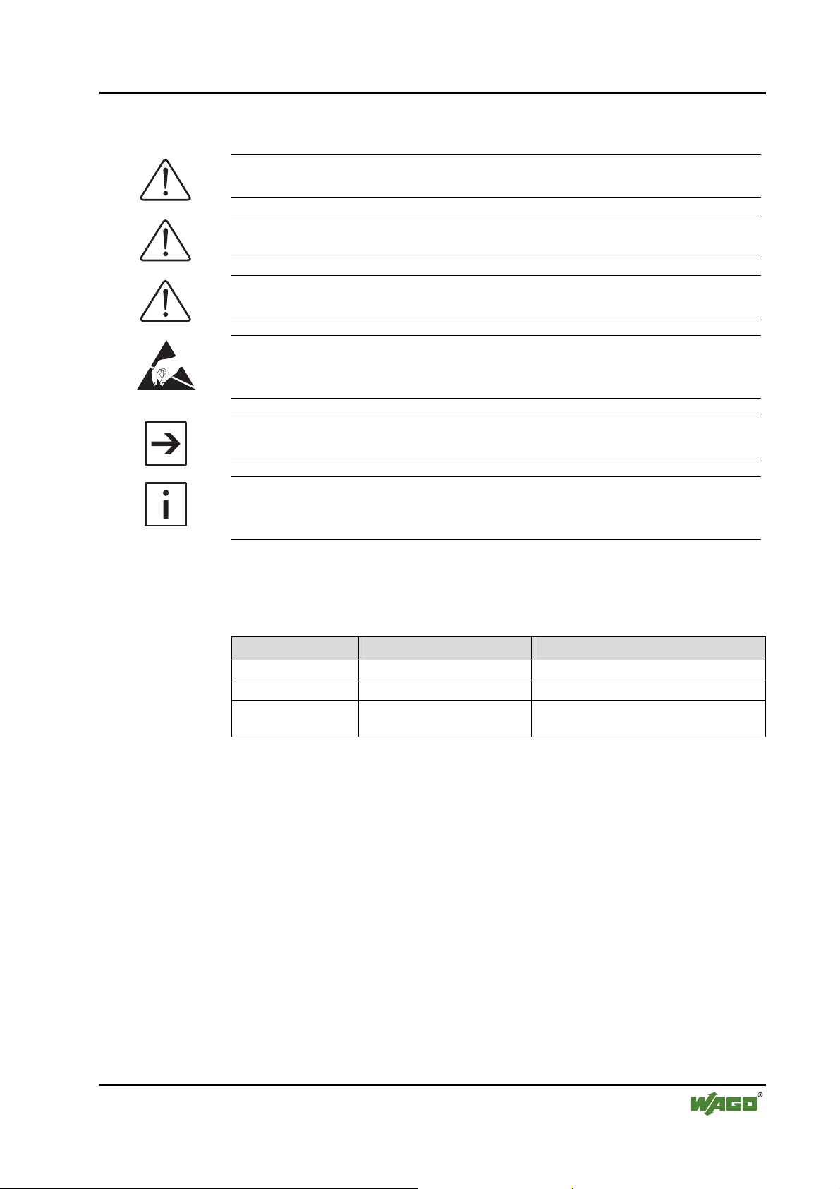
1.2 Symbols
Danger
Always abide by this information to protect persons from injury.
Warning
Always abide by this information to prevent damage to the device.
Attention
Marginal conditions must always be observed to ensure smooth operation.
ESD (Electrostatic Discharge)
Warning of damage to the components by electrostatic discharge. Observe
the precautionary measure for handling components at risk.
Note
Routines or advice for efficient use of the device and software optimization.
More information
References on additional literature, manuals, data sheets and INTERNET
pages
1.3 Number Notation
Number Code Example Note
Decimal 100 normal notation
Hexadecimal 0x64 C notation
Binary '100'
'0110.0100'
Within ',
Nibble separated with dots
WAGO-I/O-SYSTEM 750
I/O Modules
Page 6

6 • Important Comments
Safety Notes
1.4 Safety Notes
Attention
Switch off the system prior to working on bus modules!
In the event of deformed contacts, the module in question is to be replaced, as
its functionality can no longer be ensured on a long-term basis.
The components are not resistant against materials having seeping and insulating properties. Belonging to this group of materials is: e.g. aerosols, silicones, triglycerides (found in some hand creams).
If it cannot be ruled out that these materials appear in the component environment, then additional measures are to be taken:
- installation of the components into an appropriate enclosure
- handling of the components only with clean tools and materials.
Attention
Cleaning of soiled contacts may only be done with ethyl alcohol and leather
cloths. Thereby, the ESD information is to be regarded.
Do not use any contact spray. The spray may impair the functioning of the
contact area.
The WAGO-I/O-SYSTEM 750 and its components are an open system. It
must only be assembled in housings, cabinets or in electrical operation
rooms. Access must only be given via a key or tool to authorized qualified
personnel.
The relevant valid and applicable standards and guidelines concerning the
installation of switch boxes are to be observed.
ESD (Electrostatic Discharge)
The modules are equipped with electronic components that may be destroyed
by electrostatic discharge. When handling the modules, ensure that the environment (persons, workplace and packing) is well grounded. Avoid touching
conductive components, e.g. gold contacts.
1.5 Scope
This manual describes the Analog Input Module 750-491
1 AI DMS of the modular WAGO-I/O-SYSTEM 750.
Handling, assembly and start-up are described in the manual of the Fieldbus
Coupler. Therefore this documentation is valid only in the connection with the
appropriate manual.
WAGO-I/O-SYSTEM 750
I/O Modules
Page 7

750-491 [1 AI DMS] • 7 View
2 I/O Modules
2.1 Digital Output Modules
2.1.1 750-491 [1 AI DMS]
1-Channel Analog Input Module for Resistor Bridges (DMS)
2.1.1.1 View
13 14
Function U
Error U
+U
-U
D
D
D
D
A
B
+UD +UR
-UD -UR
0V 5V
C
D
Function U
Error U
Data contacts
+U
-U
ref
ref
+U
+U
+U
-U
V
ref
D
D
ref
ref
-U (0V)
(screen)
Fig. 1: 1-Channel Analog Input Module 750-491
2.1.1.2 Variations
Item-No. Designation Description
750-491 1 AI DMS 1-Channel Analog Input Module
750-491/000-001 1 AI DMS/65 ms 1-Channel Analog Input Module
2.1.1.3 Description
The analog input module enables the direct connection of a resistor measurement bridge. The brigde voltage UD and supply voltage U
digitised with a resolution of 16 bits.
V
Shield
SS
750-491
+U (5V)
V
Shield
(screen)
-U
ref
-U
V
The power supply Uv can be
obtained from the terminal or
can be feed in external. The
terminal supplies 5 V. The
maximum input voltage U
is limited to10 V.
ref
for Resistor Bridges (DMS)
for Resistor Bridges (DMS)
ref
of the brigde are
g049100e
The input channels for the resistor bridge are available as two 16 bit values for
further processing. The result of measurment can be calculated by the formula:
Measuring value = UD / U
WAGO-I/O-SYSTEM 750
I/O Modules
ref
Page 8

8 • 750-491 [1 AI DMS]
Display Elements
Due to the accurate measurement of supply voltage as well as bridge voltage
in one measurement transformer, long-term and temperature drift are compensated.
If the internal voltage supply (UV) is overloaded (I
power supply is necessary. (cf. chapter 2.1.1.9, “Connection examples”).
Any configuration of the input modules is possible when designing the
fieldbus node. Grouping of module types is not necessary
The voltage supply is done via system voltage.
Attention
This module has no power contacts. For field supply to downstream I/O
modules, a supply module will be needed.
The analog input module 750-491 and its variations can be used with all
couplers/controllers of the WAGO-I/O-SYSTEM 750 (except for the economy
types 750-320, -323, -324 and -327).
2.1.1.4 Display Elements
LED Channel Meaning State Function
A
green
> 20 mA), an external
load
No operational readiness or the
off
Function
U
D
internal data bus communication is
interrupted
Operational readiness and trouble-free
on
internal data bus communication
13 14
A
A
B
C
B
D
Fig. 2.1.1-1: Display
Elements
g045202x
B
red
C
D
Error
Brigde voltage U
on
range or broken wire
outside of the valid
D
No operational readiness or the
off Normal operation
C
green
off
Function
U
ref
internal data bus communication is
interrupted
Operational readiness and trouble-free
on
internal data bus communication
off Normal operation
D
red
Error
Voltage supply U
on
range
outside of the valid
ref
WAGO-I/O-SYSTEM 750
I/O Modules
Page 9

750-491 [1 AI DMS] • 9
Schematic Diagram
2.1.1.5 Schematic Diagram
+U
+U
-U
-U
Shield
(screen)
5
1
D
2
D
3
V
4
750-491
+U
ref
6
-U
ref
7
+U
V
8
+U
-U
-U
-U
+U
Shield
(screen)
D
ref
D
ref
V
V
+5V
A
D
Function U
Error U
Logic
D
ref
U
D
U
ref
Fig. 2.1.1-2: 2-Channel Analog Input Module 750-491
g049101e
WAGO-I/O-SYSTEM 750
I/O Modules
Page 10

10 • 750-491 [1 AI DMS]
Technical data
2.1.1.6 Technical data
Module Specific Data
Number of inputs 2, for one resistor bridge
Voltage supply via system voltage DC /DC
Current consumption
Signal voltage UD -15 mV ... +15 mV
Signal voltage U
Internal resistance UD > 1 MΩ
Internal resistance U
Voltage supply Uv DC 5 V, 20 mA
Resolution 16 bits
Conversion time 250 ms (750-491)
Measuring error
(total mearsuring range)
Filter 50 Hz (750-491)
Isolation 500 V (System/Supply)
Bit width 2 x 16 bits data
Dimensions (mm) W x H x L 12 x 64* x 100
(internal) 65 mA
typ.
-10 V ... +10 V
ref
> 200 kΩ
ref
65 ms (750-491/000-001)
<± 0.1 % (of the upper range value)
200 Hz (750-491/000-001)
2 x 8 bits control/status (option)
* from upper edge of 35 DIN rail
Weight ca. 60 g
Standards and Regulations (cf. Chapter 2.2 of the Coupler/Controller Manual)
EMC-Immunity to interference (CE) acc. to EN 50082-2 (96)
EMC-Emission of interference (CE) acc. to EN 50081-1 (93)
EMC-Immunity to interference
(Ship building)
EMC-Emission of interference
(Ship building)
Approvals (cf. Chapter 2.2 of the Coupler/Controller Manual)
Conformity Marking
acc. to Germanischer Lloyd (97)
acc. to Germanischer Lloyd (97)
More Information
Detailed references to the approvals are listed in the document "Overview
Approvals WAGO-I/O-SYSTEM 750", which You can find on the CD ROM
ELECTRONICC Tools and Docs (Item-No.: 0888-0412-0001-0101) or in the
Internet under:
www.wago.com
-> Service /Downloads /Documentation
/WAGO-I/O-SYSTEM 750/System Description/.
WAGO-I/O-SYSTEM 750
I/O Modules
Page 11

750-491 [1 AI DMS] • 11 Process Image
2.1.1.7 Process Image
The bridge voltage between +U
and -UD is output with a resolution of
D
500 nV/digit, so that 10 mV corresponds to an output value of 20000 in the
data bytes D0 and D1 of channel 1.
The supply voltage for the bridge is output with a resolution of 500 µV/digit,
so that 10 V corresponds to the output value 20000 in the data bytes D0 and
D1 of channel 2.
Process values of module 750-491
Numerical value Signal
voltage UD
±15 mV Output value
<ca.-15.5000 '0111.1111.1111.1111' 0x7FFF 32767 0x41 on
ca.-15.5000 '0000.0000.0000.0000' 0x0000 0 0x00 off
-15.0000 '1000.1010.1101.0000' 0x8AD0 -30000 0x00 off
-10.0000 '1011.0001.1110.0000' 0xB1E0 -20000 0x00 off
-5.0000 '1101.1000.1111.0000' 0xD8F0 -10000 0x00 off
-0.0005 '1111.1111.1111.1111' 0xFFFF -1 0x00 off
0.0000 '0000.0000.0000.0000' 0x0000 0 0x00 off
0.0005 '0000.0000.0000.0001' 0x0001 1 0x00 off
5.0000 '0010.0111.0001.0000' 0x2710 10000 0x00 off
10.0000 '0100.1110.0010.0000' 0x4E20 20000 0x00 off
15.0000 '0111.0101.0011.0000' 0x7530 30000 0x00 off
>ca.15.5000 '0111.1111.1111.1111' 0x7FFF 32767 0x41 on
Broken wire '0111.1111.1111.1111' 0x7FFF 32767 0x41 on
binary
hex. dec.
Status-
byte
hex.
LED
voltage U
<ca.–13.0000 '0111.1111.1111.1111' 0x7FFF 32767 0x41 on
>ca.13.0000 '0111.1111.1111.1111' 0x7FFF 32767 0x41 on
WAGO-I/O-SYSTEM 750
I/O Modules
Process values of module 750-491
Numerical value Signal
ref
±10 V Output value
-10.0000 '1011.0001.1110.0000' 0xB1E0 -20000 0x00 off
-5.0000 '1101.1000.1111.0000' 0xD8F0 -10000 0x00 off
-1.0000 '1111.1000.0011.0000' 0xF830 -2000 0x00 off
-0.0003 '1111.1111.1111.1111' 0xFFFF -1 0x00 off
0.0000 '0000.0000.0000.0000' 0x0000 0 0x00 off
0.0003 '0000.0000.0000.0001' 0x0001 1 0x00 off
1.0000 '0000.0111.1101.0000' 0x07D0 2000 0x00 off
5.0000 '0010.0111.0001.0000' 0x2710 10000 0x00 off
10.0000 '0100.1110.0010.0000' 0x4E20 20000 0x00 off
binary
hex. dec.
Status-
byte
hex.
LED
Page 12

12 • 750-491 [1 AI DMS]
Applicaton examples
2.1.1.8 Applicaton examples
A load cell was connected to the module in an experimental test bed.
The load cell was fed with the terminal's 5 V supply voltage (U
reference voltage (U
U
channels respectively.
D
Technical data for the load cell: 5 kg = 2 mV/V
The weight is calculated as follows: Weight = (U
2.1.1.9 Connection examples
The connected resistor measurement bridge can be supplied by the module via
the connections +U
voltage supply.
+U
+U
D
ref
-U
-U
D
ref
+U
-U
V
V
), while the
V
) and the bridge voltage were captured with the U
ref
/ 2 mV) / (U
D
and -UV (see following illustration) or by an external
V
/ 1 V) * 5kg
ref
ref
and
SS
If the resistor measurement bridge is supplied by an external voltage supply, a
common ground (earth) potential must be made by bridging the -U
tion of the module to the externally -U
+U
+U
D
ref
-U
-U
D
ref
-U
+U
V
V
SS
+U
-U
V extern
V extern
(see illustration down).
V extern
connec-
V
Fig. 2.1.1-3: Connection of a Resistor Measurement Bridge with external Supply
g049105x
WAGO-I/O-SYSTEM 750
I/O Modules
Page 13

750-491 [1 AI DMS] • 13
Connection examples
WAGO-I/O-SYSTEM 750
I/O Modules
Page 14

WAGO Kontakttechnik GmbH & Co. KG
Postfach 2880 • D-32385 Minden
Hansastraße 27 • D-32423 Minden
Phone: 05 71/8 87 – 0
Fax: 05 71/8 87 – 1 69
E-Mail: info@wago.com
Internet: http://www.wago.com
 Loading...