

Fieldbus Independent
I/O Modules
2 AI 4-20 mA, Differential Inputs
750-454
Manual
Version 1.0.2

ii • General
WAGO-I/O-SYSTEM 750
I/O Modules
Copyright © 2006 by WAGO Kontakttechnik GmbH & Co. KG
All rights reserved.
WAGO Kontakttechnik GmbH & Co. KG
Hansastraße 27
D-32423 Minden
Phone: +49 (0) 571/8 87 – 0
Fax: +49 (0) 571/8 87 – 1 69
E-Mail: info@wago.com
Web: http://www.wago.com
Technical Support
Phone: +49 (0) 571/8 87 – 5 55
Fax: +49 (0) 571/8 87 – 85 55
E-Mail: support@wago.com
Every conceivable measure has been taken to ensure the correctness and completeness of this documentation. However, as errors can never be fully excluded, we would appreciate any information or ideas at any time.
E-Mail: documentation@wago.com
We wish to point out that the software and hardware terms as well as the
trademarks of companies used and/or mentioned in the present manual are
generally trademark or patent protected.

Content • iii
WAGO-I/O-SYSTEM 750
I/O Modules
Content
1 Important Comments .................................................................................4
1.1 Legal Principles........................................................................................4
1.1.1 Copyright............................................................................................. 4
1.1.2 Personnel Qualification ....................................................................... 4
1.1.3 Intended Use........................................................................................ 4
1.2 Symbols.................................................................................................... 5
1.3 Number Notation......................................................................................5
1.4 Safety Notes .............................................................................................6
1.5 Scope ........................................................................................................ 6
2 I/O Modules ................................................................................................. 7
2.1 Digital Output Modules............................................................................ 7
2.1.1 750-454 [2 AI 4-20 mA, Differential Inputs]...................................... 7
2.1.1.1 View................................................................................................7
2.1.1.2 Variations........................................................................................7
2.1.1.3 Description......................................................................................8
2.1.1.4 Display Elements ............................................................................9
2.1.1.5 Schematic Diagram.........................................................................9
2.1.1.6 Technical Data ..............................................................................10
2.1.1.7 Process Image ............................................................................... 11
2.1.1.7.1 Standard Data Format ...................................................................12
2.1.1.7.2 Special Data Format...................................................................... 13

4 • Important Comments
Legal Principles
WAGO-I/O-SYSTEM 750
I/O Modules
1 Important Comments
To ensure fast installation and start-up of the units described in this manual,
we strongly recommend that the following information and explanations are
carefully read and abided by.
1.1 Legal Principles
1.1.1 Copyright
This manual is copyrighted, together with all figures and illustrations
contained therein. Any use of this manual which infringes the copyright
provisions stipulated herein, is not permitted. Reproduction, translation and
electronic and photo-technical archiving and amendments require the written
consent of WAGO Kontakttechnik GmbH & Co. KG. Non-observance will
entail the right of claims for damages.
WAGO Kontakttechnik GmbH & Co. KG reserves the right to perform
modifications allowed by technical progress. In case of grant of a patent or
legal protection of utility patents all rights are reserved by WAGO
Kontakttechnik GmbH & Co. KG. Products of other manufacturers are always
named without referring to patent rights. The existence of such rights can
therefore not be ruled out.
1.1.2 Personnel Qualification
The use of the product detailed in this manual is exclusively geared to
specialists having qualifications in PLC programming, electrical specialists or
persons instructed by electrical specialists who are also familiar with the valid
standards. WAGO Kontakttechnik GmbH & Co. KG declines all liability
resulting from improper action and damage to WAGO products and third party
products due to non-observance of the information contained in this manual.
1.1.3 Intended Use
For each individual application, the components supplied are to work with a
dedicated hardware and software configuration. Modifications are only
permitted within the framework of the possibilities documented in the
manuals. All other changes to the hardware and/or software and the nonconforming use of the components entail the exclusion of liability on part of
WAGO Kontakttechnik GmbH & Co. KG.
Please direct any requirements pertaining to a modified and/or new hardware
or software configuration directly to WAGO Kontakttechnik GmbH & Co.
KG.
Important Comments • 5
Symbols
WAGO-I/O-SYSTEM 750
I/O Modules
1.2 Symbols
Danger
Always abide by this information to protect persons from injury.
Warning
Always abide by this information to prevent damage to the device.
Attention
Marginal conditions must always be observed to ensure smooth operation.
ESD (Electrostatic Discharge)
Warning of damage to the components by electrostatic discharge. Observe
the precautionary measure for handling components at risk.
Note
Routines or advice for efficient use of the device and software optimization.
More information
References on additional literature, manuals, data sheets and INTERNET
pages
1.3 Number Notation
Number Code Example Note
Decimal 100 normal notation
Hexadecimal 0x64 C notation
Binary '100'
'0110.0100'
Within ',
Nibble separated with dots

6 • Important Comments
Safety Notes
WAGO-I/O-SYSTEM 750
I/O Modules
1.4 Safety Notes
Warning
Switch off the system prior to working on bus modules!
In the event of deformed contacts, the module in question is to be replaced, as
its functionality can no longer be ensured on a long-term basis.
The components are not resistant against materials having seeping and
insulating properties. Belonging to this group of materials is: e.g. aerosols,
silicones, triglycerides (found in some hand creams).
If it cannot be ruled out that these materials appear in the component
environment, then additional measures are to be taken:
- installation of the components into an appropriate enclosure
- handling of the components only with clean tools and materials.
Attention
Cleaning of soiled contacts may only be done with ethyl alcohol and leather
cloths. Thereby, the ESD information is to be regarded.
Do not use any contact spray. The spray may impair the functioning of the
contact area.
The WAGO-I/O-SYSTEM 750 and its components are an open system. It
must only be assembled in housings, cabinets or in electrical operation
rooms. Access must only be given via a key or tool to authorized qualified
personnel.
The relevant valid and applicable standards and guidelines concerning the
installation of switch boxes are to be observed.
ESD (Electrostatic Discharge)
The modules are equipped with electronic components that may be destroyed
by electrostatic discharge. When handling the modules, ensure that the
environment (persons, workplace and packing) is well grounded. Avoid
touching conductive components, e.g. gold contacts.
1.5 Scope
This manual describes the Analog Input Module 750-454
2 AI 4-20 mA, Differential Inputs of the modular WAGO-I/O-SYSTEM 750.
Handling, assembly and start-up are described in the manual of the Fieldbus
Coupler. Therefore this documentation is valid only in the connection with the
appropriate manual.

750-454 [2 AI 4-20 mA, Differential Inputs] • 7
View
WAGO-I/O-SYSTEM 750
I/O Modules
2 I/O Modules
2.1 Digital Output Modules
2.1.1 750-454 [2 AI 4-20 mA, Differential Inputs]
2-Channel Analog Input Module (4-20mA, differential inputs)
2.1.1.1 View
+E1 +E2
13 14
C
D
B
A
-E1 -E2
MM
SS
750-454
+AI 2
Data contacts
Function AI 2
-AI 2
Common
(ground)
Common
(ground)
Function AI 1
+AI 1
-AI 1
Error AI 2
Error AI 1
Shield
(screen)
Shield
(screen)
Fig. 2.1.1-1: 2-Channel Analog Input Module 750-454 g045400e
2.1.1.2 Variations
Item-No. Designation Description
750-454 2 AI (4-20mA)
differential inputs
2-Channel Analog Input Module, 4-20mA,
differential inputs
750-454/000-001 2 AI (4-20mA)
differential inputs,
RC low-pass
2-Channel Analog Input Module, 4-20mA,
differential inputs with RC low-pass
750-454/000-002 2 AI (4-20mA)
differential inputs,
special data format
2-Channel Analog Input Module, 4-20mA,
differential inputs with special data format
750-454/000-200 2 AI (4-20mA)
differential inputs
with Siemens
(S5-FB 250)
2-Channel Analog Input Module, 4-20mA,
differential inputs, adapted data format for
S5-control systems with the use of function
block FB 250

8 • 750-454 [2 AI 4-20 mA, Differential Inputs]
Description
WAGO-I/O-SYSTEM 750
I/O Modules
2.1.1.3 Description
The analog input module and its variations receives signals with standardized
values of 4-20 mA.
The module has two differential input channels and can receive differential
signals via the connections +AI 1 and -AI 1 or +AI 2 and -AI 2.
The input channels of a module have a common ground and a shield (screen)
connection (S). The Shield (sreen) is directly connected to the DIN rail. A
capacitive connection is made automatically when snapped onto the DIN rail.
The input signal of each channel is electrically isolated and will be transmitted
with a resolution of 12 bits.
The operational readiness and trouble-free internal data bus communication of
the channels are indicated via a green Function LED. Broken wire, overrange
or underflow of the measuring range is indicated via a red error LED.
Any configuration of the input modules is possible when designing the
fieldbus node. Grouping of module types is not necessary.
The voltage supply is done via system voltage.
Attention
This module has no power contacts. For field supply to downstream I/O
modules, a supply module will be needed.
The analog input module 750-454 and its variations can be used with all
couplers/controllers of the WAGO-I/O-SYSTEM 750 (except for the economy
types 750-320, -323, -324 and -327).
750-454 [2 AI 4-20 mA, Differential Inputs] • 9
Display Elements
WAGO-I/O-SYSTEM 750
I/O Modules
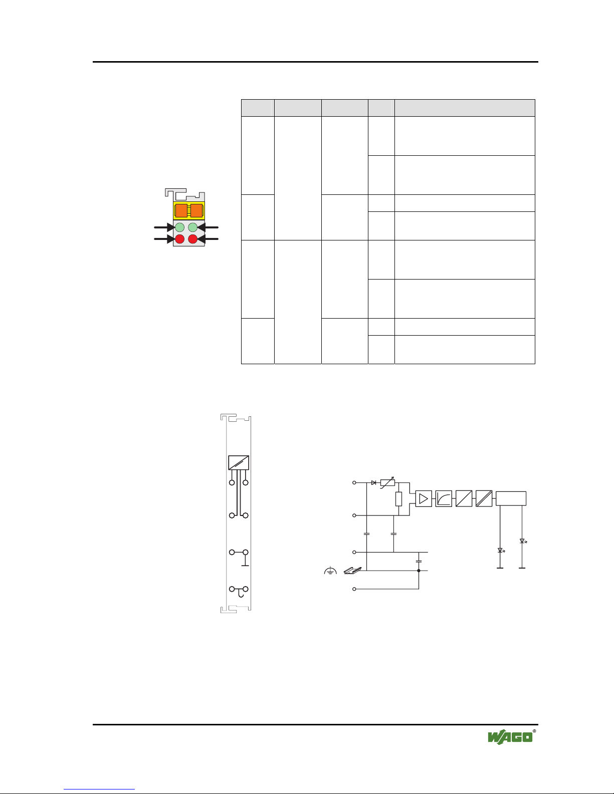
2.1.1.4 Display Elements
LED Channel Meaning State Function
off
No operational readiness or the
internal data bus communication is
interrupted
A
green
Function
AI 1
on
Operational readiness and troublefree internal data bus
communication
off Normal operation
B
red
1
Error
AI 1
on
Broken wire, overrange/underflow
of the admissible measuring range
off
No operational readiness or the
internal data bus communication is
interrupted
C
green
Function
AI 2
on
Operational readiness and troublefree internal data bus
communication
off Normal operation
13 14
C
D
B
A
D
C
B
A
Fig. 2.1.1-2: Display
Elements
g041802x
D
red
2
Error
AI 2
on
Broken wire, overrange/underflow
of the admissible measuring range
2.1.1.5 Schematic Diagram
Common
(ground)
Common
(ground)
Shield
(screen)
+AI 1
+AI 2
-AI 2
-AI 1
+Al
-AI
10nF
270pF 270pF
A
D
Logic
I
Function
Error
Shield
(screen)
1
2
3
4
5
6
7
8
750-454
Fig. 2.1.1-3: 2-Channel Analog Input Module 750-454 g045401e

10 • 750-454 [2 AI 4-20 mA, Differential Inputs]
Technical Data
WAGO-I/O-SYSTEM 750
I/O Modules
2.1.1.6 Technical Data
Module Specific Data
Number of inputs 2
Voltage supply via system voltage DC /DC
Current consumption
typ.
(internal) 70 mA
Common mode voltage
max.
35 V
Signal current 4 mA... 20 mA
Input resistance
<220 Ω at 20 mA
Resolution 12 bits
Conversion time
typ.
2 ms
Measuring error
25°C
<± 0,2 % of full scale value
Temperature coefficient
<± 0,01 % /K of full scale value
Isolation 500 V (Field/System)
Bit width 2 x 16 bits data
2 x 8 bits control/status (option)
Dimensions (mm) W x H x L 12 x 64* x 100
* from upper edge of 35 DIN rail
Weight ca. 55 g
Standards and Regulations (cf. Chapter 2.2 of the Coupler/Controller Manual)
EMC-Immunity to interference (CE) acc. to EN 50082-2 (96)
EMC-Emission of interference (CE) acc. to EN 50081-1 (93)
EMC-Immunity to interference
(Ship building)
acc. to Germanischer Lloyd (97)
EMC-Emission of interference
(Ship building)
acc. to Germanischer Lloyd (97)

750-454 [2 AI 4-20 mA, Differential Inputs] • 11
Process Image
WAGO-I/O-SYSTEM 750
I/O Modules
Approvals (cf. Chapter 2.2 of the Coupler/Controller Manual)
CULUS
(UL508)
ABS (American Bureau of Shipping)
BV (Bureau Veritas)
DNV (Det Norske Veritas) Cl. B
GL (Germanischer Lloyd) Cat. A, B, C, D
KR (Korean Register of Shipping)
LR (Lloyd's Register)
Env. 1, 2, 3, 4
(only for 750-454, /000-200)
NKK (Nippon Kaiji Kyokai)
RINA (Registro Italiano Navale) (only for 750-454)
CULUS
(UL1604) Class I Div2 ABCD T4A
KEMA II 3 G EEx nA II T4
Conformity Marking
More Information
Detailed references to the approvals are listed in the document "Overview
Approvals WAGO-I/O-SYSTEM 750", which you can find on the CD ROM
ELECTRONICC Tools and Docs (Item-No.: 0888-0412)
or in the internet under:
www.wago.com ! Documentation ! WAGO-I/O-SYSTEM 750 !
System Description
2.1.1.7 Process Image
The analog input module 750-454 transmits 16-bit measured values and
8 optional status bits per channel.
The digitalized measured value is transmitted in a data word (16 bits) as input
byte 0 (low) and input byte 1 (high) into the process image of the coupler /
controller.
This value is represented with a 12 bit resolution on bit B3 ... B14.
From the manufacturing number |32|02|XX|XX| onwards, the status
information included in the three least significant bits (B0 ... B2) can be
parsed in the event of an error
Bit B0 = 1 is set when the range of measurement is overranged.
Bit B0 and B1 = 1 are set in case of measurement range underflow or broken
wire. For modules having a previous manufacturing number, the last 3 bits are
not parsed.

12 • 750-454 [2 AI 4-20 mA, Differential Inputs]
Process Image
WAGO-I/O-SYSTEM 750
I/O Modules
The manufacturing number is part of the lateral marking on the module
enclosure.
Some fieldbus systems can process input channel status information by means
of a status byte.
This status byte can be displayed via the starting tool WAGO-I/O-CHECK 2.
However, processing via the coupler / controller is optional, which means that
accessing or parsing the status information depends on the fieldbus system.
Attention
The representation of the process data of some I/O modules or their variations
in the process image depends on the fieldbus coupler/-controller used. Please
take this information as well as the particular design of the respective
control/status bytes from the section "Fieldbus Specific Design of the Process
Data" included in the description concerning the process image of the
corresponding coupler/controller.
2.1.1.7.1 Standard Data Format
For the standard module 750-454 and the variations 750-454/000-001 the
input current ranging from 4 mA to 20 mA is scaled on the numerical values
ranging from 0x0000 bis 0x7FF9.
Process values of module 750-454, 750-454/000-001
numerical value Input current
binary
Status-
byte
LED
Error
4 mA - 20 mA Measured value *) X F Ü
hex. dec.
hex. AI 1, 2
<0 not possible (Reverse voltage protection)
<4 - ∆**)
'0000.0000.0000.0 011' 0x0003 3 0x41 on
<4 '0000.0000.0000.0 000' 0x0000 0 0x00 off
4 '0000.0000.0000.0 000' 0x0000 0 0x00 off
6 '0001.0000.0000.0 000' 0x1000 4096 0x00 off
8 '0010.0000.0000.0 000' 0x2000 8192 0x00 off
10 '0011.0000.0000.0 000' 0x3000 12288 0x00 off
12 '0100.0000.0000.0 000' 0x4000 16384 0x00 off
14 '0101.0000.0000.0 000' 0x5000 20480 0x00 off
16 '0110.0000.0000.0 000' 0x6000 24576 0x00 off
18 '0111.0000.0000.0 000' 0x7000 28672 0x00 off
20 '0111.1111.1111.1 000' 0x7FF8 32760 0x00 off
>20 '0111.1111.1111.1 001' 0x7FF9 32761 0x42 off
>20 + ∆**)
'0111.1111.1111.1 001' 0x7FF9 32761 0x42 on
*) status bits: X = not used, F = short-circuit, Ü = oversize
**
)
∆ = 0,1 ... 2,0 mA

750-454 [2 AI 4-20 mA, Differential Inputs] • 13
Process Image
WAGO-I/O-SYSTEM 750
I/O Modules
2.1.1.7.2 Special Data Format
To digitalize the measurement value, the variation 750-454/000-002 uses
another resolution as the standard module.
For this variation, the input current ranging from 4 mA to 20 mA is scaled on
the numerical values ranging from 0x0000 to 0x0F99.
Process values of module 750-454/000-002
numerical value Input current
binary
Status-
byte
LED
Error
4 mA - 20 mA Measured value *) X F Ü
hex. dec.
hex. AI 1, 2
<0 not possible (Reverse voltage protection)
<4 - ∆**)
'0000.0000.0000.0 011' 0x0003 3 0x41 on
<4 '0000.0000.0000.0 000' 0x0000 0 0x00 off
4 '0000.0000.0000.0 000' 0x0000 0 0x00 off
6 '0000.0001.1111.0 000' 0x01F0 500 0x00 off
8 '0000.0011.1110.1 000' 0x03E8 1000 0x00 off
10 '0000.0101.1101.1 000' 0x05D8 1500 0x00 off
12 '0000.0111.1101.0 000' 0x07D0 2000 0x00 off
14 '0000.1001.1100.0 000' 0x09C0 2500 0x00 off
16 '0000.1011.1011.1 000' 0x0BB8 3000 0x00 off
18 '0000.1101.1010.1 000' 0x0DA8 3500 0x00 off
20 '0000.1111.1001.1 000' 0x0F98 3992 0x00 off
>20 '0000.1111.1001.1 001' 0x0F99 3993 0x42 off
>20 + ∆**)
'0000.1111.1001.1 001' 0x0F99 3993 0x42 on
*) status bits: X = not used, F = short-circuit, Ü = oversize
**
)
∆ = 0,1 ... 2,0 mA

14 • 750-454 [2 AI 4-20 mA, Differential Inputs]
Process Image
WAGO-I/O-SYSTEM 750
I/O Modules

750-454 [2 AI 4-20 mA, Differential Inputs] • 15
Process Image
WAGO-I/O-SYSTEM 750
I/O Modules
To digitalize the measurement value, the variation 750-454/000-200 uses a
format adapted for the S5 control systems using FB 250.
For this variation, the input current ranging from 4 to 20 mA is scaled on the
numerical values ranging from 0x1000 to 0x5001.
Process values of module 750-454/000-200
numerical value Input current
binary
Status-
byte
LED
Error
0 mA - 20 mA Measured value *) X F Ü
hex. dec.
hex. AI 1, 2
<0 not possible (Reverse voltage protection)
<4 - ∆**)
'0001.0000.0000.0 011' 0x1003 4099 0x41 on
<4 '0001.0000.0000.0 000' 0x1000 4096 0x00 off
4 '0001.0000.0000.0 000' 0x1000 4096 0x00 off
6 '0001.1000.0000.0 000' 0x1800 6144 0x00 off
8 '0010.0000.0000.0 000' 0x2000 8192 0x00 off
10 '0010.1000.0000.0 000' 0x2800 10240 0x00 off
12 '0011.0000.0000.0 000' 0x3000 12288 0x00 off
14 '0011.1000.0000.0 000' 0x3800 14336 0x00 off
16 '0100.0000.0000.0 000' 0x4000 16384 0x00 off
18 '0100.1000.0000.0 000' 0x4800 18432 0x00 off
20 '0101.0000.0000.0 000' 0x5000 20480 0x00 off
>20 '0101.0000.0000.0 001' 0x5001 20481 0x42 off
>20 + ∆**)
'0101.0000.0000.0 001' 0x5001 20481 0x42 on
*) status bits: X = not used, F = short-circuit, Ü = oversize
**
)
∆ = 0,1 ... 2,0 mA

WAGO Kontakttechnik GmbH & Co. KG
Postfach 2880 • D-32385 Minden
Hansastraße 27 • D-32423 Minden
Phone: 05 71/8 87 – 0
Fax: 05 71/8 87 – 1 69
E-Mail: info@wago.com
Internet: http://www.wago.com
 Loading...