

WAGO 750-402, 750-402/025-000, WAGO-I/O-SYSTEM 750 Series, 750-406, 750-430 User Manual
...Page 1
Pos: 2 /Dokumentation allgemein/Einband/Einband Han dbuch - Deckblatt ohne Varia ntenfeld (S tandard) @ 9\mod_1285229289866_0.docx @ 64941 @ @ 1
Manual
WAGO-I/O-SYSTEM 750
4-Channel Digital Input Module 24 V DC, 2- to 3-
Pos: 3 /Alle Serien (Al lgemein e Module)/H inweise z ur Dokumen tation/Im pressum für Standar dhandbüc her - allg. A ng a be n, A ns c hriften, Tel ef onnummer n und E-Mail-A dr es sen @ 3\mod_1219151118203_21.docx @ 21060 @ @ 1
4DI 24V DC 3.0ms
750-402(/xxx-xxx)
conductor conne ction; high-side switching
Version 1.1.0
Page 2

2 WAGO-I/O-SYSTEM 750
750-402 4DI 24V DC 3.0ms
© 2013 by WAGO Kontakttechnik GmbH & Co. KG
All rights reserved.
WAGO Kontakttechnik GmbH & Co. KG
Hansastraße 27
D-32423 Minden
Phone: +49 (0) 571/8 87 – 0
Fax: +49 (0) 571/8 87 – 1 69
E-Mail: info@wago.com
Web: http://www.wago.com
=== Ende der Liste für Textmar ke Einband _vorne ===
Technical Support
Phone: +49 (0) 571/8 87 – 5 55
Fax: +49 (0) 571/8 87 – 85 55
E-Mail: support@wago.com
Every conceivable measure has been taken to ensure the accuracy and
completeness of this documentation. However, as errors can never be fully
excluded, we always appreciate any information or suggestions for improving the
documentation.
E-Mail: documentation@wago.com
We wish to point out that the software and hardware terms as well as the
trademarks of companies used and/or mentioned in the present manual are
generally protected by trademark or patent.
Manual
Version 1.1.0
Page 3

WAGO-I/O-SYSTEM 750 Table of Contents 3
750-402 4DI 24V DC 3.0ms
Pos: 5 /Do kumentation allgemei n/Verzeic hnisse/Inh altsverz eichnis - Üb er s chr i f t oG und Verzei chnis @ 3\mod_1219151230875_21.docx @ 21063 @ @ 1
Table of Contents
Table of Contents ................................................................................................... 3
1 Notes about this Documentation ................................................................. 5
1.1 Validity of this Documentation ................................................................. 5
1.2 Copyright ................................................................................................... 5
1.3 Symbols ..................................................................................................... 6
1.4 Number Notation ....................................................................................... 8
1.5 Font Conventions ...................................................................................... 8
2 Important Notes ........................................................................................... 9
2.1 Legal Bases ............................................................................................... 9
2.1.1 Subject to Changes ............................................................................... 9
2.1.2 Personnel Qualifications ....................................................................... 9
2.1.3 Use of the 750 Series in Compliance with Underlying Provisions ...... 9
2.1.4 Technical Condition of Specified Devices ......................................... 10
2.2 Safety Advice (Precautions) .................................................................... 11
3 Device Description ..................................................................................... 13
3.1 View ........................................................................................................ 15
3.2 Connectors ............................................................................................... 16
3.2.1 Data Contacts/Internal Bus ................................................................. 16
3.2.2 Power Jumper Contacts/Field Supply ................................................ 17
3.2.3 CAGE CLAMP® Connectors ............................................................. 18
3.3 Display Elements .................................................................................... 19
3.4 Schematic Diagram ................................................................................. 20
3.5 Technical Data ........................................................................................ 21
3.5.1 Device data ......................................................................................... 21
3.5.2 Supply ................................................................................................. 21
3.5.3 Communication .................................................................................. 21
3.5.4 Inputs .................................................................................................. 21
3.5.5 Connection Type ................................................................................ 22
3.5.6 Climatic Environmental Conditions ................................................... 22
3.6 Approvals ................................................................................................ 23
3.7 Standards and Guidelines ........................................................................ 25
4 Process Image ............................................................................................. 26
5 Mounting ..................................................................................................... 27
5.1 Mounting Sequence ................................................................................. 27
5.2 Inserting and Removing Devices ............................................................ 28
5.2.1 Inserting I/O Module .......................................................................... 28
5.2.2 Removing the I/O Module .................................................................. 29
6 Connect Devices ......................................................................................... 30
6.1 Connecting a Conductor to the CAGE CLAMP® ................................... 30
6.2 Connection Examples .............................................................................. 31
6.2.1 2-Conductor Connection .................................................................... 31
6.2.2 3-Conductor Connection .................................................................... 31
7 Use in Hazardous Environments .............................................................. 32
Manual
Version 1.1.0
Page 4

4 Table of Contents WAGO-I/O-SYSTEM 750
750-402 4DI 24V DC 3.0ms
7.1 Marking Configuration Examples ........................................................... 33
7.1.1 Marking for Europe according to ATEX and IEC-Ex ........................ 33
7.1.2 Marking for America according to NEC 500 ..................................... 38
7.2 Installation Regulations ........................................................................... 39
7.2.1 Special conditions for safe use (ATEX Certificate TÜV 07 ATEX
554086 X) ........................................................................................... 40
7.2.2 Special conditions for safe use (ATEX Certificate TÜV 12 ATEX
106032 X) ........................................................................................... 41
7.2.3 Special conditions for safe use (IEC-Ex Certificate TUN 09.0001 X)42
7.2.4 Special conditions for safe use (IEC-Ex Certificate IECEx TUN
12.0039 X) .......................................................................................... 43
7.2.5 ANSI/ISA 12.12.01 ............................................................................ 44
List of Figures ...................................................................................................... 45
List of Tables ........................................................................................................ 46
=== Ende der Liste für Textmar ke Verzeich nis_vorne ===
Manual
Version 1.1.0
Page 5

WAGO-I/O-SYSTEM 750 Notes about this Documentation 5
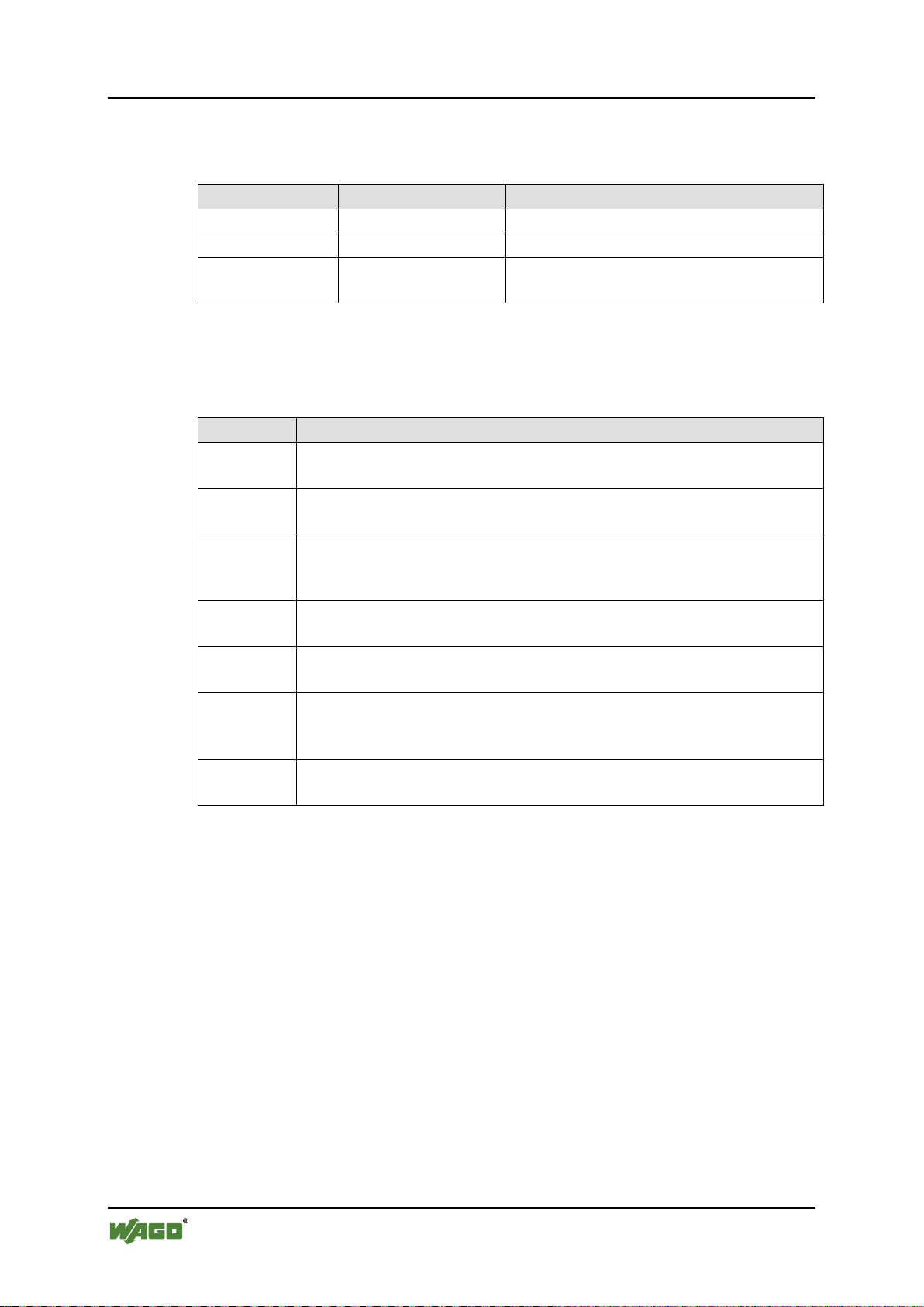
Table 1: Variants
Item Number/Variant
Designation
750-402
4DI 24V DC 3.0ms
750-402/025-000
4DI 24V DC 3.0ms/T
750-402 4DI 24V DC 3.0ms
Pos: 7 /Alle Serien (Al lgemein e Module)/Ü berschri ften für all e Serien/Hi nweis z ur Dokumen tation/Hin weise zur D okument ation - Über schrift 1 @ 4\mod_1237987661750_21.doc x @ 29029 @ 1 @ 1
1 Notes about this Documentation
Pos: 8 /Alle Serien (Al lgemein e Module)/H inweise z ur Dokumen tation/Hi nweise/Hi nweis: Do kumentatio n aufbew ahren @ 4\mod_1237987339812_21.docx @ 29026 @ @ 1
Keep this documentation!
The operating instructions are part of the product and shall be kept for the entire
lifetime of the device. They shall be transferred to each subsequent owner or user
of the device. Care must also be taken to ensure that any supplement to these
instructions are included, if applicable.
Pos: 9 /Alle Serien (Al lgemein e Module)/Ü berschri ften für all e Serien/H inweis z ur Dokumen tation/Gül tigkeits bereich - Üb er s c hrift 2 @ 12\mod_1338912448776_21.docx @ 96469 @ 2 @ 1
1.1 Validity of this Documentation
Pos: 10 /Ser ie 750 ( WAGO-I/O-SYST EM)/Hin weise zur D okumentati on/Gültig keitsberei ch Dokum entation B usklemme 750-xxxx, St an d ardversio n un d a ufgelistet e V arianten @ 14 \ mod_1358944038682_21.docx @ 109354 @ @ 1
This documentation is only applicable to the I/O module 750-402 (4DI 24V DC
3.0ms) of the WAGO-I/O-SYSTEM 750 series and the variants listed in the table
below.
Pos: 11 /Ser ie 750 ( WAGO-I/O-SYST EM)/Hin weise zur D okumentat ion/Varia ntenliste n/Variant enliste - 750-xxx - St andardvers ion und V ariante /0 25-000 (erw eiterter T emperatur bereich) @ 9\mod_1281521920414_21. doc x @ 63093 @ @ 1
Pos: 12 /Ser ie 750 ( WAGO-I/O-SYST EM)/Hin weise zur D okumentati on/Hinwei se/Achtu ng: Hinweis zur Doku mentation Busklemme n 750-xxxx @ 4\mod_1237986979656_21.docx @ 29023 @ @ 1
The I/O module 750-402 shall only be installed and operated according to the
instructions in this manual and in the manual for the used fieldbus
coupler/controller.
Consider power layout of the WAGO-I/O-SYSTEM 750!
In addition to these operating instructions, you will also need the manual for the
used fieldbus coupler/controller, which can be downloaded at www.wago.com.
There, you can obtain important information including information on electrical
isolation, system power and supply specifications.
Pos: 13.1 /Al le Seri en (Allgemei ne Modul e)/Hinweis e zur Dok umentation /Urhebers chutz aus führlich @ 4\mod_1235565145234_21.docx @ 27691 @ 2 @ 1
1.2 Copyright
Pos: 13.2 /Dokumentation allgemein/Glieder ungselemente/---Seitenwechsel--- @ 3\mod_1221108045078_0.docx @ 21810 @ @ 1
Manual
Version 1.1.0
This Manual, including all figures and illustrations, is copyright-protected. Any
further use of this Manual by third parties that violate pertinent copyright
provisions is prohibited. Reproduction, translation, electronic and phototechnical
filing/archiving (e.g., photocopying) as well as any amendments require the
written consent of WAGO Kontakttechnik GmbH & Co. KG, Minden, Germany.
Non-observance will involve the right to assert damage claims.
Page 6
6 Notes about this Documentation WAGO-I/O-SYSTEM 750
750-402 4DI 24V DC 3.0ms
Pos: 13.3 /Al le Seri en (Allgemei ne Modul e)/Überschr iften für alle Seri en/Hinweis zur Dok umentation /Symbole - Ü berschrif t 2 @ 13\mod_1351068042408_21.docx @ 105270 @ 2 @ 1
1.3 Symbols
Pos: 13.4.1 /Alle Ser ien (Allg emeine Mo dule)/Wic htige Erlä uterungen/ Sicherhei ts- und sonstige Hinweise/G efahr/Gefahr: _Warnung vor Personenschäden allgemein_ - Erläuterung @ 13\mod_1343309450020_21.doc x @ 101029 @ @ 1
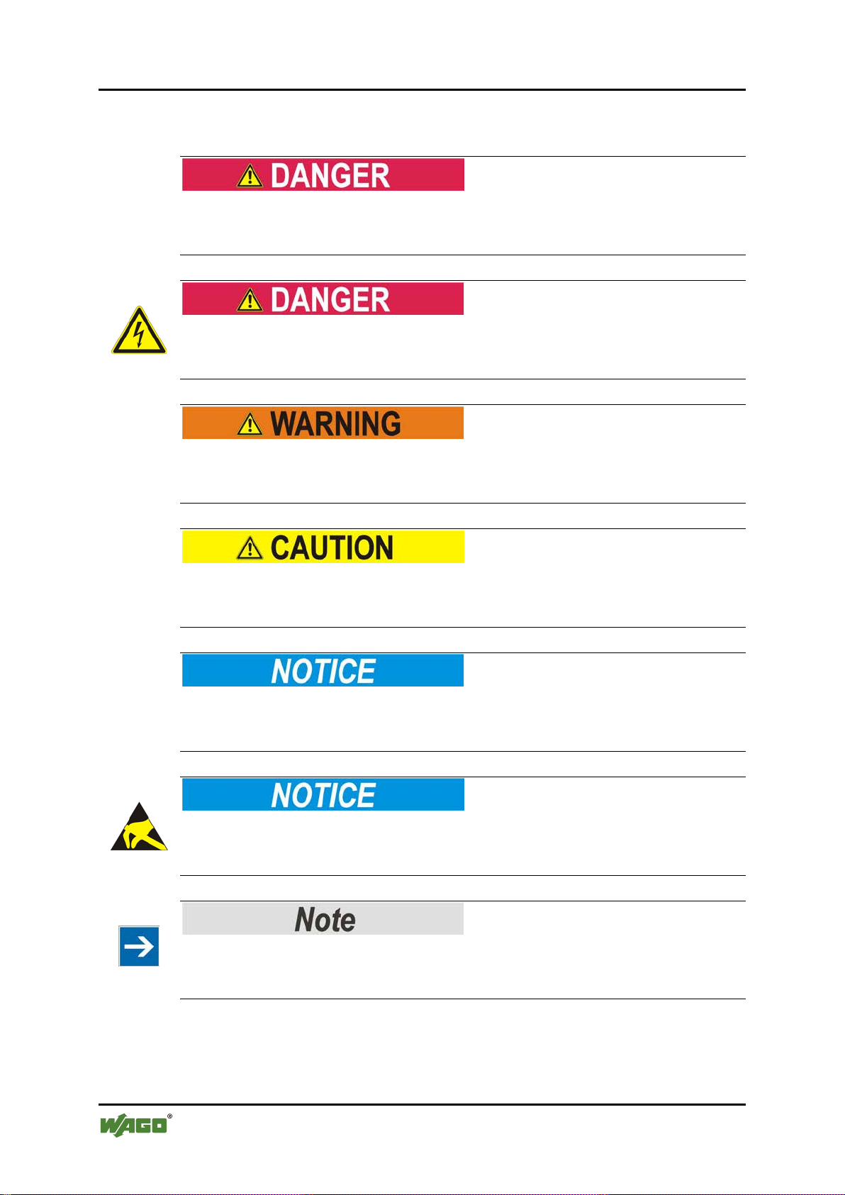
Personal Injury!
Indicates a high-risk, imminently hazardous situation which, if not avoided, will
result in death or serious injury.
Pos: 13.4.2 /All e Serien (All g emeine Mod ul e) / Wichtige Er lä uterunge n/ Sicherheit s- und sonsti g e Hin weise/Ge f a hr /G efahr: _War nung vor Pers o n en schäden dur c h el e ktrische n Str o m_ - Erläuterung @ 13\mod_1343309694914_21.docx @ 101030 @ @ 1
Personal Injury Caused by Electric Current!
Indicates a high-risk, imminently hazardous situation which, if not avoided, will
result in death or serious injury.
Pos: 13.4.3 /All e Serien (All g emeine Mod ul e) / Wichtige Er lä uterunge n/ Sicherheit s- und sons tige Hinwei se/Warnung /Warnung : _Warnu ng vor Per sonenschäd en allgem ein_ - Erläuterung @ 13\mod_1343309877041_21.docx @ 101035 @ @ 1
Personal Injury!
Indicates a moderate-risk, potentially hazardous situation which, if not avoided,
could result in death or serious injury.
Pos: 13.4.4 /All e Serien (All g emeine Mod ul e) / Wichtige Er lä uterunge n/ Sicherheit s- und sons tige Hinwei se/Vorsic ht/Vorsic ht: _Warnu ng vor Per sonenschä den allge mein_ - Erl äuterung @ 13\mod_1343310028762_21.docx @ 101038 @ @ 1
Personal Injury!
Indicates a low-risk, potentially hazardous situation which, if not avoided, may
result in minor or moderate injury.
Pos: 13.4.5 /All e Serien (All g emeine Mod ul e) / Wichtige Er lä uterunge n/ Sicherheit s- und sonstige Hinwei se/Achtung/Achtung: _Warnung vor Sachschäden allgemein_ - Erläuterung @ 13\mod_1343310134623_21.docx @ 101041 @ @ 1
Damage to Property!
Indicates a potentially hazardous situation which, if not avoided, may result in
damage to property.
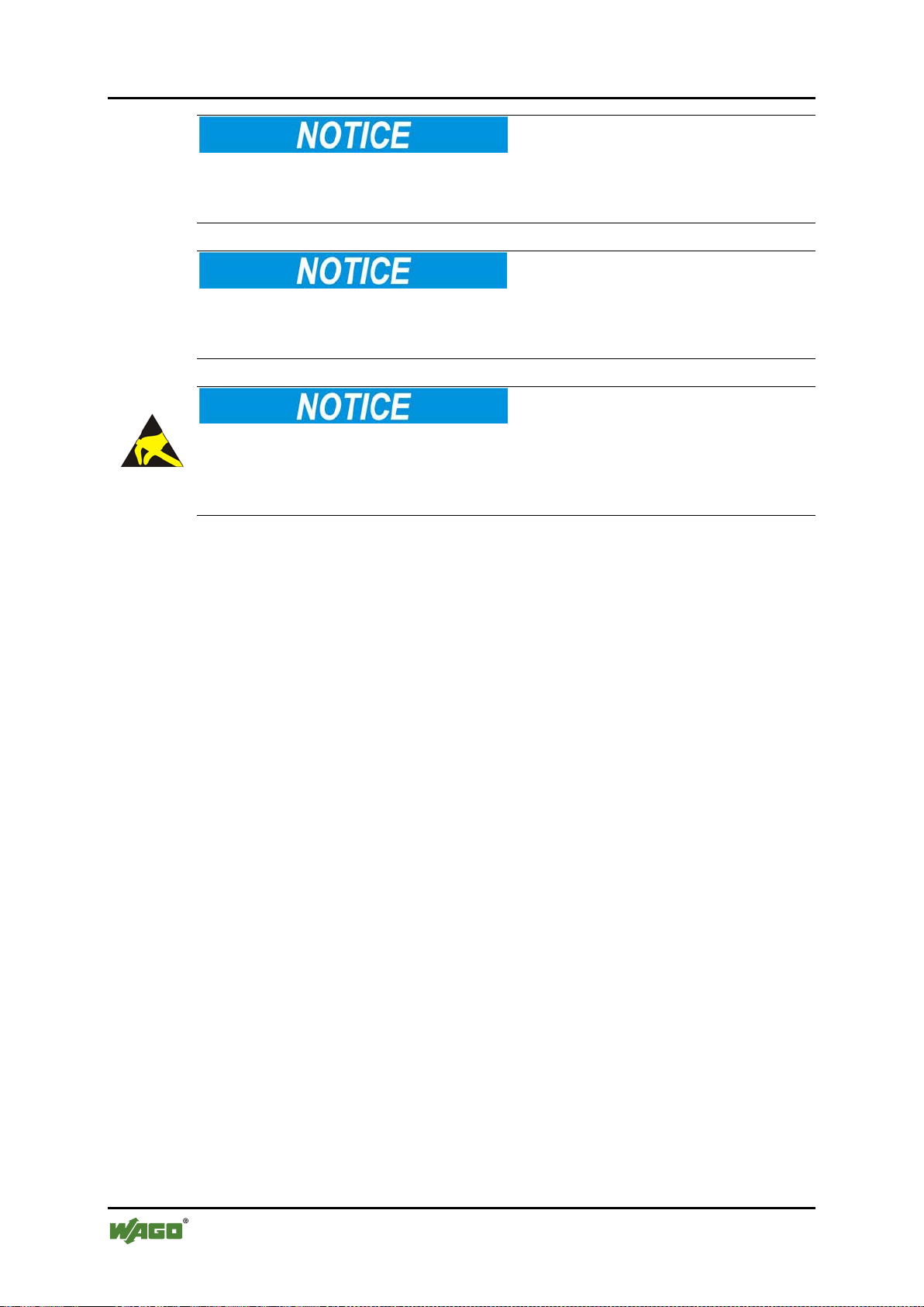
Pos: 13.4.6 /All e Serien (All g emeine Mod ul e) / Wichtige Er lä uterunge n/ Sicherheit s- und sonstige Hinwei se/Achtung/Achtung: _Warnung vor Sachschäden durch elektr ostatische Aufladung_ - Erläuterung @ 13\mod_1343310227702_21.docx @ 101044 @ @ 1
Damage to Property Caused by Electrostatic Discharge (ESD)!
Indicates a potentially hazardous situation which, if not avoided, may result in
damage to property.
Pos: 13.4.7 /All e Serien (All g emeine Mod ul e) / Wichtige Er lä uterunge n/ Sicherheit s- und sonstige Hinweise/Hinweis/Hinweis: _Wichtiger Hinweis allgemein_ - Eräuterung @ 13\mod_1343310326906_21.docx @ 101047 @ @ 1
Important Note!
Indicates a potential malfunction which, if not avoided, however, will not result in
damage to property.
Pos: 13.4.8 /All e Serien (All g emeine Mod ul e) / Wichtige Er lä uterunge n/ Sicherheit s- und sons tige Hinwei se/Infor mation/Inf ormation: _Weitere I nformatio n allgemei n_ - Erläu ter ung @ 13\mod_1343310439814_21.do cx @ 101051 @ @ 1
Manual
Version 1.1.0
Page 7

WAGO-I/O-SYSTEM 750 Notes about this Documentation 7
750-402 4DI 24V DC 3.0ms
Additional Information:
Refers to additional information which is not an integral part of this
documentation (e.g., the Internet).
Pos: 13.5 /Dokumentation allgemein/Glieder ungselemente/---Seitenwechs el--- @ 3\mod_1221108045078_0 .docx @ 21810 @ @ 1
Manual
Version 1.1.0
Page 8
8 Notes about this Documentation WAGO-I/O-SYSTEM 750
Table 2: Number notation
Number code
Example
Note
Decimal
100
Normal notation
Hexadecimal
0x64
C notation
Binary
'100'
'0110.0100'
In quotation marks, nibble separated with
dots (.)
Table 3: Font conventions
Font type
Indicates
italic
Names of paths and data files are marked in italic-type.
e.g.: C:\Programme\WAGO-I/O-CHECK
Menu
Menu items are marked in bold letters.
e.g.: Save
>
A greater-than sign between two names means the selection of a
e.g.: File > New
Input
Designation of input or optional fields are marked in bold letters,
e.g.: Start of measurement range
“Value”
Input or selective values are marked in inverted commas.
e.g.: Enter the value “4 mA” under Start of measurement range.
[Button]
Pushbuttons in dialog boxes are marked with bold letters in square
e.g.: [Input]
[Key]
Keys are marked with bold letters in square brackets.
e.g.: [F5]
750-402 4DI 24V DC 3.0ms
Pos: 13.6 /Al le Seri en (Allgemei ne Modul e)/Hinweis e z ur D o k u me nt ation/Zahl e nsysteme @ 3\ mod_1221059454015_21.docx @ 21711 @ 2 @ 1
1.4 Number Notation
Pos: 13.7 /All e Ser i en (Allgemei ne Module)/ H i nweise zur D o ku mentation /Sc hriftko n vent i onen @ 3\mod_1221059521437_21.docx @ 21714 @ 2 @ 1
1.5 Font Conventions
menu item from a menu.
brackets.
Pos: 14 /Dokum e nt ation allge mei n/Glieder ungselem e nte/---Seiten wechsel--- @ 3\mod_1221108045078_0.docx @ 218 10 @ @ 1
Manual
Version 1.1.0
Page 9

WAGO-I/O-SYSTEM 750 Important Notes 9
750-402 4DI 24V DC 3.0ms
Pos: 15 /All e Serien ( Allgemei ne Module)/Ü berschri ften für al le Serien/Wichtige Erläuterungen/Wichtige Erläuterungen - Überschrift 1 @ 4\mod_1241428899156_21.docx @ 32170 @ 1 @ 1
2 Important Notes
Pos: 16.1 /Al le Seri en (Allgemei ne Dokum ente) (All gemeine Mo dule)/Wic htige Erlä uterunge n/Einleit ung Wichtig e Erläuter ungen @ 3\ mod_1221059818031_21.docx @ 21717 @ @ 1
This section includes an overall summary of the most important safety
requirements and notes that are mentioned in each individual section. To protect
your health and prevent damage to devices as well, it is imperative to read and
carefully follow the safety guidelines.
Pos: 16.2 /Al le Seri en (Allgemei ne Modul e)/Überschr iften für alle Seri en/Wichti ge Erläuter ungenRec htliche Gr undlagen - Überschri ft 2 @ 3\ mod_1221060626343_21.docx @ 21726 @ 2 @ 1
2.1 Legal Bases
Pos: 16.3 /Alle Se r ie n ( Allgemeine Dokumente) (Allgemeine Module)/Wichtige Erläuterungen/Änderungsvorbehalt - Überschri ft 3 und I nhalt @ 3\mod_1221060036484_21.docx @ 21720 @ 3 @ 1
2.1.1 Subject to Changes
WAGO Kontakttechnik GmbH & Co. KG reserves the right to provide for any
alterations or modifications that serve to increase the efficiency of technical
progress. WAGO Kontakttechnik GmbH & Co. KG owns all rights arising from
the granting of patents or from the legal protection of utility patents. Third-party
products are always mentioned without any reference to patent rights. Thus, the
existence of such rights cannot be excluded.
Pos: 16.4 /Serie 750 (WAGO-I/O-S YSTEM)/ Wic htige Erlä ut er u ngen/Pers onalquali fi kation 750- xxxx @ 3\mod_1224061208046_21.docx @ 24063 @ 3 @ 1
2.1.2 Personnel Qualifications
All sequences implemented on Series 750 devices may only be carried out by
electrical specialists with sufficient knowledge in automation. The specialists
must be familiar with the current norms and guidelines for the devices and
automated environments.
All changes to the coupler or controller should always be carried out by qualified
personnel with sufficient skills in PLC programming.
Pos: 16.5 /Serie 750 (WAGO-I/O-S YSTEM)/ Wic htige Erlä ut er u ngen/Bes ti m m u ng s g e mäß e Verwend ung 7 50- xxxx @ 3\mod_1224064151234_21.docx @ 24070 @ 3 @ 1
2.1.3 Use of the 750 Series in Complianc e wit h Unde rlying Provisions
Couplers, controllers and I/O modules found in the modular WAGO-I/OSYSTEM 750 receive digital and analog signals from sensors and transmit them
to the actuators or higher-level control systems. Using programmable controllers,
the signals can also be (pre-) processed.
The components have been developed for use in an environment that meets the
IP20 protection class criteria. Protection against finger injury and solid impurities
up to 12.5 mm diameter is assured; protection against water damage is not
ensured. Unless otherwise specified, operation of the components in wet and
dusty environments is prohibited.
Operating 750 Series components in home applications without further measures
is only permitted if they meet the emission limits (emissions of interference)
according to EN 61000-6-3. You will find the relevant information in the section
on "WAGO-I/O-SYSTEM 750" "System Description" "Technical Data" in
the manual for the used fieldbus coupler/controller.
Manual
Version 1.1.0
Page 10

10 Important Notes WAGO-I/O-SYSTEM 750
750-402 4DI 24V DC 3.0ms
Appropriate housing (per 94/9/EG) is required when operating the WAGO-I/OSYSTEM 750 in hazardous environments. Please note that a prototype test
certificate must be obtained that confirms the correct installation of the system in
a housing or switch cabinet.
Pos: 16.6 /Al le Seri en (Allgemei ne Dokum ente) (All gemeine Mo dule)/Wic htige Erlä uterunge n/Technis cher Zustan d der Ger äte - Übersc hrift 3 und Inh alt @ 3\mod_1221060446109_21.doc x @ 21723 @ 3 @ 1
2.1.4 Technical Condition of Spec ified Devices
The components to be supplied Ex Works, are equipped with hardware and
software configurations, which meet the individual application requirements.
WAGO Kontakttechnik GmbH & Co. KG will be exempted from any liability in
case of changes in hardware or software as well as to non-compliant usage of
components.
Please send your request for modified and new hardware or software
configurations directly to WAGO Kontakttechnik GmbH & Co. KG.
Pos: 16.7 /Dokumentation allgemein/Glieder ungselemente/---Seitenwechs el--- @ 3\mod_1221108045078_0 .docx @ 21810 @ @ 1
Manual
Version 1.1.0
Page 11
WAGO-I/O-SYSTEM 750 Important Notes 11
750-402 4DI 24V DC 3.0ms
Pos: 16.8 /All e Ser i en (Allgemei ne Module)/ Ü berschrift en für alle Ser i e n/Wichtig e Er l ä ut er ungenSic her heitshi n weis e - Überschr i ft 2 @ 6\ mod_12601802999 87_21.docx @ 46724 @ 2 @ 1
2.2 Safety Advice (Precautions)
Pos: 16.9 /Al le Seri en (Allgemei ne Dokum ente) (All gemeine Mo dule)/Wic htige Erlä uterunge n/Sicherhei tshinweis e/Einleit ung Sicher heitshin weise Hard ware @ 6\mod_1260180170493_21.docx @ 46720 @ @ 1
For installing and operating purposes of the relevant device to your system the
following safety precautions shall be observed:
Pos: 16.10. 1 /Alle Ser ien (Allge meine Do kumente) (A llgemein e Module)/ Wichtige Erläuteru ngen/Sich erheitshin weise/Gef ahr/Gefahr : Nicht an Geräten unter Spann ung arbeit en! @ 6\mod_1260180365327_21.docx @ 46727 @ @ 1
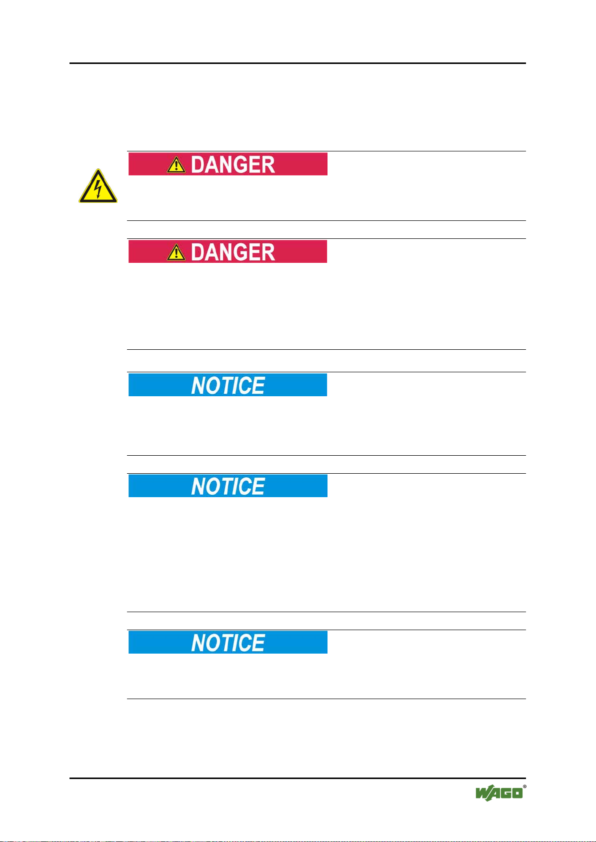
Do not work on components while energized!
All power sources to the device shall be switched off prior to performing any
installation, repair or maintenance work.
Pos: 16.10. 2 /Serie 75 0 (WAGO-I/O- SYSTEM) /Wichtige Er läuterung en/Sicher heits- un d sonstige H inweise /Gefahr/Ge fahr: Einb au 0750-xx x x nur i n Ge häusen, Sc hr ä nken oder el e ktr is c hen Betrie bsr ä umen! @ 6\mod_1260180556692_21.docx @ 46731 @ @ 1
Installation only in appropriate housings, cabinets or in electrical operation
rooms!
The WAGO-I/O-SYSTEM 750 and its components are an open system. As such,
install the system and its components exclusively in appropriate housings,
cabinets or in electrical operation rooms. Allow access to such equipment and
fixtures to authorized, qualified staff only by means of specific keys or tools.
Pos: 16.10. 3 /Alle Ser ien (Allge meine Do kumente) (A llgemein e Module)/ Wichtige Erläuteru ngen/Sich erheitshin weise/Gef ahr/Gefahr : Unfall verhütungs vorschrift en beachte n! @ 6\mod_1260180657000_21.docx @ 46735 @ @ 1
Pos: 16.10.4 / Alle Seri en (Allgem eine Doku mente) (All gemeine M odule)/ Wichtige Er läuterung en/Sicher heitshinw eise/Gefahr /Gefahr: Auf normg erechten A nschluss achten! @ 6\mod_1260180753479_21.docx @ 46739 @ @ 1
Pos: 16.11.1 /Al le Serien (Allgemei ne D okumente) (Allgemei n e M o dule)/Wich tige Erläut er ungen/Sic herheits hi n w ei s e /Ac htung/Ac ht ung: Defek t e od er beschädigt e Geräte aus ta us c hen! @ 6\mod_1260180857358_21.docx @ 46743 @ @ 1
Replace defective or damaged devices!
Replace defective or damaged device/module (e.g., in the event of deformed
contacts), since the long-term functionality of device/module involved can no
longer be ensured.
Pos: 16.11. 2 /Alle Ser ien (Allge meine Do kumente) (A llgemein e Module)/ Wichtige Erläuteru ng en /Sicherh ei ts hinweise /Ac htung/Ac ht ung: Gerät e vor kr i ec he nden und isol i er enden Stof f en s ch ützen! @ 6\mod_1260181036216_21.docx @ 46747 @ @ 1
Protect the components against materials having seeping and insulating
properties!
The components are not resistant to materials having seeping and insulating
properties such as: aerosols, silicones and triglycerides (found in some hand
creams). If you cannot exclude that such materials will appear in the component
environment, then install the components in an enclosure being resistant to the
above-mentioned materials. Clean tools and materials are imperative for handling
devices/modules.
Pos: 16.11. 3 /Alle Ser ien (Allge meine Do kumente) (A llgemein e Module)/ Wichtige Erläuteru ngen/Sich erheitshin weise/Acht ung/Acht ung: Reinig ung nur mit zulässig en Mater ialien! @ 6\mod_1260181203293_21.docx @ 46751 @ @ 1
Cleaning only with permitted materials!
Clean soiled contacts using oil-free compressed air or with ethyl alcohol and
leather cloths.
Pos: 16.11. 4 /Alle Ser ien (Allge meine Do kumente) (A llgemein e Module)/ Wichtige Erläuteru ngen/Sich erheitshin weise/Acht ung/Acht ung: Kein K ontaktspr ay verwe nden! @ 6\mod_1260181290808_21.docx @ 46755 @ @ 1
Manual
Version 1.1.0
Page 12
12 Important Notes WAGO-I/O-SYSTEM 750
750-402 4DI 24V DC 3.0ms
Do not use any contact spray!
Do not use any contact spray. The spray may impair contact area functionality in
connection with contamination.
Pos: 16.11. 5 /Alle Ser ien (Allge meine Do kumente) (A llgemein e Module)/ Wichtige Erläuteru ngen/Sich erheitshin weise/Acht ung/Acht ung: Verpol ung ver meiden! @ 6\ mod_1260184045744_21.docx @ 46767 @ @ 1
Do not reverse the polarity of connection lines!
Avoid reverse polarity of data and power supply lines, as this may damage the
devices involved.
Pos: 16.11. 6 /Alle Ser ien (Allge meine Do kumente) (A llgemein e Module)/ Wichtige Erläuteru ngen/Sich erheitshin weise/Acht ung/Acht ung: Elektr ost atische Entl adung verm ei d en! @ 6\mod_1260181364729_21.docx @ 46759 @ @ 1
Avoid electrostatic discharge!
The devices are equipped with electronic components that you may destroy by
electrostatic discharge when you touch. Pay attention while handling the devices
to good grounding of the environment (persons, job and packing).
Pos: 17 /Dokum e nt ation allge mein/Glie derungsele mente/---Seit enwechsel--- @ 3\ mod_1221108045078_0.docx @ 21810 @ @ 1
Manual
Version 1.1.0
Page 13
WAGO-I/O-SYSTEM 750 Device Description 13
750-402 4DI 24V DC 3.0ms
Pos: 18 /All e Serien ( Allgemei ne Module)/Ü berschri ften für al le Serie n/Geräteb eschreibung /Gerätebe schreibu ng - Übersc hr i ft 1 @ 3\ mod_1233756084656_21.docx @ 27096 @ 1 @ 1
3 Device Description
Pos: 19.1 /Serie 750 (WAGO-I/O-S YSTEM)/ Ger ätebeschr ei bung/Einl ei tung/An w en d ung/DI/An w en dung 750-x4 xx DI @ 3\mod_1233762736718_21.docx @ 27108 @ @ 1
The digital input module 750-402 receives control signals from digital field (e.g.
of sensors, transmitters, switches or proximity switches).
Pos: 19.2 /Serie 750 (WAGO-I/O-S YSTEM)/ Gerätebesc hreibung/Ei nleitung /I/O-Besc hreibung/DI /I/O-Besc hreibung 7 50-04xx 4 DI 2-/3-Leiter (DI, 24 V und 0 V) @ 6\mod_1263895132463_21.docx @ 48086 @ @ 1
The I/O module has 4 input channels, providing a direct connection to two 2- or 3wire sensors. Two additional sensors may be connected via potential distributor.
The input signals are connected to the following CAGE CLAMP® terminals: DI 1
Pos: 19.3 /Dokumentation allgemein/Glieder ungselemente/------Leerzeile------ @ 3\mod_1224662755687_0.do cx @ 24460 @ @ 1
Pos: 19.4 /Serie 750 (WAGO-I/O-S YSTEM)/ Wic htige Erlä ut er u ngen/Sich er h eits- und s onstige Hi nweise/Hi nweis/Hin weis: DI P otential vervielfält igungsmod ule für Se nsorvers orgung eins etzen @ 3\ mod_1233762069125_21.docx @ 27105 @ @ 1
... DI 4, 24 V and 0 V.
Use field side connection modules!
Where required, use the appropriate field side connection modules for power
supply to the sensors.
Pos: 19.5 /Serie 750 (WAGO-I/O-S YSTEM)/ Gerätebesc hreibung/Ei nleitung /I/O-Besc hreibung/ Allgemein/V erweis auf Kapitel "Anschlüss e" @ 8\mod_1276775378035_21.docx @ 57956 @ @ 1
Pos: 19.6 /Serie 750 (WAGO-I/O-S YSTEM)/ Gerätebesc hreibung/Ei nleitung /I/O-Besc hreibung/ Allgemein/V erweis auf Kapitel "Geräte a nschließen" > "Ansc hlussbeis piel(e)" @ 5\mod_1246015203281_21.docx @ 36298 @ @ 1
The assignment of the connections is described in the "Connections" section.
Connection examples are shown in section "Connecting Devices" > "Connection
Example(s)".
Pos: 19.7 /Serie 750 (WAGO-I/O-S YSTEM)/ Gerätebesc hreibung/Ei nleitung /I/O-Besc hreibung/DI /I/O-Besc hreibung 7 50-x4xx DI RC-Fil t er 3, 0 ms @ 3\mod_1233755071062_21.docx @ 27080 @ @ 1
Each input channel has an RC noise rejection filter with a time constant of 3.0 ms.
Pos: 19.8 /Serie 750 (WAGO-I/O-S YSTEM)/ Gerätebesc hreibung/Ei nleitung /I/O-Besc hreibung/DI /I/O-Besc hreibung 7 50-x4xx DI HSS / posi tivschalt end (24 V) @ 3\mod_1233831724648_21.docx @ 27231 @ @ 1
The I/O module inputs provide high-side switching. If the 24V potential for field
power is switched to an input connection, the signal status for the corresponding
input channel is set to "high."
Pos: 19.9 /Serie 750 (WAGO-I/O-S YSTEM)/ Gerätebesc hreibung/Ei nleitung /LED-Anzei ge/LED Zu stand Sig nal @ 3\mod_1233755258578_21.docx @ 27087 @ @ 1
Pos: 19.10 / Serie 750 ( WAGO-I/O-S YSTEM)/G erätebeschr eibung/Ei nleitung/ LED-Anzeig e/Verweis auf Kapi tel "Anzeig eel emente" @ 5\ mod_1246010525000_21.docx @ 36194 @ @ 1
A green LED indicates the switched status of each channel.
The meaning of the LEDs is described in the “Display Elements” section.
Pos: 19.11 / Serie 750 ( WAGO-I/O-S YSTEM)/G erätebeschr eibung/Ei nleitung/ Versorgu ng/Versor gung 24 V, 0 V über L eistungs kontakte Stan d ar d @ 3\ mod_1226498974531_21.docx @ 25020 @ @ 1
The I/O module receives the 24 V voltage supply for the field level from an
upstream I/O module or from the fieldbus coupler/controller via the power
contacts used as blade contacts. It then provides this potential to subsequent I/O
modules via the power contacts used as spring contacts.
Pos: 19.12 / Serie 750 ( WAGO-I/O-S YSTEM)/ Wichtige Erl äuterung en/Sicher heits- und s onstige Hi nweise/Ac htung/Ac htung: Maxi maler Str om Leistu ngskontak te 10 A @ 3 \mod_1226499143500_21.docx @ 25029 @ @ 1
Do not exceed maximum current via power contacts!
The maximum current to flow through the power contacts is 10 A.
Greater currents can damage the power contacts.
When configuring the system, ensure that this current is not exceeded. If
exceeded, an additional potential feed module must be used.
Pos: 19.13 / Serie 750 ( WAGO-I/O-S YSTEM)/ Wichtige Erl äuterung en/Sicher heits- und s onstige Hi nweise/Hi nweis/Hi nweis: Pote ntialeins peiseklem me für Erd e einsetze n! @ 3\mod_1226499037468_21.docx @ 25023 @ @ 1
Use potential feed module for Ground (earth)!
The I/O module has no power contacts for PE intake and transfer. Use a potential
feed module when a PE feed is needed for the subsequent I/O modules.
Pos: 19.14 /Ser i e 7 50 ( WAGO-I/O-SYS TEM)/Gerät ebeschr eibung/Ei nleitung/V ersorgung /Galvanisc he Trennu ng Feld/S ystem @ 3\mod_1233756478750_21.docx @ 27102 @ @ 1
Manual
Version 1.1.0
Page 14

14 Device Description WAGO-I/O-SYSTEM 750
750-402 4DI 24V DC 3.0ms
The field voltage and the system voltage are electr ical l y isolated from each other.
Pos: 19.15 /Ser i e 7 50 ( WAGO-I/O-SYS T EM)/Gerät e be schreibu ng /Einleitung /Versorg u ng/Anord nu ng unt er Berücksi c htigung der L ei st ungskonta k t e bel i e big @ 3\mod_1233756233468_21.doc x @ 27099 @ @ 1
With consideration of the power jumper contacts, the individual modules can be
arranged in any combination when configuring the fieldbus node. An arrangement
in groups within the group of potentials is not necessary.
Pos: 19.16 / Serie 750 ( WAGO-I/O-S Y ST EM)/Gerät ebeschrei b ung/Einlei t ung/Einsa tzbereich/ Einsatzb er ei c h 750-xxxx al l e K op pl er / C ontroller ohne Eins chränkung @ 3\mod_1232541691906_21.docx @ 26522 @ @ 1
The I/O module 750-402 can be used with all fieldbus couplers/controllers of the
WAGO-I/O-SYSTEM 750.
Pos: 20 /Dokum e nt ation allge mei n/Glieder ungselem e nte/---Seitenwechsel--- @ 3\mod_1221108 045078_0.docx @ 21810 @ @ 1
Manual
Version 1.1.0
Page 15
WAGO-I/O-SYSTEM 750 Device Description 15
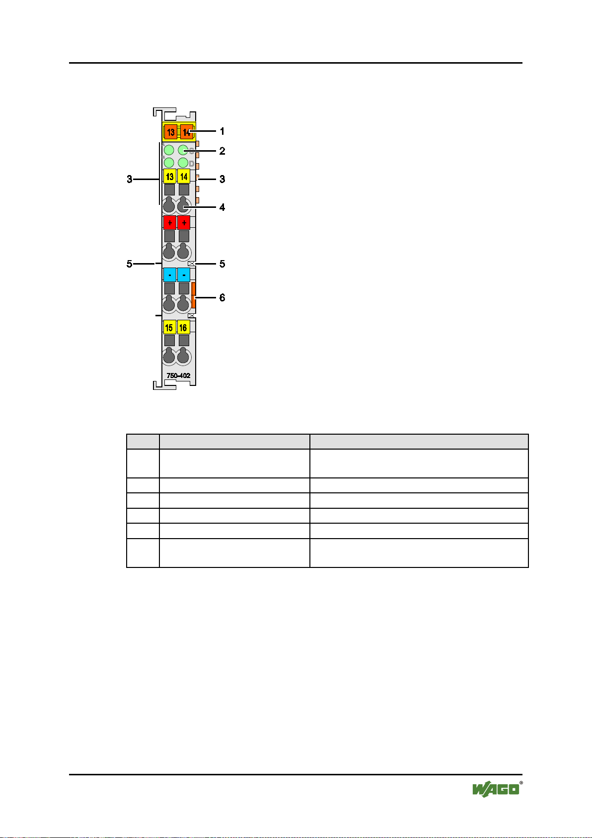
Table 1: Caption acc. to figure “View”
Pos.
Description
Details see section
1
Marking possibility with
Mini-WSB
--2
Status-LEDs
“Device Description” > “Display Elements”
3
Data contacts
“Device Description” > ”Connectors”
4
CAGE CLAMP® supplies
“Device Description” > ”Connectors”
5
Power jumper contacts
“Device Description” > ”Connectors”
6
Release tab
“Mounting” > ”Inserting and Removing
Devices”
750-402 4DI 24V DC 3.0ms
Pos: 21 /All e Serien ( Allgemei ne Module)/Ü berschri ften für al le Serie n/Geräteb eschreibung /Ansicht - Ü berschrif t 2 @ 4\mod_1240984217343_21.docx @ 31958 @ 2 @ 1
3.1 View
Pos: 22 /Ser ie 750 ( WAGO-I/O-SYST EM )/Gerät eb es c hreibung/ A ns i c ht /Digitalei ngangs kle m m en /Ansicht 7 50- 0402 @ 9\ mod_1295861125135_21.docx @ 68661 @ @ 1
Figure 1: View
Pos: 23 /Ser ie 750 ( WAGO-I/O-SYST EM )/Gerät eb es c hreibung/ A ns i c ht /Ansicht C ag eC l amp®_Leg ende mit LED @ 1 5\ mod_1370867188922_21.docx @ 122225 @ @ 1
Pos: 24 /Dokum e nt ation allge mei n/Glieder ungselem e nte/---Seiten wechsel--- @ 3\mod_1221108045078_0.docx @ 218 10 @ @ 1
Manual
Version 1.1.0
Page 16

16 Device Description WAGO-I/O-SYSTEM 750
750-402 4DI 24V DC 3.0ms
Pos: 25 /All e Serien ( Allgemei ne Module)/Ü berschri ften für al l e S erien/Gerä tebeschr ei b u ng /Anschlü ss e - Üb er s c hrift 2 @ 4\mod_1240984262656_21.docx @ 31961 @ 22 @ 1
3.2 Connectors
Pos: 26 /Ser ie 750 ( WAGO-I/O-SYST EM)/Gerät ebeschrei bung/Ansc hlüsse/Da tenkontak te/Klemme nbus - Übers c hrift 3 @ 6\mod_1256294684083_21.docx @ 4 3660 @ 3 @ 1
3.2.1 Data Contacts/Interna l Bus
Pos: 27.1 /Serie 750 (WAGO-I/O-S YSTEM)/ Gerätebesc hreibung/A nschlüsse /Datenkon takte - Fel dbuskoppl er/-controll er, Abbil dung und B eschreibu ng @ 3\mod_1231771259187_21.docx @ 26002 @ @ 1
Communication between the coupler/controller and the I/O modules as well as the
system supply of the I/O modules is carried out via the internal bus. It is
comprised of 6 data contacts, which are available as self-cleaning gold spring
contacts.
Figure 2: Data contacts
Pos: 27.2 /Serie 750 (WAGO-I/O-SYSTEM)/Wichti g e Erläuteru ngen/Sich er h eits- und s onstige Hi nweise/Ac htung/Ach tung: Bus klemmen ni cht auf G oldfederk ontakte leg en! @ 7\mod_1266318463636_21.docx @ 50695 @ @ 1
Do not place the I/O modules on the gold spring contacts!
Do not place the I/O modules on the gold spring contacts in order to avoid soiling
or scratching!
Pos: 27.3 /Serie 750 (WAGO-I/ O-SYSTEM)/ Wi c htige Erläut erungen/ Si c h er h ei t s- und sonstige Hinwei se/Achtung/Achtung: ESD - Auf gute Erd ung der U mgebung ac hten! @ 7\ mod_1266318538667_21.docx @ 50708 @ @ 1
Ensure that the environment is well grounded!
The modules are equipped with electronic components that may be destroyed by
electrostatic discharge. When handling the modules, ensure that the environment
(persons, workplace and packing) is well grounded. Avoid touching conductive
components, e.g. data contacts.
Pos: 28 /D okumentatio n allgemei n/Glieder ungselem ente/---Seite nwechsel--- @ 3\mod_1221108045078_0.docx @ 21810 @ @ 1
Manual
Version 1.1.0
Page 17

WAGO-I/O-SYSTEM 750 Device Description 17
Table 4: Caption acc. to view “Power jumper contacts”
Contact
Type
Function
1
Spring contact
Potential transmission (Uv) for field supply
2
Spring contact
Potential transmission (0 V) for field supply
3
Blade contact
Potential feed-in (0 V) for field supply
4
Blade contact
Potential feed-in (Uv) for field supply
750-402 4DI 24V DC 3.0ms
Pos: 29 /Ser ie 750 ( WAGO-I/O-SYST EM)/Gerät ebeschrei bung/Ansc hlüsse/Lei stungs kontakte/Fel dversorg ung - Übersc hrift 3 @ 6\mod_1256294692864_21.docx @ 43664 @ 3 @ 1
3.2.2 Power Jumper Contacts/Field Supply
Pos: 30.1 /Serie 750 (WAGO-I/O-S YSTEM)/ Wic htige Erlä ut er u ngen/Sich er h eits- und s onstige Hi nweise/Vor sicht/V orsicht: Ver letzungsg efahr durc h scharf kantige M esserkonta kte! @ 6\mod_1256193279401_21.docx @ 43414 @ @ 1
Risk of injury due to sharp-edged male contacts!
The male contacts are sharp-edged. Handle the module carefully to prevent injury.
Pos: 30.2 /Serie 750 (WAGO-I/O-S YSTEM)/ Gerätebesc hreibung/A nschlüsse /Leistung skontakte 2 LK (Mess er/Leistu ngskonta kte 2 LK (Me sser/Fed er) - Einleit ung @ 15\mod_1371721641099_21.docx @ 123714 @ @ 1
The I/O module 750-402 has 2 self-cleaning power jumper contacts that supply
and transmit power for the field side. The contacts on the left side of the I/O
module are designed as male contacts and the contacts on the right side as spring
contacts.
Pos: 30.3 /Serie 750 (WAGO-I/O-S YSTEM)/G erätebesc hreibung/A nschlüsse /Leistung skontakte 2 LK (Mess er/Leistu ngskontak te 2 LK (Me sser/Fed er) - Abbil du ng (ei nfache Brei te) @ 15\mod_1367500700037_21.docx @ 118396 @ @ 1
Figure 3: Power jumper contacts
Pos: 30.4 /S erie 750 (WAGO-I/O-SYSTEM )/Geräte beschreibu ng/Anschl üsse/Leist ungskont akte 2 LK ( Messer/Lei stungsk ontakte 2 L K (Messer /Feder) - L eg e nd e @ 15\mod_1371721352500_21.docx @ 123710 @ @ 1
Pos: 30.5 /Serie 750 (WAGO-I/O-S YSTEM)/ Wic htige Erlä ut er u ngen/Sich er h eits- und so nst i g e Hinweise/ Achtung/A c h tu ng: Maximal er Strom Leis t ung skontakt e 10 A @ 3\mod_1226499143500_21.docx @ 25029 @ @ 1
Do not exceed maximum current via power contacts!
The maximum current to flow through the power contacts is 10 A.
Greater currents can damage the power contacts.
When configuring the system, ensure that this current is not exceeded. If
exceeded, an additional potential feed module must be used.
Pos: 30.6 /Serie 750 (WAGO-I/O-S YSTEM)/ Wic htige Erlä ut er u ngen/Sich er h eits- und so nst i g e Hinweise/ Hi n weis/Hin w ei s : Po t e nti aleinspei s eklemme für Er d e ei nsetzen! @ 3\mod_1226499037468_21.docx @ 25023 @ @ 1
Use potential feed module for Ground (earth)!
The I/O module has no power contacts for PE intake and transfer. Use a potential
feed module when a PE feed is needed for the subsequent I/O modules.
Pos: 31 /Dokum e nt ation allge mei n/Glieder ungselem e nte/---Seiten wechsel--- @ 3\mod_1221108045078_0.docx @ 218 10 @ @ 1
Manual
Version 1.1.0
Page 18

18 Device Description WAGO-I/O-SYSTEM 750
Table 5: Caption acc. to figure “CAGE CLAMP® Connectors”
Channel
Designation
Connector
Function
1
DI 1
1
Input DI 1: Signal voltage
2
DI 2
5
Input DI 2: Signal voltage
3
DI 3
4
Input DI 3: Signal voltage
4
DI 4
8
Input DI 4: Signal voltage
-
+24 V
2
Sensor supply +24 V
-
+24 V
6
Sensor supply +24 V
-
0 V
3
Sensor supply 0 V
-
0 V
7
Sensor supply 0 V
750-402 4DI 24V DC 3.0ms
Pos: 32 /Ser ie 750 ( WAGO-I/O-SYST EM)/Gerät ebeschrei bung/Ansc hlüsse/CA GE CLAMP- Anschlüss e - Überschri ft 3 @ 6\ mod_1256296337770_21.docx @ 43674 @ 3 @ 1
3.2.3 CAGE CLAMP® Connectors
Pos: 33 /Ser ie 750 ( WAGO-I/O-SYST EM)/Geräteb eschreibu ng /Anschl üss e/Digital eingangs kle m m e n/Anschl üss e 750-04xx 4 DI 3-Leiter (DIn, 24 V, 0 V) @ 9\mod_129586 1237712_21.docx @ 68665 @ @ 1
Figure 4: CAGE CLAMP
®
Connectors
Pos: 34 /Ser ie 750 ( WAGO-I/O-SYST EM )/Wichti g e Er l ä ut erungen/ Si c h er h ei ts - und sonstige Hi nweise/Hi nweis/Hin weis: DI P otential vervielfälti gungsmod ule für Se nsorversor gung einse tzen @ 3\ mod_1233762069125_21.docx @ 27105 @ @ 1
Use field side connection modules!
Where required, use the appropriate field side connection modules for power
supply to the sensors.
Pos: 35 /Dokum e nt ation allge mei n/Glieder ungselem e nte/---Seiten wechsel--- @ 3\mod_1221108045078_0.docx @ 218 10 @ @ 1
Manual
Version 1.1.0
Page 19

WAGO-I/O-SYSTEM 750 Device Description 19
Table 6: Caption acc. to figure “Display elements”
Channel
Designation
LED
State
Function
out
Input DI 1: Signal voltage „0“
green
Input DI 1: Signal voltage „1“
out
Input DI 2: Signal voltage „0“
green
Input DI 2: Signal voltage „1“
out
Input DI 3: Signal voltage „0“
green
Input DI 3: Signal voltage „1“
out
Input DI 4: Signal voltage „0“
green
Input DI 4: Signal voltage „1“
750-402 4DI 24V DC 3.0ms
Pos: 36 /All e Serien ( Allgemei ne Module)/Ü berschri ften für al le Serie n/Geräteb eschreibung /Anzeigeel emente - Überschri ft 2 @ 4\mod_1240984390875_21.docx @ 31964 @ 22 @ 1
3.3 Display Elements
Pos: 37 /Ser ie 750 ( WAGO-I/O-SYST EM )/Gerät eb es c hreibung/ A nz eigeelem en te/Digital ei ngangs kle m m en /Anzeigeel emente 750- 04xx 4 DI (Agn, Bg n, Cgn, Dg n) @ 9\mod_1291641003036_21.do cx @ 67080 @ @ 1
Figure 5: Display elements
1 Status DI 1 A
2 Status DI 2 C
3 Status DI 3 B
4 Status DI 4 D
Pos: 38 /Dokum e nt ation allge mei n/Glieder ungselem e nte/---Seiten wechsel--- @ 3\mod_1221108045078_0.docx @ 218 10 @ @ 1
Manual
Version 1.1.0
Page 20

20 Device Description WAGO-I/O-SYSTEM 750
750-402 4DI 24V DC 3.0ms
Pos: 39 /All e Serien ( Allgemei ne Module)/Ü berschri ften für al le Serie n/Geräteb eschreibung /Schemat isches Sc haltbild - Ü berschrift 2 @ 4\mod_1240984441312_21.docx @ 31967 @ 2 @ 1
3.4 Schematic Diagram
Pos: 40 /Ser ie 750 ( WAGO-I/O-SYST EM)/Gerät ebeschrei bung/Sch ematische Schaltbil der/Digit aleingangs klemmen/Sc hematisc hes Schal tbild 750-0 40 2 @ 9\mod_1295863706202_21.docx @ 68711 @ @ 1
Figure 6: Schematic d iagram
Pos: 41 /Dokum e nt ation allge mei n/Glieder ungselem e nte/---Seiten wechsel--- @ 3\mod_1221108045078_0.docx @ 21810 @ @ 1
Manual
Version 1.1.0
Page 21

WAGO-I/O-SYSTEM 750 Device Description 21
Table 7: Technical data – device
Width
12 mm
Height (from upper edge of 35 DIN rail)
64 mm
Depth
100 mm
Weight
48,5 g
Table 2: Technical data – supply
Voltage supply
Via system voltage terminal bus
(5 V DC) and power contacts (24 V DC)
Current consumption
. (internal).
(5 V DC)
7.5 mA
Input current
. (Field).
(24 V DC)
Total input current + sensor supply
Voltage via power jumper contacts
24 VDC (-25 % … + 30 %)
Current via power jumper contacts
10 A
Isolation (Peak value)
500 V System/Field
Table 3: Technical data – communication
Internal bit width (Terminal bus)
4 bit in
Table 4: Technical data – inputs
No. of inputs
4
Signal voltage
- 3 V … + 30 V DC
Signal voltage (0)
- 3 V … + 5 V DC
Signal voltage (1)
+ 15 V … + 30 V DC
Input filter
3.0 ms
Input current
typ
.
4.5 mA
750-402 4DI 24V DC 3.0ms
Pos: 42 /All e Serien ( Allgemei ne Module)/Ü berschri ften für al le Serie n/Geräteb eschreibung /Technisc he Daten - Ü berschrif t 2 @ 3\mod_1232967587687_21.docx @ 26924 @ 2 @ 1
3.5 Technical Data
Pos: 43 /Ser ie 750 ( WAGO-I/O-SYST EM)/Ger ätebeschrei bung/Tec hnische Da ten/Digit aleingang sklemmen /Technisch e Daten 75 0-0402 @ 9\mod_1295863611535_21.docx @ 68707 @ 3333 @ 1
3.5.1 Device data
3.5.2 Supply
typ
typ
3.5.3 Communication
3.5.4 Inputs
Pos: 44 /Dokum e nt ation allge mei n/Glieder ungselem e nte/---Seiten wechsel--- @ 3\mod_1221108045078_0.docx @ 218 10 @ @ 1
Manual
Version 1.1.0
Page 22

22 Device Description WAGO-I/O-SYSTEM 750
Table 8: Technical Data – Field Wiring
Wire connection
CAGE CLAMP®
Cross section
0.08 mm² … 2.5 mm², AWG 28 … 14
Stripped lengths
8 mm … 9 mm / 0.33 in
Table 9: Technical Data – Power Jumper Contacts
Power jumper contacts
blade/spring contact, self-cleaning
Voltage drop at I
max.
< 1 V/64 modules
Table 10: Technical Data – Internal Bus
Data contacts
slide contact, hard gold plated 1.5 µm,
self-cleaning
Table 11: Technical Data – Climatic environmental conditions
Operating temperature range
0 °C … 55 °C
Operating temperature r a nge for
temperature range (750-xxx/025-xxx)
-20 °C … +60 °C
Storage temperature range
-25 °C … +85 °C
Storage temperature range for
temperature range (750-xxx/025-xxx)
-40 °C … +85 °C
Relative humidity
max. 5 % … 95 % without condensation
Resistance to harmful substances
Acc. to IEC 60068-2-42 and
IEC 60068-2-43
Maximum pollutant concentration at
SO2 ≤ 25 ppm
H2S ≤ 10 ppm
Special conditions
Ensure that additional measures for
– ionizing radiation
750-402 4DI 24V DC 3.0ms
Pos: 45.1 /Al le Seri en (Allgemei ne Modul e)/Überschr iften für alle Seri en/Geräte beschreib ung/Anschl usstechni k - Überschr ift 3 @ 17\mod_1380123271324_21.docx @ 132788 @ 3 @ 1
3.5.5 Connection Type
Pos: 45.2 /Serie 750 (WAGO-I/O-S YSTEM)/ Gerätebesc hreibung/T echnische Daten/Tec hnische D aten Verdr ahtungs ebene CC - 0,08 bis 2,5mm2 @ 17\mod_1380121238809_21.docx @ 132780 @ @ 1
Pos: 45.3 /Serie 750 (WAGO-I/O-S YSTEM)/ Gerätebesc hreibung/T echnische Daten/A nschlusstec hnik/Tec hnische D aten Leist ungskonta kte (Messer/ Feder) @ 17\mod_1380123464149_21.docx @ 132791 @ @ 1
Pos: 45.4 /Serie 750 (WAGO-I/O-S YSTEM)/ Gerätebesc hreibung/T echnische Daten/A nschlusstec hnik/Tec hnische D aten Klemm enbus @ 1 7\mod_1380123495844_21.docx @ 132794 @ @ 1
Pos: 46 /Ser ie 750 ( WAGO-I/O-SYST EM)/Gerät ebeschrei bung/Tech nische Da ten/Tech nische Dat en Klimatis che Umwel tbedingu ngen m. er w. Tempber eich; 0... 55°C/-20.. .+60°C/-25...+ 85°C @ 5\mod_1247658089120_21.docx @ 37606 @ 3 @ 1
3.5.6 Climatic Environmental Conditions
components with extended
components with extended
relative humidity < 75%
Pos: 47 /Dokum e nt ation allge mei n/Glieder ungselem e nte/---Seiten wechsel--- @ 3\mod_1221108045078_0.docx @ 218 10 @ @ 1
Manual
Version 1.1.0
components are
taken, which are used in an environment
involving:
– dust, caustic vapors or gases
Page 23

WAGO-I/O-SYSTEM 750 Device Description 23
Conformity Marking
TÜV 07 ATEX 554086 X
I M2 Ex d I Mb
II 3 D Ex tc IIIC T135°C Dc
Permissible ambient temperature range:
• Standard:
0 °C ≤ T
a
≤ +60 °C
• Variants with extended temperature
range (750-xxx/025-xxx):
-20 °C ≤ Ta ≤ +60 °C
IECEx TUN 09.0001 X
Ex d I Mb
Ex tc IIIC T135°C Dc
Permissible ambient temperature range:
• Standard:
0 °C ≤ T
a
≤ +60 °C
• Variants with extended temperature
range (750-xxx/025-xxx):
-20 °C ≤ Ta ≤ +60 °C
CULUS
ANSI/ISA 12.12.01
Class I, Div2 ABCD T4
750-402 4DI 24V DC 3.0ms
Pos: 48 /All e Serien ( Allgemei ne Module)/Ü berschri ften für al le Serie n/Geräteb eschreibung /Zulassu ngen - Übers c hrift 2 @ 3\mod_1224055364109_21.docx @ 24030 @ 2 @ 1
3.6 Approvals
Pos: 49 /Ser ie 750 ( WAGO-I/O-SYST EM )/Gerät eb es c hreibung/ Z ulassunge n/Informa ti o n: Weitere In for mationen zu Zulassungen 750-xxxx @ 3\mod_1227190967156_21.docx @ 25221 @ @ 1
More Information about Approvals
Detailed references to the approvals are listed in the document "Overview
Approvals WAGO-I/O-SYSTEM 750", which you can find via the internet
under: www.wago.com Documentation WAGO-I/O-SYSTEM 750
System Description.
Pos: 50 /Ser ie 750 ( WAGO-I/O-SYST EM)/Gerät ebeschrei bung/Zulas sungen/ Allgemein/Z ulassung en Buskle mme 750-xxxx Allge mein, Stand ardversi on und alle Variante n - Einleitung @ 3\mod_1233911570312_21. docx @ 27390 @ @ 1
The following approvals have been granted to the basic version and all variations
of 750-402 I/O modules:
Pos: 51.1 /All e Serien ( Allgemei ne Dokumen te) (Allge meine Mod ule)/Zulas sungen/St andardzul assungen/C E (Konf ormitätske nnzeichnu ng) @ 3\mod_1224494777421_21.docx @ 24276 @ @ 1
Pos: 51.2 /Al le Seri en (Allgemei ne Dokum ente) (All gemeine Mo dule)/Zul assungen/ Standardz ulassunge n/cULus (U L508) @ 3\ mod_122405501314 0_0. docx @ 24020 @ @ 1
Pos: 51.3 /Dokumentation allgemein/Glieder ungselemente/------Leerzeile------ @ 3\mod_1224662755687_0.do cx @ 24460 @ @ 1
Pos: 52 /Ser ie 750 ( WAGO-I/O-SYST EM )/Gerät eb es c hreibung/ Z ulassunge n/Ex/Zulas sungen Bus kl e mme 750-xxxx Ex, S tandardversion und alle V arianten - Ei nleitung @ 4\ mod_1239099781531_21.docx @ 30158 @ @ 1
The following Ex approvals have been granted to the basic version and all
variations of 750-402 I/O modules:
Pos: 53.1 /Al le Seri en (Allgemei ne Modul e)/Zulassungen/Ex-Zulass ungen/TÜV ATEX/TÜ V 07 ATEX 554086 X: I M2 Ex d I Mb II 3 G E x nA IIC T 4 Gc II 3 D Ex tc IIIC T135°C Dc @ 14\mod_1361949753233_0.docx @ 113015 @ @ 1
Pos: 53.2 /Al le Seri en (Allgemei ne Module)/Zulassungen/Ex- Zulassung en/Ergänz ung Zuläss iger Umge bungstem peraturber eich 0 °C/- 20 °C <= Ta <= +60 °C , erw.Te mp.bereich @ 16\mod_1373889943656_21.doc x @ 126164 @ @ 1
CULUS
II 3 G Ex nA IIC T4 Gc
UL508
Pos: 53.3 /Al le Seri en (Allgemei ne Modul e)/Zulassu ngen/Ex-Zul assungen /IECEx (T ÜV Nord)/I ECEx TUN 09.0001 X: Ex d I Mb Ex nA IIC T4 Gc Ex tc IIIC T13 5°C @ 14\mod_1361950034299_0.docx @ 113019 @ @ 1
Ex nA IIC T4 Gc
Pos: 53.4 /Al le Seri en (Allgemei ne Modul e)/Zulassu ngen/Ex-Zul assungen /Ergänzung Zulässig er Umgeb ungstemper aturberei ch 0 °C/-20 °C <= Ta <= +60 °C, er w.Temp.b er ei c h @ 16\mod_1373889943656_21.docx @ 126164 @ @ 1
Pos: 53.5 /Dokumentation allgemein/Gli ederungsel emente/------Leerz eile------ @ 3\mod_1224662755687_0.docx @ 24460 @ @ 1
Pos: 54 /Ser ie 750 ( WAGO-I/O-SYST EM )/Gerät eb es c hreibung/ Z ulassunge n/Ex/Zulas sungen Bus kl e mme 750-xxxx Ex, nur Standardversio n - Ei nl eitung @ 9\mod_1281526321376_21.docx @ 63104 @ @ 1
The following Ex approvals have been granted to the basic version of 750-402 I/O
modules:
Pos: 55 /All e Serien ( Allgemei ne Module)/Z ulassung en/Ex-Zul assungen/c ULus/cU Lus (ANSI/ ISA 12.12. 01) Class I , Div2 ABC D T4 @ 3\ mod_1224054791812_0.docx @ 24014 @ @ 1
Pos: 56 /Dokum e nt ation allge mei n/Glieder ungselem e nte/---Seiten wechsel--- @ 3\mod_1221108045078_0.docx @ 218 10 @ @ 1
Manual
Version 1.1.0
Page 24

24 Device Description WAGO-I/O-SYSTEM 750
750-402
x x x x x x x x x
x
750-402
/025-000
750-402 4DI 24V DC 3.0ms
Pos: 57 /Ser ie 750 ( WAGO-I/O-SYST EM )/Gerät eb es c hreibung/ Z ulassunge n/Schiff/Z ulassunge n Busklemm e 75 0-xxxx Schiff , nur aufgeli s t et e V arianten - Einleitung @ 14 \ mod_1364210936228_21.docx @ 115844 @ @ 1
The following ship approvals have been granted to the variations 750-402 listed
below:
Pos: 58 /Ser ie 750 ( WAGO-I/O-SYST EM)/Gerät ebeschrei bung/Zulas sungen/ Schiff/Zulas sungen Bus klemme 750- 0400/-430 Schiff, T abellarisc he Übersic ht @ 16\mod_1379574156154_0.docx @ 132010 @ @ 1
Pos: 59.1 /Al le Seri en (Allgemei ne Dokum ente) (All gemeine Mo dule)/Zul assungen/ Schiffszul assungen/ ABS (Amer i c an Bureau of Shi ppi ng) @ 3\mod_1224055151062_0.docx @ 24023 @ @ 1
Pos: 59.2 /Al le Seri en (Allgemei ne Dokum ente) (All gemeine Mo dule)/Zul assungen/ Schiffszul assungen/ BSH (Bun desamt für Seeschiff fahrt und Hydrogra phie) @ 5\mod_1246341825156_21.docx @ 36334 @ @ 1
Pos: 59.3 /Al le Seri en (Allgemei ne Dokum ente) (All gemeine Mo dule)/Zul assungen/ Schiffszul assungen/ BV (Bure au Veritas) @ 3\mod_1224492116171_0.docx @ 24220 @ @ 1
Pos: 59.4 /Al le Seri en (Allgemei ne Dokum ente) (All gemeine Mo dule)/Zul assungen/ Schiffszul assungen/D NV (Det N orske Verit as) Class B @ 3\ mod_1224492540562_0.docx @ 24224 @ @ 1
Pos: 59.5 /All e Ser i en (Allgemei ne Dokum ente) (All gemeine Mo dule)/Zul assungen/ Schiffszul assungen/ GL (Germ anischer Ll oyd) Cat . A, B, C, D (EMC 1) @ 3\mod_1224492724484_0.docx @ 24228 @ @ 1
Pos: 59.6 /Al le Seri en (Allgemei ne Dokum ente) (All gemeine Mo dule)/Zul assungen/ Schiffszul assungen/ KR (Korea n Regist er of Shippi ng) @ 3\mod_1224492806109_0.docx @ 24232 @ @ 1
Pos: 59.7 /Al le Seri en (Allgemei ne Dokum ente) (All gemeine Mo dule)/Zul assungen/ Schiffszul assungen/ LR (Lloyd’ s Regist er) Env. 1, 2, 3, 4 @ 3\mod_1224492890453_0.docx @ 24236 @ @ 1
x x
ABS (American Bureau of Shipping)
Federal Maritime and Hydrographic Agency
BV (Bureau Veritas)
DNV (Det Norske Veritas) Class B
GL (Germanischer Lloyd) Cat. A, B, C, D (EMC 1)
KR (Korean Register of Shipping)
LR (Lloyd’s Register) Env. 1, 2, 3, 4
Pos: 59.8 /Al le Seri en (Allgemei ne Dokum ente) (All gemeine Mo dule)/Zul assungen/ Schiffszul assungen/N KK (Nip pon Kaiji K yokai) @ 3\mod_1224493002656_0.docx @ 24240 @ @ 1
NKK (Nippon Kaiji Kyokai)
Pos: 59.9 /Al le Seri en (Allgemei ne Dokum ente) (All gemeine Mo dule)/Zul assungen/ Schiffszul assungen/ PRS (Pols ki Rejestr Statkó w) @ 3\mod_1224497273250_0.doc x @ 24295 @ @ 1
PRS (Polski Rejestr Statków)
Pos: 59.10 / Alle Seri en (Allgem eine Doku mente) (All gemeine M odule)/Z ulassunge n/Schiffsz ulassunge n/RINA (R egistro It aliano Nav ale) @ 3\mod_1224493078359_0.docx @ 24244 @ @ 1
RINA (Registro Italiano Navale)
Pos: 60 /Dokum e nt ation allge mei n/Glieder ungselem e nte/---Seiten wechsel--- @ 3\mod_1221108045078_0.docx @ 21810 @ @ 1
Manual
Version 1.1.0
Page 25

WAGO-I/O-SYSTEM 750 Device Description 25
750-402 4DI 24V DC 3.0ms
Pos: 61 /All e Serien ( Allgemei ne Module)/Ü berschri ften für al le Serie n/Geräteb eschreibung /Normen u nd Richtli nien - Über sc hrift 2 @ 4\mod_1242804031875_21.docx @ 33646 @ 2 @ 1
3.7 Standards and Guidelines
Pos: 62 /Ser ie 750 ( WAGO-I/O-SYST EM)/Ger ätebeschrei bung/Nor men und Ri chtlinie n/EMV-Norm en Buskle mme 750-xxx x, St a ndardversi on und alle Var i a nt e n - Einleitung @ 6\mod_1263981980650_21.docx @ 48120 @ @ 1
All variations of 750-402 I/O modules meet the following requirements on
emission and immunity of interference:
Pos: 63 /All e Serien ( Allgemei ne Module)/N ormen un d Richtli nien/EMV C E-Störfest i g kei t EN 6 10 00- 6-2: 2005 @ 4\mod_1242797655625_21.docx @ 33591 @ @ 1
EMC CE-Immunity to interference acc. to EN 61000-6-2: 2005
Pos: 64 /All e Serien ( Allgemei ne Module)/N ormen un d Richtli nien/EMV C E-Störaussendung EN 61000-6- 4: 2007 @ 4\mod_1242798273984_21.docx @ 33602 @ @ 1
EMC CE-Emission of interference acc. to EN 61000-6-4: 2007
Pos: 65 /Alle Seri en (Allge meine Modul e)/Norme n und Richtl inien/EM V Schiffb au-Störfest igkeit Ger manischer Lloyd (2 003) @ 4\mod_1242798409640_21.docx @ 33610 @ @ 1
EMC marine applications-Immunity
to interference acc. to Germanischer Lloyd (2003)
Pos: 66 /All e Serien ( Allgemei ne Module)/N ormen un d Richtli nien/EMV Sc hiffbau- Störaussen d ung Germanisc h er Lloyd (20 03) @ 4\ mod_1242798400546_21.docx @ 33606 @ @ 1
EMC marine applications-Emission
of interference acc. to Germanischer Lloyd (2003)
Pos: 67 /Dokum e nt ation allge mein/Glie derungsele mente/---Seit enwechsel--- @ 3\ mod_1221108045078_0.docx @ 21810 @ @ 1
Manual
Version 1.1.0
Page 26

26 Process Image WAGO-I/O-SYSTEM 750
Table 12: Input bits
Bit 3
Bit 2
Bit 1
Bit 0
DI 4
DI 3
DI 2
DI 1
DI 1
Signal state DI 1 – Digital input channel 1
DI 2
Signal state DI 2 – Digital input channel 2
DI 3
Signal state DI 3 – Digital input channel 3
DI 4
Signal state DI 4 – Digital input channel 4
750-402 4DI 24V DC 3.0ms
Pos: 68 /All e Serien ( Allgemei ne Module)/Ü berschri ften für al le Serie n/Prozess abbild - Über s c hrift 1 @ 4\mod_1240983067828_21.docx @ 31942 @ 11 @ 1
4 Process Image
Pos: 69 /Ser ie 750 ( WAGO-I/O-SYST EM)/Proz essabbild K lemmenbus /Digitalei ngangs klemmen/Pr ozessabbil d 750-x4xx 04 D I @ 4\mod_1236259579218_21.docx @ 28028 @ @ 1
Pos: 70 /D okumentatio n allgemei n/Glieder ungselem ente/---Seite nwechsel--- @ 3\mod_1221108045078_0.docx @ 21810 @ @ 1
Manual
Version 1.1.0
Page 27

WAGO-I/O-SYSTEM 750 Mounting 27
750-402 4DI 24V DC 3.0ms
Pos: 71 /All e Serien ( Allgemei ne Module)/Ü berschri ften für al le Serie n/Montiere n - Demonti eren/Monti eren - Übers c hrift 1 @ 3\mod_1225446744750_21.docx @ 24900 @ 11 @ 1
5 Mounting
Pos: 72.1 /Serie 750 (WAGO-I/O-S YSTEM)/M ontieren/D emontiere n/ M ontagerei henfolge @ 3\ mod_1231770210031_21.docx @ 25992 @ 2 @ 1
5.1 Mounting Sequence
All system components can be snapped directly on a carrier rail in accordance
with the European standard EN 50022 (DIN 35).
The reliable positioning and connection is made using a tongue and groove
system. Due to the automatic locking, the individual components are securely
seated on the rail after installation.
Starting with the coupler/controller, the I/O modules are mounted adjacent to each
other according to the project design. Errors in the design of the node in terms of
the potential groups (connection via the power contacts) are recognized, as the I/O
modules with power contacts (male contacts) cannot be linked to I/O modules
with fewer power contacts.
Pos: 72.2 /Serie 750 (WAGO-I/O-S YSTEM)/ Wic htige Erlä ut er u ngen/Sich er h eits- und s onstige Hi nweise/Vor sicht/V orsicht: Ver letzungsg efahr durc h scharf kantige Mes serkonta kte! @ 6\mod_1256193279401_21.docx @ 43414 @ @ 1
Risk of injury due to sharp-edged male contacts!
The male contacts are sharp-edged. Handle the module carefully to prevent injury.
Pos: 72.3 /Serie 750 (WAGO-I/O-S YSTEM)/Wic htige Erläuter ungen/Si cherheits- und sonstige Hinweise/Achtung/Achtung: Busklemmen nu r i n vorgesehener Reihenfolge stecken! @ 6\mod_1256194177073_21.docx @ 43429 @ @ 1
Insert I/O modules only from the proper directions!
All I/O modules feature grooves for power jumper contacts on the right side. For
some I/O modules, the grooves are closed on the top. Therefore, I/O modules
featuring a power jumper contact on the left side cannot be snapped from the top.
This mechanical coding helps to avoid configuration errors, which may destroy
the components. Therefore, insert I/O modules only from the right and from the
top.
Pos: 72.4 /Serie 750 (WAGO-I/O-S YSTEM)/ Wic htige Erlä ut er u ngen/Sich er h eits- und s onstige Hi nweise/Hi nweis/Hin weis: Busa bschluss nicht verg essen! @ 6 \mod_1256194225557_21.docx @ 43432 @ @ 1
Don't forget the bus end module!
Always plug a bus end module 750-600 onto the end of the fieldbus node! You
must always use a bus end module at all fieldbus nodes with the WAGO I/O
System 750 fieldbus couplers/controllers to guarantee proper data transfer.
Pos: 72.5 /Dokumentation allgemein/Glieder ungselemente/---Seitenwechs el--- @ 3\mod_1221108045078_0 .docx @ 21810 @ @ 1
Manual
Version 1.1.0
Page 28

28 Mounting WAGO-I/O-SYSTEM 750
750-402 4DI 24V DC 3.0ms
Pos: 72.6 /Serie 750 (WAGO-I/O-S YSTEM)/M ontieren/D emontiere n/Geräte einfügen u nd entfer nen - Übersc hrift 2 @ 3\mod_1231768483250_21.docx @ 25950 @ 22 @ 1
5.2 Ins erting and Removing Devices
Pos: 72.7 /Al le Seri en (Allgemei ne Modul e)/Wichtig e Erläuter ungen/Sic herheits- u nd sonsti ge Hinweis e/Achtung /Achtung: Arbeiten a n Geräten nur span nungsfrei d urchführ en! @ 6\mod_1256193963573_21.docx @ 43426 @ @ 1
Perform work on devices only if the system is de-energized!
Working on devices when the system is energized can damage the devices.
Therefore, turn off the power supply before working on the devices.
Pos: 72.8 /Serie 750 (WAGO-I/O-S YSTEM)/M ontieren/D emontiere n/ Busklem m e ein fügen @ 3\mod_1231769726703_21.docx @ 25989 @ 3 @ 1
5.2.1 Inserting I/O Module
1. Position the I/O module so that the tongue and groove joints to the fieldbus
coupler/controller or to the previous or possibly subsequent I/O module are
engaged.
Figure 7: Insert I/O module (sample)
2. Press the I/O module into the assembly until the I/O module snaps into the
carrier rail.
Figure 8: Snap the I/O mo dule into place (sample)
With the I/O module snapped in place, the electrical connections for the data
contacts and power contacts (if any) to the fieldbus coupler/controller or to the
previous or possibly subsequent I/O module are established.
Pos: 72.9 /Dokumentation allgemein/Glieder ungselemente/---Seitenwechs el--- @ 3\mod_1221108045078_0 .docx @ 21810 @ @ 1
Manual
Version 1.1.0
Page 29

WAGO-I/O-SYSTEM 750 Mounting 29
750-402 4DI 24V DC 3.0ms
Pos: 72.10 / Serie 750 ( WAGO-I/O-S Y ST EM)/Monti eren/De mo nti eren/Bus kl emme entfer nen @ 4\mod_1239169375203_21.docx @ 30334 @ 3 @ 1
5.2.2 Removing the I/O Module
1. Remove the I/O module from the assembly by pulling the release tab.
Figure 9: Removing the I/O module (sample)
Electrical connections for data or power contacts are disconnected when removing
the I/O module.
Pos: 73 /Dokum e nt ation allge mei n/Glieder ungselem e nte/---Seiten wechsel--- @ 3\mod_1221108045078_0.docx @ 218 10 @ @ 1
Manual
Version 1.1.0
Page 30

30 Connect Devices WAGO-I/O-SYSTEM 750
750-402 4DI 24V DC 3.0ms
Pos: 74 /Alle Seri en (Allge meine Modul e)/Übersc hriften für alle Ser ien/Anschl ießen/Ger äte anschl ießen - Über schrift 1 @ 3\mod_1234172889468_21.doc x @ 27460 @ 11 @ 1
6 Connect Devices
Pos: 75 /Ser ie 750 ( WAGO-I/O-SYST EM)/Anschl ießen/L eiter an C AGE CLAMP anschließ en - Überschr ift 2 und Text @ 3\mod_1225448660171_21.docx @ 24928 @ 2 @ 1
6.1 Con ne cti ng a Conductor to the CAGE CLAMP®
The WAGO CAGE CLAMP® connection is appropriate for solid, stranded and
finely stranded conductors.
Only connect one conductor to each CAGE CLAMP® connection!
Only one conductor may be connected to each CAGE CLAMP® connection.
Do not connect more than one conductor at one single connection!
If more than one conductor must be routed to one connection, these must be
connected in an up-circuit wiring assembly, for example using WAGO feedthrough terminals.
Exception:
If it is unavoidable to jointly connect 2 conductors, then you must use a ferrule to
join the wires together. The following ferrules can be used:
Length 8 mm
Nominal cross section
WAGO Product 216-103 or products with comparable properties.
1. To open the CAGE CLAMP® insert the actuating tool into the opening
above the connection.
1 mm2 for 2 conductors with 0.5 mm2 each
max.
2. Insert the conductor into the corresponding connection opening.
3. To close the CAGE CLAMP® simply remove the tool - the conductor is
then clamped firmly in place.
Figure 10: Connecting a conductor to a CAGE CLAMP
Pos: 76 /Dokum e nt ation allge mei n/Glieder ungselem e nte/---Seiten wechsel--- @ 3\mod_1221108045078_0.docx @ 218 10 @ @ 1
®
Manual
Version 1.1.0
Page 31

WAGO-I/O-SYSTEM 750 Connect Devices 31
750-402 4DI 24V DC 3.0ms
Pos: 77 /All e Serien ( Allgemei ne Module)/Ü berschri ften für al le Serie n/Anschließ en/Anschl ussbeispi ele - Übers chrift 2 @ 4\mod_1240996036328_21.docx @ 32010 @ 22 @ 1
6.2 Connection Examples
Pos: 78 /Ser ie 750 ( WAGO-I/O-SYST EM)/Anschl ießen/An schlussb eispiele/Dig italeing angsklem men/Anschl ussbeispi ele 750-04xx_4DI_2L_3L @ 11\mod_132255478 9647_21.docx @ 84038 @ 33 @ 1
6.2.1 2-Conductor Connection
Figure 11: Conne cting diagrams – 2-conductor connection
6.2.2 3-Conductor Connection
Figure 12: Conne cting diagrams – 3-conductor connection
Pos: 79 /Dokum e nt ation allge mei n/Glieder ungselem e nte/---Seiten wechsel--- @ 3\mod_1221108045078_0.docx @ 218 10 @ @ 1
Manual
Version 1.1.0
Page 32

32 Use in Hazardous Environments WAGO-I/O-SYSTEM 750
750-402 4DI 24V DC 3.0ms
Pos: 80.1 /Al le Seri en (Allgemei ne Modul e)/Einsatz in Ex-Ber eichen/Eins atz in ex plosionsgef ährdeten Bereich en - Überschr i f t 1 @ 3\ mod_1224075191281_21.docx @ 24084 @ 1 @ 1
7 Use in Hazardou s E nvironments
Pos: 80.2 /Serie 750 (WAGO-I/O-S YSTEM)/Eins atz in Ex-Ber eichen/Ei nsatzber eich Serie 750 @ 3\mod_1234272230203_21.docx @ 27500 @ @ 1
The WAGO-I/O-SYSTEM 750 (electrical equipment) is designed for use in
Zone 2 hazardous areas.
The following sections include both the general identification of components
(devices) and the installation regulations to be observed. The individual
subsections of the "Installation Regulations" section must be taken into account if
the I/O module has the required approval or is subject to the range of application
of the ATEX directive.
Pos: 80.3 /Dokumentation allgemein/Glieder ungselemente/---Seitenwechsel--- @ 3\mod_122110804507 8_0.docx @ 21810 @ @ 1
Manual
Version 1.1.0
Page 33

WAGO-I/O-SYSTEM 750 Use in Hazardous Environments 33
750-402 4DI 24V DC 3.0ms
Pos: 80.4 /Serie 750 (WAGO-I/O-S YSTEM)/Eins atz in Ex-Ber eichen/B eispielha fter Aufba u der Kennz eichnung - Überschr i ft 2 @ 3\ mod_1224157499140_21.docx @ 24182 @ 22 @ 1
7.1 Marking Configuration Examples
Pos: 80.5 /Serie 750 (WAGO-I/O-SYSTEM)/Einsatz in Ex-Berei chen/Kennz eichnung für Europ a gemäß AT EX und IEC- EX - Übersc hrift 3 @ 3\mod_1224157620203_21.docx @ 24185 @ 3 @ 1
7.1.1 Marking for Europe according to ATEX and IEC-Ex
Pos: 80.6 /Serie 750 ( WAGO-I/O-SYST EM)/Einsatz in Ex-Ber eic h en /Beispiel bedrucku ng der AT E X- und IEC-Ex-zugel assenen B usklemmen gemäß CE NELEC un d IEC_2013 @ 14\mod_1360569228625_21.doc x @ 111294 @ @ 1
Figure 13: Side marking example for approved I/O modules according to ATEX and IECEx
Figure 14: Printing Text d e ta il – Marking example for approved I/O modules according to ATEX
and IECEx.
Manual
Version 1.1.0
Page 34

34 Use in Hazardous Environments WAGO-I/O-SYSTEM 750
Table 13: Description of marking example for approved I/O modules according to ATEX and
IECEx
Printing on Text
Description
TÜV 07 ATEX 554086 X
IECEx TUN 09.0001 X
Approving authority and certificate numbers
Dust
II
Equipment group: All except mining
3D
Category 3 (Zone 22)
Ex
Explosion protection mark
tc Dc
Type of protection and equipment protection
level (EPL):protection by enclosure
IIIC
Explosion group of dust
T 135°C
Max. surface temperature of the enclosure
(without a dust layer)
Mining
I
Equipment group: Mining
M2
Category: High level of protection
Ex
Explosion protection mark
d Mb
Type of protection and equipment protection
level (EPL): Flameproof enclosure
I
Explosion group for electrical equipment for
mines susceptible to firedamp
Gases
II
Equipment group: All except mining
3G
Category 3 (Zone 2)
Ex
Explosion protection mark
nA Gc
Type of protection and equipment protection
level (EPL): Non-sparking equipment
nC Gc
Type of protection and equipment protection
interior
IIC
Explosion group of gas and vapours
T4
Temperature class: Max. surface temperature
135°C
750-402 4DI 24V DC 3.0ms
Pos: 80.7 /Dokumentation allgemein/Glieder ungselemente/---Seitenwechs el--- @ 3\mod_1221108045078_0 .docx @ 21810 @ @ 1
Manual
Version 1.1.0
level (EPL): Sparking apparatus with protected
contacts. A device which is so constructed that
the external atmosphere cannot gain access to the
Page 35

WAGO-I/O-SYSTEM 750 Use in Hazardous Environments 35
750-402 4DI 24V DC 3.0ms
Pos: 80.8 /Serie 750 (WAGO-I/O-S YSTEM)/Eins atz in Ex-Berei c h en /B eispielbe druckung der E x-i- und IEC-Ex-i-zugel assenen B usklemme n gemäß CEN ELEC und I EC_2013 @ 14\mod_1360569320118_21.d ocx @ 111298 @ @ 1
Figure 15: Side marking example for approved Ex i I/O modules according to ATEX and IECEx.
Figure 16: Text de ta il – Marking example for approved Ex i I/O modules according to ATEX and
IECEx.
Manual
Version 1.1.0
Page 36

36 Use in Hazardous Environments WAGO-I/O-SYSTEM 750
Table 14: Description of marking example for approved Ex i I/O modules according to ATEX and
IECEx
Inscription text
Description
TÜV 07 ATEX 554086 X
IECEx TUN 12.0039 X
Approving authority and certificate numbers
Dust
II
Equipment group: All except mining
3(1)D
Category 3 (Zone 22) equipment containing a safety
device for a category 1 (Zone 20) equipment
3(2)D
Category 3 (Zone 22) equipment containing a safety
device for a category 2 (Zone 21) equipment
Ex
Explosion protection mark
tc Dc
Type of protection and equipment protection level
(EPL): protection by enclosure
[ia Da]
Type of protection and equipment protection level
circuits for use in Zone 20
[ib Db]
Type of protection and equipment protection level
circuits for use in Zone 21
IIIC
Explosion group of dust
T 135°C
Max. surface temperature of the enclosure (without a
dust layer)
Mining
I
Equipment Group: Mining
M2 (M1)
Category: High level of protection with electrical
circuits which present a very high level of protection
Ex d Mb
Explosion protection mark with Type of protection
enclosure
[ia Ma]
Type of protection and equipment protection level
electrical circuits
I Explosion group for electrical equipment for mines
susceptible to firedamp
750-402 4DI 24V DC 3.0ms
IECEx TUN 09.0001X
TÜV 12 ATEX 106032 X
(EPL): associated apparatus with intrinsic safety
(EPL): associated apparatus with intrinsic safety
and equipment protection level (EPL): Flameproof
(EPL): associated apparatus with intrinsic safety
Manual
Version 1.1.0
Page 37

WAGO-I/O-SYSTEM 750 Use in Hazardous Environments 37
Table 14: Description of marking example for approved Ex i I/O modules according to ATEX and
IECEx
Gases
II
Equipment group: All except mining
3(1)G
Category 3 (Zone 2) equipment containing a safety
device for a category 1 (Zone 0) equipment
3(2)G
Category 3 (Zone 2) equipment containing a safety
device for a category 2 (Zone 1) equipment
Ex
Explosion protection mark
nA Gc
Type of protection and equipment protection level
(EPL): Non-sparking equipment
[ia Ga]
Type of protection and equipment protection level
circuits for use in Zone 0
[ia Gb]
Type of protection and equipment protection level
circuits for use in Zone 1
IIC
Explosion group of gas and vapours
T4
Temperature class: Max. surface temperature 135°C
750-402 4DI 24V DC 3.0ms
(EPL): associated apparatus with intrinsic safety
(EPL): associated apparatus with intrinsic safety
Pos: 80.9 /Dokumentation allgemein/Glieder ungselemente/---Seitenwechs el--- @ 3\mod_1221108045078_0.docx @ 21810 @ @ 1
Manual
Version 1.1.0
Page 38

38 Use in Hazardous Environments WAGO-I/O-SYSTEM 750
Table 15: Description of marking example for approved I/O modules according to NEC 500
Printing on Text
Description
CL I
Explosion protection group (condition of use
category)
DIV 2
Area of application
Grp. ABCD
Explosion group (gas group)
Op temp code T4
Temperature class
750-402 4DI 24V DC 3.0ms
Pos: 80.10 / Serie 750 ( WAGO-I/O-SY STEM)/Eins atz in Ex-B er eic hen/Ken nz eichnung für A mer i ka gemäß NEC 5 00 - Üb er s c hrift 3 @ 3\mod_1224158423187_21.docx @ 24188 @ 3 @ 1
7.1.2 Marking for America according to NEC 500
Pos: 80.11 / Serie 750 ( WAGO-I/O-SY STEM)/Eins atz in Ex-B ereichen/B eispielbe druckung g emäß NEC 5 00_2013 @ 14\mod_1360580302684_21. doc x @ 111353 @ @ 1
Figure 17: Side marking example for I/O modules according to NEC 500
Figure 18: Text de ta il – Marking example for approved I/O modules according to NEC 500
Pos: 80.12 /D okument ation allge mein/Gli ederungsel emente/---Sei tenwechs el--- @ 3\mod_1221108045078_0.docx @ 21810 @ @ 1
Manual
Version 1.1.0
Page 39

WAGO-I/O-SYSTEM 750 Use in Hazardous Environments 39
750-402 4DI 24V DC 3.0ms
Pos: 80.13 /All e Serien (A llgemein e Module)/ Einsatz i n Ex-Bereichen/Errichtun gsbestimmungen @ 3\mod_1232453624234_21.docx @ 26370 @ 2 @ 1
7.2 Installation Regulations
Pos: 80.14 / Alle Seri en (Allgem eine Modul e)/Einsatz in Ex-Bereichen/Errichtungsbest i m m ungen Einleitung_2013 @ 14\mod_1360582328318_21.docx @ 111371 @ @ 1
For the installation and operation of electrical equipment in hazardous areas, the
valid national and international rules and regulations which are applicable at the
installation location must be carefully followed.
Pos: 80.15 /D okument ation allge mein/Gli ederungsel emente/---Sei tenwechs el--- @ 3\mod_1221108045078_0.docx @ 21810 @ @ 1
Manual
Version 1.1.0
Page 40

40 Use in Hazardous Environments WAGO-I/O-SYSTEM 750
750-402 4DI 24V DC 3.0ms
Pos: 80.16 / Serie 750 ( WAGO-I/O-SY STEM)/Eins atz in Ex-B ereichen/B esondere Bedingung en für den sicheren E x-Betrieb g em. ATEX-Zertifikat TÜV 07 ATEX 554086_X_2013_2 @ 15\mod_1368620071975_21.docx @ 119778 @ 3 @ 1
7.2.1 Special conditions for safe use (ATEX Certificate TÜV 07 ATEX 554086 X)
1. For use as Gc- or Dc-apparatus (in zone 2 or 22) the Field bus Independent
I/O Modules WAGO-I/O-SYSTEM 750-*** shall be erected in an
enclosure that fulfils the requirements of the applicable standards (see the
marking) EN 60079-0, EN 60079-11, EN 60079-15 and EN 60079-31.
For use as group I electrical apparatus M2 the apparatus shall be erected in
an enclosure that ensures a sufficient protection according to EN 60079-0
and EN 60079-1 and the degree of protection IP64.
The compliance of these requirements and the correct installation into an
enclosure or a control cabinet of the devices shall be certified by an ExNB.
2. Measures have to be taken outside of the device that the rating voltage is not
being exceeded of more than 40 % because of transient disturbances.
3. Dip-switches, binary-switches and potentiometers, connected to the module
may only be actuated when explosive atmosphere can be excluded.
4. The connecting and disconnecting of the non-intrinsically safe circuits is
only permitted during installation, for maintenance or for repair purposes.
The temporal coincidence of explosion hazardous atmosphere and
installation, maintenance resp. repair purposes shall be excluded.
This is although and in particular valid for the interfaces “Memory-Card”,
“USB”, “Fieldbus connection”, “Configuration and programming interface”,
“antenna socket”, “D-Sub”, “DVI-port” and the “Ethernet interface”. These
interfaces are not energy limited or intrinsically safe circuits. An operating
of those circuits is in the behalf of the operator.
5. For the types 750-606, 750-625/000-001, 750-487/003-000, 750-484 and
750-633 the following shall be considered: The Interface circuits shall be
limited to overvoltage category I/II/III (non mains/mains circuits) as defined
in EN 60664-1.
6. For replaceable fuses the following shall be considered: Do not remove or
replace the fuse when the apparatus is energized.
7. The following warnings shall be placed nearby the unit:
WARNING – DO NOT REMOVE OR REPLACE FUSE WHEN
ENERGIZED
WARNING – DO NOT SEPARATE WHEN ENERGIZED
WARNING – SEPARATE ONLY IN A NON-HAZARDOUS AREA
Pos: 80.17 /D okument ation allge mein/Gli ederungsel emente/---Sei tenwechs el--- @ 3\mod_1221108045078_0.docx @ 21810 @ @ 1
Manual
Version 1.1.0
Page 41

WAGO-I/O-SYSTEM 750 Use in Hazardous Environments 41
750-402 4DI 24V DC 3.0ms
Pos: 80.18 / Serie 750 ( WAGO-I/O-SY STEM)/Eins atz in Ex-B ereichen/B esondere Bedingung en für den sicheren E x-Betrieb gem. ATEX-Zertifikat TÜV 12 ATEX 106032x_2013_2 @ 15\mod_1368620479454_21.docx @ 119782 @ 3 @ 1
7.2.2 Special conditions for safe use (ATEX Certificate TÜV 12 ATEX 106032 X)
1. For use as Gc- or Dc-apparatus (in zone 2 or 22) the Field bus Independent
I/O Modules WAGO-I/O-SYSTEM 750-*** Ex i shall be erected in an
enclosure that fulfils the requirements of the applicable standards (see the
marking) EN 60079-0, EN 60079-11, EN 60079-15 and EN 60079-31.
For use as group I electrical apparatus M2 the apparatus shall be erected in
an enclosure that ensures a sufficient protection according to EN 60079-0
and EN 60079-1 and the degree of protection IP64.
The compliance of these requirements and the correct installation into an
enclosure or a control cabinet of the devices shall be certified by an ExNB.
2. Measures have to be taken outside of the device that the rating voltage is not
being exceeded of more than 40 % because of transient disturbances.
3. The connecting and disconnecting of the non-intrinsically safe circuits is
only permitted during installation, for maintenance or for repair purposes.
The temporal coincidence of explosion hazardous atmosphere and
installation, maintenance resp. repair purposes shall be excluded.
4. For the type the following shall be considered: The Interface circuits shall
be limited to overvoltage category I/II/III (non mains/mains circuits) as
defined in EN 60664-1.
Pos: 80.19 /D okument ation allge mein/Gli ederungsel emente/---Sei tenwechs el--- @ 3\mod_1221108045078_0.docx @ 21810 @ @ 1
Manual
Version 1.1.0
Page 42

42 Use in Hazardous Environments WAGO-I/O-SYSTEM 750
750-402 4DI 24V DC 3.0ms
Pos: 80.20 / Serie 750 ( WAGO-I/O-SY STEM)/Eins atz in Ex-B ereichen/B esondere Bedingung en für den sicheren E x-Betrieb gem. IEC-Ex-Zertifikat TUN 09.000 1 X_2013_2 @ 15 \ mod_1368620660911_21.docx @ 119786 @ 3 @ 1
7.2.3 Special conditions for sa f e use (I E C-Ex Cert ificate TUN
09.0001 X)
1. For use as Gc- or Dc-apparatus (in zone 2 or 22) the Field bus Independent
I/O Modules WAGO-I/O-SYSTEM 750-*** shall be erected in an
enclosure that fulfils the requirements of the applicable standards (see the
marking) IEC 60079-0, IEC 60079-11, IEC 60079-15 and IEC 60079-31.
For use as group I electrical apparatus M2 the apparatus shall be erected in
an enclosure that ensures a sufficient protection according to IEC 60079-0
and IEC 60079-1 and the degree of protection IP64.
The compliance of these requirements and the correct installation into an
enclosure or a control cabinet of the devices shall be certified by an ExCB.
2. Measures have to be taken outside of the device that the rating voltage is not
being exceeded of more than 40 % because of transient disturbances.
3. DIP-switches, binary-switches and potentiometers, connected to the module
may only be actuated when explosive atmosphere can be excluded.
4. The connecting and disconnecting of the non-intrinsically safe circuits is
only permitted during installation, for maintenance or for repair purposes.
The temporal coincidence of explosion hazardous atmosphere and
installation, maintenance resp. repair purposes shall be excluded.
This is although and in particular valid for the interfaces “Memory-Card”,
“USB”, “Fieldbus connection”, “Configuration and programming interface”,
“antenna socket”, “D-Sub”, “DVI-port” and the “Ethernet interface”. These
interfaces are not energy limited or intrinsically safe circuits. An operating
of those circuits is in the behalf of the operator.
5. For the types 750-606, 750-625/000-001, 750-487/003-000, 750-484 and
750-633 the following shall be considered: The Interface circuits shall be
limited to overvoltage category I/II/III (non mains/mains circuits) as defined
in IEC 60664-1.
6. For replaceable fuses the following shall be considered: Do not remove or
replace the fuse when the apparatus is energized.
7. The following warnings shall be placed nearby the unit:
WARNING – DO NOT REMOVE OR REPLACE FUSE WHEN
ENERGIZED
WARNING – DO NOT SEPARATE WHEN ENERGIZED
WARNING – SEPARATE ONLY IN A NON-HAZARDOUS AREA
Pos: 80.21 /D okument ation allge mein/Gli ederungsel emente/---Sei tenwechs el--- @ 3\mod_1221108045078_0.docx @ 21810 @ @ 1
Manual
Version 1.1.0
Page 43

WAGO-I/O-SYSTEM 750 Use in Hazardous Environments 43
750-402 4DI 24V DC 3.0ms
Pos: 80.22 / Serie 750 ( WAGO-I/O-SY STEM)/Eins atz in Ex-B ereichen/B esondere Bedingung en für den sicheren E x-Betrieb gem. IEC-Ex-Zertifikat TUN 12.003 9 X_2013_2 @ 15 \ mod_1368620821493_21.docx @ 119790 @ 3 @ 1
7.2.4 Special conditions for sa f e use (I E C-Ex Certificate IECEx TUN 12.0039 X)
1. For use as Gc- or Dc-apparatus (in zone 2 or 22) the Field bus independent
I/O Modules WAGO-I/O-SYSTEM 750-*** Ex i shall be erected in an
enclosure that fulfils the requirements of the applicable standards (see the
marking) IEC 60079-0, IEC 60079-11, IEC 60079-15, IEC 60079-31.
For use as group I electrical apparatus M2 the apparatus shall be erected in
an enclosure that ensures a sufficient protection according to IEC 60079-0
and IEC 60079-1 and the degree of protection IP64.
The compliance of these requirements and the correct installation into an
enclosure or a control cabinet of the devices shall be certified by an ExCB.
2. Measures have to be taken outside of the device that the rating voltage is not
being exceeded of more than 40 % because of transient disturbances.
3. The connecting and disconnecting of the non-intrinsically safe circuits is
only permitted during installation, for maintenance or for repair purposes.
The temporal coincidence of explosion hazardous atmosphere and
installation, maintenance resp. repair purposes shall be excluded.
4. For the type the following shall be considered: The Interface circuits shall
be limited to overvoltage category I/II/III (non mains/mains circuits) as
defined in IEC 60664-1.
Pos: 80.23 /D okument ation allge mein/Gli ederungsel emente/---Sei tenwechs el--- @ 3\mod_1221108045078_0.docx @ 21810 @ @ 1
Manual
Version 1.1.0
Page 44

44 Use in Hazardous Environments WAGO-I/O-SYSTEM 750
750-402 4DI 24V DC 3.0ms
Pos: 80.24 / Serie 750 ( WAGO-I/O-SY STEM)/Eins atz in Ex-B ereichen/Er r i c h tu ng sbestimm ung en ANSI ISA 12 .12.01_20 13_2 @ 15\mod_1368620942842_21.docx @ 119794 @ 3 @ 1
7.2.5 ANSI/ISA 12.12.01
A. “This equipment is suitable for use in Class I, Division 2, Groups A, B, C, D
or non-hazardous locations only.”
B. “This equipment is to be fitted within tool-secured enclosures only.”
C. “WARNING Explosion hazard - substitution of components may impair
suitability for Class I, Div. 2.”
D. “WARNING – Do not disconnect equipment unless power has been
switched off or the area is known to be non-hazardous” has to be placed
near each operator accessible connector and fuse holder.
E. When a fuse is provided, the following information shall be provided: “A
switch suitable for the location where the equipment is installed shall be
provided to remove the power from the fuse.”
F. For devices with EtherCAT/Ethernet connectors “Only for use in LAN, not
for connection to telecommunication circuits.”
G. “WARNING - Use Module 750-642 only with antenna module 758-910.”
H. For Couplers/Controllers and Economy bus modules only: The instructions
shall contain the following: “The configuration interface Service connector
is for temporary connection only. Do not connect or disconnect unless the
area is known to be non-hazardous. Connection or disconnection in an
explosive atmosphere could result in an explosion.”
I. Modules containing fuses only: “WARNING - Devices containing fuses
must not be fitted into circuits subject to over loads, e.g. motor circuits.”
J. Modules containing SD card reader sockets only: “WARNING - Do not
connect or disconnect SD-Card while circuit is live unless the area is known
Pos: 80.25 /D okument ation allge mein/Gli ederungsel emente/------Leer zeile------ @ 3\mod_122466275568 7_ 0. docx @ 24460 @ @ 1
Pos: 80.26 /D okument ation allge mein/Gli ederungsel emente/------Leer zeile------ @ 3\mod_1224662755687_0.docx @ 24460 @ @ 1
Pos: 80.27 /D okument ation allge mein/Gli ederungsel emente/------Leer zeile------ @ 3\mod_1224662755687_0.docx @ 24460 @ @ 1
Pos: 80.28 / Serie 750 ( WAGO-I/O-SY STEM)/Eins atz in Ex-B er eic hen/Infor mation: Zer tifizier ung s nachweis @ 7\ mod_1274279547729_21.docx @ 56649 @ @ 1
to be free of ignitable concentrations of flammable gases or vapors.”
Additional Information
Proof of certification is available on request. Also take note of the information
given on the module technical information sheet. The Instruction Manual,
containing these special conditions for safe use, must be readily available to the
user.
=== Ende der Liste für Textmar ke Inhalt_ mitte ===
Manual
Version 1.1.0
Page 45

WAGO-I/O-SYSTEM 750 List of Figures 45
750-402 4DI 24V DC 3.0ms
Pos: 82 /Dokum e nt ation allge mei n/Verzei c hni s s e/Abbil du ng s verzeichni s - Üb er s c hrift oG und Ver z eichnis @ 3\mod_1219222916765_21.docx @ 21080 @ @ 1
List of Figures
Figure 1: View ....................................................................................................... 15
Figure 2: Data contacts .......................................................................................... 16
Figure 3: Power jumper contacts ........................................................................... 17
Figure 4: CAGE CLAMP® Connectors................................................................. 18
Figure 5: Display elements .................................................................................... 19
Figure 6: Schematic diagram ................................................................................. 20
Figure 7: Insert I/O module (sample) .................................................................... 28
Figure 8: Snap the I/O module into place (sample) ............................................... 28
Figure 9: Removing the I/O module (sample) ....................................................... 29
Figure 10: Connecting a conductor to a CAGE CLAMP® .................................... 30
Figure 11: Connecting diagrams – 2-conductor connection ................................. 31
Figure 12: Connecting diagrams – 3-conductor connection ................................. 31
Figure 13: Side marking example for approved I/O modules according to ATEX
and IECEx .................................................................................................... 33
Figure 14: Printing Text detail – Marking example for approved I/O modules
according to ATEX and IECEx. .................................................................. 33
Figure 15: Side marking example for approved Ex i I/O modules according to
ATEX and IECEx. ....................................................................................... 35
Figure 16: Text detail – Marking example for approved Ex i I/O modules
according to ATEX and IECEx. .................................................................. 35
Figure 17: Side marking example for I/O modules according to NEC 500 .......... 38
Figure 18: Text detail – Marking example for approved I/O modules according to
NEC 500....................................................................................................... 38
Pos: 83 /Dokum e nt ation allge mei n/Glieder ungselem e nte/---Seiten wechsel--- @ 3\mod_1221108045078_0.docx @ 218 10 @ @ 1
Manual
Version 1.1.0
Page 46

46 List of Tables WAGO-I/O-SYSTEM 750
750-402 4DI 24V DC 3.0ms
Pos: 84 /Dokum e nt ation allge mei n/Verzei c hni s s e/Tabell en v er z eichnis - Üb er s c hrift oG und Ver z eichnis @ 3\mod_1219222958703_21.docx @ 21084 @ @ 1
List of Tables
Table 1: Variants ..................................................................................................... 5
Table 2: Number notation ........................................................................................ 8
Table 3: Font conventions ....................................................................................... 8
Table 4: Caption acc. to view “Power jumper contacts” ....................................... 17
Table 5: Caption acc. to figure “CAGE CLAMP® Connectors” ........................... 18
Table 6: Caption acc. to figure “Display elements” .............................................. 19
Table 7: Technical data – device ........................................................................... 21
Table 8: Technical Data – Field Wiring ................................................................ 22
Table 9: Technical Data – Power Jumper Contacts .............................................. 22
Table 10: Technical Data – Internal Bus ............................................................... 22
Table 11: Technical Data – Climatic environmental conditions ........................... 22
Table 12: Input bits ................................................................................................ 26
Table 13: Description of marking example for approved I/O modules according to
ATEX and IECEx ........................................................................................ 34
Table 14: Description of marking example for approved Ex i I/O modules
according to ATEX and IECEx ................................................................... 36
Table 15: Description of marking example for approved I/O modules according to
NEC 500....................................................................................................... 38
=== Ende der Liste für Textmar ke Verzeich nis_hinte n ===
Manual
Version 1.1.0
Page 47

WAGO-I/O-SYSTEM 750 47
750-402 4DI 24V DC 3.0ms
Pos: 86 /D okumentatio n allgemei n/Einban d/Einband H andbuch - Leerseit e für gerad e Seitenz ahl @ 3\mod_1219230851078_0.docx @ 21123 @ @ 1
Manual
Version 1.1.0
Page 48

WAGO Kontakttechnik GmbH & Co. KG
Pos: 87 /D okumentatio n allgemei n/Einban d/Einband H andbuch - R ückseite @ 9\ mod_1285229376516_21.docx @ 64944 @ @ 1
Postfach 2880 • D-32385 Minden
Hansastraße 27 • D-32423 Minden
Phone: +49/5 71/8 87 – 0
Fax: +49/5 71/8 87 – 1 69
E-Mail: info@wago.com
Internet: http://www.wago.com
=== Ende der Liste für Textmar ke Einband _hinten == =
 Loading...