

Page 1
Modular I/O-System
Fieldbus Coupler
PROFINET IO
750-370
Manual
Technical description,
installation and configuration
Version 1.0.0
Page 2

ii • Table of Contents
Copyright © 2009 by WAGO Kontakttechnik GmbH & Co. KG
All rights reserved..
WAGO Kontakttechnik GmbH & Co. KG
Hansastraße 27
D-32423 Minden
Phone: +49 (0) 571/8 87 – 0
Fax: +49 (0) 571/8 87 – 1 69
E-Mail: info@wago.com
Web: http://www.wago.com
Technical Support
Phone.: +49 (0) 571/8 87 – 5 55
Fax: +49 (0) 571/8 87 – 85 55
E-Mail: support@wago.com
Every conceivable measure has been taken to ensure the correctness and
completeness of this documentation. However, as errors can never be fully
excluded we would appreciate any information or ideas at any time.
E-Mail: documentation@wago.com
We wish to point out that the software and hardware terms as well as the
trademarks of companies used and/or mentioned in the present manual are
generally trademark or patent protected.
WAGO-I/O-SYSTEM 750
PROFINET IO
Page 3

Table of Contents • iii
Table of Contents
1 Important Notes ..........................................................................................9
1.1 Legal Bases...............................................................................................9
1.1.1 Copyright............................................................................................. 9
1.1.2 Personnel Qualifications......................................................................9
1.1.3 Use of the 750 Series in Compliance with Underlying Provisions ... 10
1.1.4 Technical Condition of Specified Devices ........................................10
1.2 Standards and Guidelines for Operating the 750 Series.........................11
1.3 Symbols.................................................................................................. 12
1.4 Safety Information.................................................................................. 13
1.5 Font Conventions ...................................................................................14
1.6 Number Notation....................................................................................14
1.7 Scope ...................................................................................................... 14
1.8 Abbreviation...........................................................................................15
2 The WAGO-I/O-SYSTEM 750................................................................ 16
2.1 System Description.................................................................................16
2.2 Technical Data........................................................................................ 17
2.3 Manufacturing Number ..........................................................................23
2.4 Component Update.................................................................................24
2.5 Storage, Assembly and Transport .......................................................... 24
2.6 Mechanical Setup ...................................................................................25
2.6.1 Installation Position ........................................................................... 25
2.6.2 Total Expansion.................................................................................25
2.6.3 Assembly onto Carrier Rail ...............................................................26
2.6.3.1 Carrier Rail Properties ..................................................................26
2.6.3.2 WAGO DIN Rail ..........................................................................27
2.6.4 Spacing .............................................................................................. 27
2.6.5 Plugging and Removal of the Components .......................................28
2.6.6 Assembly Sequence........................................................................... 29
2.6.7 Internal Bus/Data Contacts................................................................30
2.6.8 Power Contacts.................................................................................. 31
2.6.9 Wire Connection................................................................................32
2.7 Power Supply .........................................................................................33
2.7.1 Isolation ............................................................................................. 33
2.7.2 System Supply ...................................................................................34
2.7.2.1 Connection .................................................................................... 34
2.7.2.2 Alignment .....................................................................................35
2.7.3 Field Supply....................................................................................... 37
2.7.3.1 Connection .................................................................................... 37
2.7.3.2 Fusing............................................................................................ 38
2.7.4 Supplementary Power Supply Regulations .......................................41
2.7.5 Supply Example................................................................................. 42
2.7.6 Power Supply Unit............................................................................. 43
2.8 Grounding............................................................................................... 44
2.8.1 Grounding the DIN Rail .................................................................... 44
2.8.1.1 Framework Assembly ...................................................................44
WAGO-I/O-SYSTEM 750
PROFINET IO
Page 4

iv • Table of Contents
2.8.1.2 Insulated Assembly.......................................................................44
2.8.2 Grounding Function........................................................................... 45
2.8.3 Grounding Protection ........................................................................46
2.9 Shielding (Screening)............................................................................. 47
2.9.1 General............................................................................................... 47
2.9.2 Bus Conductors.................................................................................. 47
2.9.3 Signal Conductors.............................................................................. 47
2.9.4 WAGO Shield (Screen) Connecting System.....................................48
2.10 Assembly Guidelines/Standards.............................................................48
3 Fieldbus Coupler .......................................................................................49
3.1 PROFINET IO 750-370 ......................................................................... 49
3.1.1 Description......................................................................................... 49
3.1.2 Hardware............................................................................................50
3.1.2.1 View..............................................................................................50
3.1.2.2 Power Supply ................................................................................ 51
3.1.2.3 Fieldbus Connection ..................................................................... 52
3.1.2.4 Display Elements ..........................................................................53
3.1.2.5 Configuration Interface.................................................................54
3.1.3 I/O Device Configuration ..................................................................55
3.1.3.1 GSD File .......................................................................................55
3.1.3.2 Configuration ................................................................................56
3.1.3.2.1 Configuring Digital I/O Modules.............................................56
3.1.3.2.2 Configuring Analog I/O Modules ............................................61
3.1.3.2.3 Configuring Specialty Modules ...............................................63
3.1.3.3 Parameter Setting.......................................................................... 65
3.1.3.3.1 Station Parameters.................................................................... 65
3.1.3.3.2 Standard Module Parameters ...................................................67
3.1.3.3.3 Fault Safe Module Parameters (F-Parameters) ........................68
3.1.3.3.4 Channel Parameters.................................................................. 69
3.1.3.4 Station Naming ............................................................................. 70
3.1.3.4.1 Device Name Assignment via Configuration Tool..................70
3.1.3.4.2 Device Name Assignment via DIP Switch Settings.................70
3.1.4 Initialization Phase of the Fieldbus Coupler......................................71
3.1.5 Process Image .................................................................................... 72
3.1.5.1 Local Process Image .....................................................................72
3.1.5.2 Allocation of the Input and Output Data....................................... 73
3.1.5.2.1 Digital Input Modules ..............................................................74
3.1.5.2.2 Digital Output Modules............................................................75
3.1.5.2.3 Analog Input Modules.............................................................. 78
3.1.5.2.4 Analog Output Modules...........................................................79
3.1.5.2.5 Specialty Modules....................................................................80
3.1.5.2.5.1 Meter and Position Transmitter Interfaces ..........................80
3.1.5.2.5.2 Pulse Width Output Module................................................82
3.1.5.2.5.3 Serial Interfaces and Gateways ...........................................83
3.1.5.2.5.4 PROFIsafe I/O Modules...................................................... 84
3.1.5.2.6 System Modules ....................................................................... 84
3.1.5.2.6.1 Potential Supply Modules....................................................84
3.1.5.3 Example ........................................................................................ 85
WAGO-I/O-SYSTEM 750
PROFINET IO
Page 5

Table of Contents • v
3.1.5.4 Establishing the Connection .........................................................87
3.1.6 Configuration and Parameter Setting of I/O Modules.......................87
3.1.7 Diagnostics ........................................................................................ 88
3.1.7.1 Diagnostics Data Sets ................................................................... 88
3.1.7.2 Structure of the Standardized Diagnosis Data Sets ...................... 88
3.1.7.2.1 Channel Specific Diagnostics ..................................................89
3.1.7.2.1.1 Channel Diagnostics............................................................90
3.1.7.2.1.2 Fault Types of I/O Modules with Diagnostics Capability... 92
3.1.7.2.2 Fault Cases of I/O Modules with Diagnostics Capability........94
3.1.7.2.2.1 Extended Channel Diagnostics............................................97
3.1.7.2.3 Difference between Target and Actual Configuration........... 103
3.1.7.2.4 Data Set for Identification and Servicing Purposes (I&M 0). 105
3.1.8 Acyclic Communication using Record Data Sets............................106
3.1.8.1 Data Set Detail diagnostics for PROFIsafe I/O Modules ...........106
3.1.9 Information about the Web-Based Management System (WBM) .. 108
3.1.10 SNMP configuration........................................................................113
3.1.10.1 Settings via WBM....................................................................... 113
3.1.10.2 MIB II description ......................................................................115
3.1.10.2.1 Standard traps.........................................................................116
3.1.11 LED Indication ................................................................................ 117
3.1.11.1 Blink Code ..................................................................................117
3.1.11.2 Fieldbus Status............................................................................ 118
3.1.11.3 Node Status - 'I/O' LED Blinking Code......................................119
3.1.11.4 'I/O' LED Error Messages........................................................... 121
3.1.11.5 Status Supply voltage.................................................................. 126
3.1.12 Error Response ................................................................................127
3.1.12.1 Fieldbus Failure .......................................................................... 127
3.1.12.2 Internal Bus Failure ....................................................................127
3.1.13 Technical Data.................................................................................128
4 Fieldbus Communication .......................................................................129
4.1 ETHERNET ......................................................................................... 129
4.1.1 General............................................................................................. 129
4.1.2 Network Architecture – Principles and Regulations ....................... 131
4.1.2.1 Transmission Media....................................................................132
4.1.2.2 Network Topologies.................................................................... 134
4.1.2.3 Coupler Modules......................................................................... 137
4.1.2.4 Transmission Mode..................................................................... 138
4.1.2.4.1 Static Configuration of the Transmission Mode .................... 138
4.1.2.4.2 Dynamic Configuration of the Transmission Mode...............138
4.1.2.4.3 Errors Occurring when Configuring the Transmission Mode139
4.1.2.5 Important Terms..........................................................................139
4.1.3 Network Communication.................................................................142
4.1.3.1 Protocol layer model ...................................................................142
4.1.3.2 Communication Protocols........................................................... 144
4.1.3.2.1 ETHERNET ...........................................................................145
4.1.3.2.1.1 Channel access method......................................................146
4.1.3.2.2 IP-Protocol ............................................................................. 146
4.1.3.2.2.1 RAW IP ............................................................................. 150
4.1.3.2.2.2 IP Multicast ....................................................................... 151
WAGO-I/O-SYSTEM 750
PROFINET IO
Page 6

vi • Table of Contents
4.1.3.2.3 TCP Protocol.......................................................................... 151
4.1.3.2.4 UDP........................................................................................152
4.1.3.2.5 ARP ........................................................................................152
4.1.3.3 Administration and Diagnosis Protocols ....................................153
4.1.3.3.1 BootP (Bootstrap Protocol).................................................... 153
4.1.3.3.2 HTTP (Hyper Text Transfer Protocol)...................................155
4.1.3.3.3 DHCP (Dynamic Host Configuration Protocol) ....................155
4.1.3.3.4 DNS (Domain Name Systems)...............................................156
4.1.3.3.5 SNTP-Client (Simple Network Time Protocol).....................156
4.1.3.3.6 FTP-Server (File Transfer Protocol) ......................................157
4.1.3.3.7 SMTP (Simple Mail Transfer Protocol)................................. 158
4.1.3.4 Application Protocols..................................................................159
4.2 PROFINET........................................................................................... 160
4.2.1 Description....................................................................................... 160
4.2.2 Cabling............................................................................................. 161
5 I/O Modules .............................................................................................162
5.1 Overview ..............................................................................................162
5.1.1 Digital Input Modules...................................................................... 162
5.1.2 Digital Output Modules................................................................... 164
5.1.3 Analog Input Modules..................................................................... 165
5.1.4 Analog Output Modules ..................................................................167
5.1.5 Special Modules ..............................................................................168
5.1.6 System Modules...............................................................................170
5.2 Structure of the PROFINET IO Process Data......................................171
5.2.1 Digital Input Modules...................................................................... 171
5.2.1.1 2 DI Modules ..............................................................................171
5.2.1.2 2 DI Modules with Diagnostics ..................................................171
5.2.1.3 4 DI Modules ..............................................................................172
5.2.1.4 8 DI Modules ..............................................................................172
5.2.1.5 16 DI Modules ............................................................................172
5.2.2 Digital Output Modules................................................................... 173
5.2.2.1 2 DO Modules............................................................................. 173
5.2.2.2 2 DO Modules with Diagnostics.................................................173
5.2.2.3 4 DO Modules............................................................................. 174
5.2.2.4 4 DO Modules with Diagnostics.................................................174
5.2.2.5 8 DO Modules............................................................................. 174
5.2.2.6 8 DO Modules with Diagnostics.................................................174
5.2.2.7 16 DO Modules........................................................................... 175
5.2.3 Analog Input Modules..................................................................... 176
5.2.3.1 2 AI Modules ..............................................................................176
5.2.3.2 3 AI Modules ..............................................................................177
5.2.3.3 4 AI Modules ..............................................................................178
5.2.4 Analog Output Modules ..................................................................179
5.2.4.1 2 AO Modules............................................................................. 179
5.2.4.2 4 AO Modules............................................................................. 180
5.2.5 Specialty Modules ........................................................................... 181
5.2.5.1 Counter Modules......................................................................... 181
5.2.5.2 PWM Modules............................................................................ 182
WAGO-I/O-SYSTEM 750
PROFINET IO
Page 7

Table of Contents • vii
5.2.5.3 Stepper Motor Control ................................................................ 183
5.2.5.4 SSI Transmitter Interface............................................................ 184
5.2.5.5 Incremental Encoder Interface.................................................... 185
5.2.5.6 Digital Impulse Interface ............................................................185
5.2.5.7 Serial Interfaces ..........................................................................186
5.2.5.8 Data Exchange Module............................................................... 187
5.2.5.9 DALI/DSI Master ....................................................................... 188
5.2.5.10 ENOCEAN Receiver Module.....................................................188
5.2.6 Safety I/O Modules PROFIsafe....................................................... 189
5.2.7 System Modules ..............................................................................189
5.2.7.1 Supply Modules .......................................................................... 189
5.3 Configuration and Parameter Setting of the Modules..........................190
5.3.1 Digital I/O Modules.........................................................................190
5.3.1.1 2-Channel Digital Input Modules ...............................................190
5.3.1.2 2-Channel Digital Input Modules with 1 Bit Diagnostics Status per
Channel .......................................................................................191
5.3.1.3 4-Channel Digital Input Modules ...............................................193
5.3.1.4 8-Channel Digital Input Modules ...............................................194
5.3.1.5 16-Channel Digital Input Modules .............................................195
5.3.2 Digital Output Modules................................................................... 196
5.3.2.1 2-Channel Digital Output Modules.............................................196
5.3.2.2 2 (1)-Channel Digital Output Modules with 1 Bit Diagnostics
Status per Channel ......................................................................198
5.3.2.3 2 (1)-Channel Digital Output Modules with 2 Bit Diagnostics
Status per Channel ......................................................................201
5.3.2.4 4-Channel Digital Output Modules.............................................204
5.3.2.5 4-Channel Digital Output Modules with 1 Bit Diagnostics Status
per Channel .................................................................................206
5.3.2.6 8-Channel Digital Output Modules.............................................209
5.3.2.7 8-Channel Digital Output Modules with 1 Bit Diagnostics Status
per Channel .................................................................................211
5.3.2.8 16-Channel Digital Output Modules...........................................214
5.3.2.9 2-Channel Digital Input Modules with 1 Bit Diagnostics Status
and Confirmation per Channel....................................................216
5.3.3 Analog Input Modules..................................................................... 220
5.3.3.1 2-Channel Analog Input Modules...............................................220
5.3.3.2 4-Channel Analog Input Modules...............................................222
5.3.4 Analog Output Modules ..................................................................225
5.3.4.1 2-Channel Analog Output Modules ............................................225
5.3.4.2 4-Channel Analog Output Modules ............................................227
5.3.5 Specialty Modules ........................................................................... 230
5.3.5.1 Counter Modules......................................................................... 230
5.3.5.2 PWM Module.............................................................................. 232
5.3.5.3 SSI Transmitter Interface............................................................ 234
5.3.5.4 Incremental Encoder Interface.................................................... 236
5.3.5.5 Digital Impulse Interface ............................................................237
5.3.5.6 Serial Interfaces and Data Exchange Module............................. 238
5.3.5.7 Data Exchange Module............................................................... 239
5.3.5.8 ENOCEAN Receiver Module..................................................... 241
WAGO-I/O-SYSTEM 750
PROFINET IO
Page 8

viii • Table of Contents
5.3.5.9 DALI/DSI Master ....................................................................... 242
5.3.6 PROFIsafe Safety Modules .............................................................243
5.3.7 System Modules...............................................................................245
5.3.7.1 Supply Modules with 2 Bit Diagnostics Status .......................... 245
6 Use in Hazardous Environments ...........................................................247
6.1 Identification ........................................................................................247
6.1.1 For Europe according to CENELEC and IEC ................................. 247
6.1.2 For America according to NEC 500 ................................................ 248
6.2 Installation Regulations........................................................................249
6.2.1 ANSI/ISA 12.12.01 .........................................................................250
6.2.2 TÜV Nord Ex-i applications........................................................... 251
6.2.3 ATEX and IEC Ex........................................................................... 252
7 Appendix ..................................................................................................253
7.1 MIB-II Groups...................................................................................... 253
7.1.1 System Group .................................................................................. 253
7.1.2 Interface Group................................................................................253
7.1.3 IP Group...........................................................................................255
7.1.4 IpRoute table.................................................................................... 256
7.1.5 ICMP Group .................................................................................... 257
7.1.6 TCP Group.......................................................................................258
7.1.7 UDP Group ......................................................................................259
7.1.8 SNMP Group ...................................................................................259
8 List of Literature.....................................................................................261
9 Index......................................................................................................... 262
WAGO-I/O-SYSTEM 750
PROFINET IO
Page 9
Important Notes • 9 Legal Bases
1 Important Notes
This section includes an overall summary of the most important safety
requirements and notes that are mentioned in each individual section. To
protect your health and prevent damage to devices as well, it is imperative to
read and carefully follow the safety guidelines.
1.1 Legal Bases
1.1.1 Copyright
This Manual, including all figures and illustrations, is copyright-protected.
Any further use of this Manual by third parties that violate pertinent copyright
provisions is prohibited. Reproduction, translation, electronic and
phototechnical filing/archiving (e.g., photocopying) as well as any
amendments require the written consent of WAGO Kontakttechnik GmbH &
Co. KG, Minden, Germany. Non-observance will involve the right to assert
damage claims.
WAGO Kontakttechnik GmbH & Co. KG reserves the right to provide for any
alterations or modifications that serve to increase the efficiency of technical
progress. WAGO Kontakttechnik GmbH & Co. KG owns all rights arising
from the granting of patents or from the legal protection of utility patents.
Third-party products are always mentioned without any reference to patent
rights. Thus, the existence of such rights cannot be excluded.
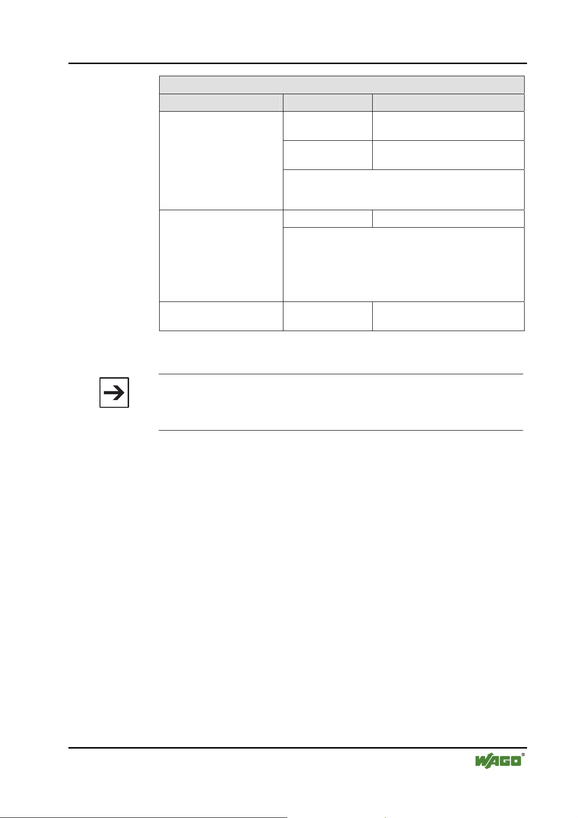
1.1.2 Personnel Qualifications
The use of the product described in this Manual requires special personnel
qualifications, as shown in the following table:
Activity Electrical specialist
Assembly
Commissioning
Programming
Maintenance
Troubleshooting
X X
X X
X
X X
X
Instructed
personnel*)
Specialists**) having
qualifications in PLC
programming
Disassembly
*) Instructed persons have been trained by qualified personnel or electrical specialists.
**) A specialist is a person, who – thanks to technical training – has the qualification, know ledge and expertise to meet the required specifications of this work and to identify any po tential hazardous situation in the above listed fields of activity.
WAGO-I/O-SYSTEM 750
PROFINET IO
X X
Page 10

10 • Important Notes
Legal Bases
All responsible persons have to familiarize themselves with the underlying
legal standards to be applied. WAGO Kontakttechnik GmbH & Co. KG does
not assume any liability whatsoever resulting from improper handling and
damage incurred to both WAGO´s own and third-party products by
disregarding detailed information in this Manual.
1.1.3 Use of the 750 Series in Compliance with Underlying
Provisions
Couplers, controllers and I/O modules found in the modular WAGO-I/OSYSTEM 750 receive digital and analog signals from sensors and transmit
them to the actuators or higher-level control systems. Using programmable
controllers, the signals can also be (pre-)processed.
The components have been developed for use in an environment that meets
the IP20 protection class criteria. Protection against finger injury and solid
impurities up to 12.5 mm diameter is assured; protection against water damage
is not ensured. Unless otherwise specified, operation of the components in wet
and dusty environments is prohibited.
1.1.4 Technical Condition of Specified Devices
The components to be supplied Ex Works, are equipped with hardware and
software configurations, which meet the individual application requirements.
Changes in hardware, software and firmware are permitted exclusively within
the framework of the various alternatives that are documented in the specific
manuals. WAGO Kontakttechnik GmbH & Co. KG will be exempted from
any liability in case of changes in hardware or software as well as to noncompliant usage of components.
Please send your request for modified and new hardware or software
configurations directly to WAGO Kontakttechnik GmbH & Co. KG.
WAGO-I/O-SYSTEM 750
PROFINET IO
Page 11

Important Notes • 11 Standards and Guidelines for Operating the 750 Series
1.2 Standards and Guidelines for Operating the 750 Series
Please adhere to the standards and guidelines required for the use of your
system:
• The data and power lines shall be connected and installed in compliance
with the standards required to avoid failures on your system and to
substantially minimize any imminently hazardous situations resulting in
personal injury.
• For assembly, start-up, maintenance and troubleshooting, adhere to the
specific accident prevention provisions which apply to your system (e.g.
BGV A 3, "Electrical Installations and Equipment").
• Emergency stop functions and equipment shall not be made ineffective.
See relevant standards (e.g. DIN EN 418).
• The equipment of your system shall be conform to EMC guidelines so that
any electromagnetic interferences will be eliminated.
• Operating 750 Series components in home applications without further
measures is permitted only if they meet the emission limits (emissions of
interference) in compliance with EN 61000-6-3. You will find the detailed
information in section "WAGO-I/O-SYSTEM 750" ! "System
Description" ! "Technical Data".
• Please observe the safety precautions against electrostatic discharge in
accordance with DIN EN 61340-5-1/-3. When handling the modules,
please ensure that environmental factors (persons, working place and
packaging) are well grounded.
• The valid standards and guidelines applicable for the installation of switch
cabinets shall be adhered to.
WAGO-I/O-SYSTEM 750
PROFINET IO
Page 12
12 • Important Notes Symbols
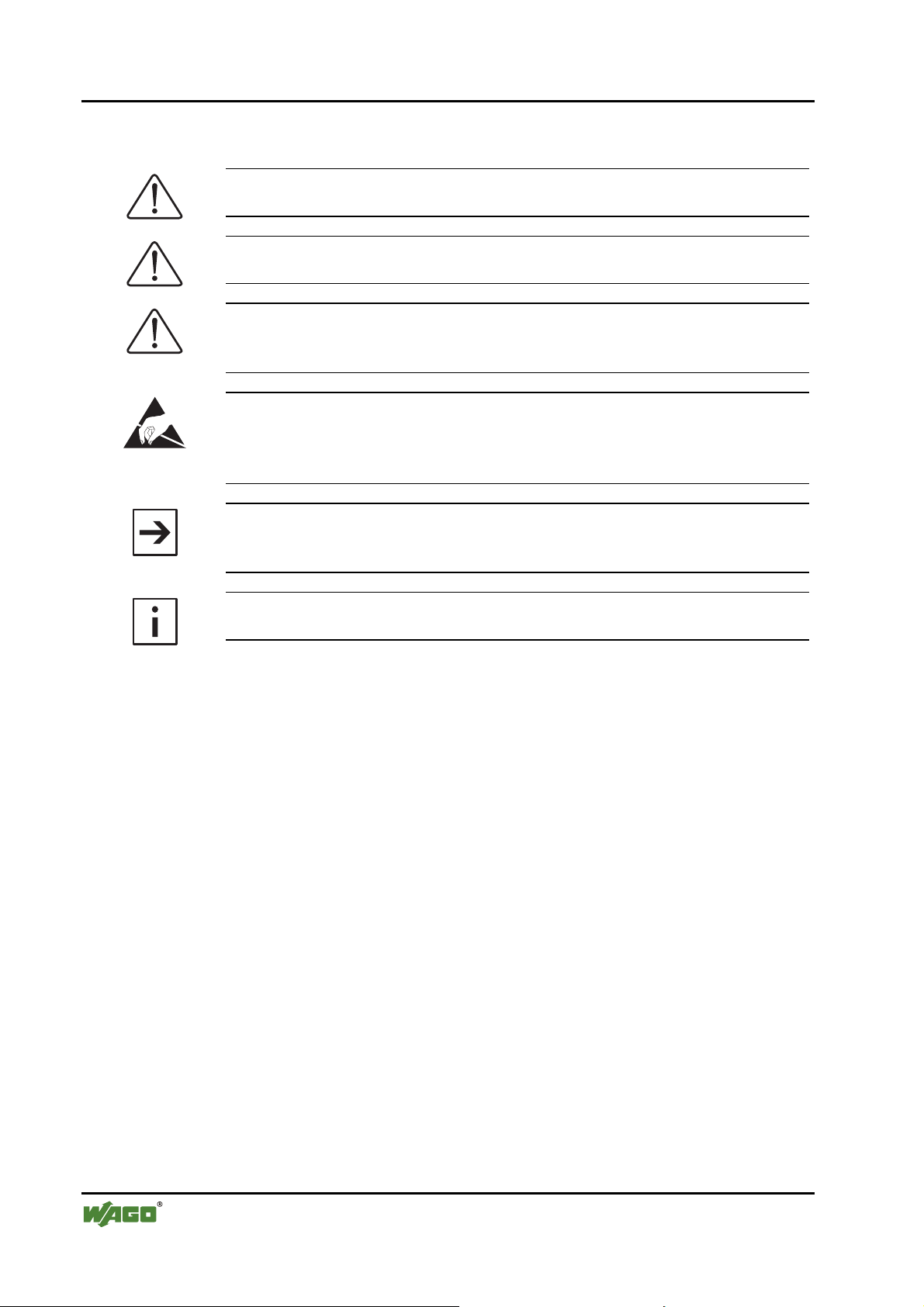
1.3 Symbols
Danger
Always observe this information to protect persons from injury.
Warning
Always observe this information to prevent damage to the device.
Attention
Marginal conditions that must always be observed to ensure smooth and
efficient operation.
ESD (Electrostatic Discharge)
Warning of damage to the components through electrostatic discharge.
Observe the precautionary measure for handling components at risk of
electrostatic discharge.
Note
Make important notes that are to be complied with so that a trouble-free and
efficient device operation can be guaranteed.
Additional Information
References to additional literature, manuals, data sheets and internet pages.
WAGO-I/O-SYSTEM 750
PROFINET IO
Page 13
Important Notes • 13
Safety Information
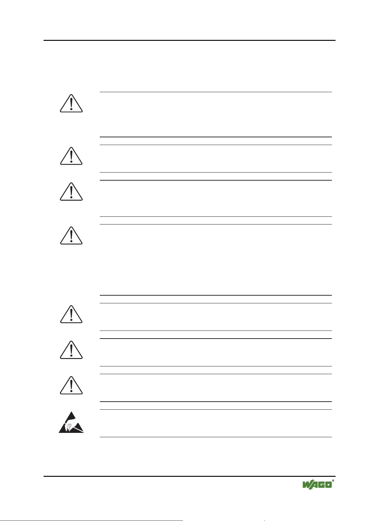
1.4 Safety Information
When connecting the device to your installation and during operation, the
following safety notes must be observed:
Danger
The WAGO-I/O-SYSTEM 750 and its components are an open system. It
must only be assembled in housings, cabinets or in electrical operation
rooms. Access is only permitted via a key or tool to authorized qualified
personnel.
Danger
All power sources to the device must always be switched off before carrying
out any installation, repair or maintenance work.
Warning
Replace defective or damaged device/module (e.g. in the event of deformed
contacts), as the functionality of field bus station in question can no longer be
ensured on a long-term basis.
Warning
The components are not resistant against materials having seeping and
insulating properties. Belonging to this group of materials is: e.g. aerosols,
silicones, triglycerides (found in some hand creams). If it cannot be ruled out
that these materials appear in the component environment, then the
components must be installed in an enclosure that is resistant against the
above mentioned materials. Clean tools and materials are generally required
to operate the device/module.
Warning
Soiled contacts must be cleaned using oil-free compressed air or with ethyl
alcohol and leather cloths.
Warning
Do not use contact sprays, which could possibly impair the functioning of the
contact area.
Warning
Avoid reverse polarity of data and power lines, as this may damage the
devices.
ESD (Electrostatic Discharge)
The devices are equipped with electronic components that may be destroyed
by electrostatic discharge when touched.
WAGO-I/O-SYSTEM 750
PROFINET IO
Page 14
14 • Important Notes
Font Conventions
Warning
For components with ETHERNET/RJ-45 connectors:
Only for use in LAN, not for connection to telecommunication circuits.
1.5 Font Conventions
italic
Names of paths and data files are marked in italic-type.
e.g.: C:\Programs\WAGO-IO-CHECK
italic
Menu items are marked in italic-type, bold letters.
e.g.: Save
\
A backslash between two names characterizes the selection of a
menu point from a menu.
e.g.: File \ New
END
Pushbuttons are marked as bold with small capitals
e.g.: ENTER
< >
Keys are marked bold within angle brackets
e.g.: <F5>
Courier
The print font for program codes is Courier.
e.g.: END_VAR
1.6 Number Notation
Number code Example Note
Decimal 100 Normal notation
Hexadecimal 0x64 C notation
Binary '100'
'0110.0100'
In quotation marks,
nibble separated with dots (.)
1.7 Scope
This manual describes the field bus independent WAGO-I/O-SYSTEM 750
with the fieldbus coupler for PROFINET IO.
Item-No. Description
750-370 Fieldbus Coupler PROFINET IO
WAGO-I/O-SYSTEM 750
PROFINET IO
Page 15

Important Notes • 15 Abbreviation
1.8 Abbreviation
AI
AO
CPU
DI
DO
I/O
ID
HB
LB
PLC
SW
Analog Input
Analog Input Module
Analog Output
Analog Input Module
In this case the Run Time System for the eradication of the user
program in the PFC
Digital Input
Digital Input Module
Digital Output
Digital Output Module
Input/Output
Identifier
High Byte
Low Byte
Programmable Logic Controller
Software Version
WAGO-I/O-SYSTEM 750
PROFINET IO
Page 16
16 • The WAGO-I/O-SYSTEM 750
System Description
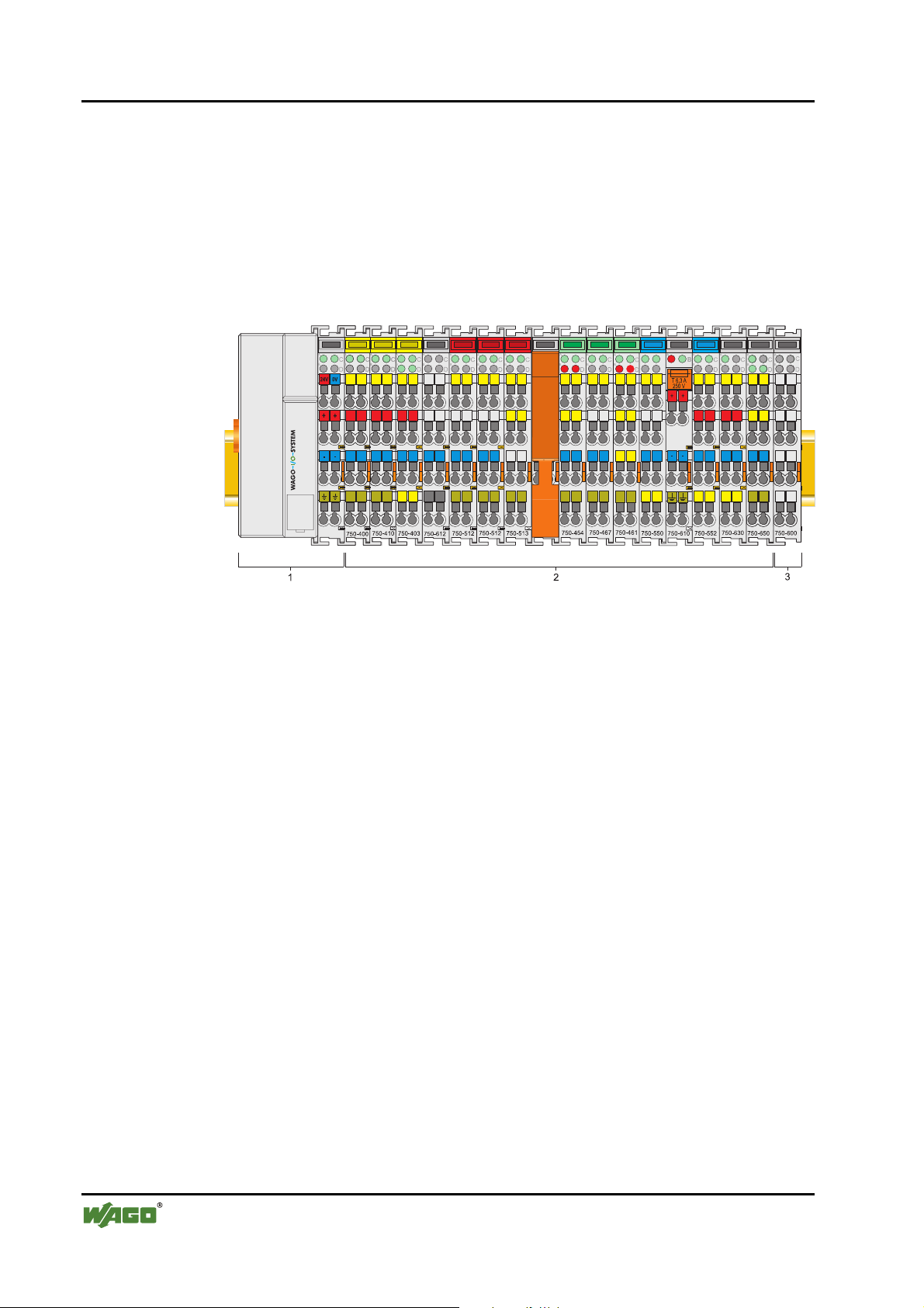
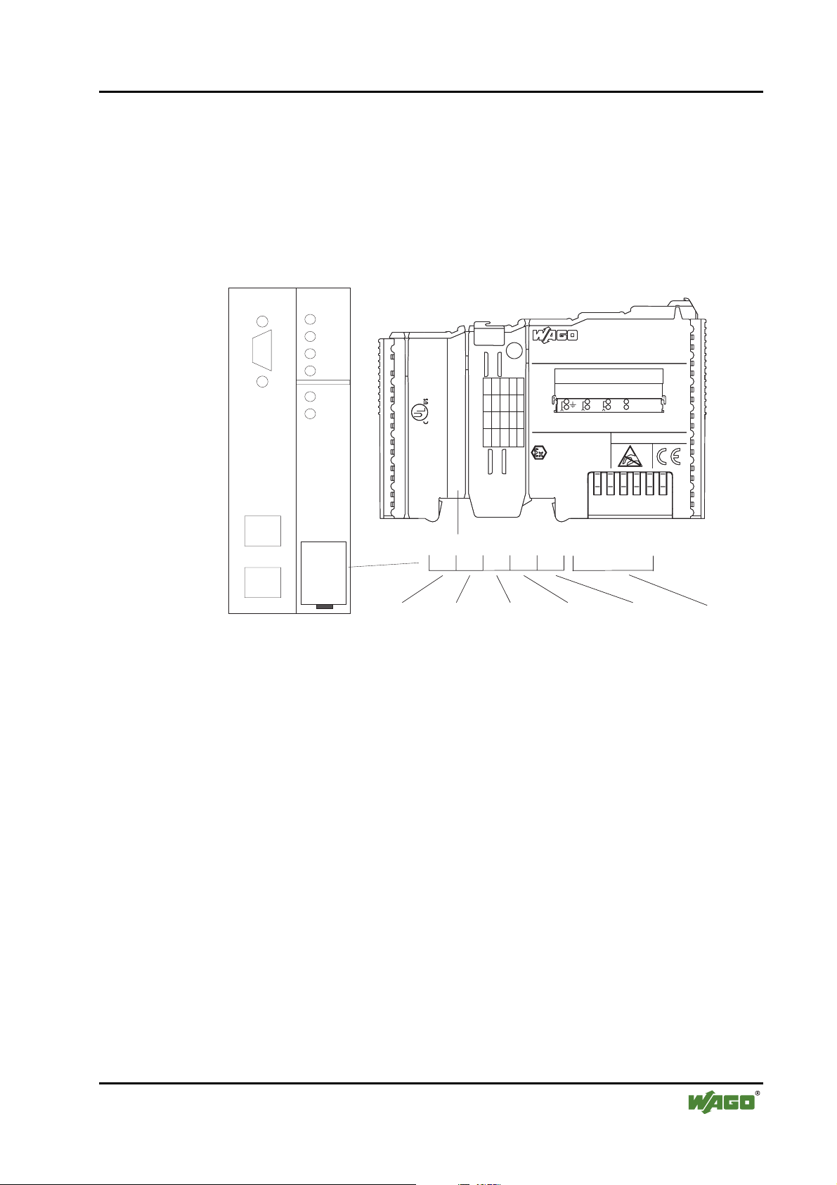
2 The WAGO-I/O-SYSTEM 750
2.1 System Description
The WAGO-I/O-SYSTEM 750 is a modular, field bus independent I/O
system. It is comprised of a field bus coupler/controller (1) and connected
field bus modules (2) for any type of signal. Together, these make up the field
bus node. The end module (3) completes the node.
Fig. 2-1: Field bus node g0xxx00x
Couplers/controllers for field bus systems such as PROFIBUS, INTERBUS,
ETHERNET TCP/IP, CAN (CANopen, DeviceNet, CAL), MODBUS, LON
and others are available.
The coupler/controller contains the field bus interface, electronics and a power
supply terminal. The field bus interface forms the physical interface to the
relevant field bus. The electronics process the data of the bus modules and
make it available for the field bus communication. The 24 V system supply
and the 24 V field supply are fed in via the integrated power supply terminal.
The field bus coupler communicates via the relevant field bus. The
programmable field bus controller (PFC) enables the implementation of
additional PLC functions. Programming is done with the WAGO I/O PRO
CAA in accordance with IEC 61131-3.
Bus modules for diverse digital and analog I/O functions as well as special
functions can be connected to the coupler/controller. The communication
between the coupler/controller and the bus modules is carried out via an
internal bus.
The WAGO-I/O-SYSTEM 750 has a clear port level with LEDs for status
indication, insertable mini WSB markers and pullout group marker carriers.
The 3-wire technology supplemented by a ground wire connection allows for
direct sensor/actuator wiring.
WAGO-I/O-SYSTEM 750
PROFINET IO
Page 17
The WAGO-I/O-SYSTEM 750 • 17 Technical Data
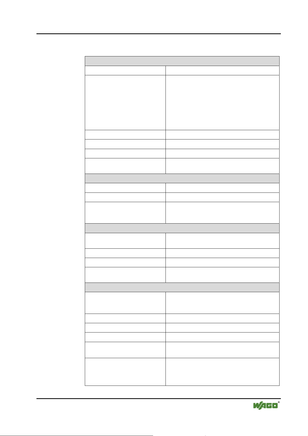
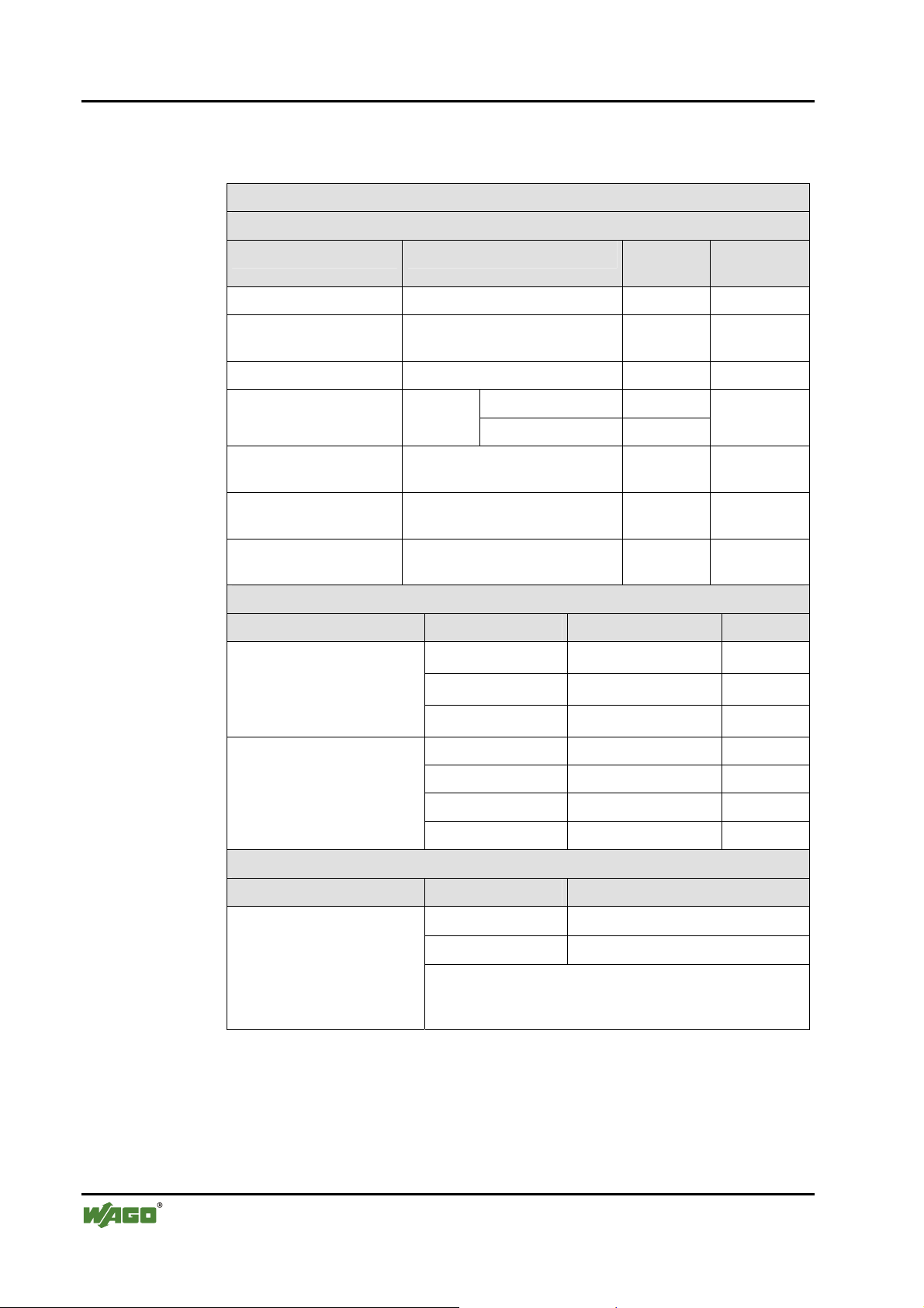
2.2 Technical Data
Mechanic
Material Polycarbonate, Polyamide 6.6
Dimensions W x H* x L
* from upper edge of DIN 35 rail
- Coupler/Controller (Standard)
- Coupler/Controller (ECO)
- Coupler/Controller (FireWire)
- I/O module, single
- I/O module, double
- I/O module, fourfold
- 51 mm x 65 mm x 100 mm
- 50 mm x 65 mm x 100 mm
- 62 mm x 65 mm x 100 mm
- 12 mm x 64 mm x 100 mm
- 24 mm x 64 mm x 100 mm
- 48 mm x 64 mm x 100 mm
Installation on DIN 35 with interlock
Modular by double feather key dovetail
Mounting position any position
Marking standard marking label type
group marking label 8 x 47 mm
Connection
Connection type CAGE CLAMP®
Wire range 0.08 mm² ... 2.5 mm², AWG 28-14
Stripped length 8 … 9 mm,
9 … 10 mm for components with pluggable wiring
(753-xxx)
Contacts
Power jumpers contacts blade/spring contact
self-cleaning
Current via power contacts
Voltage drop at I
< 1 V/64 modules
max
10 A
max
Data contacts slide contact, hard gold plated
1.5 µm, self-cleaning
Climatic environmental conditions
Operating temperature 0 °C ... 55 °C,
-20 °C … +60 °C for components with extended
temperature range (750-xxx/025-xxx)
Storage temperature -20 °C ... +85 °C
Relative humidity 5 % … 95 % without condensation
Resistance to harmful substances acc. to IEC 60068-2-42 and IEC 60068-2-43
Maximum pollutant concentration at
relative humidity < 75%
≤ 25 ppm
SO
2
H
S ≤ 10 ppm
2
Special conditions Ensure that additional measures for components are
taken, which are used in an environment involving:
– dust, caustic vapors or gases
– ionization radiation
WAGO-I/O-SYSTEM 750
PROFINET IO
Page 18
18 • The WAGO-I/O-SYSTEM 750
Technical Data
Safe electrical isolation
Air and creepage distance acc. to IEC 60664-1
Degree of pollution
2
acc. To IEC 61131-2
Degree of protection
Degree of protection IP 20
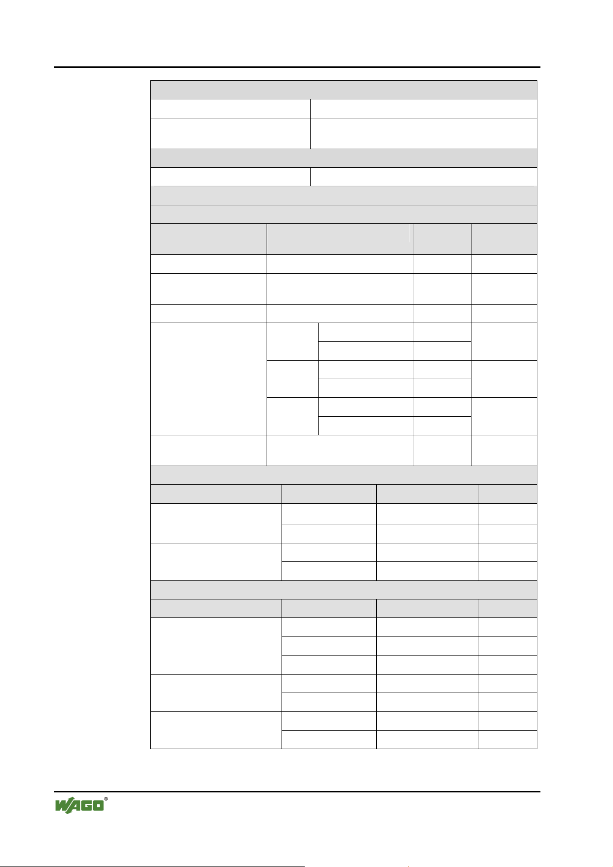
Electromagnetic compatibility
Immunity to interference for industrial areas acc. to EN 61000-6-2 (2001)
Test specification Test values Strength
class
Evaluation
criteria
EN 61000-4-2 ESD 4 kV/8 kV (contact/air) 2/3 B
EN 61000-4-3
10 V/m 80 MHz ... 1 GHz 3 A
electromagnetic fields
EN 61000-4-4 burst 1 kV/2 kV (data/supply) 2/3 B
EN 61000-4-5 surge
-/- (line/line) Data:
B
1 kV (line/earth) 2
supply:
AC
supply:
0.5 kV (line/line) 1 DC
0.5 kV (line/earth) 1
1 kV (line/line) 2
2 kV (line/earth) 3
B
B
EN 61000-4-6
RF disturbances
10 V/m 80 % AM
(0.15 ... 80 MHz)
3 A
Emission of interference for industrial areas acc. to EN 61000-6-4 (2001)
Test specification Limit values/[QP]*) Frequency range Distance
79 dB (µV) 150 kHz ... 500 kHz EN 55011 (AC supply,
conducted)
73 dB (µV) 500 kHz ... 30 MHz
40 dB (µV/m) 30 MHz ... 230 MHz 10 m EN 55011 (radiated)
47 dB (µV/m) 230 MHz ... 1 GHz 10 m
Emission of interference for residential areas acc. to EN 61000-6-3 (2001)
Test specification Limit values/[QP]*) Frequency range Distance
EN 55022 (AC supply,
conducted)
66 ... 56 dB (µV) 150 kHz ... 500 kHz
56 dB (µV) 500 kHz ... 5 MHz
60 dB (µV) 5 MHz ... 30 MHz
40 ... 30 dB (µA) 150 kHz ... 500 kHz EN 55022 (DC supply/data,
conducted)
30 dB (µA) 500 kHz ... 30 MHz
30 dB (µV/m) 30 MHz ... 230 MHz 10 m EN 55022 (radiated)
37 dB (µV/m) 230 MHz ... 1 GHz 10 m
WAGO-I/O-SYSTEM 750
PROFINET IO
Page 19
The WAGO-I/O-SYSTEM 750 • 19
Technical Data
Mechanical strength acc. to IEC 61131-2
Test specification Frequency range Limit value
IEC 60068-2-6 vibration
IEC 60068-2-32 free fall 1 m
*) QP: Quasi Peak
5 Hz ≤ f < 9 Hz
9 Hz ≤ f < 150 Hz
Note on vibration test:
a) Frequency change: max. 1 octave/minute
b) Vibration direction: 3 axes
15 g IEC 60068-2-27 shock
Note on shock test:
a) Type of shock: half sine
b) Shock duration: 11 ms
c) Shock direction: 3x in positive and 3x in negative
direction for each of the three mutually perpendicular axes
of the test specimen
1.75 mm amplitude (permanent)
3.5 mm amplitude (short term)
0.5 g (permanent)
1 g (short term)
(module in original packing)
Note
If the technical data of components differ from the values described here, the
technical data shown in the manuals of the respective components shall be
valid.
WAGO-I/O-SYSTEM 750
PROFINET IO
Page 20
20 • The WAGO-I/O-SYSTEM 750
Technical Data
For Products of the WAGO-I/O-SYSTEM 750 with ship specific approvals
supplementary guidelines are valid:
Electromagnetic compatibility
Immunity to interference acc. to Germanischer Lloyd (2003)
Test specification Test values Strength
class
IEC 61000-4-2 ESD 6 kV/8 kV (contact/air) 3/3 B
IEC 61000-4-3
electromagnetic fields
IEC 61000-4-4 burst 1 kV/2 kV (data/supply) 2/3 A
IEC 61000-4-6
RF disturbances
Type test AF disturbances
(harmonic waves)
Type test high voltage 755 V DC
Emission of interference acc. to Germanischer Lloyd (2003)
Test specification Limit values Frequency range Distance
Type test
(EMC1, conducted)
allows for ship bridge control
applications
10 V/m 80 MHz ... 2 GHz 3 A
0.5 kV (line/line) 1 IEC 61000-4-5 surge AC/DC
Supply:
10 V/m 80 % AM
(0.15 ... 80 MHz)
3 V, 2 W - A
1500 V AC
96 ... 50 dB (µV) 10 kHz ... 150 kHz
60 ... 50 dB (µV) 150 kHz ... 350 kHz
50 dB (µV) 350 kHz ... 30 MHz
1 kV (line/earth) 2
3 A
- -
Evaluation
criteria
A
Type test
(EMC1, radiated)
allows for ship bridge control
applications
except: 24 dB (µV/m) 156 MHz ... 165 MHz 3 m
Mechanical strength acc. to Germanischer Lloyd (2003)
Test specification Frequency range Limit value
IEC 60068-2-6 vibration
(category A – D)
80 ... 52 dB (µV/m) 150 kHz ... 300 kHz 3 m
52 ... 34 dB (µV/m) 300 kHz ... 30 MHz 3 m
54 dB (µV/m) 30 MHz ... 2 GHz 3 m
2 Hz ≤ f < 25 Hz
25 Hz ≤ f < 100 Hz
Note on vibration test:
a) Frequency change: max. 1 octave/minute
b) Vibration direction: 3 axes
± 1.6 mm amplitude (permanent)
4 g (permanent)
WAGO-I/O-SYSTEM 750
PROFINET IO
Page 21
The WAGO-I/O-SYSTEM 750 • 21
Technical Data
Range of
application
Industrial areas EN 61000-6-4 (2001) EN 61000-6-2 (2001)
Residential areas EN 61000-6-3 (2001)*) EN 61000-6-1 (2001)
*)
The system meets the requirements on emission of interference in residential areas with
the field bus coupler/controller for:
ETHERNET
LonWorks
CANopen
DeviceNet
MODBUS
KNX
BACnet
With a special permit, the system can also be implemented with other field bus
couplers/controllers in residential areas (housing, commercial and business areas, smallscale enterprises). The special permit can be obtained from an authority or inspection
office. In Germany, the Federal Office for Post and Telecommunications and its branch
offices issues the permit.
It is possible to use other field bus couplers/controllers under certain boundary
conditions. Please contact WAGO Kontakttechnik GmbH & Co. KG.
Required specification
emission of interference
750-342/-841/-842/-860
750-319/-819
750-337/-837
750-306/-806
750-312/-314/ -315/ -316
750-812/-814/ -815/ -816
750-849
750-830
Required specification
immunity to interference
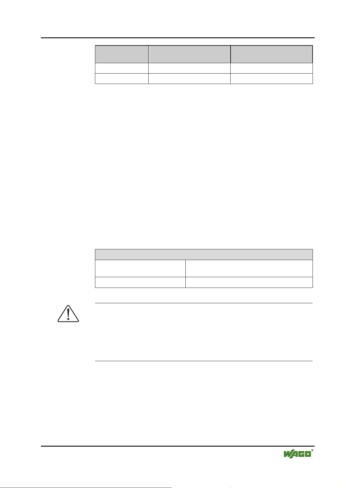
Maximum power dissipation of the components
Bus modules 0.8 W / bus terminal (total power dissipation,
system/field)
Field bus coupler/controller 2.0 W / coupler/controller
Warning
The power dissipation of all installed components must not exceed the
maximum conductible power of the housing (cabinet).
When dimensioning the housing, care is to be taken that even under high
external temperatures, the temperature inside the housing does not exceed the
permissible ambient temperature of 55 °C.
WAGO-I/O-SYSTEM 750
PROFINET IO
Page 22
22 • The WAGO-I/O-SYSTEM 750
Technical Data
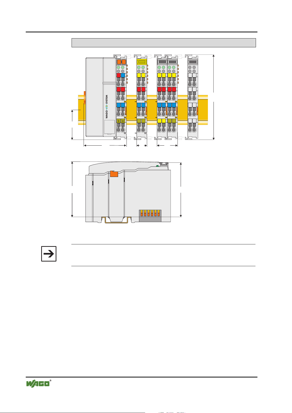
Dimensions
02
01
35
A
B
24V 0V
+
-
A
C
B
D
+
A
C
D
A
C
B
B
D
A
C
D
C
B
D
100
-
51
65
Side view
12
24
Dimensions in mm
64
Fig. 2-2: Dimensions g01xx05e
Note
The illustration shows a standard coupler. For detailed dimensions, please
refer to the technical data of the respective coupler/controller.
WAGO-I/O-SYSTEM 750
PROFINET IO
Page 23
The WAGO-I/O-SYSTEM 750 • 23
Manufacturing Number
2.3 Manufacturing Number
The manufacturing number indicates the delivery status directly after
production.
This number is part of the lateral marking on the component.
In addition, starting from calendar week 43/2000 the manufacturing number is
also printed on the cover of the configuration and programming interface of
the field bus coupler or controller.
PROFIBUS
ITEM-NO.:750-333
ITEM-NO.:750-333
PROFIBUS DP 12 MBd /DPV1
PROFIBUS DP 12 MBd /DPV1
-
Power Supply
Field
24 V
+
0V
0V
Power Supply
Power Supply
Electronic
Electronic
PATENTS PENDING
PATENTS PENDING
750-333
Hansastr. 27
Hansastr. 27
GL
D-32423 Minden
D-32423 Minden
24V DC
24V DC
AWG 28-14
AWG 28-14
55°C max ambient
55°C max ambient
72072
72072
DS
NO
SW
HW
FWL
II3GD
LISTED 22ZA AND 22XM
LISTED 22ZA AND 22XM
0103000203-B000000
0103000203-B060606
II3GD
DEMKO 02 ATEX132273 X
DEMKO 02 ATEX132273 X
EEx nA II T4
EEx nA II T4
WAGO - I/O - SYSTEM
Manufacturing Number
0
1
3
01030002
03-B
060606
72072
Calendar
week
Fig. 2-3: Example: Manufacturing Number of a PROFIBUS field bus coupler 750-333
0
Year Software
version
2
0
0
0
0
3
-B060606
Hardware
Firmware Loader
version
version
Internal
Number
g01xx15e
The manufacturing number consists of the production week and year, the
software version (if available), the hardware version of the component, the
firmware loader (if available) and further internal information for
WAGO Kontakttechnik GmbH & Co. KG.
WAGO-I/O-SYSTEM 750
PROFINET IO
Page 24

24 • The WAGO-I/O-SYSTEM 750
Component Update
2.4 Component Update
For the case of an Update of one component, the lateral marking on each
component contains a prepared matrix.
This matrix makes columns available for altogether three updates to the entry
of the current update data, like production order number (NO; starting from
calendar week 13/2004), update date (DS), software version (SW), hardware
version (HW) and the firmware loader version (FWL, if available).
Update Matrix
Current Version data for: 1. Update 2. Update 3. Update
Production Order
Number
Datestamp
Software index
Hardware index
Firmware loader
index
NO
DS
SW
HW
FWL
" only starting from calendar
" only for coupler/controller
If the update of a component took place, the current version data are registered
into the columns of the matrix.
Additionally with the update of a field bus coupler or controller also the cover
of the configuration and programming interface of the coupler or controller is
printed on with the current manufacturing and production order number.
The original manufacturing data on the housing of the component remain
thereby.
2.5 Storage, Assembly and Transport
Wherever possible, the components are to be stored in their original
packaging. Likewise, the original packaging provides optimal protection
during transport.
week 13/2004
When assembling or repacking the components, the contacts must not be
soiled or damaged. The components must be stored and transported in
appropriate containers/packaging. Thereby, the ESD information is to be
regarded.
Statically shielded transport bags with metal coatings are to be used for the
transport of open components for which soiling with amine, amide and
silicone has been ruled out, e.g. 3M 1900E.
WAGO-I/O-SYSTEM 750
PROFINET IO
Page 25
The WAGO-I/O-SYSTEM 750 • 25
Mechanical Setup
2.6 Mechanical Setup
2.6.1 Installation Position
Along with horizontal and vertical installation, all other installation positions
are allowed.
Attention
2.6.2 Total Expansion
In the case of vertical assembly, an end stop has to be mounted as an
additional safeguard against slipping.
WAGO item 249-116 End stop for DIN 35 rail, 6 mm wide
WAGO item 249-117 End stop for DIN 35 rail, 10 mm wide
The length of the module assembly (including one end module of 12mm
width) that can be connected to the coupler/controller is 780 mm. When
assembled, the I/O modules have a maximum length of 768 mm.
Examples:
• 64 I/O modules of 12 mm width can be connected to one
coupler/controller.
• 32 I/O modules of 24 mm width can be connected to one
coupler/controller.
Exception:
The number of connected I/O modules also depends on which type of
coupler/controller is used. For example, the maximum number of I/O modules
that can be connected to a PROFIBUS coupler/controller is 63 without end
module. The maximum total expansion of a node is calculated as follows:
Warning
The maximum total length of a node without coupler/controller must not
exceed 780 mm. Furthermore, restrictions made on certain types of
couplers/controllers must be observed (e.g. for PROFIBUS).
WAGO-I/O-SYSTEM 750
PROFINET IO
Page 26

26 • The WAGO-I/O-SYSTEM 750
Mechanical Setup
2.6.3 Assembly onto Carrier Rail
2.6.3.1 Carrier Rail Properties
All system components can be snapped directly onto a carrier rail in
accordance with the European standard EN 50022 (DIN 35).
Warning
WAGO Kontakttechnik GmbH & Co. KG supplies standardized carrier rails
that are optimal for use with the I/O system. If other carrier rails are used,
then a technical inspection and approval of the rail by WAGO
Kontakttechnik GmbH & Co. KG should take place.
Carrier rails have different mechanical and electrical properties. For the
optimal system setup on a carrier rail, certain guidelines must be observed:
• The material must be non-corrosive.
• Most components have a contact to the carrier rail to ground electro-
magnetic disturbances. In order to avoid corrosion, this tin-plated carrier
rail contact must not form a galvanic cell with the material of the carrier
rail which generates a differential voltage above 0.5 V (saline solution of
0.3% at 20°C) .
• The carrier rail must optimally support the EMC measures integrated into
the system and the shielding of the bus module connections.
• A sufficiently stable carrier rail should be selected and, if necessary,
several mounting points (every 20 cm) should be used in order to prevent
bending and twisting (torsion).
• The geometry of the carrier rail must not be altered in order to secure the
safe hold of the components. In particular, when shortening or mounting
the carrier rail, it must not be crushed or bent.
• The base of the I/O components extends into the profile of the carrier rail.
For carrier rails with a height of 7.5 mm, mounting points are to be riveted
under the node in the carrier rail (slotted head captive screws or blind
rivets).
WAGO-I/O-SYSTEM 750
PROFINET IO
Page 27
The WAGO-I/O-SYSTEM 750 • 27
Mechanical Setup
2.6.3.2 WAGO DIN Rail
WAGO carrier rails meet the electrical and mechanical requirements.
Item Number Description
210-113 /-112 35 x 7.5; 1 mm; steel yellow chromated; slotted/unslotted
210-114 /-197 35 x 15; 1.5 mm; steel yellow chromated; slotted/unslotted
210-118 35 x 15; 2.3 mm; steel yellow chromated; unslotted
210-198 35 x 15; 2.3 mm; copper; unslotted
210-196 35 x 7.5; 1 mm; aluminum; unslotted
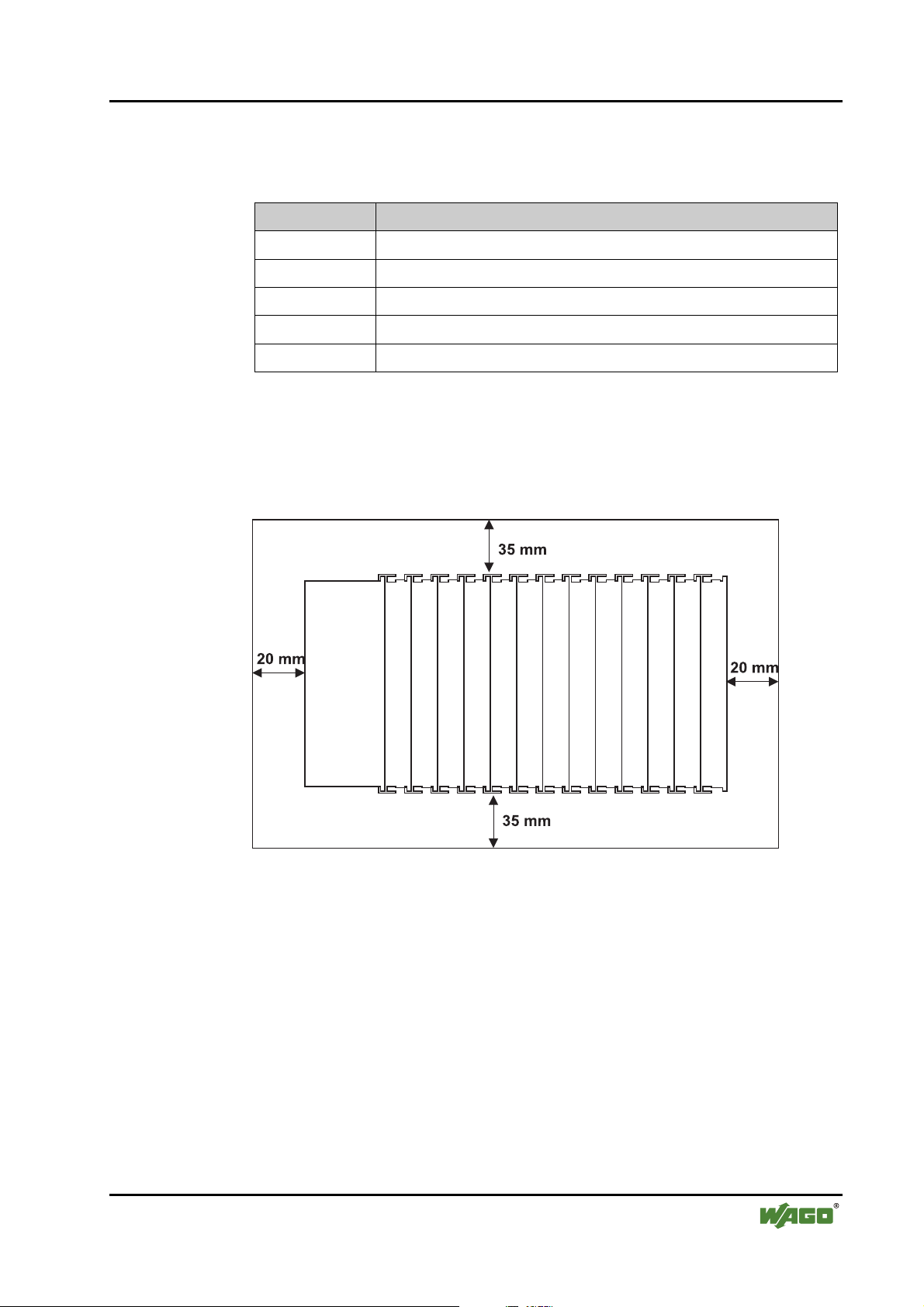
2.6.4 Spacing
The spacing between adjacent components, cable conduits, casing and frame
sides must be maintained for the complete field bus node.
Fig. 2-4: Spacing g01xx13x
The spacing creates room for heat transfer, installation or wiring. The spacing
to cable conduits also prevents conducted electromagnetic interferences from
influencing the operation.
WAGO-I/O-SYSTEM 750
PROFINET IO
Page 28
28 • The WAGO-I/O-SYSTEM 750
Mechanical Setup
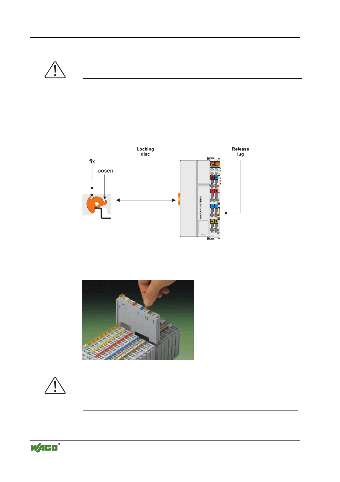
2.6.5 Plugging and Removal of the Components
Warning
Before work is done on the components, the voltage supply must be turned off.
In order to safeguard the coupler/controller from jamming, it should be fixed
onto the carrier rail with the locking disc To do so, push on the upper groove
of the locking disc using a screwdriver.
To pull out the field bus coupler/controller, release the locking disc by
pressing on the bottom groove with a screwdriver and then pulling the orange
colored unlocking lug .
Fig. 2-5: Coupler/Controller and unlocking lug g01xx12e
It is also possible to release an individual I/O module from the unit by pulling
an unlocking lug.
Fig. 2-6: removing bus terminal p0xxx01x
Danger
Ensure that an interruption of the PE will not result in a condition which
could endanger a person or equipment!
For planning the ring feeding of the ground wire, please see chapter 2.6.3.
WAGO-I/O-SYSTEM 750
PROFINET IO
Page 29
The WAGO-I/O-SYSTEM 750 • 29
Mechanical Setup
2.6.6 Assembly Sequence
All system components can be snapped directly on a carrier rail in accordance
with the European standard EN 50022 (DIN 35).
The reliable positioning and connection is made using a tongue and groove
system. Due to the automatic locking, the individual components are securely
seated on the rail after installing.
Starting with the coupler/controller, the bus modules are assembled adjacent
to each other according to the project planning. Errors in the planning of the
node in terms of the potential groups (connection via the power contacts) are
recognized, as the bus modules with power contacts (male contacts) cannot be
linked to bus modules with fewer power contacts.
Attention
Always link the bus modules with the coupler/controller, and always plug
from above.
Warning
Never plug bus modules from the direction of the end terminal. A ground
wire power contact, which is inserted into a terminal without contacts, e.g. a
4-channel digital input module, has a decreased air and creepage distance to
the neighboring contact in the example DI4.
Always terminate the field bus node with an end module (750-600).
WAGO-I/O-SYSTEM 750
PROFINET IO
Page 30
30 • The WAGO-I/O-SYSTEM 750
Mechanical Setup
2.6.7 Internal Bus/Data Contacts
Communication between the coupler/controller and the bus modules as well as
the system supply of the bus modules is carried out via the internal bus. It is
comprised of 6 data contacts, which are available as self-cleaning gold spring
contacts.
Fig. 2-7: Data contacts p0xxx07x
Warning
Do not touch the gold spring contacts on the I/O modules in order to avoid
soiling or scratching!
ESD (Electrostatic Discharge)
The modules are equipped with electronic components that may be destroyed
by electrostatic discharge. When handling the modules, ensure that the
environment (persons, workplace and packing) is well grounded. Avoid
touching conductive components, e.g. data contacts.
WAGO-I/O-SYSTEM 750
PROFINET IO
Page 31

The WAGO-I/O-SYSTEM 750 • 31
Mechanical Setup
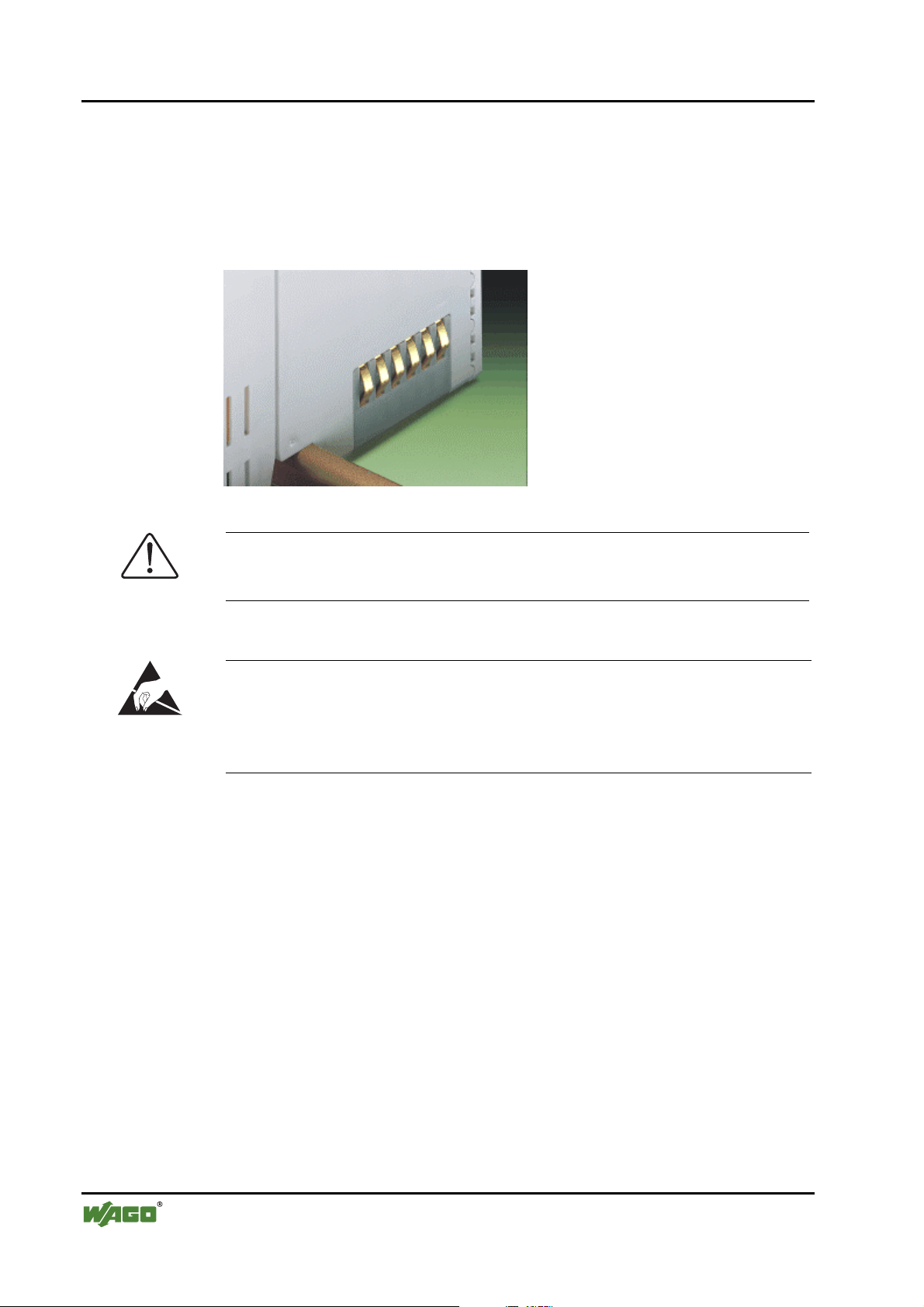
2.6.8 Power Contacts
Self-cleaning power contacts , are situated on the side of the components
which further conduct the supply voltage for the field side. These contacts
come as touchproof spring contacts on the right side of the coupler/controller
and the bus module. As fitting counterparts the module has male contacts on
the left side.
Danger
The male contacts are sharp-edged. Handle the module carefully to prevent
injury.
Attention
Please take into consideration that some bus modules have no or only a few
power jumper contacts. The design of some modules does not allow them to
be physically assembled in rows, as the grooves for the male contacts are
closed at the top.
Fig. 2-8: Example for the arrangement of power contacts g0xxx05e
Recommendation
With the WAGO ProServe® Software smartDESIGNER, the structure of a
field bus node can be configured. The configuration can be tested via the
integrated accuracy check.
WAGO-I/O-SYSTEM 750
PROFINET IO
Page 32

32 • The WAGO-I/O-SYSTEM 750
Mechanical Setup
2.6.9 Wire Connection
All components have CAGE CLAMP® connections.
The WAGO CAGE CLAMP® connection is appropriate for solid, stranded
and finely stranded conductors. Each clamping unit accommodates one
conductor.
Fig. 2-9: CAGE CLAMP® Connection g0xxx08x
The operating tool is inserted into the opening above the connection. This
opens the CAGE CLAMP®. Subsequently the conductor can be inserted into
the opening. After removing the operating tool, the conductor is safely
clamped.
More than one conductor per connection is not permissible. If several
conductors have to be made at one connection point, then they should be made
away from the connection point using WAGO Terminal Blocks. The terminal
blocks may be jumpered together and a single wire brought back to the I/O
module connection point.
Attention
If it is unavoidable to jointly connect 2 conductors, then a ferrule must be used
to join the wires together.
Ferrule:
Length 8 mm
Nominal cross section
1 mm2 for 2 conductors with 0.5 mm2 each
max.
WAGO Product 216-103 or products with comparable properties
WAGO-I/O-SYSTEM 750
PROFINET IO
Page 33

The WAGO-I/O-SYSTEM 750 • 33 Power Supply
2.7 Power Supply
2.7.1 Isolation
Within the field bus node, there are three electrically isolated potentials.
• Operational voltage for the field bus interface.
• Electronics of the couplers/controllers and the bus modules (internal bus).
• All bus modules have an electrical isolation between the electronics
(internal bus, logic) and the field electronics. Some digital and analog input
modules have each channel electrically isolated, please see catalog.
Fig. 2-10: Isolation g0xxx01e
Attention
The ground wire connection must be present in each group. In order that all
protective conductor functions are maintained under all circumstances, it is
recommended that a ground wire be connected at the beginning and end of a
potential group. (ring format, please see chapter 2.8.3). Thus, if a bus module
comes loose from a composite during servicing, then the protective conductor
connection is still guaranteed for all connected field devices.
When using a joint power supply unit for the 24 V system supply and the
24 V field supply, the electrical isolation between the internal bus and the
field level is eliminated for the potential group.
WAGO-I/O-SYSTEM 750
PROFINET IO
Page 34

34 • The WAGO-I/O-SYSTEM 750
Power Supply
2.7.2 System Supply
2.7.2.1 Connection
The WAGO-I/O-SYSTEM 750 requires a 24 V direct current system supply
(-15 % or +20 %). The power supply is provided via the coupler/controller
and, if necessary, in addition via the internal system supply modules
(750-613). The voltage supply is reverse voltage protected.
Attention
The use of an incorrect supply voltage or frequency can cause severe damage
to the component.
Fig. 2-11: System Supply g0xxx02e
The direct current supplies all internal system components, e.g.
coupler/controller electronics, field bus interface and bus modules via the
internal bus (5 V system voltage). The 5 V system voltage is electrically
connected to the 24 V system supply.
Fig. 2-12: System Voltage g0xxx06e
WAGO-I/O-SYSTEM 750
PROFINET IO
Page 35

The WAGO-I/O-SYSTEM 750 • 35
f
Power Supply
Attention
Resetting the system by switching on and off the system supply, must take
place simultaneously for all supply modules (coupler/controller and
750-613).
2.7.2.2 Alignment
Recommendation
A stable network supply cannot be taken for granted always and everywhere.
Therefore, regulated power supply units should be used in order to guarantee
the quality of the supply voltage.
The supply capacity of the coupler/controller or the internal system supply
module (750-613) can be taken from the technical data of the components.
Internal current consumption*)
Residual current for bus
terminals*)
*)
cf. catalogue W4 Volume 3, manuals or internet
Example Coupler 750-301:
Current consumption via system voltage:
5 V for electronics of the bus modules and
coupler/controller
Available current for the bus modules. Provided by
the bus power supply unit. See coupler/controller
and internal system supply module (750-613)
internal current consumption:350 mA at 5 V
residual current for
bus modules : 1650 mA at 5 V
sum I
: 2000 mA at 5 V
(5V) total
The internal current consumption is indicated in the technical data for each
bus terminal. In order to determine the overall requirement, add together the
values of all bus modules in the node.
Attention
If the sum of the internal current consumption exceeds the residual current
or bus modules, then an internal system supply module (750-613) must be
placed before the module where the permissible residual current was
exceeded.
WAGO-I/O-SYSTEM 750
PROFINET IO
Page 36

36 • The WAGO-I/O-SYSTEM 750
Power Supply
Example:
A node with a PROFIBUS Coupler 750-333 consists of 20 relay
modules (750-517) and 10 digital input modules (750-405).
Current consumption:
20* 90 mA = 1800 mA
10* 2 mA = 20 mA
Sum 1820 mA
The coupler can provide 1650 mA for the bus modules. Consequently,
an internal system supply module (750-613), e.g. in the middle of the
node, should be added.
Recommendation
With the WAGO ProServe® Software smartDESIGNER, the assembly of a
field bus node can be configured. The configuration can be tested via the
integrated accuracy check.
The maximum input current of the 24 V system supply is 500 mA. The exact
electrical consumption (I
Coupler/Controller
I
= Sum of all the internal current consumption of the connected
(5 V) total
) can be determined with the following formulas:
(24 V)
bus modules
+ internal current consumption coupler/controller
750-613
I
= Sum of all the internal current consumption of the connected
(5 V) total
bus modules
Input current I
(24 V)
=
5 V / 24 V * I
η
= 0.87 (at nominal load)
(5 V) total
/ η
Attention
If the electrical consumption of the power supply point for the 24 V-system
supply exceeds 500 mA, then the cause may be an improperly aligned node
or a defect.
During the test, all outputs, in particular those of the relay modules, must be
active.
WAGO-I/O-SYSTEM 750
PROFINET IO
Page 37

The WAGO-I/O-SYSTEM 750 • 37
Power Supply
2.7.3 Field Supply
2.7.3.1 Connection
Sensors and actuators can be directly connected to the relevant channel of the
bus module in 1/4 conductor connection technology. The bus module supplies
power to the sensors and actuators. The input and output drivers of some bus
modules require the field side supply voltage.
The coupler/controller provides field side power (DC 24V). In this case it is a
passive power supply without protection equipment.
Power supply modules are available for other potentials, e. g. AC 230 V.
Likewise, with the aid of the power supply modules, various potentials can be
set up. The connections are linked in pairs with a power contact.
Fig. 2-13: Field Supply (Sensor/Actuator) g0xxx03e
The supply voltage for the field side is automatically passed to the next
module via the power jumper contacts when assembling the bus modules .
The current load of the power contacts must not exceed 10 A on a continual
basis. The current load capacity between two connection terminals is identical
to the load capacity of the connection wires.
By inserting an additional power supply module, the field supply via the
power contacts is disrupted. From there a new power supply occurs which
may also contain a new voltage potential.
WAGO-I/O-SYSTEM 750
PROFINET IO
Page 38

38 • The WAGO-I/O-SYSTEM 750
Power Supply
Attention
Some bus modules have no or very few power contacts (depending on the I/O
function). Due to this, the passing through of the relevant potential is
disrupted. If a field supply is required for subsequent bus modules, then a
power supply module must be used.
Note the data sheets of the bus modules.
In the case of a node setup with different potentials, e.g. the alteration from
DC 24 V to AC 230V, a spacer module should be used. The optical
separation of the potentials acts as a warning to heed caution in the case of
wiring and maintenance works. Thus, the results of wiring errors can be
prevented.
2.7.3.2 Fusing
Internal fusing of the field supply is possible for various field voltages via an
appropriate power supply module.
750-601 24 V DC, Supply/Fuse
750-609 230 V AC, Supply/Fuse
750-615 120 V AC, Supply/Fuse
750-610 24 V DC, Supply/Fuse/Diagnosis
750-611 230 V AC, Supply/Fuse/Diagnosis
Fig. 2-14: Supply module with fuse carrier (Example 750-610) g0xxx09x
WAGO-I/O-SYSTEM 750
PROFINET IO
Page 39

The WAGO-I/O-SYSTEM 750 • 39
Power Supply
Warning
In the case of power supply modules with fuse holders, only fuses with a
maximum dissipation of 1.6 W (IEC 127) must be used.
For UL approved systems only use UL approved fuses.
In order to insert or change a fuse, or to switch off the voltage in succeeding
bus modules, the fuse holder may be pulled out. In order to do this, use a
screwdriver for example, to reach into one of the slits (one on both sides) and
pull out the holder.
Fig. 2-15: Removing the fuse carrier p0xxx05x
Lifting the cover to the side opens the fuse carrier.
Fig. 2-16: Opening the fuse carrier p0xxx03x
Fig. 2-17: Change fuse p0xxx04x
After changing the fuse, the fuse carrier is pushed back into its original
position.
WAGO-I/O-SYSTEM 750
PROFINET IO
Page 40

40 • The WAGO-I/O-SYSTEM 750
Power Supply
Alternatively, fusing can be done externally. The fuse modules of the WAGO
series 281 and 282 are suitable for this purpose.
Fig. 2-18: Fuse modules for automotive fuses, series 282 pf66800x
Abb. 2-19: Fuse modules for automotive fuses, series 2006 p0xxx13x
Fig. 2-20: Fuse modules with pivotable fuse carrier, series 281 pe61100x
Abb. 2-21: Fuse modules with pivotable fuse carrier, series 2002 p0xxx12x
WAGO-I/O-SYSTEM 750
PROFINET IO
Page 41

The WAGO-I/O-SYSTEM 750 • 41
Power Supply
2.7.4 Supplementary Power Supply Regulations
The WAGO-I/O-SYSTEM 750 can also be used in shipbuilding or offshore
and onshore areas of work (e. g. working platforms, loading plants). This is
demonstrated by complying with the standards of influential classification
companies such as Germanischer Lloyd and Lloyds Register.
Filter modules for 24-volt supply are required for the certified operation of the
system.
Item No. Name Description
750-626 Supply filter Filter module for system supply and field supply (24 V, 0 V), i.e.
for field bus coupler/controller and bus power supply (750-613)
750-624 Supply filter Filter module for the 24 V- field supply
(750-602, 750-601, 750-610)
Therefore, the following power supply concept must be absolutely complied
with.
Fig. 2-22: Power supply concept g01xx11e
Note
Another potential power terminal 750-601/602/610 must only be used behind
the filter terminal 750-626 if the protective earth conductor is needed on the
lower power contact or if a fuse protection is required.
WAGO-I/O-SYSTEM 750
PROFINET IO
Page 42

42 • The WAGO-I/O-SYSTEM 750
Power Supply
2.7.5 Supply Example
Attention
The system supply and the field supply should be separated in order to ensure
bus operation in the event of a short-circuit on the actuator side.
L1
L2
L3
N
PE
a)
1)
b)
c)
1)
d)
System
Supply
Field
Supply
Field
Supply
230V
230V
24V
24V
10 A
750-613
2) 2)
10 A
750-512 750-512750-616 750-513 750-610 750-552 750-600750-612 750-616
750-630750-400 750-410 750-401
Shield (screen) bus
Main ground bus
1) Separation module
recommended
2) Ring-feeding
recommended
a) Power Supply
on coupler / controller
via external Supply
Module
b) Internal System
Supply Module
c) Supply Module
passive
d)
Supply Module
with fuse carrier/
iagnostics
d
Fig. 2-23: Supply example g0xxx04e
WAGO-I/O-SYSTEM 750
PROFINET IO
Page 43

The WAGO-I/O-SYSTEM 750 • 43
Power Supply
2.7.6 Power Supply Unit
The WAGO-I/O-SYSTEM 750 requires a 24 V direct current system supply
with a maximum deviation of -15 % or +20 %.
Recommendation
A stable network supply cannot be taken for granted always and everywhere.
Therefore, regulated power supply units should be used in order to guarantee
the quality of the supply voltage.
A buffer (200 µF per 1 A current load) should be provided for brief voltage
dips. The I/O system buffers for approx 1 ms.
The electrical requirement for the field supply is to be determined individually
for each power supply point. Thereby all loads through the field devices and
bus modules should be considered. The field supply as well influences the bus
modules, as the inputs and outputs of some bus modules require the voltage of
the field supply.
Attention
The system supply and the field supply should be isolated from the power
supplies in order to ensure bus operation in the event of short circuits on the
actuator side.
WAGO products
Item No.
Description
787-612 Primary switched mode; DC 24 V; 2,5 A
Input nominal voltage AC 230 V
787-622 Primary switched mode; DC 24 V; 5 A
Input nominal voltage AC 230 V
787-632 Primary switched mode; DC 24 V; 10 A
Input nominal voltage AC 230/115 V
288-809
288-810
288-812
288-813
Rail-mounted modules with universal mounting carrier
AC 115 V / DC 24 V; 0,5 A
AC 230 V / DC 24 V; 0,5 A
AC 230 V / DC 24 V; 2 A
AC 115 V / DC 24 V; 2 A
WAGO-I/O-SYSTEM 750
PROFINET IO
Page 44

44 • The WAGO-I/O-SYSTEM 750 Grounding
2.8 Grounding
2.8.1 Grounding the DIN Rail
2.8.1.1 Framework Assembly
When setting up the framework, the carrier rail must be screwed together with
the electrically conducting cabinet or housing frame. The framework or the
housing must be grounded. The electronic connection is established via the
screw. Thus, the carrier rail is grounded.
Attention
Care must be taken to ensure the flawless electrical connection between the
2.8.1.2 Insulated Assembly
carrier rail and the frame or housing in order to guarantee sufficient
grounding.
Insulated assembly has been achieved when there is constructively no direct
conduction connection between the cabinet frame or machine parts and the
carrier rail. Here the earth must be set up via an electrical conductor.
The connected grounding conductor should have a cross section of at least
4 mm2.
Recommendation
The optimal insulated setup is a metallic assembly plate with grounding
connection with an electrical conductive link with the carrier rail.
The separate grounding of the carrier rail can be easily set up with the aid of
the WAGO ground wire terminals.
Item No. Description
283-609 1-conductor ground (earth) terminal block make an automatic contact to
the carrier rail; conductor cross section: 0.2 -16 mm
Note: Also order the end and intermediate plate (283-320).
2
WAGO-I/O-SYSTEM 750
PROFINET IO
Page 45

The WAGO-I/O-SYSTEM 750 • 45
Grounding
2.8.2 Grounding Function
The grounding function increases the resistance against disturbances from
electro-magnetic interferences. Some components in the I/O system have a
carrier rail contact that dissipates electro-magnetic disturbances to the carrier
rail.
Fig. 2-24: Carrier rail contact g0xxx10e
Attention
Care must be taken to ensure the direct electrical connection between the
carrier rail contact and the carrier rail.
The carrier rail must be grounded.
For information on carrier rail properties, please see chapter 2.6.3.1.
WAGO-I/O-SYSTEM 750
PROFINET IO
Page 46

46 • The WAGO-I/O-SYSTEM 750
Grounding
2.8.3 Grounding Protection
For the field side, the ground wire is connected to the lowest connection
terminals of the power supply module. The ground connection is then
connected to the next module via the Power Jumper Contact (PJC). If the bus
module has the lower power jumper contact, then the ground wire connection
of the field devices can be directly connected to the lower connection
terminals of the bus module.
Attention
Should the ground conductor connection of the power jumper contacts within
the node become disrupted, e. g. due to a 4-channel bus terminal, the ground
connection will need to be re-established.
The ring feeding of the grounding potential will increase the system safety.
When one bus module is removed from the group, the grounding connection
will remain intact.
The ring feeding method has the grounding conductor connected to the
beginning and end of each potential group.
Fig. 2-25: Ring-feeding g0 xxx07e
Attention
The regulations relating to the place of assembly as well as the national
regulations for maintenance and inspection of the grounding protection must
be observed.
WAGO-I/O-SYSTEM 750
PROFINET IO
Page 47

The WAGO-I/O-SYSTEM 750 • 47
Shielding (Screening)
2.9 Shielding (Screening)
2.9.1 General
The shielding of the data and signal conductors reduces electromagnetic
interferences thereby increasing the signal quality. Measurement errors, data
transmission errors and even disturbances caused by overvoltage can be
avoided.
Attention
Constant shielding is absolutely required in order to ensure the technical
specifications in terms of the measurement accuracy.
The data and signal conductors should be separated from all high-voltage
cables.
The cable shield should be potential. With this, incoming disturbances can be
easily diverted.
The shielding should be placed over the entrance of the cabinet or housing in
order to already repel disturbances at the entrance.
2.9.2 Bus Conductors
The shielding of the bus conductor is described in the relevant assembly
guidelines and standards of the bus system.
2.9.3 Signal Conductors
Bus modules for most analog signals along with many of the interface bus
modules include a connection for the shield.
Note
For a better shield performance, the shield should have previously been
placed over a large area. The WAGO shield connection system is suggested
for such an application.
This suggestion is especially applicable if the equipment can have even
current or high impulse formed currents running through (for example
initiated by atmospheric discharge).
WAGO-I/O-SYSTEM 750
PROFINET IO
Page 48

48 • The WAGO-I/O-SYSTEM 750
Assembly Guidelines/Standards
2.9.4 WAGO Shield (Screen) Connecting System
The WAGO Shield Connecting system includes a shield clamping saddle, a
collection of rails and a variety of mounting feet. Together these allow many
different possibilities. See catalog W4 volume 3 chapter 10.
Fig. 2-26: WAGO Shield (Screen) Connecting System p0xxx08 x, p0xxx09x, and p0xxx10x
Fig. 2-27: Application of the WAGO Shield (Screen) Connecting System p0xxx11x
2.10 Assembly Guidelines/Standards
DIN 60204, Electrical equipping of machines
DIN EN 50178 Equipping of high-voltage systems with electronic
components (replacement for VDE 0160)
WAGO-I/O-SYSTEM 750
PROFINET IO
Page 49

PROFINET IO 750-370 • 49 Description
3 Fieldbus Coupler
3.1 PROFINET IO 750-370
3.1.1 Description
The fieldbus coupler 750-370 maps the peripheral data of almost all I/O
modules in the WAGO-I/O-SYSTEM 750/753 on PROFINET IO.
In the initialization phase, the fieldbus coupler determines the physical
structure of the node and creates a local process image with all inputs and
outputs. I/O modules with a bit width smaller than 8 can be combined to form
one byte in order to optimize the address space.
The diagnostics concept is based on channel specific diagnostic messages that
are mapped to the respective alarms. Coding is done according to IEC 61158
(PROFINET IO).
The bus coupler has the following features:
• Process data length
max. 320 byte input data including all user data qualifiers
(max. 2 byte process data qualifiers (IOXS) for each input module)
max. 320 byte output data including all user data qualifiers
(max. 2 byte process data qualifiers (IOXS) for each output module)
• Transfer speed of up to 100 Mbit/s full-duplex, also with autonegotiation
(factory settings)
• Support of all WAGO-I/O-SYSTEM 750/753 I/O modules
excepting RTC module 75x-640, MP-Bus (Multi Point Bus) master
module 75x-643, 2-channel vibration velocity/bearing condition
monitoring VIB I/O 75x-645, AS-Interface Master module 75x-655,
Stepper controllers 75x-670 and 75x-671 as well as PROFIsafe modules
75x-660, 75x-665 and 75x-666.
• Configurable data format for each signal channel of complex I/O modules.
• Configurable substitute value behavior for each output module in the event
of failure.
• Configurable substitute values for each output channel in the event of
• 1 x RJ-45 bus connection
WAGO-I/O-SYSTEM 750
PROFINET IO
failure
Page 50

50 • PROFINET IO 750-370 Hardware
3.1.2 Hardware
3.1.2.1 View
status
voltage supply
-power jumper contacts
-system
data contacts
supply
24V
0V
supply via
power jumper contacts
24V
0V
power jumper contacts
fieldbus
connection 1
RJ-45
fieldbus
connection 2
RJ-45
DIP switch
configuration
interface
PROFINET IO
LINK
ACT 1
LINK
ACT 2
BF
DIA
I/O
12345678
ON
750-370
01 02
A
B
24V 0V
++
--
C
D
Fig. 3.1.2-1: View g037000e
The fieldbus coupler consists of:
• Power supply for the system supply as well as power jumper contacts for
the field side supply via I/O modules.
• Fieldbus connection via two RJ-45 sockets (2-Port Switch)
• DIP switch option for device name assignment
• Display elements (LEDs) for status display of the operation, the fieldbus
communication, the operating voltages as well as for fault messages and
diagnostics.
• Configurations interface
• Electronics for communication with the I/O modules (internal bus) and the
fieldbus interface.
WAGO-I/O-SYSTEM 750
PROFINET IO
Page 51

PROFINET IO 750-370 • 51
Hardware
3.1.2.2 Power Supply
The power is supplied via terminals with CAGE CLAMP® connection. The
power supply provides power to both the system and the field side.
24 V
0V
24 V
0V
10 nF
10 nF
DC
DC
ELECTRONIC
FiELDBUS
INTERFACE
I/O
MODULES
FiELDBUS INTERFACE
750-370
1
2
3
ELECTRONIC
4
5
24V/0V
6
24 V
7
0V
8
Fig. 3.1.2-2: Power supply g037001e
The integrated power supply unit provides the required power to the
electronics and to the I/O modules.
The electrical isolation between the RJ-45 Ethernet connector and the
electronics is provided by a transformer.
WAGO-I/O-SYSTEM 750
PROFINET IO
Page 52

52 • PROFINET IO 750-370
Hardware
3.1.2.3 Fieldbus Connection
The PROFINET IO interface is designed as a RJ-45 connection and complies
with 100BaseTX standards.
Pin Signal Description
1 TD + Send data +
8
7
6
5
4
3
2
1
2 TD - Send data -
3 RD + Receiving data +
4 - Not assigned
Fig. 3.1.2-3:
Bus connection RJ-45, plug
g0xxx20x
5 - Not assigned
6 RD - Receiving data -
7 - Not assigned
8 - Not assigned
The connection point of the coupler is lowered to fit in an 80 mm high switch
box once connected to the PROFINET connector.
WAGO-I/O-SYSTEM 750
PROFINET IO
Page 53

PROFINET IO 750-370 • 53
Hardware
3.1.2.4 Display Elements
The operating status of the fieldbus coupler or of the fieldbus node is indicated
via light diodes (LEDs).
LED Color Significance
PROFINET IO
LINK
A
ACT1
LINK
B
ACT2
BF
DIA
I/O
Fig. 3.1.2-4:
Display elements
C
D
g037002x
LNK
ACT 1
green
The “LNK/ACT” LEDs indicates that a
physical connection to the Ethernet port
1 or 2 are etablished. They flashes with
a frequency of 2 Hz for a period of
3 seconds when the fieldbus coupler is
LNK
ACT 2
green
requested to the participant flash test by
the DCP protocol (Discovery and basic
Configuration Protocol).
A
BF red The “BF” LED provides information on
B
the current status of the PROFINET IO
data exchange.
DIA red The “DIA” LED indicates the upcoming
of diagnostics events. The message
from the diagnostics is not supported by
all I/O modules or must be explicitly
released for each channel.
I/O red/green/
orange
The “I/O” LED indicates both the
internal bus communication and
occurring errors.
A green Status of the operating voltage – system
B green Status of the operating voltage – power
contacts
WAGO-I/O-SYSTEM 750
PROFINET IO
Page 54

54 • PROFINET IO 750-370
Hardware
3.1.2.5 Configuration Interface
The configuration interface is located behind the cover flap. It is used for
communicating with WAGO-I/O-CHECK 2 and optionally for updating the
device software (firmware).
open
flap
Configuration interface
Fig. 3.1.2-5: Configuration interface g01xx06e
Fitting the 4-pole male connector to the RS-232 DSub9 connector is done
using the WAGO configuration cable 750-920.
Caution
The communication cable 750-920 must not be connected or removed when
energized, i.e. the coupler/controller must be voltage free!
WAGO-I/O-SYSTEM 750
PROFINET IO
Page 55

PROFINET IO 750-370 • 55 I/O Device Configuration
3.1.3 I/O Device Configuration
The fieldbus coupler takes over the task of the I/O device in PROFINET IO.
This way, an I/O controller can access the process data of the I/O module
periphery after the cyclic exchange of productive data has been successfully
established. Selecting the I/O modules for the process data exchange and
defining the time grid is done when configuring the I/O controller. The
configuration and parameter setting of the fieldbus coupler and I/O modules is
based on the device's GSD file.
3.1.3.1 GSD File
Under PROFIBUS IO, the features of the devices are described by the
manufacturer in form of a GSD file and made available to the user. The file is
provided in XML format.
Structure, content and coding of the device specifications are standardized, so
that any I/O devices can be configured using manufacturer-independent tools.
Further Information
The PNO provides information about the GSD files of all listed manufacturers.
GSD and symbol files for configuring the WAGO I/O devices can be obtained
on CD under the item number 750-916 or on the WAGO INTERNET site.
http://www.wago.com
GSD file for I/O device 750-370 gsdml-V2.1-wago-series750_753-20071130.xml
The GSD file is read by the configuration software and the corresponding
settings are transferred. For the necessary entries and handling steps, please
refer to the software user manuals.
WAGO-I/O-SYSTEM 750
PROFINET IO
Page 56

56 • PROFINET IO 750-370
I/O Device Configuration
3.1.3.2 Configuration
The I/O device is configured in accordance with the physical arrangement of
the node (slot oriented).
Module slot 0 contains the fieldbus coupler in its function as station substitute.
It does not deliver any process data itself, but provides the parameters required
to perform overall settings of the I/O device.
Slots 1 to max. 128 reflect the physical arrangement of the I/O modules that
deliver a part of the process and/or diagnostics data. Supply modules without
diagnostics, internal system supply module, field side connection module as
well as separation and end modules are not considered during configuration as
they do not provide any process data and/or diagnostics data.
For each I/O module, up to 8 configuration modules are available in the
hardware catalog. The modules are designated by their item number followed
by the number of signal channels, e.g. 75x-467 2AE. Additional information is
included in the module description as different configuration possibilities are
available (see below).
3.1.3.2.1 Configuring Digital I/O Modules
Four digital I/O modules with a granularity smaller or equal to 8 bits are listed
in the I/O device hardware catalog. Three modules reserve 1, 2 or 4 bytes in
the respective area, one of them is used to fill the reserved areas. The 2- and 4byte modules can be found in the hardware catalog under the sub-category
“Word / double word module”. With configuration modules that require more
process image memory than the level of existing information of the respective
I/O modules, the amount of bit information, which is still available in the
allocated area, is indicated in brackets with a positive sign.
The item numbers of the modules, that do not provide a process image
memory but are used to fill previously excessively reserved bit information,
are marked with a star (*). Furthermore, the module names, that are
represented with a negative sign in brackets, contain the amount of
information that has been previously allocated in the area of the process image
by the I/O module.
WAGO-I/O-SYSTEM 750
PROFINET IO
Page 57

PROFINET IO 750-370 • 57
I/O Device Configuration
Module Description Name example
DI_32
DI_16
Configuration module for 32 digital inputs,
4 bytes are reserved in the input process
image of the I/O controller. The bit
information in the first byte is allocated to
the input data of the configured I/O module
according to the number of existing signal
channels. Remaining bit locations (shown
with a positive sign in brackets) can be
allocated to the signal states of the
following I/O modules having the same
type of signal. This is done by configuring
the DI_0 modules of the relevant I/O
modules.
Configuration module for 16 digital inputs,
2 bytes are reserved in the input process
image of the I/O controller. The bit
information in the first byte is allocated to
the input data of the configured I/O module
according to the number of existing signal
channels. Remaining bit locations (shown
with a positive sign in brackets) can be
allocated to the signal states of the
following I/O modules having the same
type of signal. This is done by configuring
the DI_0 modules of the relevant I/O
modules.
75x-400 2DE(+30 BIT E)
75x-400 2DE(+14 BIT E)
DI_8
DI_0
Configuration module for 8 digital inputs, 1
byte is reserved in the input process image
of the I/O controller. The bit information in
the first byte is allocated to the input data of
the configured I/O module according to the
number of existing signal channels.
Remaining bit locations (shown with a
positive signal in brackets) can be allocated
to the signal states of the following I/O
modules having the same type of signal.
This is done by configuring the DI_0
modules of the relevant I/O modules.
Configuration module for filling input
information previously reserved by
modules DI_32, DI _16 or DI _8. Care
must be taken that the number of previously
reserved input bits are sufficient to receive
the existing input information of the
configured I/O module (shown with a
negative sign in brackets).
75x-400 2DE(+6 BIT E)
75x-400* 2DE(-2 BIT E)
WAGO-I/O-SYSTEM 750
PROFINET IO
Page 58

58 • PROFINET IO 750-370
I/O Device Configuration
Module Description Name example
DO_32
DO_16
Configuration module for 32 digital
outputs, 4 bytes are reserved in the output
process image of the I/O controller. The bit
information in the first byte is allocated to
the output data of the configured I/O
module according to the number of existing
signal channels. Remaining bit locations
(carried with a positive signal in brackets)
can be allocated to the signal conditions of
the following digital I/O module using the
same type of signal. This is carried out
using the projection of DI_0 modules for
the relevant I/O modules.
Configuration module for 16 digital
outputs, 2 bytes are reserved in the output
process image of the I/O controller. The bit
information in the first byte is allocated to
the output data of the configured I/O
module according to the number of existing
signal channels. Remaining bit locations
(shown with a positive signal in brackets)
can be allocated to the signal states of the
following digital output I/O modules
having the same type of signal. This is done
by configuring the DO_0 modules of the
relevant I/O modules.
75x-504 4DA(+28 BIT A)
75x-504 4DA(+12 BIT A)
DO_8
DO_0
Configuration module for 8 digital outputs,
1 byte is reserved in the output process
image of the I/O controller. The bit
information in the first byte is allocated to
the output data of the configured I/O
module according to the number of existing
signal channels. Remaining bit locations
(shown with a positive signal in brackets)
can be allocated to the signal states of the
following digital output I/O modules
having the same type of signal. This is done
by configuring the DO_0 modules of the
relevant I/O modules.
Configuration module for filling input
information previously reserved by
modules DI_32, DI _16 or DI _8. Care
must be taken that the number of previously
reserved output bits is sufficient to receive
the existing output information of the
configured I/O module (represented in
brackets with a negative sign).
75x-504 4DA(+4 BIT A)
75x-504* 4DA(-4 BIT A)
Digital I/O modules can deliver both process data as well as additional
diagnostic information. Furthermore, they store the raw diagnostic data in the
input process image via 4 additional configuration modules. Three modules of
the respective input modules allocate 1, 2 or 4 bytes in the input image, 3
WAGO-I/O-SYSTEM 750
PROFINET IO
Page 59

PROFINET IO 750-370 • 59
I/O Device Configuration
modules of the respective output modules reserve 1, 2 or 4 bytes in the input
and output image. Respectively, 1 module of the I/O modules is used to fill
previously reserved input and/or output areas. The 2 and 4 byte modules can
be found in the hardware catalog under the sub-category “Word / double word
module”.
Module Description Name example
DI_DIA_32
DI_DIA_16
Configuration module for 32 digital inputs,
4 bytes are reserved in the input process
image of the I/O controller. The bit
information in the first byte is allocated to
the input and diagnostics data of the
configured I/O module according to the
number of existing signal channels.
Remaining bit locations (shown in brackets
with a positive sign) can be allocated to the
signal states of the following I/O modules
having the same type of signal. This is done
by configuring the DI_0- DI_DIA_0 or
DO_DIA_0 modules of the relevant I/O
modules.
Configuration module for 16 digital inputs,
2 bytes are reserved in the input process
image of the I/O controller. The bit
information in the first byte is allocated to
the input and diagnostics data of the
configured I/O module according to the
number of existing signal channels.
Remaining bit locations (shown in brackets
with a positive sign) can be allocated to the
signal states of the following I/O modules
having the same type of signal. This is done
by configuring the DI_0- DI_DIA_0 or
DO_DIA_0 modules of the relevant I/O
modules.
75x-425 2DE(+28 BIT E),
DIA in E-PA
75x-425 2DE(+12 BIT E),
DIA in E-PA
DI_DIA_8
WAGO-I/O-SYSTEM 750
PROFINET IO
Configuration module for 8 digital inputs, 1
byte is reserved in the input process image
of the I/O controller. The existing bit
information in the first byte is allocated to
the input and diagnostics data of the
configured I/O module according to the
respective number of existing signal
channels. Remaining bit locations (shown
in brackets with a positive sign) can be
allocated to the signal states of the
following I/O modules having the same
type of signal. This is done by configuring
the DI_0- DI_DIA_0 or DO_DIA_0
modules of the relevant I/O modules.
75x-425 2DE(+4 BIT E),
DIA in E-PA
Page 60

60 • PROFINET IO 750-370
I/O Device Configuration
Module Description Name example
DI_DIA_0
DO_DIA_32
Configuration module for filling input
information previously reserved by
modules DI_32, DI_DIA_32
DI_16, DI_DIA_16, DI _8 or DI _8. Care
must be taken that the number of previously
reserved input bits is sufficient to receive
the existing input and diagnostic
information of the configured I/O module
(represented in brackets with a negative
sign).
Configuration module for 32 digital input
and outputs, 4 bytes are reserved in the
output and output process image of the I/O
controller. The bit information in the first
byte of the output area is allocated to the
output data of the configured I/O module
according to the number of existing signal
channels. The bit information in the first
byte of the input area is allocated to the raw
diagnostics data of the individual signal
channels. Remaining bit locations of the
reserved input and output area (indicated in
brackets with a positive sign) can be
allocated to the signal conditions of the
following digital I/O modules having the
same type of signal. This is done by
configuring the Dx0 or Dx_DIA_0 modules
of the relevant I/O modules.
75x-425* 2DE(-4 BIT E),
DIA in E-PA
75x-507 2DA(+30 BIT E/A),
DIA in E-PA
DO_DIA_16
Configuration module for 16 digital input
and outputs, 2 bytes are reserved in the
output and output process image of the I/O
controller. The bit information in the first
byte of the output area is allocated to the
output data of the configured I/O module
according to the number of existing signal
channels. The bit information in the first
byte of the input area is allocated to the raw
diagnostics data of the individual signal
channels. Remaining bit locations of the
reserved input and output area (indicated in
brackets with a positive sign) can be
allocated to the signal conditions of the
following digital I/O modules having the
same type of signal. This is done by
configuring the Dx0 or Dx_DIA_0 modules
of the relevant I/O modules.
75x-507 2DA(+12 BIT A),
DIA in E-PA
WAGO-I/O-SYSTEM 750
PROFINET IO
Page 61

PROFINET IO 750-370 • 61
I/O Device Configuration
Module Description Name example
DO_DIA_8
DO_DIA_0
Configuration module for 8 digital input
and outputs, 1 byte is reserved in the output
and output process image of the I/O
controller. The bit information of the output
area is allocated to the output data of the
configured I/O module according to the
number of existing signal channels. The bit
information of the input area is allocated to
the raw diagnostics data of the individual
signal channels. Remaining bit locations of
the reserved input and output area
(indicated in brackets with a positive sign)
can be allocated to the signal conditions of
the following digital I/O modules having
the same type of signal. This is done by
configuring the Dx0 or Dx_DIA_0 modules
of the relevant I/O modules.
Configuration module for filling input and
output information previously reserved by
modules Dx_32, Dx_DIA_32, Dx_16,
Dx_DIA_16, Dx_8 or Dx_DIA_8. Care
must be taken that the number of previously
reserved input and output bits are sufficient
to receive the existing output and diagnostic
information of the configured I/O module
(represented in brackets with negative
sign).
75x-507 2DA(+4 BIT A),
DIA in E-PA
75x-507* 2DA(-4 BIT A),
DIA in E-PA
3.1.3.2.2 Configuring Analog I/O Modules
Two configuration modules are available for configuring analog input and
output modules. The first module supplies the user data in the respective input
or output process image. The second module, that is provided with EM
(Extended Mapping) as module description extension, supplies all existing
data including control and status information in the input and output areas.
These modules make it possible to access the register structure of the I/O
module in productive data exchange, so that, e.g., the operating parameters
can be modified.
Module Description Exemplary Marking
AI
Configuration module for analog input
modules. Each channel provides 1 word
(2 bytes) of data in the input process image
of the I/O controller.
75x-467 2AE, 0-10 V
WAGO-I/O-SYSTEM 750
PROFINET IO
Page 62

62 • PROFINET IO 750-370
I/O Device Configuration
Module Description Exemplary Marking
AI_EM
AO
AO_EM
Configuration module for analog input
modules. Each signal channel provides a
structure of 1 byte status and 1 word
(2 bytes) of data in the input process image
of the I/O controller. Each signal channel
provides a structure of 1 byte control and 1
word (2 bytes) of data in the output process
image if the I/O controller. This
information does not have any significance
in the output area of the I/O module during
normal operation.
Configuration module for analog output
modules. Each channel provides 1 word
(2 bytes) of data in the output process
image of the I/O controller.
Configuration module for analog output
modules. Each signal channel provides a
structure of 1 byte control and 1 word (2
bytes) of data in the output process image
of the I/O controller. Each signal channel
provides a structure of 1 byte status and 1
word (2 bytes) of data in the input process
image. During standard operation, the
status byte diagnostics fault provides the
I/O module with information of the
upcoming fault. The data in the input area
of the I/O module does not have any
significance with this type of operation.
75x-467 2AE, 0-10 V, EM
75x-550 2AA, 0-10 V
75x-550 2AA, 0-10 V, EM
WAGO-I/O-SYSTEM 750
PROFINET IO
Page 63

PROFINET IO 750-370 • 63
I/O Device Configuration
3.1.3.2.3 Configuring Specialty Modules
A configuration module is available for configuring all speciality modules
such as counter, PWM, encoder and serial interfaces that provides all
information of the respective I/O module in the input and output process
images. This module makes it possible to access the register structure of the
I/O module in the productive data exchange so that, e.g., the operating
parameters can be modified. The structure of the process image is specific to
the module and can be obtained from the respective I/O module
documentation. The I/O modules 750-511 and 750-630 are an exception as
they have two configuration modules.
Module Description Marking
PWM
PWM_EM
SSI
SSI_EM
Configuration module for pulse width
output module. Each channel provides 1
word (2 bytes) of data in the output process
image of the I/O controller.
Configuration module for pulse width
output module. Each signal channel
provides a structure of 1 byte status and 1
word (2 bytes) of data in the input process
image if the I/O controller. Each signal
channel provides a structure of 1 byte
control and 1 word (2 bytes) of data in the
output process image if the I/O controller.
Depending on the operating mode selected,
process information is also carried by the
input data in productive data exchange.
Configuration module for SSI interface. 1
double word (4 bytes) of data are provided
in the input process image of the I/O
controller.
Configuration module the SSI interface. A
structure of 1 byte control and 1 double
word (4 bytes) of data are provided in the
output process image of the I/O controller.
A structure of 1 byte status and 1 double
word (4 bytes) of data are provided in the
input process image of the I/O controller.
The status byte supplies the information for
the upcoming faults in the productive data
exchange. The productive dada exchange
does not have any significance in the output
area of the I/O module.
75x-511 2PWM
75x-511 2PWM, EM
75x-630 1SSI
75x-630 1SSI, EM
Five configuration modules are available for the diagnostic capable field side
supply modules. Four of these modules provide the diagnostics information in
the input process image.
WAGO-I/O-SYSTEM 750
PROFINET IO
Page 64

64 • PROFINET IO 750-370
I/O Device Configuration
Module Description Exemplary name
PE_DIA_32
PE_DIA_16
Configuration module for 32 digital inputs,
4 bytes are reserved in the input process
image of the I/O controller. The bit
information in the first byte is allocated to
the 2 bit diagnostics data of the configured
supply module. Remaining bit locations
(indicated in brackets with a positive sign)
can be allocated to the signal states of the
following I/O module having the
appropriate type of signal or the diagnostics
information of diagnostic capable I/O
modules. This is done by configuring the
DI_0, - DI_DIA_0 DO_DIA_0 or
PE_DIA_0 modules for the relevant I/O
modules.
Configuration module for 16 digital inputs,
2 bytes are reserved in the input process
image of the I/O controller. The bit
information in the first byte is allocated to
the 2 bit diagnostics data of the configured
supply module. Remaining bit locations
(indicated in brackets with a positive sign)
can be allocated to the signal states of the
following I/O module having the
appropriate type of signal or the diagnostics
information of diagnostic capable I/O
modules. This is done by configuring the
DI_0, - DI_DIA_0 DO_DIA_0 or
PE_DIA_0 modules for the relevant I/O
modules.
750-610 P-Supply,
2DIA(+30 BIT E),
DIA in E-PA
750-610 P- Supply,
2DIA(+14 BIT E),
DIA in E-PA
PE_DIA_8
PE_DIA_0
Configuration module for 8 digital inputs, 1
byte is reserved in the input process image
of the I/O controller. 2 bit are allocated to
the diagnostics data of the configured
supply module. Remaining bit locations
(indicated in brackets with a positive sign)
can be allocated to the signal states of the
following I/O module having the
appropriate type of signal or the diagnostics
information of diagnostic capable I/O
modules. This is done by configuring the
DI_0, - DI_DIA_0 DO_DIA_0 or
PE_DIA_0 modules for the relevant I/O
modules.
Configuration module for filling input
information previously reserved by
modules DI_32, PE_DIA_32,
Dx_DIA_32, DI_16, PE_DIA_16,
Dx_DIA_16, DI _8, PE_DIA_8 or
Dx_DIA_8. Care must be taken that the
number of previously reserved input and
output bits are sufficient to receive 2 bit
diagnostic information of the configured
I/O module (represented in brackets with a
negative sign).
750-610 P- Supply,
2DIA(+6 BIT E),
DIA in E-PA
750-610* P- Supply,
2DIA(-2 BIT E),
DIA in E-PA
WAGO-I/O-SYSTEM 750
PROFINET IO
Page 65

PROFINET IO 750-370 • 65
I/O Device Configuration
Module Description Exemplary name
DIA_0
The 2 bit diagnostics information are not
available in the input process image of the
I/O controller.
3.1.3.3 Parameter Setting
3.1.3.3.1 Station Parameters
The parameters of the station substitute are used to set the overall settings of
the PROFINET IO node. Some of the settings are used in the modules as
default settings and can be optionally overwritten within the module
configuration.
Parameter Setting Description
Restart the internal
bus after a fault
POWER ON RESET*)
AUTORESET
750-610 P- Supply, DIA
Restart of the internal data bus
following a fault, such as, for
example, no end module following:
after an interruption of the buscoupler
supply
immediately after overcoming the
internal bus fault
Internal Data Bus
Extension
Message external
module / channel
fault
Process value
display
EEPROM setting*)
not used
used
locked
released*)
INTEL (LSB-MSB)
MOTOROLA (MSBLSB)*)
Use of the internal data bus extension.
Based upon the settings made in
EEPROM that are made using the
“WAGO Extension Settings” tool.
is excluded
is possible
The external diagnostics information
of all diagnostics capable I/O modules
are:
not transferred to the PROFINET
I/O Controller
transferred to the PROFINET
I/O Controller
Word or double word orientated
process data are transfered to the
PROFINET I/O Controller in:
“Little Endian” format
“Big Endian” format
WAGO-I/O-SYSTEM 750
PROFINET IO
Page 66

66 • PROFINET IO 750-370
I/O Device Configuration
Parameter Setting Description
Behavior in case of
a PROFINET I/O
fault
Reaction to an
internal bus fault
Stop internal bus
transmission
Set output image to zero
Freeze output image
Switch Default value*)
PROFINET I/O stop data
exchange*)
In the case of a malfunction of the
PROFINET IO communication, the
status of the connected output
periphery can be influenced in various
ways.
The process data exchange on the
internal bus is stopped, all outputs
drop out after a module specific
monitoring time of 100 ms.
All outputs are immediately reset.
All outputs maintain the last status
before the malfunction.
All outputs switch the substitute value
configured when designing the
module.
In the event of a malfunction of an
internal communication between
fieldbus controller and I/O modules,
such as, for example no end module.
Separates the cyclic connection to the
PROFINET IO controller.
Set input image to zero
Freeze input image
*) Default settings
The input information of the
respective periphery module is set to
zero.
The input information of the
periphery module prevailing before
the fault is maintained.
WAGO-I/O-SYSTEM 750
PROFINET IO
Page 67

PROFINET IO 750-370 • 67
I/O Device Configuration
3.1.3.3.2 Standard Module Parameters
Certain characteristics of some I/O modules can be parameterized during the
configuration. At present, this only applies to the output modules whose
substitute value behavior can be set independent of the modules used.
Parameter Setting Description
Substitute value
behavior
of the outputs
according to the device
settings*)
In case the I/O controller does not
supply valid output data for the
module or the group of modules then
the set strategy on the side of the
station substitute applies (I/O
device).
the set strategy on the side of the
referenced digital module by which
according to the
referenced module
settings*)
2
)
the output data has been reserved.
These settings apply to digital output
modules without process data. These
are characterized using a * behind
the item number.
Output values are set
to 0
Outputs maintain the
last valid value
outputs take on their
default value
*) Presetting
2) Digital modules whose process data has been allocated
to their previous slots implicitly take over the default
value strategy of the module on the slot allocated.
all outputs are immediately reset
all outputs maintain the last valid
value
all outputs switch to their configured
substitute value
WAGO-I/O-SYSTEM 750
PROFINET IO
Page 68

68 • PROFINET IO 750-370
I/O Device Configuration
3.1.3.3.3 Fault Safe Module Parameters (F-Parameters)
Fault safe I/O modules require the standardized PROFIsafe configuration to
ensure a safe exchange of productive data.
Parameter Setting Description
There are no individual parameters
contained in the F-parameters that
have to be checked.
The module complies with the safety
catagory 3.
The productive data transfer is
safeguarded using a 3 byte CRC in
F_Check_iPar
F_SIL
F_CRC_Length
*1)
*1)
NoCheck
SIL3
3-Byte-CRC
*1)
case of PROFINET IO.
F_Par_Version
F_Source_Add
F_Dest_Add
F_WD_Time
*1)
1
1 ... 65534
1 ... 1022
*2)
100
1 ... 10000
all outputs maintain the last valid
value
The F-Source address addresses the
F-Host.
The F-Target address addresses the
F-Device.
The F-Watchdog monitors the data
exchange between the F-Host and FDevice. The settings are carried out
in milliseconds.
*1) Fixed settings
*2) Presettings
WAGO-I/O-SYSTEM 750
PROFINET IO
Page 69

PROFINET IO 750-370 • 69
I/O Device Configuration
3.1.3.3.4 Channel Parameters
Individual settings of the channel characteristics can be performed when
designing several I/O modules. The following channel specific settings can be
made depending on the I/O module:
Parameter Setting Description
Asynch. diagnostic
message channel x
Process data format
channel x
Default data output
channel x
Default output status
channel x
locked*)
released
according to the device
settings*)
INTEL (LSB-MSB)
MOTOROLA (MSBLSB)
I/O module specific
0x0000*) ... 0xFFFF
0*) ... 1
With external faults, channel
diagnostics and the respective alarms
are
not transferred to the I/O controller
transferred to the I/O controller
Word or double word orientated
process data of the signal channel are
transferred to the PROFINET
IO Controller in:
format that is set on the side of the
station substitute.
“Little Endian” format
“Big Endian” format
When configuring the substitute value
behavior on the side of the I/O
module, these values are transmitted
to the complex signal channel with
invalid output data of the I/O
controller.
When configuring the substitute value
behavior on the side of the I/O
module, these values are transmitted
to the binary signal channel with
invalid output states of the I/O
controller.
*) Default settings
WAGO-I/O-SYSTEM 750
PROFINET IO
Page 70

70 • PROFINET IO 750-370
I/O Device Configuration
3.1.3.4 Station Naming
3.1.3.4.1 Device Name Assignment via Configuration Tool
The fieldbus coupler (I/O Device) can be clearly identified using its device
name within a PROFINET IO network. The device name enables the I/O
controller to allocate the device with an IP address for establishing the
productive data exchange when starting the system. The I/O device receives
the device name during configuration (station naming) and saves it
permanently. The device name is transferred using Discovery and basic
Configuration-Protocol (DCP). The device is activated using the Ethernet
address (MAC address).
3.1.3.4.2 Device Name Assignment via DIP Switch Settings
In addition to assigning a name via a configuration tool, a device name
instance based on the "wago 750 370" or "wago io device" specified strings
can be allocated to the device via the DIP switch setting. This kind of station
naming is enabled by setting switch 8 to "ON". Selecting the desired string is
performed via switch 7. The device name instance is constructed using the
following rule:
Station
Switch/Value
naming
method
ON
12345678
E2PRO
M
OFF OFF OFF OFF OFF OFF
OFF OFF OFF OFF OFF OFF ON
OFF OFF OFF OFF OFF ON
ON
12345678
Switch
OFF ON ON ON ON ON
7 6 5 4 3 2 1
26 25 24 23 22 21 20
Not relevant
OFF
OFF
. . . . . .
ON
ON OFF OFF OFF OFF OFF
ON OFF OFF OFF OFF OFF
ON OFF OFF OFF OFF ON
OFF
ON
OFF
. . . . . .
ON ON ON ON ON ON ON
Resulting device name
The name assigned via DCP is
recorded from E2PROM. When reassigning a name, the name is saved in
E2PROM (condition upon delivery)
„wago-750-370“
„wago-750-370-1“
„wago-750-370-2“
„wago-750-370-63“
„wago-io-device“
„wago-io-device-1“
„wago-io-device-2“
„wago-io-device-63“
WAGO-I/O-SYSTEM 750
PROFINET IO
Page 71

PROFINET IO 750-370 • 71 Initialization Phase of the Fieldbus Coupler
3.1.4 Initialization Phase of the Fieldbus Coupler
The communication system can be commissioned after the PROFINET IO
system has been configured, the I/O devices have been installed and a name
has been given to the station.
After the power supply has been switched on, the fieldbus coupler initializes
the internal communication system. In the phase where the I/O LED flashes
red with 10 Hz, the arranged I/O modules are determined and are allocated to
the PROFINET IO process image according to the standard defaults of the bus
coupler. After a trouble free start that is displayed using a green lit “I/O” LED,
the coupler changes to the condition “Fieldbus start” where it then waits for
the connection build-up of the I/O controller. If the coupler upload procedure
was not carried out with success then the red I/O LED signals the cause of
failure through a flashing cycle. The cause of failures can be obtained in
chapter 3.1.11.1.
Fig. 3.1.4-6: Initialization phase g012113e
WAGO-I/O-SYSTEM 750
PROFINET IO
Page 72

72 • PROFINET IO 750-370
Process Image
3.1.5 Process Image
3.1.5.1 Local Process Image
After being switched on, the coupler identifies all I/O modules connected that
supply or receive process data (data width or bit width > 0).
Note
For the number of input and output bits or bytes of the individual I/O
modules please refer to the corresponding description of the I/O modules.
The fieldbus coupler allocates the user data of the connected I/O modules
according to specified rules to the local input and output image. The allocation
is carried out according to the slots. Digital I/O modules with a data width less
than 8 bits are always opened with one bit in the respective process image
area.
After a successful configuration test while establishing the connection, if there
is any difference between the user configuration and the process image
generated during start up, a new process image is created according to the user
configuration. One of the reasons for this may be the packing of digital I/O
modules or the lack of configuration modules for the connected I/O modules
during configuration.
WAGO-I/O-SYSTEM 750
PROFINET IO
Page 73

PROFINET IO 750-370 • 73
Process Image
3.1.5.2 Allocation of the Input and Output Data
The process data is exchanged via the PROFINET IO using the higher ranking
controls. A maximum of 320 bytes of output data (including all IOPS and
IOCS) can be transferred from the I/O controller to the bus coupler. The bus
coupler sends a maximum of 320 byte of input data (including all IOPS and
IOCS) to the I/O controller.
When configuring a node, the individual modules are configured in
accordance with their physical arrangement (slot orientated). These modules
can be taken over from a hardware catalog of the configuration tool. All
specific information on the relevant modules is contained in the associated
GSD file.
Master, e. g. PLC
CPU
CPU
750-370
1234 5 6789
DI
AI
AI
DOAOAO
DO
Fieldbus Interface
452
504 504
550 550
600
Master
Addresses
I
O
I
O
byte-oriented allocation,
generated ona PC
I
O
PROFINET
PROFINET
402DI402 452
Allocation listAllocation list
II
OO
slot-oriented
allocation,
generated automatically
by the Coupler
Fig. 3.1.5-7: Allocation of the input and output data g037003e
In productive data exchange, one or two byte IOXS process data qualifiers are
available for each configuration module providing information of the validity
of the module data. The process data qualifiers are an integral part of the
maximum length of the telegram of 320 bytes and must therefore be
considered when mounting the modules.
WAGO-I/O-SYSTEM 750
PROFINET IO
Page 74

74 • PROFINET IO 750-370
Process Image
3.1.5.2.1 Digital Input Modules
The group of digital input I/O modules is divided into 8 types of modules:
Type of module Description Substitute I/O modules
75x-400, 75x-401, 75x-405,
2DI 2-channel digital input module
2DI_2DIA
2DI_2DIA_PI
2DI_2DIA_2ACK
2DI_2DIA_2ACK_PI
4DI 4-channel digital input module
8DI 8-channel digital input module
16DI
2-channel digital input module
1 Bit diagnostic per channel
2-channel digital input module
1 Bit diagnostic per channel,
additional diagnostic in the
input image
2-channel digital input module
1 Bit diagnostic and 1 bit
diagnostic confirmation per
channel
2-channel digital input module
1 Bit diagnostic and 1 bit
diagnostic confirmation per
channel, with additional
diagnostics in the input image
16-channel digital input modul
75x-406, 75x-407, 75x-410,
75x-411, 75x-412, 75x-413,
75x-416, 75x-427, 75x-435
75x-419, 75x-421, 75x-425
75x-418
75x-402, 75x-403, 75x-408,
75x-409, 75x-414, 75x-415,
75x-422, 75x-423, 75x-424,
75x-428, 75x-432, 75x-433
75x-430, 75x-431, 75x-436,
75x-437
75x-4xx
e
Digital input modules receive the consumer status (IOCS) from the I/O
controller and supply it with the provider status (IOPS) of the existing input
and optional existing diagnostic information.
The following table shows a list of the number of bytes for the individual
modules that are allocated in the respective process image (PI) and the
telegrams (TLG) in the direction of transmission and reception (Tx, Rx).
WAGO-I/O-SYSTEM 750
PROFINET IO
Page 75

PROFINET IO 750-370 • 75
Process Image
Module
Data length / [Byte] Data type Data length / [Byte] Data type
Type
2DI
2DI_2DIA
2DI_2DIA_2ACK
4DI
8DI
16DI
PA TLG PA TLG
E A Tx Rx
1 0 2 1 UINT8 2 0 3 1 UINT16 4 0 5 1 UINT32 1 0 2 1 UINT8 2 0 3 1 UINT16 4 0 5 1 UINT32 1 1 3 3 UINT8 UINT8
1 1 2 2 UINT16 UINT16
1 1 2 2 UINT32 UINT32
1 0 2 1 UINT8 2 0 3 1 UINT16 4 0 5 1 UINT32 1 0 2 1 UINT8 -
2 0 3 1 UINT8 4 0 5 1 UINT8 2 0 3 1 UINT16 -
4 0 5 1 UINT32 - 0 0 1 1 - -
3.1.5.2.2 Digital Output Modules
The group of digital output I/O modules is divided into 12 types of module
types:
750-4xx ... 750-4xx* ...
E A
E A Tx Rx
0 0 1 1 - -
0 0 1 1 - -
0 0 2 2 - -
0 0 1 1 - -
0 0 1 1 - -
E A
Type of module Description Substitute I/O modules
75x-501, 75x-502, 75x-405,
2DO 2-channel digital output modules
2DI_2DIA
2DI_2DIA_PI
2DI_4DIA
2DI_4DIA_PI
4DO 4-channel digital output modules
4DO_4DIA
4DO_4DIA_PI
8DI
8DO_8DIA
2-channel digital output modules
1 Bit diagnostics per signal
channel
2-channel digital output module
1 Bit diagnostic per signal
channel, additional diagnostic in
the input image
2-channel digital output modules
2 Bit diagnostics per signal
channel
2-channel digital output module
2 Bit diagnostic per signal
channel, additional diagnostic in
the input image
4-channel digital output modules
1 Bit diagnostics per signal
channel
4-channel digital output module
1 Bit diagnostic per signal
channel, additional diagnostic in
the input image
8-channel digital input module 75x-530, 75x-536
8-channel digital output modules
1 Bit diagnostics per signal
channel
75x-406, 75x-407, 75x-410,
75x-411, 75x-412, 75x-413,
75x-416, 75x-427, 75x-435
75x-507, 75x-522, 75x-523
75x-507, 75x-522, 75x-523
75x-506
75x-506
75x-504, 75x-403, 75x-408,
75x-409, 75x-414, 75x-415,
75x-422, 75x-423, 75x-424,
75x-428, 75x-432, 75x-433
75x-532
75x-532
75x-537
WAGO-I/O-SYSTEM 750
PROFINET IO
Page 76

76 • PROFINET IO 750-370
Process Image
8-channel digital output module
8DO_8DIA_PI
16DO
1 Bit diagnostic per signal
channel, additional diagnostic in
the input image
16-channel digital output module 75x-5xx
75x-537
Digital output modules without diagnostics information in the input process
image receive the provider status (IOPS) from the I/O controller and supplies
it with the consumer status (IOCS) of existing output information. The
accompanying process data is additionally transmitted in the opposite
direction in case the corresponding diagnostics module appears in the input
image of the I/O controller.
The following table shows a list of the number of bytes for the individual
modules that are allocated in the respective process image (PA) and the
telegrams (TLG) in the direction of transmission and reception (Tx, Rx).
WAGO-I/O-SYSTEM 750
PROFINET IO
Page 77

PROFINET IO 750-370 • 77
Process Image
Typ
2DO
2DO_2DIA
2DO_2DIA_PI
2DO_4DIA
2DO_4DIA_PI
4DO
4DO_4DIA
4DO_4DIA_PI
8DO
8DO_8DIA
8DO_8DIA_PI
16DO
Module
75x-5xx ... 75x-5xx* ...
Data length / [Byte] Data type Data length / [Byte] Datea type
PA TLG PA TLG E A
E A Tx Rx
0 1 1 2 - UINT8
0 2 1 3 - UINT16
0 4 1 5 - UINT32
0 1 1 2 - UINT8
0 2 1 3 - UINT16
0 4 1 5 - UINT32
1 1 3 3 UINT8 UINT8
2 2 4 4 UINT16 UINT16
4 4 6 6 UINT32 UINT32
0 1 1 2 - UINT8
0 2 1 3 - UINT16
0 4 1 5 - UINT32
1 1 3 3 UINT8 UINT8
2 2 4 4 UINT16 UINT16
4 4 6 6 UINT32 UINT32
0 1 1 2 - UINT8
0 2 1 3 - UINT16
0 4 1 5 - UINT32
0 1 1 2 - UINT8
0 2 1 3 - UINT16
0 4 1 5 - UINT32
1 1 3 3 UINT8 UINT8
2 2 4 4 UINT16 UINT16
4 4 6 6 UINT32 UINT32
0 1 1 2 - UINT8
0 2 1 3 - UINT16
0 4 1 4 - UINT32
0 1 1 2 - UINT8
0 2 1 3 - UINT16
0 4 1 5 - UINT32
1 1 3 3 UINT8 UINT8
2 2 4 4 UINT16 UINT16
4 4 6 6 UINT32 UINT32
0 1 1 3 - UINT16
0 2 1 5 - UINT32 0 0 1 1 - -
E A
E A Tx Rx
0 0 1 1 - -
0 0 1 1 - -
0 0 1 1 - -
0 0 1 1 - -
0 0 1 1 - -
0 0 1 1 - -
0 0 1 1 - -
0 0 1 1 - -
0 0 1 1 - -
0 0 1 1 - -
0 0 1 1 - -
WAGO-I/O-SYSTEM 750
PROFINET IO
Page 78

78 • PROFINET IO 750-370
Process Image
3.1.5.2.3 Analog Input Modules
The group of analog input modules is divided into 5 types of modules:
Type of module Description Substitute I/O modules
AI
2AI_EM
3AI_EM
4AI
4AI_EM
2-channel analog input module,
16 Bit input data per signal
channel
2-channel analog input module,
16 Bit input and output data plus
control and status byte per signal
channel, access to the register
structure using cyclic data
exchange
3-channel analog input module,
16 Bit input and output data plus
control and status byte per signal
channel, access to the register
structure using cyclic data
exchange
4-Channel analog input module,
16-Bit signed process value per
signal channel
4-channel analog input module,
16 Bit input and output data plus
control and status byte per signal
channel, access to the register
structure using cyclic data
exchange
75x-452, 75x-454, 75x-456,
75x-461, 75x-462, 75x-465,
75x-466, 75x-467, 75x-469,
75x-472, 75x-474, 75x-475,
75x-476, 75x-477, 75x-478,
75x-479, 75x-480, 75x-481,
75x-483, 75x-485, 75x-491,
75x-492
75x-493
75x-453, 75x-455, 75x-457,
75x-459, 75x-460, 75x-463,
75x-468
Analog input modules receive the consumer status (IOCS) from the I/O
controller and supply it with the provider status (IOPS) of the existing input
information in case only the actual user data is replaced. If all existing
information in the input and output image is made available then the process
data qualifier is additionally transmitted in the opposite direction.
The following table shows a list of the number of bytes for the individual
modules that are allocated in the respective process image (PA) and the
telegrams (TLG) in the direction of transmission and reception (Tx, Rx).
Module
Data length [Byte] Data object
Type
2AI 4 - 5 1 INT16 2 - -
4AI 8 - 9 1 INT16 4 - -
PA TLG
E A Tx Rx
75x-4xx nAE, …
E INST A INST
Module
Data length [Byte] Data object
Type
2AI_EM 6 6 7 7 INT16 2 INT16 2
3AI_EM 12 12 13 13
4AI_EM 12 12 12 12 UINT8,UINT16 4 UINT8,UINT16 4
PA TLG
E A Tx Rx
75x-4xx nAE, …, EM
Input INST Output INST
UINT8,UINT8,
INT16
UINT8,UINT8,
3
INT16
3
WAGO-I/O-SYSTEM 750
PROFINET IO
Page 79

PROFINET IO 750-370 • 79
Process Image
3.1.5.2.4 Analog Output Modules
The group of analog output modules is divided into 4 types of modules:
Type of module Description Substitute I/O modules
2AO
2AO_EM
4AO
4AO_EM
2-channel analog output module,
16 Bit output data per signal
channel
2-channel analog output module,
16 Bit input and output data plus
control and status byte per signal
channel, access to the register
structure using cyclic data
exchange
4-Channel analog output module,
16-Bit signed process value per
signal channel
4-channel analog output module,
16 Bit input and output data plus
control and status byte per signal
channel, access to the register
structure using cyclic data
exchange
75x-550, 75x-552, 75x-554,
75x-556, 75x-560, 75x-585
75x-551, 75x-553, 75x-555,
75x-557, 75x-559
Analog output modules receive the consumer status (IOCS) from the I/O
controller and supply it with the provider status (IOPS) of the existing output
information in case only the actual user data is replaced. If all existing
information in the input and output image is made available then the process
data qualifier is additionally transmitted in the opposite directions.
The following table shows a list of the number of bytes for the individual
modules that are allocated in the respective process image (PA) and the
telegrams (TLG) in the direction of transmission and reception (Tx, Rx).
Module
Data lenght [Byte] Data object
Type
2AO 4 - 5 1 - - I16 2
4AO 8 - 9 1 - - I16 4
PA TLG
E A Tx Rx
75x-5xx nAA, …
E INST A INST
Module
Data lenght [Byte] Data object
Type
2AO_EM 6 6 7 7 U8,I16 2 U8,I16 2
4AO_EM 12 12 12 12 U8,I16 4 U8,I16 4
PA TLG
E A Tx Rx
75x-5xx nAA, …
E INST A INST
WAGO-I/O-SYSTEM 750
PROFINET IO
Page 80

80 • PROFINET IO 750-370
Process Image
3.1.5.2.5 Specialty Modules
3.1.5.2.5.1 Meter and Position Transmitter Interfaces
The group of meter and position transmitter interfaces is divided into
5 types of modules:
Type of module Description Substitute I/O modules
1CNT
2CNT
SSI
SSI_EM
DII
ENC
1 (2)-channel meter module,
32 (16) Bit input and output data
plus control and status byte per
signal channel, access to the
register structure using cyclic
data exchange
2-channel analog output module,
16 Bit input and output data plus
control and status byte per signal
channel, access to the register
structure using cyclic data
exchange
SSI Interface,
32 Bit input data
SSI Interface,
32 Bit input and output data plus
control and status byte per signal
channel, access to the register
structure using cyclic data
exchange
Digital impulse interface,
24 Bit input and output data plus
control and status byte per signal
channel, access to the register
structure using cyclic data
exchange
Encoder Interface,
32 Bit input and output data plus
control and status byte per signal
channel, access to the register
structure using cyclic data
exchange
75x-404
75x-638
75x-630
75x-635
75x-631, 75x-634, 75x-637
The provider and consumer status (IOPS) of the input or output information
are exchanged between the I/O controller and I/O device in both directions
with meter and position transmitter interfaces. With the SSI Interface 75x-630,
there is also an additional possibility for exclusively transmitting the input
data of the transmitter. In this case, the I/O device only receives the consumer
status (IOCS) from the I/O controller and supplies it with the provider status
(IOPS).
The following table shows a list of the number of bytes for the individual
modules that are allocated in the respective process image (PA) and the
telegrams (TLG) in the direction of transmission and reception (Tx, Rx).
WAGO-I/O-SYSTEM 750
PROFINET IO
Page 81

PROFINET IO 750-370 • 81
Process Image
Module
Data length [Byte] Data object
Type
SSI 4 0 5 1 U32 1 - -
PA TLG
E A Tx Rx
75x-630 1SSI
E INST A INST
Module
Type
1CNT 6 6 8 8 U8,U8,U32 1 U8,U8,U32 1
2CNT 6 6 8 8 U8,U16 2 U8,I16 2
SSI_EM 6 6 8 8 U8,U8,U32 1 U8,U8,U32 1
DII 4 4 6 6 U8[4] 1 U8[4] 1
ENC 6 6 8 8 U8,U16 2 U8,U16 2
75x-404 1CNT / 75x-630 1SSI, EM / 75x-6xx …
Data length [Byte] Data object
PA TLG
E A Tx Rx
E INST A INST
WAGO-I/O-SYSTEM 750
PROFINET IO
Page 82

82 • PROFINET IO 750-370
Process Image
3.1.5.2.5.2 Pulse Width Output Module
Two module types exist for the PWM output module:
Type of module Description Substitute I/O modules
PWM
PWM_EM
2-Channel PWM output module,
16-Bit signed process value per
signal channel
2-channel PWM output module,
16 Bit input and output data plus
control and status byte per signal
channel, access to the register
structure using cyclic data
exchange
75x-511
PWM output modules receive the consumer status (IOCS) from the I/O
controller and supply it with the provider status (IOPS) of the existing output
information in case only the actual user data is replaced. If all existing
information in the input and output image is made available then the process
data qualifier is additionally transmitted in the opposite direction.
The following table shows a list of the number of bytes for the individual
modules that are allocated in the respective process image (PA) and the
telegrams (TLG) in the direction of transmission and reception (Tx, Rx).
Module
Data length [Byte] Data object
Type
PWM 4 - 5 1 - - I16 2
PA TLG
E A Tx Rx
75x-511 2PWM
E INST A INST
Module
Data length [Byte] Data object
Type
PWM_EM 6 6 7 7 U8,I16 2 U8,I16 2
PA TLG
E A Tx Rx
75x-511 2PWM, EM
E INST A INST
WAGO-I/O-SYSTEM 750
PROFINET IO
Page 83

PROFINET IO 750-370 • 83
Process Image
3.1.5.2.5.3 Serial Interfaces and Gateways
The group of serial interfaces and their gateways is divided into
5 types of modules:
Type of module Description Substitute I/O modules
SER
DXH
DXH_EM
DALI
ENOC
Serial interface 75x-650, 75x-651, 75x-653
Data exchange module 75x-654
Data exchange module,
Access to the register structure
via cyclic data exchange
DALI/DSI Master 75x-635
ENOCEAN RF-Module 75x-631, 75x-634, 75x-637
75x-654
The provider and consumer status (IOPS) of the input or output information
are exchanged between the I/O controller and I/O device in both directions
with serial interfaces and their gateways.
The following table shows a list of the number of bytes for the individual
modules that are allocated in the respective process image (PA) and the
telegrams (TLG) in the direction of transmission and reception (Tx, Rx).
Module
Type
SER 6 6 8 8 U8[6] 1 U8[6] 1
DXH 4 4 6 6 U8[4] 1 U8[4] 1
DXH_EM 6 6 8 8 U8[6] 1 U8[6] 1
DALI 6 6 8 8 U8[6] 1 U8[6] 1
ENOC 4 4 6 6 U8[4] 1 U8[4] 1
75x-650 RS 232 C / 75x-651 RS 485 / 75x-653 TTY /
75x-641 DALI/DSI / 75x-642 RF-RCV EnOcean
Data length [Byte] Data object
PA TLG
E A Tx Rx
75x-654 DXCH
E INST A INST
WAGO-I/O-SYSTEM 750
PROFINET IO
Page 84

84 • PROFINET IO 750-370
Process Image
3.1.5.2.5.4 PROFIsafe I/O Modules
The consumer status (IOPS) of the input or output information is exchanged
between the I/O controller and I/O device in both directions with PROFIsafe
I/O modules.
The following table shows a list of the number of bytes for the individual
modules that are allocated in the respective process image (PA) and the
telegrams (TLG) in the direction of transmission and reception (Tx, Rx).
Module
Data length [Byte] Data object
Type
PROFIsafe 5 5 7 7 U8[5] 1 U8[5] 1
PA TLG
E A Tx Rx
3.1.5.2.6 System Modules
3.1.5.2.6.1 Potential Supply Modules
The group of potential supply modules is divided into 2 types of modules:
Type of module Description Substitute I/O modules
2DIA
2DIA_PI
Supply module
with 2 Bit diagnostics
Supply module
with 2 Bit diagnostics,
and additional diagnostics with
input image
753-661/000-002 4F-DE
753-662/000-002 8F-DE
75x-667/000-002 4F-DE/DA
E INST A INST
750-610, 750-611
750-610, 750-611
In case there is no diagnostics data prepared in the input image, potential
supply modules supply a provider status (IOPS) to the I/O controller. If the
input data is available in the input process image then the consumer status
(IOCS) is received from the I/O controller.
The following table shows a list of the number of bytes for the individual
modules that are allocated in the respective process image (PA) and the
telegrams (TLG) in the direction of transmission and reception (Tx, Rx).
Module
Data length / [Byte] Data type Data length / [Byte] Data type
Type
2DIA 0 0 1 0 -
2DIA_PI
PA TLG PA TLG
E A Tx Rx
1 0 2 1 UINT8 2 0 3 1 UINT16 4 0 5 1 UINT32 -
750-6xx ... 750-6xx* ...
E A
E A Tx Rx
-
0 0 1 1 - -
E A
WAGO-I/O-SYSTEM 750
PROFINET IO
Page 85

PROFINET IO 750-370 • 85
Process Image
3.1.5.3 Example
The allocation should become clear by way of a fieldbus node with a coupler
and 17 I/O modules.
1234 5 67891011121314151617
DI DI
DI DI
DI DI
750-370
AI AI
402
402 402
452
DO DODO DO
602 504
DO DO DO DODO DO
504 530
DO DO
530
AI AI
AO AO
602
AO AO AI AI DO DO
452
452
504
602
600550 550
PROFINET
Fig. 3.1.5-8: Application example g037004x
No. I/O module Module PA I/O Controller *
Identifier Inputs Outputs
1
Digital input E 12.0 ---
Digital input E 12.1 ---
Digital input E 12.2 ---
Digital input
2
Digital input E 12.4 ---
Digital input E 12.5 ---
Digital input E 12.6 ---
Digital input
3
Digital input E 13.0 ---
Digital input E 13.1 ---
Digital input E 13.2 ---
Digital input
Analog input EW 256 --- 4
Analog input
5 Supply
6
Digital output --- A 8.0
Digital output --- A 8.1
Digital output --- A 8.2
Digital output
7
Digital output --- A 8.4
Digital output --- A 8.5
Digital output --- A 8.6
Digital output
75x-402 4DE(+4 BIT E)
(UINT8 IN)
75x-402* 4DE(-4 BIT E)
(-)
75x-402 4DE(+12 BIT E)
(UINT16 IN)
750-452 2AE, 0-20 mA
(INT16[2] IN)
750-610 Supply, DIA
(-)
75x-504 4DA(+28 BIT A)
(UINT32 OUT)
75x-504* 4DA(-4 BIT A)
(-)
E 12.3 ---
E 12.7 ---
E 13.3 ---
EW 258 ---
--- ---
--- A 8.3
--- A 8.7
WAGO-I/O-SYSTEM 750
PROFINET IO
Page 86

86 • PROFINET IO 750-370
Process Image
No. I/O module Module PA I/O Controller *
Identifier Inputs Outputs
8
9
10 Power supply
15 Power supply
16
17 End module End module --- ---
Digital output --- A 9.0
Digital output --- A 9.1
Digital output --- A 9.2
Digital output --- A 9.3
Digital output --- A 9.4
Digital output --- A 9.5
Digital output --- A 9.6
Digital output
Digital output --- A 10.0
Digital output --- A 10.1
Digital output --- A 10.2
Digital output --- A 10.3
Digital output --- A 10.4
Digital output --- A 10.5
Digital output --- A 10.6
Digital output
Analog output --- AW 256 11
Analog output
Analog input EW 260 --- 12
Analog input
Analog output EB264, EW265 AB264, AW265 13
Analog output
Analog input EB270, EW271 AB270, AW271 14
Analog input
Digital output --- A 11.0
Digital output --- A 11.1
Digital output --- A 11.2
Digital output
75x-530* 8DA(-8 BIT A)
(-)
75x-530* 8DA(-8 BIT A)
(-)
750-610 P-Supply, DIA
(-)
750-550 2AA, 0-10 V
(INT16[2] OUT)
750-452 2AE, 0-20 mA
(INT16[2] IN)
750-550 2AA, 0-10 V, EM
({UINT8, INT16}[2] IN/OUT)
750-452 2AE, 0-20 mA, EM
{UINT8, INT16}[2] IN/OUT
750-610 P-Supply.
2DIA(+6 BIT E),
DIA in E-PA
(UINT8)
75x-504 4DA(+4 BIT A)
(UINT8 OUT)
--- A 9.7
--- A 10.7
--- ---
--- AW 258
EW 262 ---
EB267, EW268 AB267, AW268
EB273, EW274 AB273, AW274
E 14.0
...
E 14.1
--- A 11.3
---
* The addresses stated in the table correspond with the process data allocation given in the
hardware configuration.
WAGO-I/O-SYSTEM 750
PROFINET IO
Page 87

PROFINET IO 750-370 • 87 Configuration and Parameter Setting of I/O Modules
3.1.5.4 Establishing the Connection
Before starting the productive data exchange between the I/O controller and
the I/O device, individual communication instances are created within the
PROFINET IO context management and the I/O configuration (target
configuration) of the modules is notified. After the connection structure has
been checked and once the actual configuration has been adjusted (optional),
the I/O device receives all necessary operating settings (parameters) so that
the cyclic data exchange via “record data” sets can be established. Both the
buscoupler and the connected I/O modules are supplied with parameters. Once
all settings have been made, the I/O device signals that it is ready to send and
receive cyclic productive data.
3.1.6 Configuration and Parameter Setting of I/O Modules
Setting the parameters of I/O modules is performed via “record data” sets.
Modules with diagnostics capability allow the diagnostics message to be
locked or released for each channel. Digital outputs provide the possibility of
switching a configurable substitute value for each channel in the case of
invalid output information.
Possible configuration and parameter values can be found in chapter 5.3,
„Configuration and Parameter Setting of the Modules“.
Note
For simplification, only the item numbers are shown as module designation in
the table. Therefore, the module “75x-400” corresponds to module “750-400
2 DI/24 V DC/3.0 ms” or “753-400 2 DI/24 V DC/3.0ms”.
WAGO-I/O-SYSTEM 750
PROFINET IO
Page 88

88 • PROFINET IO 750-370 Diagnostics
3.1.7 Diagnostics
3.1.7.1 Diagnostics Data Sets
The diagnostics information of the buscoupler (I/O device) can be read out
acyclically using standard diagnostics data sets (records). The structure of the
data sets is defined in the PROFINET IO specification (see IODReadReq or
IODReadRes). The data set number (index) allows to distinguish between the
diagnostics level and the diagnostics structures.
The following diagnostics data sets can be requested in case of an upcoming
diagnostics message:
Data set number Description Available on
slot
0x800A 32778
0x800B 32779
0x800C 32780
0xAFF0 45040 Data sets for identification and servicing purposes 0
0xC00A 49162
0xC00B 49163
0xC00C 49164
0xE002 57346
0xE00A 57354
0xE00B 57355
0xE00C 57356
0xF00A 61450
0xF00B 61451
0xF00C 61452
*1)
Several connections (AR´s) can be established to an API. The buscoupler only enables
one connection (AR) of the API 0 to an I/O controller in the firmware versions 01 and 02.
Standardized channel diagnostics of a sub-module
slot (sub-slot specific)
Channel diagnostics of a slot (slot specific); currently
identical with the data set number 800AH, as only
one sub-module can exist for each module.
Deviations in the set and actual configuration of the
sub-modules allocated to the I/O controller (I/O-AR).
Channel diagnostics of all signal channels allocated
to a connection (AR), contains all channel
diagnostics structures of the sub-module slots.
Channel diagnostics of all signal channels allocated
to the application profile 0 (API 0)
channel diagnostics structures of the individual submodule slots.
*1)
*1)
, contains all
0 ... 128
0 ... 128
0
0
0
3.1.7.2 Structure of the Standardized Diagnosis Data Sets
The diagnosis data sets comprise of several structure elements. The first
element in the data set is the head of the structure. It describes the version and
the length of the following data. An identifier (BlockType)specifies the
structure of the diagnosis data. The following identifiers are currently used by
the buscoupler:
WAGO-I/O-SYSTEM 750
PROFINET IO
Page 89

PROFINET IO 750-370 • 89
Diagnostics
Identifier Description
0x0010 Channel Diagnostics
0x8104 Deviating set / actual configuration
The version enables you to see if the process type (Application Process
Identifier – API) follows immediately after the head structure or not.
Version Description
1.0 Data set does not contain the API
1.1 Data set contains the API
The head of the structure has a length of 6 bytes and is composed of as
follows:
Byte
offset
Data type Description
0 / 1 WORD
0x0010 Channel Diagnostics
0x8104 Deviating set / actual configuration
2 / 3 WORD
4/5
0 Diagnostics data will follow at the end
1 API will follow at the end
6 / 7 DWORD 0x00 0x00
8 / 9 0x00 0x00
Length of the version in bytes including
BYTE 0x01
BYTE
Database contents
Length of the data sets in bytes
Version (major) = 1
Version (minor)
API = 0
Only available in version 1,1
The process type API has a data length of 4 bytes. Depending on the version
of the data set, the diagnostics data follow with Byteoffset 6 (Version 1.0) or
Byteoffset 10 (Version 1.1). However, the description of the diagnostics data
in the sub-chapters - depending on the BlockType - begins back with
Byteoffset 0.
3.1.7.2.1 Channel Specific Diagnostics
Errors occurring when configuring and setting the parameters of the station
(I/O device) and the connected I/O modules as well as external errors from the
connected periphery are reported by the coupler via channel specific
diagnostics. External errors reported by the subassemblies (e.g. short circuits,
line interruptions) are only transmitted to the I/O controller after release when
setting the module's parameters.
WAGO-I/O-SYSTEM 750
PROFINET IO
Page 90

90 • PROFINET IO 750-370
Diagnostics
The BlockType in the head structure of the data set corresponds to the value
for the channel diagnostics (0x0010). The length defines the following
diagnostics data for faulty sub-modules or channels.
The data for the channel diagnostics is triggered using a general structure (see
ChannelDiagnosis or ExtChannelDiagnosis), which is followed by
the fault indication of the respective channels. The general structure has a
length of 10 bytes and is composed of as follows:
Byteoffset
Data type
0 / 1 WORD
2 / 3 WORD 0x00 0x01
4 / 5 WORD 0x80 0x00
6 / 7
8 / 9 WORD
Range
BYTE 0x08
BYTE 0x00
0x8000 Channel Diagnostics
0x8002 Extended channel diagnostics
Description
Module slot for the alarm source
0 ... 128
Sub-module slot for the alarm source = 1
ID of the alarm source = sub module (0x8000)
Fault type = upcoming fault (0x08)
Reserved (0x00)
Fault type = diagnostics for the sub module
As already mentioned, special data sets of faulty sub-modules or channels are
following the general structure. This information may be repeated depending
on how many different fault messages exist for the channels of a sub-module.
The number of existing channel diagnostics data sets can be determined using
the length indicated in the head structure.
The following sub-chapters describe the standardized and extended channel
diagnostics information that is supported by the coupler.
3.1.7.2.1.1 Channel Diagnostics
The channel diagnostics is set by the coupler when external channel faults
occur (e.g. short circuits or overvoltage). These types of faults are defined in
the PROFINET IO specification.
The fault type (SubStructureDefined) contains the value for channel
diagnostics (0x8000).
Each fault of a signal channel or sub-module is described in a data set (see
ChannelDiagnosisData). The structure of the data set has 6 bytes and is
composed of as follows:
WAGO-I/O-SYSTEM 750
PROFINET IO
Page 91

PROFINET IO 750-370 • 91
Diagnostics
Byte
offset
Data type
0 / 1 WORD
BYTE
2 / 3
BYTE
4 / 5 WORD
2
'000' reserved
'001' Input channel
'010' Output channel
'011' Input / Output channel
0x00 User defined data format
0x01 Bit
0x02 2 Bit
0x03 4 Bit
0x04 Byte
0x05 Word
0x06 Double word
0x07 2 double words
0x08
0x0000 Reserved, not specified
0x0001 Short circuit
0x0002 Low voltage
0x0003 High voltage
0x0004 Overload
0x0005 Over temperature
0x0006 Wire Break
0x0007 Upper limit value exceeded
0x0008 Lower limit value exceeded
0x0009 Fault
0x000A
0x0010 Faulty parameter setting
0x0011 Faulty voltage supply
0x0012 Fuse fault
0x0013 Receiver buffer overflow
0x0014 Ground fault
0x0015 Reference point is no longer available
0x0016 Sampling fault
0x0017 Threshold value undershot / overshot
0x0018 Output deactivated
0x0019 Safety relevant fault
0x001A External fault
0x001B Frame fault
0x001D
0x001F Module fault
Description
Alarm source
Channel 0 … 7
0x0000 ... 0x0
Fault- / Channel type
2
0
2
... 2
4
, 23 Fault type = upcoming fault = 1
7
5
2
... 2
007
0x8000
Sub-module
reserved
Channel type
'100'
reserved
reserved
Reserved
Cycle time fault
Manufacturer specific
Data format
Fault type
0xFF
0x000F
0x00
0x001E
...
'111'
...
...
1C
...
WAGO-I/O-SYSTEM 750
PROFINET IO
Page 92

92 • PROFINET IO 750-370
D
Diagnostics
Byte
offset
Data type
0x0020
0x0040 Wrong F Address of the PROFIsafe I/O
0x0041 Invalid F Address of the PROFIsafe
0x0042 Wrong F Address of the I/O Controller
0x0043 Invalid F Address of the I/O Controller
0x0044 SIL class is not supported
0x0045 Wrong F-CRC length
0x0046 Wrong version of the F parameter set.
0x0047 Invalid CRC of the F parameter set
0x0048
0x0100
0x8000
Description
...
0x003F
...
0x00FF
...
0x7FFF
...
0xFFFF
Reserved
module (F-Slave)
I/O module (F-Slave)
(F-Host)
(F-Host)
Reserved
Manufacturer specific
Reserved
3.1.7.2.1.2 Fault Types of I/O Modules with Diagnostics Capability
The fault numbers 0x0000 / 0 to 0x000F / 15 contain standard messages. The
allocated meaning of fault numbers 0x001B / 27 to 0x001F / 31 are
recommended in the specification. Starting with fault number 0x0020 / 32,
the associated fault messages are reserved or can be used according to the
manufacturer specifications.
Fault number Significance
0x0000 / 0 Reserved, not specified
0x0001 / 1 Short circuit
0x0002 / 2 Low voltage
0x0003 / 3 High voltage
0x0004 / 4 Overload
0x0005 / 5 Over temperature
0x0006 / 6 Wire Break
0x0007 / 7 Upper limit value exceeded
0x0008 / 8 Lower limit value undershot
0x0009 / 9 Fault
S T A N D A R D I Z E D
0x000A / 10
...
0x000F / 15
0x0010 / 16 Configuration fault
0x0011 / 17 Transmitter or load voltage missing
0x0012 / 18 Fuse fault
0x0013 / 19 free
0x0014 / 20 Ground fault
Q U A S I S T A
N D A R D I Z E
0x0015 / 21 Reference channel fault
reserved
WAGO-I/O-SYSTEM 750
PROFINET IO
Page 93

PROFINET IO 750-370 • 93
Diagnostics
Fault number Significance
R E S E R
0x0016 / 22 Sampling fault
0x0017 / 23 Threshold value undershot / overshot
0x0018 / 24 Output deactivated
0x0019 / 25 Safety relevant fault
0x001A / 26 External fault
0x001B / 27 Free
0x001C / 28 Fault PROFIsafe I/O module
0x001D / 29
...
0x001E / 30
0x001F / 31 Missing configuration
0x0020 / 32
V E D
...
0x003F / 64
0x0040 Wrong F-device address
0x0041 Invalid F-device address
0x0042 Wrong F-Host address
0x0043 Invalid F-Host address
0x0044 SIL class not supported
free
Reserved
0x0045 Wrong F CRC length
0x0046 Wrong version of the F_parameter set.
S T A N D A R D I Z E D
R E S E R
0x0100 / 256 Internal bus fault
R E S E R V E D
0x0047 Invalid CRC of the F-parameter set
0x0048 / 72
V E D
...
0x00FF / 255
0x0101 / 257
...
0x7FFF /
32767
0x8000 / 32768
...
0xFFFF /
65535
Reserved
Manufacturer specific
Reserved
WAGO-I/O-SYSTEM 750
PROFINET IO
Page 94

94 • PROFINET IO 750-370
Diagnostics
3.1.7.2.2 Fault Cases of I/O Modules with Diagnostics Capability
Article
number
75x-418,
75x-419,
75x-421
75x-425
750-506
750-507,
750-532,
750-537
750-522,
750-523
750-460,
750-461,
750-469
750-452,
750-465,
750-467,
750-468,
750-472,
750-475,
750-477
750-453,
750-454,
750-455,
750-456,
750-457,
750-459,
750-466,
750-474,
750-476,
750-478,
750-479,
750-480,
750-483,
750-485,
750-492
750-491
Data
format
BIT
BIT
BIT
BIT
BIT
WORD
WORD
WORD
WORD
Fault type Significance
0x1A / 26 External fault Short circuit of the transmitter power supply
0x1A / 26 External fault Signal line to transmitter interrupted or short
circuited
0x01 / 1
0x02 / 2
0x06 / 6
Short circuit
Overvoltage
Line break fault
Signal output short circuited
Field voltage to the signal output inadequate
Signal line to the actuator interrupted or not
connected
0x1A / 26 External fault Short circuit of the signal output against
+24 V or GND, signal line to the actuator is
interrupted or not connected or excess
temperature through overloading.
0x1A / 26 External fault External fault (broken wire, overload or short
circuit, manual operation)
0x06 / 6
0x08 / 8
0x09 / 9
0x07 / 7
0x09 / 9
0x07 / 7
0x08 / 8
0x09 / 9
0x03 / 3
0x07 / 7
0x09 / 9
Broken wire
Lower limit value
undershot
Fault
Upper limit value
exceeded
Fault
Upper limit value
exceeded
Lower limit value
undershot
Fault
Overvoltage
Upper limit value
exceeded
Fault
Signal line to transmitter interrupted
Measurement range shortfall or signal line to
the transmitter has a short circuit
Internal fault (e.g. hardware)
Measurement range overflow
Internal fault (e.g. hardware fault)
Measurement range overflow of the input
signal
Measurement range shortfall of the input
signal
Internal fault (e.g. hardware fault)
Measurement range overflow of the input
signal
Internal fault (e.g. hardware fault)
WAGO-I/O-SYSTEM 750
PROFINET IO
Page 95

PROFINET IO 750-370 • 95
Diagnostics
Article
number
750-553,
750-555,
750-557,
750-559,
750-560
750-610,
750-611
750-630
750-635
750-637
750-641
750-642,
750-650,
750-651,
750-653
Data
format
WORD
BIT
DWORD
OTHER
OTHER
OTHER
OTHER
Fault type Significance
0x09 / 9 Fault Output short circuit
Internal fault (e.g. hardware fault)
0x11 / 17
0x12 / 18
0x16 / 22
0x1A / 26
Transmitter or load
voltage missing
Fuse defective
Sampling fault
External fault
Field voltage too low or not present
Fuse defective or not present
An incorrect data frame exists, i.e. the data
frame is not terminated with zero (possible
wire break of clock lines). SSI has no power
supply or data line break, or D+ and D- have
been inverted.
0x09 / 9 Fault Wave speed has not been set
or
inadequate stop impulse
or
the maximum wave speed has been exceeded
or
timeout, no measurement values exist,
measurement value is invalid
or
fault when setting the wave speed or zero
point has occurred
or
invalid transmitter selection, the selected
transmitter address is invalid because of
the missing initialization
0x09 / 9 Fault
0x09 / 9
0x1A / 26
Fault
External fault
General module faults such as POST of the
internal flash memory, DALI bus faults
(continuous short circuit or open circuit),
however, no faulty electronic ballasts.
0x07 / 7 Upper limit value
exceeded
The receiver buffer is completely full, there
is a danger of loss of data
WAGO-I/O-SYSTEM 750
PROFINET IO
Page 96

96 • PROFINET IO 750-370
Diagnostics
Article
number
750-661,
750-662,
750-667
Data
format
BIT
OTHER
Fault type Significance
0x18 / 24 Fault PROFIsafe
I/O module
0x40 / 64
0x41 / 65 Invalid
0x42 / 66 Wrong
0x43 / 67 Invalid
Wrong
F-Host address
F-device address
F-Host address
F-Host address
There is an external fault on and input or
output channel. The detailed cause of fault
can be determined using the record data set
of the module (see also documentation on
PROFIsafe I/O modules).
There is a module fault, e.g. program
sequence fault. The detailed cause of a fault
can be determined using the record data set
of the module (see also documention on
PROFIsafe I/O modules).
The F-device address set by the I/O module
differs from the addresses set during
configuration.
The F-device address has been configured
with 0 or 65535.
The F-Host address set during projection
differs.
The F-Host address has been configured with
0 or 65535.
0x44 / 68 SIL class
not supported
0x45 / 69 Wrong
F-CRC length
0x46 / 70 Wrong
version of the
F-parameter set.
0x47 / 71 Invalid CRC of the
F-parameter set
0x01 / 1 Short curcuit
0x19 / 25 Safety shutdown
0x1B / 27 Short circuit after
VCC
0x1C / 28 Short circuit after
GND
0x1E / 30 Discrepancy time
exceeded
One SIL class has been configured that is not
supported by the F-device.
An F-CRC length unequal to 2 bytes has
been configured.
An F-parameter set version unequal to
PROFIsafe V2 has been configured.
The F-parameter set is inconsistant.
WAGO-I/O-SYSTEM 750
PROFINET IO
Page 97

PROFINET IO 750-370 • 97
Diagnostics
3.1.7.2.2.1 Extended Channel Diagnostics
The buscoupler uses the extended channel diagnostics to signal internal bus,
configuration and parameter setting faults. According to the PROFINET IO
standard, extended fault information must be expressed according to the
manufacturer specifications.
The fault type (UserstructureIdentifier) has the value for the
extended channel diagnostics (0x8002).
The structure for the data set (see ExtChannelDiagnosisData) has 12
bytes and is composed of as follows:
Byte
offset
10 / 11
Data type
WORD
0 / 1
BYTE
2 / 3
4 / 5 WORD
6 / 7 WORD
8 / 9 DWORD
BYTE
2
2
2
'000' reserved
'001' Input channel
'010' Output channel
'011' Input / Output channel
'100'
0x00 User defined data format
0x01 Bit
0x02 2 Bit
0x03 4 Bit
0x04 Byte
0x05 Word
0x06 Double word
0x07 2 double words
0x08
0x0000 reserved, not spesified
0x0010 Faulty parameter setting
0x001F Missing configuration
0x0100 Internal data bus fault
Description
Alarm source
0x0000 ... 0x0007
Fault- / Channel type
2
... 20 reserved
4
, 23 Fault type = upcoming fault = 1
7
... 25 Channel type
Data format
Fault type
Extended fault type
Additional value
0x8000
0x0000
0xFFFF
Channel 0 … 7
Sub-module
...
'111'
...
reserved
0xFF
Extended fault description
...
Additional fault description
reserved
WAGO-I/O-SYSTEM 750
PROFINET IO
Page 98

98 • PROFINET IO 750-370
Diagnostics
The following tables describe the possible fault messages that are based on the
combination of fault type, extended fault type and additional value. The “xx”
symbols used for some additional values represent the signal channel
(0x0000 ... 0x0007) where the fault has been detected.
The faults described in the following table are faults occurring when
configuring both the station substitute (buscoupler) and the modules (I/O
modules). Configuration faults are coded using fault type 0x0010 in
accordance with the PROFINET IO standard.
Fault type “Configuration fault” (0x0010)“
Extended
fault type
0x0001 0xC0018001 The module type (Identifier) is not recognized.
0x0002 0xC0018002 The module type (Identifier) is invalid.
0x0003 0xC0018003 The status of the module is not allowed during configuration.
0x0004 0xC0018004 The length of the configuration data for the module is smaller
0x0005 0xC0018005 The length of the configuration data for the module is larger
0x0006 0xC0018006 The received configuration data for the module is not
0x0007 0xC0018007 The characteristics (Property) for the module are not
0x0008 0xC0018008 The reserved module parameter have an invalid value.
0x000A 0xC001800A Parameters are not permissible.
0x000B 0xC001800B Index of dataset is not allowed.
0x000C 0xC001800C Error when accessing module registers
0x000D 0xC001800D Data length is invalid when accessing module registers.
Additional
value
Description
than expected.
than expected.
supported.
supported.
0x0010 0xC0018010 The substitute value behavior for the inputs of the module are
not supported.
0x0011 0xC0018011 The substitute value behavior for the inputs of the module is
not allowed.
0x0014 0xC0018014 The reserved input parameters of the module have an invalid
value.
0x0020 0xC0018020 The substitute value behavior for the outputs of the module
are not supported
0x0021 0xC0018021 The substitute value behavior for the output of the module is
not allowed.
0x0024 0xC0018024 The reserved output parameters of the module have an
invalid value.
0x0030 0xC0018030 The combination of input and diagnostics is not supported in
the process image.
0x0031 0xC0018031 The combination of input and diagnostics is not allowed in
the process image.
WAGO-I/O-SYSTEM 750
PROFINET IO
Page 99

PROFINET IO 750-370 • 99
Diagnostics
Fault type “Configuration fault” (0x0010)“
Extended
fault type
Additional
value
Description
0x0032 0xC0018032 The bit offset for the output of the module is not allowed.
0x0033 0xC0018033 The bit offset for the diagnostics of the module exceeds the
maximum offset.
0x0034 0xC0018034 The reserved diagnostics parameters of the module have an
invalid value.
0x0035 0xC0018035 The diagnostics connection of the module is aborted.
0x0051 0xC001xx51 The reserved channel parameter of the module has an invalid
value.
0x0060 0xC001xx60 The substitute value for the input channel of the module is
not allowed.
0x0061 0xC001xx61 The substitute value for the input channel of the module
exceeds its maximum.
0x0062 0xC001xx62 The substitute value for the input channel of the module falls
below its minimum.
0x0070 0xC001xx70 The substitute value for the output channel of the module is
not allowed.
0x0071 0xC001xx71 The substitute value for the output channel of the module
exceeds its maximum.
0x0072 0xC001xx72 The substitute value for the output channel of the module
falls below its minimum.
0x0080 0xC001xx80 The substitute value for the output channel of the module is
not allowed.
0x0081 0xC001xx81 The connection of the channel diagnostics of the module is
not allowed.
0x0090 0xC0018090 The status of the station during the configuration is not
allowed.
0x0091 0xC0018091 The length of the configuration data for the station is smaller
than expected.
0x0092 0xC0018092 The length of the configuration data for the station is larger
than expected.
0x0093 0xC0018093 The reserved station parameters (Table 0, register 0) have
invalid values.
0x0094 0xC0018094 The reserved station parameters (Table 0, register 1) have
invalid values.
0x0095 0xC0018095 The register access (Table 0, register 1) is not allowed.
0x0096 0xC0018096 The setting of the diagnostics channel (Table 0, register 1) is
not allowed.
0x0097 0xC0018097 The reserved station parameters (Table 0, register 2) have
invalid values.
0x0098 0xC0018098 The settings for the internal data bus extension (Table 0,
WAGO-I/O-SYSTEM 750
PROFINET IO
register 2) is not allowed.
Page 100

100 • PROFINET IO 750-370
Diagnostics
Fault type “Configuration fault” (0x0010)“
Extended
fault type
Additional
value
Description
0x0099 0xC0018099 The reserved station parameters (Table 0, register 3) have
invalid values.
0x009A 0xC001809A The connection for creating the process image (Table 0,
register 3) is deactivated.
0x009B 0xC001809B The algorithm for creating the process image (Table 0,
register 3) is not allowed.
0x009C 0xC001809C The integration of control and status data of complex
modules (Table 0, register 3) is activated.
0x009D 0xC001809D Formatting of complex module data (Table 0, register 3) is
not allowed.
0x009E 0xC001809E Formatting of digital module data (Table 0, register 3) is not
allowed.
0x009F 0xC001809F The data allocation (Table 0, register 3) is not allowed (neither
bytes nor words).
0x00A0 0xC00180A0 The setting for updating the input data (Table 0, register 3) is
not allowed (not asynchronous).
0x00A1 0xC00180A1 The setting for updating the output data (Table 0, register 3)
is not allowed (not asynchronous).
0x00A2 0xC00180A2 The settings for the behavior of fieldbus faults (Table 0,
register 3) is not allowed.
0x00A3 0xC00180A3 The settings for the behavior of internal data bus faults
(Table 0, register 3) is not allowed.
0x00A4 0xC00180A4 The settings for activating the diagnostics (Table 0, register
3) is not allowed.
0x00A5 0xC00180A5 The linking of the diagnostics data to the process image
(Table 0, register 3) is activated.
0x00A6 0xC00180A6 The reserved station parameters (Table 0, register 4) have
invalid values.
... ...
...
0x00B2 0xC00180B2 The reserved station parameters (Table 0, register 4) have
invalid values.
0x00B3 0xC00180B3 The reserved station parameter (Table 100, register 75) have
invalid values.
0x00B4 0xC00180B4 The module setting (Table 100, register 75) is not allowed.
0x00B5 0xC00180B5 The reserved station parameter (Table 100, register 76) have
invalid values.
0x00B6 0xC00180B6 The reserved station parameter (Table 100, register 77) have
invalid values.
0x00B7 0xC00180B9 The setting for the behavior of PROFINET IO faults (stop
internal data bus) when using PROFIsafe modules is not
allowed.
WAGO-I/O-SYSTEM 750
PROFINET IO
 Loading...